Embed Size (px)
Citation preview

8/8/2019 Pickit2 User Guide
http://slidepdf.com/reader/full/pickit2-user-guide 1/58

8/8/2019 Pickit2 User Guide
http://slidepdf.com/reader/full/pickit2-user-guide 2/58
DS51553D-page ii © 2007 Microchip Technology Inc.
Information contained in this publication regarding device
applications and the like is provided only for your convenience
and may be superseded by updates. It is your responsibility to
ensure that your application meets with your specifications.
MICROCHIP MAKES NO REPRESENTATIONS OR
WARRANTIES OF ANY KIND WHETHER EXPRESS OR
IMPLIED, WRITTEN OR ORAL, STATUTORY OR
OTHERWISE, RELATED TO THE INFORMATION,
INCLUDING BUT NOT LIMITED TO ITS CONDITION,
QUALITY, PERFORMANCE, MERCHANTABILITY OR
FITNESS FOR PURPOSE. Microchip disclaims all liability
arising from this information and its use. Use of Microchip
devices in life support and/or safety applications is entirely at
the buyer’s risk, and the buyer agrees to defend, indemnify andhold harmless Microchip from any and all damages, claims,
suits, or expenses resulting from such use. No licenses are
conveyed, implicitly or otherwise, under any Microchip
intellectual property rights.
Trademarks
The Microchip name and logo, the Microchip logo, Accuron,
dsPIC, KEELOQ, KEELOQ logo, microID, MPLAB, PIC,
PICmicro, PICSTART, PRO MATE, rfPIC and SmartShunt are
registered trademarks of Microchip Technology Incorporated
in the U.S.A. and other countries.
AmpLab, FilterLab, Linear Active Thermistor, Migratable
Memory, MXDEV, MXLAB, SEEVAL, SmartSensor and The
Embedded Control Solutions Company are registered
trademarks of Microchip Technology Incorporated in the
U.S.A.
Analog-for-the-Digital Age, Application Maestro, CodeGuard,
dsPICDEM, dsPICDEM.net, dsPICworks, dsSPEAK, ECAN,
ECONOMONITOR, FanSense, FlexROM, fuzzyLAB,
In-Circuit Serial Programming, ICSP, ICEPIC, Mindi, MiWi,
MPASM, MPLAB Certified logo, MPLIB, MPLINK, PICkit,
PICDEM, PICDEM.net, PICLAB, PICtail, PowerCal,
PowerInfo, PowerMate, PowerTool, REAL ICE, rfLAB, Select
Mode, Smart Serial, SmartTel, Total Endurance, UNI/O,
WiperLock and ZENA are trademarks of Microchip
Technology Incorporated in the U.S.A. and other countries.
SQTP is a service mark of Microchip Technology Incorporated
in the U.S.A.
All other trademarks mentioned herein are property of their
respective companies.
© 2007, Microchip Technology Incorporated, Printed in the
U.S.A., All Rights Reserved.
Printed on recycled paper.
Note the following details of the code protection feature on Microchip devices:
• Microchip products meet the specification contained in their particular Microchip Data Sheet.
• Microchip believes that its family of products is one of the most secure families of its kind on the market today, when used in the
intended manner and under normal conditions.
• There are dishonest and possibly illegal methods used to breach the code protection feature. All of these methods, to our
knowledge, require using the Microchip products in a manner outside the operating specifications contained in Microchip’s Data
Sheets. Most likely, the person doing so is engaged in theft of intellectual property.
• Microchip is willing to work with the customer who is concerned about the integrity of their code.
• Neither Microchip nor any other semiconductor manufacturer can guarantee the security of their code. Code protection does not
mean that we are guaranteeing the product as “unbreakable.”
Code protection is constantly evolving. We at Microchip are committed to continuously improving the code protection features of our
products. Attempts to break Microchip’s code protection feature may be a violation of the Digital Millennium Copyright Act. If such acts
allow unauthorized access to your software or other copyrighted work, you may have a right to sue for relief under that Act.
Microchip received ISO/TS-16949:2002 certification for its worldwideheadquarters, design and wafer fabrication facilities in Chandler and Tempe, Arizona; Gresham, Oregon and design centers in Californiaand India. The Company’s quality system processes and proceduresare for its PIC ® MCUs and dsPIC ® DSCs, K EE LOQ® code hopping devices, Serial EEPROMs, microperipherals, nonvolatile memory and analog products. In addition, Microchip’s quality system for the designand manufacture of development systems is ISO 9001:2000 certified.

8/8/2019 Pickit2 User Guide
http://slidepdf.com/reader/full/pickit2-user-guide 3/58
PICkitTM 2 MCU PROGRAMMER USER’S GUIDE
© 2007 Microchip Technology Inc. DS51553D-page iii
Table of Contents
Preface ........................................................................................................................... 1
Chapter 1. PICkit™ 2 Programmer Overview
1.1 Introduction ..................................................................................................... 7
1.2 Highlights ........................................................................................................ 7
1.3 PICkit™ 2 Microcontroller Programmer Contents .......................................... 7
1.4 Introducing the PICkit™ 2 Microcontroller Programmer ................................. 7
1.5 PICkit™ 2 Microcontroller Programmer Overview .......................................... 81.5.1 USB Port Connection ..................................................................................8
1.5.2 Status LEDs ................................................................................................ 8
1.5.3 Push Button ................................................................................................. 8
1.5.4 Programming Connector .............................................................................9
1.5.5 Lanyard Connection .................................................................................... 9
1.6 Programming Software ................................................................................. 101.6.1 Menu Bar ................................................................................................... 11
1.6.2 Device Configuration ................................................................................. 12
1.6.3 Status Window Bar .................................................................................... 12
1.6.4 Progress Bar .............................................................................................12
1.6.5 Device VDD ................................................................................................ 12
1.6.6 Memory Source .........................................................................................13
1.6.7 Program Memory ....................................................................................... 13
1.6.8 Data EEPROM Memory ............................................................................ 13
Chapter 2. Getting Started2.1 Introduction ................................................................................................... 15
2.2 Installing the PICkit™ 2 Programming Software .......................................... 15
2.3 Using the PICkit™ 2 Programming Software ............................................... 152.3.1 Connecting to the Device .......................................................................... 16
2.3.2 Device Identification .................................................................................. 16
2.3.3 Target Power .............................................................................................17
2.3.4 Import HEX File ......................................................................................... 18
2.3.5 Write .......................................................................................................... 19
2.3.6 Automatic File Reload ...............................................................................20
2.3.7 Verify .........................................................................................................20
2.3.8 Read .......................................................................................................... 212.3.9 Code-Protect Device .................................................................................21
2.3.10 Erase ....................................................................................................... 21
2.3.11 Blank Check ............................................................................................22
2.3.12 Auto Import Hex + Write Device Button.................................................... 22
2.3.13 Read Device + Export Hex File Button..................................................... 23

8/8/2019 Pickit2 User Guide
http://slidepdf.com/reader/full/pickit2-user-guide 4/58
PICkitTM 2 MCU Programmer User’s Guide
DS51553D-page iv © 2007 Microchip Technology Inc.
Chapter 3. PICkit™ 2 Programmer and ICSP™
3.1 Introduction ................................................................................................... 25
3.2 Isolate VPP/MCLR/Port Pin .......................................................................... 263.2.1 If the VPP pin is used as a MCLR pin..........................................................26
3.2.2 If the VPP pin is used as an I/O port pin .....................................................26
3.3 Isolate ICSPCLK or PGC and ICSPDAT or PGD pins ................................. 26
3.4 VDD ............................................................................................................... 273.4.1 The application circuit is powered by the PICkit™ 2 Microcontroller
Programmer ...........................................................................................27
3.4.2 The application circuit is powered externally ..............................................27
3.4.3 Bulk Erase is used ......................................................................................27
3.5 VSS ............................................................................................................... 28
3.6 Other Considerations ................................................................................... 28
Chapter 4. PICkit™ 2 Debug Express
4.1 Introduction ................................................................................................... 294.1.1 Supported Devices ......................................................................... 294.1.2 Resources Used by PICkit™ 2 Debug Express ............................. 29
4.2 PICkit™ 2 Debug Express ............................................................................ 304.2.1 Selecting the Device and Development Mode ...........................................30
4.2.2 PICkit™ 2 Microcontroller Programmer Debug Tool ..................................31
4.2.3 Updating PICkit™ 2 Programmer Operating System .................................33
4.2.4 Running the Project Wizard .......................................................................33
4.2.5 PIC16887 Debug Demo Project .................................................................36
4.2.6 Creating a Hex File ...................................................................... ..............37
4.2.7 Setting Debug Options ...............................................................................38
4.2.8 Loading Program Code for Debugging ......................................................39
4.2.9 PIC16F887 Debug Demo ...........................................................................40
4.2.10 Debugging the PIC16F887 Debug Demo Code .......................................41
4.2.11 Programming the Application ...................................................................44
Chapter 5. Troubleshooting
5.1 Introduction ................................................................................................... 47
5.2 Frequently Asked Questions ........................................................................ 47
Chapter 6. Updating the PICkit™ 2 Programmer Operating System
6.1 Introduction ................................................................................................... 49
6.2 Updating the PICkit™ 2 Microcontroller Programmer .................................. 49
Appendix A. Hardware Schematics
A.1 Introduction .................................................................................................. 51
Worldwide Sales and Service .....................................................................................54

8/8/2019 Pickit2 User Guide
http://slidepdf.com/reader/full/pickit2-user-guide 5/58
PICkit™ 2 MCU PROGRAMMER USER’S GUIDE
© 2007 Microchip Technology Inc. DS51553D-page 1
Preface
INTRODUCTION
This chapter contains general information that will be useful to know before using the
PICkit™ 2 Microcontroller Programmer. Items discussed in this chapter include:
• Document Layout
• Conventions Used in this Guide
• Warranty Registration
• Recommended Reading
• The Microchip Web Site
• Development Systems Customer Change Notification Service
• Customer Support
• Document Revision History
NOTICE TO CUSTOMERS
All documentation becomes dated, and this manual is no exception. Microchip tools and
documentation are constantly evolving to meet customer needs, so some actual dialogs
and/or tool descriptions may differ from those in this document. Please refer to our web site
(www.microchip.com) to obtain the latest documentation available.
Documents are identified with a “DS” number. This number is located on the bottom of each
page, in front of the page number. The numbering convention for the DS number is
“DSXXXXXA”, where “XXXXX” is the document number and “A” is the revision level of the
document.For the most up-to-date information on development tools, see the MPLAB ® IDE on-line help.
Select the Help menu, and then Topics to open a list of available on-line help files.

8/8/2019 Pickit2 User Guide
http://slidepdf.com/reader/full/pickit2-user-guide 6/58
PICkit™ 2 MCU Programmer User’s Guide
DS51553D-page 2 © 2007 Microchip Technology Inc.
DOCUMENT LAYOUT
This document describes how to use the PICkit™ 2 Microcontroller Programmer as a
development tool to emulate and debug firmware on a target board. The manual layout
is as follows:
• Chapter 1. “PICkit™ 2 Programmer Overview” – Provides an overview of the
PICkit™ 2 Microcontroller Programmer.
• Chapter 2. “Getting Started” – Provides Instructions on how to get started usingthe PICkit™ 2 Microcontroller Programmer to program Flash-based PIC®
Microcontroller Units (MCUs).
• Chapter 3. “PICkit™ 2 Programmer and ICSP™” – Describes programming
with the PICkit™ 2 Microcontroller Programmer using In-Circuit Serial Program-
ming™ (ICSP™).
• Chapter 4. “PICkit™ 2 Debug Express” – Provides a tutorial on using the
PICkit™ 2 Debug Express debugger program.
• Chapter 5. “Troubleshooting” – Provides information on solving common
problems.
• Chapter 6. “Updating the PICkit™ 2 Programmer Operating System” –
Provides instruction on how to update your PICkit™ 2 Microcontroller Program-
mer’s Operating System.• Appendix A. “Hardware Schematics” – Illustrates the PICkit™ 2 Microcontroller
Programmer hardware schematic diagrams.
8/8/2019 Pickit2 User Guide
http://slidepdf.com/reader/full/pickit2-user-guide 7/58
Preface
© 2007 Microchip Technology Inc. DS51553D-page 3
CONVENTIONS USED IN THIS GUIDE
This manual uses the following documentation conventions:
DOCUMENTATION CONVENTIONS
Description Represents Examples
Arial font:
Italic characters Referenced books MPLAB® IDE User’s GuideEmphasized text ...is the only compiler...
Initial caps A window the Output window
A dialog the Settings dialog
A menu selection select Enable Programmer
Quotes A field name in a window or
dialog
“Save project before build”
Underlined, italic text with
right angle bracket
A menu path File>Save
Bold characters A dialog button Click OK
A tab Click the Power tab
N‘Rnnnn A number in verilog format,
where N is the total number of digits, R is the radix and n is a
digit.
4‘b0010, 2‘hF1
Text in angle brackets < > A key on the keyboard Press <Enter>, <F1>
Courier New font:
Plain Courier New Sample source code #define START
Filenames autoexec.bat
File paths c:\mcc18\h
Keywords _asm, _endasm, static
Command-line options -Opa+, -Opa-
Bit values 0, 1
Constants 0xFF, ‘A’
Italic Courier New A variable argumentfile
.o, wherefile
can beany valid filename
Square brackets [ ] Optional arguments mcc18 [options] file
[options]
Curly brackets and pipe
character: { | }
Choice of mutually exclusive
arguments; an OR selection
errorlevel {0|1}
Ellipses... Replaces repeated text var_name [,var_name...]
Represents code supplied by
user
void main (void){ ...}

8/8/2019 Pickit2 User Guide
http://slidepdf.com/reader/full/pickit2-user-guide 8/58
PICkit™ 2 MCU Programmer User’s Guide
DS51553D-page 4 © 2007 Microchip Technology Inc.
WARRANTY REGISTRATION
Please complete the enclosed Warranty Registration Card and mail it promptly.
Sending in the Warranty Registration Card entitles users to receive new product
updates. Interim software releases are available at the Microchip web site.
RECOMMENDED READING
This user's guide describes how to use PICkit™ 2 Microcontroller Programmer. Other useful documents are listed below. The following Microchip documents are available
and recommended as supplemental reference resources.
44-Pin Demo Board User’s Guide (DS41296)
Consult this document for instructions on how to use the 44-Pin Demo Board as a
development tool to emulate and debug firmware on a target board.
PICkit™ 2 Low Pin Count Demo Board User’s Guide (DS51556)
Consult this document for instructions on how to use Microchip Technology’s Low Pin
Count device (8-pin, 14-pin and 20-pin). This document includes a series of tutorials.
MPLAB ® IDE User’s Guide (DS51519)
Consult this document for more information pertaining to the installation and featuresof the MPLAB® Integrated Development Environment (IDE) software.
MPLAB ® IDE Quick Start Guide (DS51281)
Describes how to set up the MPLAB® IDE software and use it to create projects and
program devices.
MPLAB ® IDE On-line Help
In-Circuit Serial Programmer™(ICSP™) Guide (DS30277)
This document contains helpful design guidelines for successful ICSP programming. It
includes application notes on hardware designs and the ICSP programming
specifications.
MPASM™ Assembler, MPLINK™ Object Linker, MPLIB™ Object Librarian User’s
Guide (DS33014) Describes how to use the Microchip PIC® MCU assembler (MPASM assembler), linker
(MPLINK linker), and librarian (MPLIB librarian).
README for PICkit™ 2 Debug Express
For the latest information on using the PICkit™ 2 Debug Express, read the “Readme
for PICkit 2.htm” file (an ASCII text file) in the Readmes subdirectory of the
MPLAB® IDE installation directory. The Readme file contains updated information and
known issues that may not be included in this user’s guide.
Readme Files
For the latest information on using other tools, read the tool-specific Readme files in
the Readmes subdirectory of the MPLAB® IDE installation directory. The Readme files
contain update information and known issues that may not be included in this user’sguide.

8/8/2019 Pickit2 User Guide
http://slidepdf.com/reader/full/pickit2-user-guide 9/58
Preface
© 2007 Microchip Technology Inc. DS51553D-page 5
THE MICROCHIP WEB SITE
Microchip provides online support via our web site at www.microchip.com. This web
site is used as a means to make files and information easily available to customers.
Accessible by using your favorite Internet browser, the web site contains the following
information:
• Product Support – Data sheets and errata, application notes and sample
programs, design resources, user’s guides and hardware support documents,latest software releases and archived software
• General Technical Support – Frequently Asked Questions (FAQs), technical
support requests, online discussion groups, Microchip consultant program
member listing
• Business of Microchip – Product selector and ordering guides, latest Microchip
press releases, listing of seminars and events, listings of Microchip sales offices,
distributors and factory representatives
DEVELOPMENT SYSTEMS CUSTOMER CHANGE NOTIFICATION SERVICE
Microchip’s customer notification service helps keep customers current on Microchip
products. Subscribers will receive e-mail notification whenever there are changes,
updates, revisions or errata related to a specified product family or development tool of interest.
To register, access the Microchip web site at www.microchip.com, click on Customer
Change Notification and follow the registration instructions.
The Development Systems product group categories are:
• Compilers – The latest information on Microchip C compilers and other language
tools. These include the MPLAB® C18 and MPLAB® C30 C compilers; MPASM™
and MPLAB® ASM30 assemblers; MPLINK™ and MPLAB® LINK30 object
linkers; and MPLIB™ and MPLAB® LIB30 object librarians.
• Emulators – The latest information on Microchip in-circuit emulators.This
includes the MPLAB® ICE 2000 and MPLAB® ICE 4000.
• In-Circuit Debuggers – The latest information on the Microchip in-circuitdebugger, MPLAB® ICD 2.
• MPLAB ® IDE – The latest information on Microchip MPLAB® IDE, the Windows®
Integrated Development Environment for development systems tools. This list is
focused on the MPLAB® IDE, MPLAB® SIM simulator, MPLAB® IDE Project
Manager and general editing and debugging features.
• Programmers – The latest information on Microchip programmers. These include
the MPLAB® PM3 and PRO MATE® II device programmers and the PICSTART®
Plus and PICkit™ development programmers.

8/8/2019 Pickit2 User Guide
http://slidepdf.com/reader/full/pickit2-user-guide 10/58
PICkit™ 2 MCU Programmer User’s Guide
DS51553D-page 6 © 2007 Microchip Technology Inc.
CUSTOMER SUPPORT
Users of Microchip products can receive assistance through several channels:
• Distributor or Representative
• Local Sales Office
• Field Application Engineer (FAE)
• Technical Support
Customers should contact their distributor, representative or field application engineer
(FAE) for support. Local sales offices are also available to help customers. A listing of
sales offices and locations is included in the back of this document.
Technical support is available through the web site at: http://support.microchip.com
DOCUMENT REVISION HISTORY
Revision A (July 2005)
• Initial release of this document.
Revision B (August 2006)
• Updated Preface, added Chapter 4. “PICkit™ 2 Debug Express” tutorial.
Revision C (January 2007)
• Updated Chapters 1-6.
• Updated Preface by removing Development Systems Information Line from
Customer Support bulleted list.
Revision D (August 2007)
• Updated Appendix A.1 and A.2

8/8/2019 Pickit2 User Guide
http://slidepdf.com/reader/full/pickit2-user-guide 11/58
PICkitTM 2 MCU PROGRAMMER USER’S GUIDE
© 2007 Microchip Technology Inc. DS51553D-page 7
Chapter 1. PICkit ™ 2 Programmer Overview
1.1 INTRODUCTION
This chapter introduces the PICkit™ 2 Microcontroller Programmer and describes the
PICkit™ 2 Microcontroller Programmer features and menu functions.
1.2 HIGHLIGHTS
This chapter discusses:
• The PICkit™ 2 Microcontroller Programmer Contents
• The PICkit™ 2 Microcontroller Programmer Overview
• PICkit™ 2 Programming Software
1.3 PICkit™ 2 MICROCONTROLLER PROGRAMMER CONTENTS
The PICkit™ 2 Microcontroller Programmer Kit contains the following items:
1. The PICkit™ 2 Microcontroller Programmer
2. USB cable
3. PICkit™ Starter Kit CD-ROM
1.4 INTRODUCING THE PICkit™ 2 MICROCONTROLLER PROGRAMMER
The PICkit™ 2 Microcontroller Programmer is a low-cost development programmer. It
is capable of programming most of Microchip’s Flash microcontrollers. For specific
products supported, see the README file included on the PICkit™ Starter Kit CD-ROM.
The PICkit™ 2 Microcontroller Programmer Operating System (firmware) can be easily
upgraded from the programming software. New device support can be added by
updating the operating system. The latest firmware is available on Microchip’s web site,
www.microchip.com.
Note: The PICkit™ 2 Microcontroller Programmer is intended for development
programming. For production programming, please consider the MPLAB®
PM3 Programmer or other third party programmers designed for the
production environment.

8/8/2019 Pickit2 User Guide
http://slidepdf.com/reader/full/pickit2-user-guide 12/58
PICkitTM 2 MCU Programmer User’s Guide
DS51553D-page 8 © 2007 Microchip Technology Inc.
1.5 PICkit™ 2 MICROCONTROLLER PROGRAMMER OVERVIEW
The PICkit™ 2 Microcontroller Programmer overview is shown in Figure 1-1.
FIGURE 1-1: PICkit™ 2 MICROCONTROLLER PROGRAMMER
1.5.1 USB Port Connection
The USB Port Connection is a USB mini-B connector. Connect the PICkit™ 2
Microcontroller Programmer to the PC using the supplied USB cable.
1.5.2 Status LEDs
The Status LEDs indicate the status of the PICkit™ 2 Microcontroller Programmer.
1. Power (green) – Power is applied to the PICkit™ 2 Microcontroller Programmer
via the USB port.
2. Target (yellow) – The PICkit™ 2 Microcontroller Programmer is powering the
target device.
3. Busy (red) – The PICkit™ 2 Microcontroller Programmer is busy with a function
such as Program mode or is alerting that a function is in progress.
1.5.3 Push Button
The push button may be used to initiate the Write Device programming function whenProgrammer > Write on PICkit Button is checked.
1
2
4
3
56
Legend:
1 – Status LEDs 3 – Lanyard Connection 5 – Pin 1 Marker
2 – Push Button 4 – USB Port Connection 6 – Programming Connector

8/8/2019 Pickit2 User Guide
http://slidepdf.com/reader/full/pickit2-user-guide 13/58
PICkit™ 2 Programmer Overview
© 2007 Microchip Technology Inc. DS51553D-page 9
1.5.4 Programming Connector
The programming connector is a 6-pin header (0.100" spacing) that connects to the
target device. See the pinout specification in Figure 1-2.
For more information on how to use the PICkit™ 2 Microcontroller Programmer with
In-Circuit Serial Programming™ (ICSP™), refer to Chapter 3. “PICkit™ 2
Programmer and ICSP™”.
FIGURE 1-2: PICkit™ 2 PROGRAMMER CONNECTOR PINOUT
1.5.5 Lanyard Connection
To help prevent possible loss of the The PICkit™ 2 Microcontroller Programmer, a
convenient lanyard connection is available on the programmer.
123456
Note: The 6-pin header (0.100" spacing) accepts 0.025" square pins.
Pin Description
1 = VPP/MCLR
2 = VDD Target
3 = VSS (ground)
4 = ICSPDAT/PGD
5 = ICSPCLK/PGC
6 = Auxiliary
Pin 1 Indicator

8/8/2019 Pickit2 User Guide
http://slidepdf.com/reader/full/pickit2-user-guide 14/58
PICkitTM 2 MCU Programmer User’s Guide
DS51553D-page 10 © 2007 Microchip Technology Inc.
1.6 PROGRAMMING SOFTWARE
Start the PICkit™ 2 Programming Software by selecting Start > Programs > Microchip>
PICkit 2 . The programming interface appears as shown in Figure 1-3.
For more information on how to us the PICkit™ 2 Programming Software, see
Chapter 2. “Getting Started”.
Figure 1-3: PICkit™ 2 Programming Software
Menu Bar
Status Window
Progress Bar
Program Memory
Device Configuration
EEPROM Data Memory
Memory Source
Device VDD

8/8/2019 Pickit2 User Guide
http://slidepdf.com/reader/full/pickit2-user-guide 15/58
PICkit™ 2 Programmer Overview
© 2007 Microchip Technology Inc. DS51553D-page 11
1.6.1 Menu Bar
The menu bar selects various functions of the PICkit™ 2 Programming Software.
A summary of the functions are:
FILE
• Import Hex – Import a hex file for programming. The hex file format INHX32 is
supported.
• Export Hex – Export a hex file read from a device.The hex file is created in the
INHX32 format.
• Exit – Exit the program.
DEVICE FAMILY
Select a device family to search for a connected device in that family. Selecting the
device family of the current part will clear all device data.
Some families which cannot be auto-detected (such as Baseline) will bring up a drop
down box from which supported devices may be selected.
PROGRAMMER
• Read Device – Reads program memory, data EEPROM memory, ID locations,and Configuration bits.
• Write Device – Writes program memory, data EEPROM memory, ID locations, and
Configuration bits.
• Verify – Verifies program memory, data EEPROM memory, ID locations and
Configuration bits read from the target MCU against the code stored in the
programming software.
• Erase – Performs a bulk erase of the target MCU. OSCCAL and band gap values
are preserved on parts with these features.
• Blank Check – Performs a blank check of program memory, data EEPROM
memory, ID locations and Configuration bits.
• Verify on Write – When checked, the device will be immediately verified after
programming on a Write (recommended). When unchecked, the device will beprogrammed but not verified on a Write.
• Hold Device in Reset – When checked, the MCLR (VPP) pin is held low
(asserted). When unchecked, the pin is released (tri-stated), allowing an external
pull-up to bring the device out of Reset.
• Write on PICkit Button – When checked, a Write operation will be initiated by
pressing the PICkit 2 button.
TOOLS
• Enable Code Protect – Enables code protection features of the microcontroller on
future Write operations.
• Enable Data Protect – Enables data protection feature of microcontrollers with
data EEPROM memory on future Write operations.• Set OSCCAL – Allows the OSCCAL value to be changed for devices where it is
stored in the last location of Program Memory.
• Target VDD Source >
- Auto-Detect – PICkit™ 2 Programmer will automatically detect whether the
target device has its own power supply or needs to be powered from by the
PICkit™ 2 Programmer on each operation.
- Force PICkit 2 – PICkit™ 2 Programmer will always attempt to supply VDD to
the target device.

8/8/2019 Pickit2 User Guide
http://slidepdf.com/reader/full/pickit2-user-guide 16/58
PICkitTM 2 MCU Programmer User’s Guide
DS51553D-page 12 © 2007 Microchip Technology Inc.
- Force Target – PICkit™ 2 Programmer will always assume the target has its
own power supply.
• Fast Programming – When checked, PICkit™ 2 Programmer will attempt to
program the device as fast as possible. When unchecked, PICkit™ 2 Programmer
will slow down ICSP communication. This may be helpful for targets with loaded
ICSP lines.
• Check Communication – Verifies USB communication with the PICkit™ 2
Programmer and ICSP communication with a target device by attempting toidentify the connected device by its device ID.
• Troubleshooting – Opens a wizard to help with troubleshooting connectivity from
PICkit™ 2 Programmer to the target device. This is most useful where the
PICkit™ 2 Programmer is unable to detect the target device at all.
• Download PICkit™ 2 Programmer Operating System – Performs a download of
the PICkit™ 2 Microcontroller Programmer operating system.
HELP
• PICkit™ 2 User’s Guide – Attempts to launch the PICkit™ 2 User’s Guide PDF
(Adobe Reader must be installed)
• 44-Pin Demo Board Guide – Attempts to launch the 44-Pin Demo Board User’s
Guide PDF (Adobe Reader must be installed)
• LPC Demo Board Guide – Attempts to launch the Low Pin Count Demo Board
User’s Guide PDF (Adobe Reader must be installed)
• PICkit™ 2 Programmer on the web – Opens www.microchip.com/pickit2 in the
default web browser.
• Readme – Opens the PICkit™ 2 Readme.txt file.
• About – Opens a dialog with the PICkit™ 2 Programming Software version, the
Device File version, and the PICkit™ 2 Programmer firmware version.
1.6.2 Device Configuration
The Device Configuration window displays the PIC® MCU device, User ID,
Configuration Word and Checksum. It also displays OSCCAL and Band Gap for parts
with those features.
For baseline (12-bit core) devices, the user must select the device from the Device
drop-down menu.
All other part family devices will be detected by their device ID and the part name will
be displayed on the Device line.
1.6.3 Status Window
The status window displays text status of the operations in progress. If an operation is
successful, the status window will display green background. If an operation fails, the
status window will display red. If an operation alerts a caution, the status window will
display yellow.
1.6.4 Progress Bar
The progress bar displays the progress of an operation.
1.6.5 Device VDD
The PICkit™ 2 Programmer VDD may be turned on and off by clicking the checkbox
“On”. The voltage may be set in the box on the right either by typing it directly or using
the up/down arrows to adjust it a tenth of a volt at a time. The maximum and minimum
allowed voltages will vary depending on the target device.

8/8/2019 Pickit2 User Guide
http://slidepdf.com/reader/full/pickit2-user-guide 17/58
PICkit™ 2 Programmer Overview
© 2007 Microchip Technology Inc. DS51553D-page 13
If the “On” checkbox is clear, PICkit™ 2 Programmer will automatically turn on the VDD
at the set voltage during any requested programming operation.
FIGURE 1-4: PICKIT™ 2 MICROCONTROLLER PROGRAMMER SUPPLIED
VDD
If the target device has its own power supply, then PICkit™ 2 Programmer will display
the detected VDD voltage in the box on the right, which will be grayed out to prevent
being changed. The checkbox text changes to “check”, and clicking on the checkbox
will update the detected VDD voltage value. If Target V DD > Auto-Detect is selected,
clicking on the checkbox will revert the VDD mode back to PICkit™ 2 Programmer
supplied VDD if a target power supply is no longer detected.
FIGURE 1-5: TARGET SUPPLIED VDD
1.6.6 Memory Source
The Source bar displays the source of the currently loaded device data. If read from a
hex file it will display the hex file name. If read from a device, it will display the part
name. None (Empty/Erased) indicates the buffers are empty, and it will display
Edited. once Program Memory or Data EEPROM Memory has been edited in the
window.
1.6.7 Program Memory
Program code can be loaded into the PICkit™ 2 Programming Software from File >
Import HEX or it can be read from the device by clicking on the Read button. The origin
of the code is displayed in the Source block. The Program Memory window displays
the program code in hexadecimal. The code may be edited in the window.
The check box next to the Program Memory window is only available on devices with
EEPROM data memory. If the box is checked, then Program Memory, User IDs, and
Configuration Words are written to, read from, and verified on the device. If the box is
unchecked, then Program Memory, User IDs, and Configuration Words will not be
erased or altered during a Write Device Operation, and will not be read or verified. The
checkbox does not affect Erase Device or Blank Check operations. Both memory
window checkboxes may not be cleared at the same time.
1.6.8 Data EEPROM Memory
Similar to Program Memory above, program code can be loaded into the PICkit™ 2
Programming Software from File > Import HEX or it can be read from the device by
clicking on the Read button. The origin of the code is displayed in the Source block.The Data EEPROM Memory window displays the program code in hexadecimal. The
code may be edited in the window.
The check box next to the EEPROM Data window controls whether the EEPROM Data
memory is written, read, and verified. If the box is checked, then the device EEPROM
will be overwritten with the window data. If the box is not checked, then the device
EEPROM will not be erased or altered during a Write Device operation. The checkbox
does not affect Erase Device or Blank Check operations. Both memory window
checkboxes may not be cleared at the same time.

8/8/2019 Pickit2 User Guide
http://slidepdf.com/reader/full/pickit2-user-guide 18/58
PICkitTM 2 MCU Programmer User’s Guide
DS51553D-page 14 © 2007 Microchip Technology Inc.
NOTES:

8/8/2019 Pickit2 User Guide
http://slidepdf.com/reader/full/pickit2-user-guide 19/58
PICkitTM 2 MCU PROGRAMMER USER’S GUIDE
© 2007 Microchip Technology Inc. DS51553D-page 15
Chapter 2. Getting Started
2.1 INTRODUCTION
This chapter gives instruction on how to get started using the PICkit™ 2 Microcontroller
Programmer to program Flash-based PIC® microcontroller units (MCU).
For information on how to use the PICkit™ 2 Microcontroller Programmer with In-Circuit
Serial Programming™ (ICSP™), refer to Chapter 3. “PICkit™ 2 Programmer and
ICSP™”.
For information on how to update the PICkit™ 2 Programmer operating system, refer
to Chapter 6. “Updating the PICkit™ 2 Programmer Operating System”.
2.2 INSTALLING THE PICkit™ 2 PROGRAMMING SOFTWARE
Insert the PICkit™ Starter Kit CD-ROM into the CD-ROM drive. In a few moments, the
introductory screen should be displayed. Follow the directions on the screen for
installing the PICkit™ 2 Programming Software.
If the introductory screen does not appear, browse to the CD-ROM directory and select
the AutorunPro.exe program.
2.3 USING THE PICkit™ 2 PROGRAMMING SOFTWARE
Start the PICkit™ 2 Programming Software by selecting Start > Programs >Microchip>
PICkit 2 . The programming interface appears as shown in Figure 2-1.

8/8/2019 Pickit2 User Guide
http://slidepdf.com/reader/full/pickit2-user-guide 20/58
PICkitTM 2 MCU Programmer User’s Guide
DS51553D-page 16 © 2007 Microchip Technology Inc.
FIGURE 2-1: PICkit™ 2 PROGRAMMING SOFTWARE
2.3.1 Connecting to the Device
The PICkit™ 2 Microcontroller Programmer is capable of programming a variety of
Flash-based Microchip PIC®
microcontrollers.When the PICkit™ 2 Programmer software application is first opened, it will attempt to
identify a connected device by the device ID.
To connect to a device once the application is already running, select the device family
by clicking on the Device Family menu as shown in Figure 2-2.
FIGURE 2-2: SELECT DEVICE FAMILY
2.3.2 Device Identification
The PICkit™ 2 Microcontroller Programmer will automatically read the device ID word
from the connected PIC® MCU and display it in the Configuration window as shown in
Figure 2-3. At any time, the device family may be selected to search for connectivity to
a device in that family.

8/8/2019 Pickit2 User Guide
http://slidepdf.com/reader/full/pickit2-user-guide 21/58
Getting Started
© 2007 Microchip Technology Inc. DS51553D-page 17
FIGURE 2-3: IDENTIFY DEVICE
If the Baseline (12-bit core) Flash device family is selected, the user must select the
specific device from the device drop down box as shown in Figure 2-4.
FIGURE 2-4: SELECT BASELINE FLASH DEVICE
2.3.3 Target Power
The PICkit™ 2 Microcontroller Programmer can supply power to the target. To enable
power to the target device, check the VDD PICkit™ 2 “On” check box as shown in
Figure 2-5.
The voltage supplied to the target may be adjusted before or after enabling power by
adjusting the voltage box.
CAUTION
Ensure that the correct Baseline Flash device has been selected. These devices do not
contain a device ID to confirm device selection. Choosing the wrong Baseline Flash
device may cause an erasing of the OSCCAL value stored in the last memory location.
Note: When starting the PICkit™ 2 Microcontroller Program, target power
defaults to off.
Note: If a target power supply is not detected, the PICkit™ 2 Microcontroller
Programmer will always supply power to the target during programming,
regardless of the VDD PICkit™ 2 “On” check box state.

8/8/2019 Pickit2 User Guide
http://slidepdf.com/reader/full/pickit2-user-guide 22/58
PICkitTM 2 MCU Programmer User’s Guide
DS51553D-page 18 © 2007 Microchip Technology Inc.
FIGURE 2-5: ENABLE TARGET POWER
If a short or heavy current load is detected on the PICkit™ 2 Microcontroller Program-
mer supplied VDD, then the user will receive an error as in Figure 2-6 and V DD will be
automatically disabled.
To avoid heavy current load errors, it is recommended to keep the target current
consumption below 25 mA. Large VDD capacitances should also be avoided as they
slow down the VDD risetime. The allowed VDD rise time is 500 μs or less.
FIGURE 2-6: VDD ERROR
The target device may also be powered externally. By default, the PICkit™ 2 Program-mer will automatically detect an externally powered board. The Device VDD will be
updated to “VDD Target”, the check box text will change to “Check”, and the detected
VDD voltage is displayed in the grayed out voltage box as in Figure 2-7.
Clicking the check box will update the detected VDD voltage displayed in the voltage
box. If no VDD voltage is detected when the check box is clicked, then PICkit™ 2
Programmer will return to supplying VDD power to the target device.
FIGURE 2-7: EXTERNALLY POWERED TARGET
CAUTION
The USB port current limit is set to 100 mA. If the target plus PICkit™ 2 Microcontrol-
ler Programmer exceed this current limit, the USB port will turn off. The target may
be powered externally if more power is required.
Note: The maximum external VDD that may be used with the PICkit™ 2 Program-
mer is 5.0 Volts. The minimum external VDD that may be used with the
PICkit™ 2 Programmer is 2.5 Volts.

8/8/2019 Pickit2 User Guide
http://slidepdf.com/reader/full/pickit2-user-guide 23/58
Getting Started
© 2007 Microchip Technology Inc. DS51553D-page 19
2.3.4 Import HEX File
To import a compiled program (hex file), select File > Import HEX as shown in
Figure 2-8. Browse for the hex file and click Open. The code is displayed in the
Program Memory and EE Data Memory windows. The name of the hex file is displayed
in the Source block.
The PICkit™ 2 Microcontroller Programmer will warn the user if the hex file does not
contain any Configuration Words. The user can be sure these are included in the hexfile by selecting File > Export and saving the hex file in MPLAB® IDE.
The user will also be warned that the hex file is larger than the selected device if the
hex file contains memory locations that do not exist in the current device. Any data for
non-existent locations will not be imported.
FIGURE 2-8: IMPORT HEX FILE
2.3.5 Write
After a device family has been selected and a hex file has been imported, the target
PIC® MCU can be programmed by clicking on the Write button. The PIC® MCU will beerased and programmed with the hex code previously imported. The status of the Write
operation is displayed in the status bar located under the Device Configuration window.
If the write is successful, the status bar turns green and displays “Programming
Successful”, as shown in Figure 2-9.
Note: The device will be erased prior to programming. The PICkit™ 2
Microcontroller Programmer uses the bulk erase method that requires a
minimum VDD. The user will be warned if VDD is below the minimum for the
connected device.

8/8/2019 Pickit2 User Guide
http://slidepdf.com/reader/full/pickit2-user-guide 24/58
PICkitTM 2 MCU Programmer User’s Guide
DS51553D-page 20 © 2007 Microchip Technology Inc.
FIGURE 2-9: WRITE SUCCESSFUL STATUS
If the write fails, the status bar turns red and displays “Programming Failed”, as shown
in Figure 2-10. This error indicates that the data was corrupted during the programming
sequence. If this error is displayed, try writing the program to the device again. If the
error continues, see Chapter 5. “Troubleshooting” for assistance.
FIGURE 2-10: WRITE ERROR STATUS
If a device has EEPROM data memory, the “Enabled” checkbox next to Program
Memory and EEPROM Data memory will become available.
The checkboxes may be used to select which memory regions programming opera-
tions will affect. Refer to Table 2-1 for a description of how programming operations are
affected by the checkboxes. Erase and Blank Check always operate on all memory
regions.
During a Write, regions that are unaffected will remain unchanged in the device.
For example, if Program Memory is unchecked, while EEPROM Data is checked then
a Write operation will only write EEPROM Data, while Program Memory, User IDs, andConfiguration Words in the device will remain unchanged. Erase and Blank Check will
still operate on all memory regions.
If Program Memory is checked, while EEPROM Data is unchecked then a Write
operation will program Program Memory, User IDs, and Configuration Words, while
EEPROM Data in the device will remain unchanged.
Note that due to programming constraints in some devices the PICkit™ 2 Microcontrol-
ler Programmer Application will read and re-write EEPROM data memory during a write
to preserve it. Erase and Blank Check will still operate on all memory regions.

8/8/2019 Pickit2 User Guide
http://slidepdf.com/reader/full/pickit2-user-guide 25/58
Getting Started
© 2007 Microchip Technology Inc. DS51553D-page 21
It is not allowed to have both memory regions unchecked.
2.3.6 Automatic File Reload
Prior to each write, the imported hex file time stamp is compared to the version on the
disk. If the version on the disk is newer, it is reloaded. This occurs only when a hex file
has been read from the disk.
This feature ensures that the latest version built by MPLAB® IDE will be written to the
device.
2.3.7 Verify
The Verify function verifies the device program to the imported hex file. It compares all
areas of memory including program memory, data EEPROM memory, ID and
Configuration bits.
To verify the code, import the hex file and click the Verify button. If the code is the
same, the status bar turns green and displays “Device Verified”. If a discrepancy is
found, the status bar turns red and displays where the error is located: “Error in
Program Memory, Data EEPROM Memory, or Configuration Bits”.
Table 2-1 illustrates how Verify is affected by the memory region checkboxes.
2.3.8 Read
To view the code written to the PIC® MCU, click the Read button. The code is displayedin the Program and Data EEPROM Memory windows for your review. If all zeros are
displayed, it is possible that the device is code-protected.
Table 2-1 illustrates how Read is affected by the memory region checkboxes.
2.3.9 Code-Protect Device
The Code and Data Protect functions enable the read protection features of the PIC ®
MCU. To protect the program memory code, complete the following steps:
1. Import hex file.
2. Select Tools > Enable Code Protect as shown in Figure 2-11.
3. Click Write.
Devices that have EEPROM Data Memory may protect it by selecting Tools > Enable
Data Protect .
TABLE 2-1: MEMORY REGION SELECTION
Program
Memory Enabled
EEPROM Data
EnabledWrite/Read/Verify Erase/Blank Check
Checked Checked All Memory Regions All Memory Regions
Checked — Program Memory
User IDS
Configuration
All Memory Regions
— Checked EEPROM only All Memory Regions
— — Not Allowed

8/8/2019 Pickit2 User Guide
http://slidepdf.com/reader/full/pickit2-user-guide 26/58
PICkitTM 2 MCU Programmer User’s Guide
DS51553D-page 22 © 2007 Microchip Technology Inc.
FIGURE 2-11: ENABLE CODE-PROTECT
2.3.10 Erase
The Erase function erases the program memory, data EEPROM memory, ID and
Configuration bits, regardless of the state of the Program Memory and EEPROM Data
“Enabled” checkboxes. However, this function is not normally needed since the Write
function performs an erase operation prior to programming the PIC® MCU.
To erase the device, click the Erase button.
2.3.11 Blank Check
The Blank Check function will read the entire device to determine if Program Memory,
EEPROM Data memory, User IDs, and Configuration bits are erased. All memoryregions will be examined, regardless of the state of the Program Memory and EEPROM
Data “Enabled” checkboxes.
2.3.12 Auto Import Hex + Write Device Button
This features allows PICkit™ 2 Programmer to automatically import a hex file and write
it to a connected device when the hex file is updated, for example on a new firmware
build.
To use this feature, click on the Auto Import Hex + Write Device button shown in
Figure 2-12. This will bring up an Import Hex file dialog defaulting to the first hex file in
the file history under the File menu. After selecting a file, it will be written to the device.
The PICkit™ 2 Microcontroller Programmer will now monitor the selected hex file for
updates. When the file has been updated (has a newer time stamp), the PICkit™ 2
Microcontroller Programmer will automatically re-import the hex file and write to the
target device.
While this feature is enabled, other programming operations are disabled. The Auto
Import Hex + Write Device button will remain depressed while this feature is active as
shown in Figure 2-13. To stop using this feature, click the Auto Import Hex + Write
Device button again.
If an error is encountered during hex file importing or device programming, the PICkit™
2 Microcontroller Programmer will automatically exit this feature mode.
Note: If the device is read after it has been protected, the protected memory
regions will display all zeros.
Note: The PICkit™ 2 Microcontroller Programmer uses the bulk erase method
that requires a minimum VDD. The user will be warned if VDD is below the
minimum for the connected device.

8/8/2019 Pickit2 User Guide
http://slidepdf.com/reader/full/pickit2-user-guide 27/58
Getting Started
© 2007 Microchip Technology Inc. DS51553D-page 23
FIGURE 2-12: AUTO IMPORT HEX + WRITE DEVICE BUTTON
FIGURE 2-13: AUTO IMPORT + WRITE FEATURE ACTIVE
2.3.13 Read Device + Export Hex File Button
When clicked, this button will read the target device and open an Export Hex File
dialog.

8/8/2019 Pickit2 User Guide
http://slidepdf.com/reader/full/pickit2-user-guide 28/58
PICkitTM 2 MCU Programmer User’s Guide
DS51553D-page 24 © 2007 Microchip Technology Inc.
NOTES:

8/8/2019 Pickit2 User Guide
http://slidepdf.com/reader/full/pickit2-user-guide 29/58
PICkitTM 2 MCU PROGRAMMER USER’S GUIDE
© 2007 Microchip Technology Inc. DS51553D-page 25
Chapter 3. PICkit ™ 2 Programmer and ICSP ™
3.1 INTRODUCTION
The PICkit™ 2 Microcontroller Programmer can program PIC® microcontrollers that
are installed in an application circuit using In-Circuit Serial Programming™ (ICSP™).
In-Circuit Serial Programming (ICSP) requires five signals:
• VPP – Programming Voltage; when applied, the device goes into Programming
mode.
• ICSPCLK or PGC – Programming Clock; a unidirectional synchronous serial clock
line from the programmer to the target.
• ICSPDAT or PGD – Programming Data; a bidirectional synchronous serial data line.
• VDD – Power Supply positive voltage.
• VSS – Power Supply ground reference.
However, the application circuit must be designed to allow all the programming signals
to be connected to the PIC microcontroller device without distorting the programming
signals. Figure 3-1 shows a typical circuit as a starting point when designing an
application circuit for ICSP. For successful ICSP programming, the precautions in the
following sections need to be followed.
FIGURE 3-1: TYPICAL ICSP™ APPLICATION CIRCUIT
Note: For details on how a specific device is programmed, refer to the device
programming specification available from the Microchip web site at
www.microchip.com.
1
23456
VPP/MCLRVDD
VSS
ICSPDAT/PGDICSPCLK/PGCAUX
Target Microcontroller
470 Ohm*
0.1 μF*
1
23
4
VDD
RA5
VSS
RA4
RA3/MCLR/VPP
8
76
5
PICkit™ 2
+5V
OR
Device
+5V
To Application
Circuit
Isolation Circuitry:
Resistor or Schottky-type diode
ProgrammingHeader
10k*
* Typical Values
RA0/ICSPDAT
RA1/ICSPCLK
RA2

8/8/2019 Pickit2 User Guide
http://slidepdf.com/reader/full/pickit2-user-guide 30/58
PICkitTM 2 MCU Programmer User’s Guide
DS51553D-page 26 © 2007 Microchip Technology Inc.
3.2 ISOLATE VPP /MCLR/PORT PIN
When VPP voltage is applied, the application circuit needs to take into consideration
that the typical VPP voltage is +12V. This may be an issue in the following situations:
3.2.1 If the VPP pin is used as a MCLR pin.
The application circuit typically is connected to a pull up resistor/capacitor circuit, as
recommended in the device data sheet. Care must be taken so that the VPP voltageslew rate is not slowed down and exceeds the rise time in the programming
specification (typically 1 μs).
If a supervisory circuit or a push button is interfaced to the MCLR pin, it is
recommended that they be isolated from the VPP voltage by using a Schottky-type
diode or limiting resistor as shown in Figure 3-1. For more information about using
supervisory circuits with ICSP, see Application Note AN820 “System Supervisors in
ICSP™ Architectures” (DS00820).
3.2.2 If the VPP pin is used as an I/O port pin.
The application circuit that connects to the I/O pin may not be able to handle the +12V
voltage. It is recommended to use a Schottky-type diode or limiting resistor as shown
in Figure 3-1 to isolate the circuitry.
3.3 ISOLATE ICSPCLK OR PGC AND ICSPDAT OR PGD PINS
The ICSPCLK or PGC and ICSPDAT or PGD pins need to be isolated from the
application circuit to prevent the programming signals from being affected by the
application circuitry. ICSPCLK or PGC is a unidirection synchronous serial
programming clock line from the programmer to the target. ICSPDAT or PGD is a
bidirectional synchronous serial programming data line.
If the design permits, dedicate these pins for ICSP. However, if the application circuit
requires that these pins be used in the application circuit, design the circuitry in a
manner that does not alter the signal level and slew rates. Isolation circuitry will vary
according to the application. Figure 3-1 shows one possibility by using series resistors
to isolate the ICSP signals from the application circuit.

8/8/2019 Pickit2 User Guide
http://slidepdf.com/reader/full/pickit2-user-guide 31/58
PICkit™ 2 Programmer and ICSP™
© 2007 Microchip Technology Inc. DS51553D-page 27
3.4 VDD
During ICSP programming, the PIC® MCU needs to be powered in accordance with the
device specification. Typically, the PIC® MCU supply voltage is connected to the
application circuit supply voltage. The application circuit can be powered by the
PICkit™ 2 Microcontroller Programmer or externally. There are a few precautions that
need to be observed.
3.4.1 The application circuit is powered by the PICkit™ 2Microcontroller Programmer.
The PICkit™ 2 Microcontroller Programmer supply voltage may set between the
maximum and minimum voltages allowed by the device programming specification,
unless the minimum is below +2.5V. Be sure to set the voltage box to the appropriate
voltage before programming the device or turning on VDD.
3.4.2 The application circuit is powered externally.
The PICkit™ 2 Microcontroller Programmer may be used with application circuits
powered externally between +5.0V and +2.5V.
3.4.3 Bulk Erase is used.
Some PIC® MCU devices use a bulk erase function to erase program memory, data
EEPROM memory, ID locations, and Configuration bits. Typically, the bulk erasefunction requires a supply voltage (VDD) of 4.5 to 5.5 Volts (refer to the device
programming specification for device specific requirements).
This voltage range can be a problem if the application circuit is designed to operate at
a different supply voltage range. In order to bulk erase the PIC® MCU, the application
circuit needs to take into consideration the bulk erase voltage requirement while
protecting any voltage sensitive circuitry.
CAUTION
The USB port current limit is set to 100 mA. If the target plus PICkit™ 2 Microcontrol-
ler Programmer exceeds this current limit, the USB port will turn off. The target may
be powered externally if more power is required.
Note: Current draw should be limited to 25 mA when using PICkit™ 2
Microcontroller Programmer to power the application circuit. Ensure that
the application circuit does not slow the VDD rise time to longer than 500 μs.
8/8/2019 Pickit2 User Guide
http://slidepdf.com/reader/full/pickit2-user-guide 32/58
PICkitTM 2 MCU Programmer User’s Guide
DS51553D-page 28 © 2007 Microchip Technology Inc.
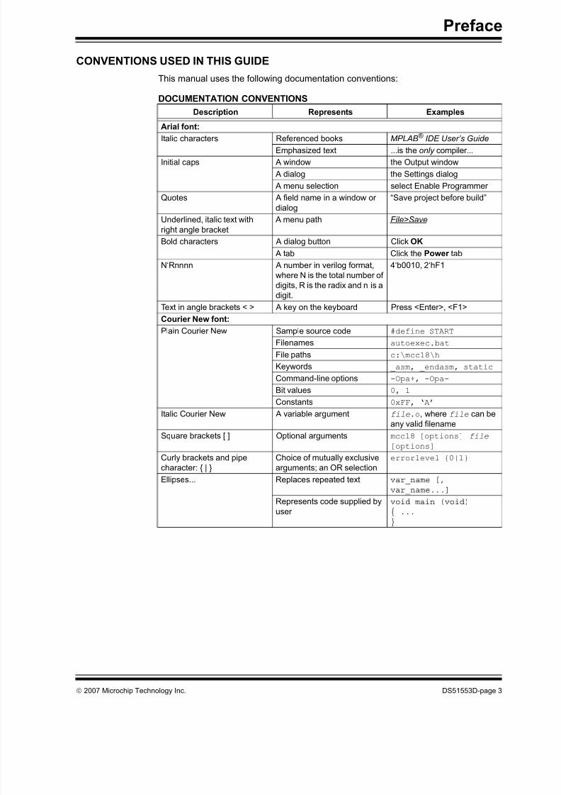
3.5 VSS
The power supply ground reference, VSS, must be at the same potential as the
application circuit.
3.6 OTHER CONSIDERATIONS
Minimize the distance the ICSP signals must travel by placing the ICSP connector as
close to the application circuit PIC® MCU as possible. Minimize any cable lengthbetween the PICkit™ 2 Microcontroller Programmer and application circuit PIC® MCU.
The goal is to keep the ICSP signals within the level and slew rate specifications for
successful programming.

8/8/2019 Pickit2 User Guide
http://slidepdf.com/reader/full/pickit2-user-guide 33/58
PICkit™ 2 MCU PROGRAMMER USER’S GUIDE
© 2007 Microchip Technology Inc. DS51553D-page 29
Chapter 4. PICkit ™ 2 Debug Express
4.1 INTRODUCTION
The PICkit™ 2 Microcontroller Programmer allows in-circuit debugging on selected
PIC® Microcontroller Units (MCUs). In-circuit debugging allows the designer to run,
examine and modify the program while the PIC® MCU is embedded in the hardware.
This greatly assists the designer in debugging the firmware and hardware together.
The Debug Express software interacts with the MPLAB® IDE software to run, stop and
single-step through programs. One breakpoint can be set and the processor can be
reset. Once the processor is stopped, the register’s contents can be examined and
modified.
4.1.1 Supported Devices
For a list of current devices supported by PICkit™ 2 Debug Express, see the “Readme
for PICkit 2.htm” file in the Readmes subdirectory of the MPLAB® IDE installation
directory.
4.1.2 Resources Used by PICkit™ 2 Debug Express
Due to the built-in in-circuit debugging capability of ICD devices and the ICSP function
offered by the debugger, the PICkit™ 2 Debug Express uses some on-chip resources
when debugging.
General Resources for Mid-Range Devices
• MCLR pin reserved for debugging; this pin cannot be used as digital I/O while
debugging.
• MCLR/VPP shared for programming.
• The ICSPDAT and ICSPCLK port pins are reserved for programming and in-circuit
debugging. Therefore, other functions multiplexed on these pins will not be
available during debug.
• One stack level not available.
Program and Data Memory Resources
The PICkit™ 2 Debug Express uses program memory and fi le register locations in the
target device during debugging. These locations are not available for use by user code.
In the MPLAB IDE, registers marked with an “R” in register displays represent reserved
registers.
Note: Debug Express requires MPLAB® IDE 7.50 version, or later.
Note: Debug Express requires 4.7k Ohm pull down resistors on ICSPCLK and
ICSPDAT. Newer PICkit™ 2 Microcontroller Programmers that have a Red
button have the pull downs internally. Older PICkit™ 2 Microcontroller
Programmers that have a Black button require that the pull downs be added
on the target board.

8/8/2019 Pickit2 User Guide
http://slidepdf.com/reader/full/pickit2-user-guide 34/58
PICkit™ 2 MCU Programmer User’s Guide
DS51553D-page 30 © 2007 Microchip Technology Inc.
For device specific reserved locations, see MPLAB® IDE help for the MPLAB® ICD 2.
In the MPLAB® IDE, select menu Help > Topics… . In the Help Topics dialog under
“Debuggers”, select “MPLAB® ICD 2” and click OK. In the MPLAB® ICD 2 Help dialog,
select “Operation” under the “Contents” tab. Select “MPLAB® ICD 2 Overview” then
“Resources Used By MPLAB® ICD 2”. A list of device families will be presented. Select
the device family of interest for more information on reserved device resources.
The following documentation may also be referenced:
• MPLAB® ICD 2 In-Circuit Debugger User’s Guide (DS51331)
4.2 PICkit™ 2 DEBUG EXPRESS
This section explains how to debug programs using the PICkit™ 2 Debug Express. It
is intended for those new to debugging programs, but familiar with the MPLAB® IDE
software.
For more information on how to use the MPLAB® IDE software, reference the following
documentation:
• MPLAB® IDE User’s Guide (DS51519)
• MPLAB® IDE Quick Start Guide (DS51281)
• MPLAB
®
IDE On-line Help
4.2.1 Selecting the Device and Development Mode
From the MPLAB® IDE menu bar, select the PIC® MCU device for this tutorial:
1. Select Configure > Select Device.
FIGURE 4-1: MPLAB ® IDE MENU BAR
2. Click on the Device drop-down list and select the PIC16F887 device. No other
changes need to be made in this dialog box.
3. Click OK.

8/8/2019 Pickit2 User Guide
http://slidepdf.com/reader/full/pickit2-user-guide 35/58
PICkit™ 2 Debug Express
© 2007 Microchip Technology Inc. DS51553D-page 31
FIGURE 4-2: SELECT DEVICE
4.2.2 PICkit™ 2 Microcontroller Programmer Debug Tool
Select the PICkit™ 2 Microcontroller Programmer as the debug tool:
• Select Debugger > Select Tool > PICkit 2 .
The Output window displays communication status between the PICkit™ 2
Microcontroller Programmer and Target Board, as shown in Figure 4-4.
FIGURE 4-3: PICkit™ 2 DEBUG TOOL

8/8/2019 Pickit2 User Guide
http://slidepdf.com/reader/full/pickit2-user-guide 36/58
PICkit™ 2 MCU Programmer User’s Guide
DS51553D-page 32 © 2007 Microchip Technology Inc.
FIGURE 4-4: OUTPUT WINDOW
4. Select Debugger > Settings to setup the PICkit™ 2 operation.
5. Click the “Connect on Startup” check box to enable the auto-connection feature.
6. Click Ok.
FIGURE 4-5: PICkit™ 2 SETTINGS

8/8/2019 Pickit2 User Guide
http://slidepdf.com/reader/full/pickit2-user-guide 37/58
PICkit™ 2 Debug Express
© 2007 Microchip Technology Inc. DS51553D-page 33
7. Select Debugger > Connect to connect to the PICkit™ 2.
The Output window displays communication status between the PICkit™ 2 and
Target Board.
FIGURE 4-6: PICkit™ 2 MICROCONTROLLER PROGRAMMER CONNECT
4.2.3 Updating PICkit™ 2 Firmware (Operating System)
Depending on the version of the MPLAB® IDE software or the selected device, amessage may appear indicating that the firmware needs to be updated. MPLAB ® IDE
will automatically install new firmware (see Figure 4-7).
FIGURE 4-7: UPDATING PICkit™ 2 FIRMWARE DIALOG
4.2.4 Running the Project Wizard
For this project, the MPASM™ Assembler tool will be used:
1. Select Project > Project Wizard to setup the first project. The Project Wizard
Welcome menu will display.
2. Click Next to continue to Step One.

8/8/2019 Pickit2 User Guide
http://slidepdf.com/reader/full/pickit2-user-guide 38/58
PICkit™ 2 MCU Programmer User’s Guide
DS51553D-page 34 © 2007 Microchip Technology Inc.
FIGURE 4-8: PROJECT WIZARD
3. Select the PIC16F887 device from the Device drop-down box.
4. Click Next to continue to Step Two.
FIGURE 4-9: STEP ONE
5. Select “Microchip MPASM Toolsuite” from the Active Toolsuite drop-down menu.
6. Click Next to continue to Step Three.
Make sure the tools are set to the proper executables by default in the C:\Program
Files\Microchip\MPASM Suite folder as follows:
• MPASM assembler should be pointing to mpasmwin.exe
• MPLINK Linker should be pointing to mplink.exe
• MPLIB Librarian should be pointing to mplib.exe.

8/8/2019 Pickit2 User Guide
http://slidepdf.com/reader/full/pickit2-user-guide 39/58
PICkit™ 2 Debug Express
© 2007 Microchip Technology Inc. DS51553D-page 35
FIGURE 4-10: STEP TWO
• In Step Three, type in the name and location of the project or click the Browse
button to locate the project files.
• Click Next to continue to Step Four.
FIGURE 4-11: STEP THREE
In Step Four, add the project files:
From the left pane window, go to
C:\Program Files\Microchip\PICkit 2 v2\DBE Demo. Select and highlight
the 16F887Demo.asm file and click the Add button. The file will be placed into the right
pane window.7. Click the check box next to the file to copy the file into the project directory.
8. Click Next to continue to the Summary window.
Note: Files can be added later if needed.

8/8/2019 Pickit2 User Guide
http://slidepdf.com/reader/full/pickit2-user-guide 40/58
PICkit™ 2 MCU Programmer User’s Guide
DS51553D-page 36 © 2007 Microchip Technology Inc.
FIGURE 4-12: ADD FILES
If any errors have been made, click on the Back button to return to any of the previous
steps in the Project Wizard. Click Finish.
FIGURE 4-13: PROJECT SUMMARY
4.2.5 PIC16F887 Debug Demo Project
After completing the project setup and exiting the Project Wizard, the Project Window
will display in the MPLAB® IDE desktop window, as shown in Figure 4-14.

8/8/2019 Pickit2 User Guide
http://slidepdf.com/reader/full/pickit2-user-guide 41/58
PICkit™ 2 Debug Express
© 2007 Microchip Technology Inc. DS51553D-page 37
FIGURE 4-14: PROJECT WINDOW
If needed, additional files can be added to the project using the Project Window. Right
click on any of the files or folders in the Project Window tree to display a pop-up window
with additional options for adding or removing files.
FIGURE 4-15: ADDING AND REMOVING FILES
4.2.6 Creating a Hex File
Select Project > Build All , or right click on the project name in the Project Window and
select “Build All” from the pop-up menu. The MPASM assembler will create a hex file
with the same name as the source .asm file.
FIGURE 4-16: BUILD PROJECT

8/8/2019 Pickit2 User Guide
http://slidepdf.com/reader/full/pickit2-user-guide 42/58
PICkit™ 2 MCU Programmer User’s Guide
DS51553D-page 38 © 2007 Microchip Technology Inc.
FIGURE 4-17: OUTPUT WINDOW
4.2.7 Setting Debug Options
Before debugging can begin, the device Configuration bits need to be selected.
4.2.7.1 CONFIGURATION BITS
The Configuration bits that are to be programmed into the device are set from within
the program. These bits can be verified using the Configuration Bits dialog window.
• Select Configure > Configuration Bits.
• To change the setting for a category, double click on the text in the “Setting”
column and select the appropriate setting for the corresponding category.
The following Configuration bits should be set for this tutorial:
Config1:
• Oscillator – Internal RC No Clock
• Watchdog Timer – Off
• Power-Up Timer – On
• Master Clear Enable – MCLR is external• Code-Protect – Off
• Data EE Protect – Off
• Brown-Out Detect – BOD and SBOREN Disabled
• Internal-External Switch Over Mode – Disabled
• Monitor Clock Fail-safe – Disabled
• Low-Voltage Program – Disabled
Config 2:
• Self Write Enable – No Protection
• Master Brown-out Reset Sel Bit – Brown-out at 2.1V

8/8/2019 Pickit2 User Guide
http://slidepdf.com/reader/full/pickit2-user-guide 43/58
PICkit™ 2 Debug Express
© 2007 Microchip Technology Inc. DS51553D-page 39
FIGURE 4-18: CONFIGURATION BIT SETTINGS
4.2.8 Loading Program Code for Debugging
• Select Debugger > Select Tool > PICkit 2 to select the PICkit™ 2 Microcontroller
Programmer as the debug tool.
• Select Debugger > Program to program the 16F887Demo.asm file into the
PIC16F887 on the 44-Pin Demo Board.
FIGURE 4-19:
Programming will only take a few seconds. During programming, the PICkit™ 2 tab of
the Output dialog window will display the current phase of operation. When program-
ming is complete, the dialog should look similar to Figure 4-20.
Note: The debug executive code is automatically programmed in the upper
program memory of the PIC16F887 (target device) for the PICkit™ 2 debug
functions. Debug code must be programmed into the target PIC®
MCU touse the in-circuit debugging capabilities of the PICkit™ 2 Programmer.

8/8/2019 Pickit2 User Guide
http://slidepdf.com/reader/full/pickit2-user-guide 44/58
PICkit™ 2 MCU Programmer User’s Guide
DS51553D-page 40 © 2007 Microchip Technology Inc.
FIGURE 4-20: OUTPUT WINDOW – PICkit™ 2 TAB
4.2.9 PIC16F887 Debug Demo
The PICkit™ 2 Microcontroller Programmer executes in either Real-Time or Step
mode. Real-Time execution occurs when the PIC16F887, on the 44-Pin Demo Board,is in MPLAB® IDE’s Run mode. Step mode execution can be accessed after the
processor is halted.
The following toolbar buttons can be used for quick access to commonly used debug
operations:
4.2.9.1 REAL-TIME MODE
Open the 16F887Demo.asm file:
1. Double click on the 16F887Demo.asm file from the Project Window or select
File > Open from the toolbar menu.
2. Select Debugger > Run, or click the Run button.
3. Turn the potentiometer (RA0), located on the demo board and observe the LEDs.
If the program was working properly, the LEDs would rotate faster or slower depending
on which direction the potentiometer is turned. However, a bug has been intentionallyplaced in the code for debugging demonstration purposes. See the next section
Section 4.2.10 “Debugging the PIC16F887 Debug Demo Code” for debugging
instructions.
4. Select Debugger > Halt , or click the Halt button to stop the program execution.
5. Select Debugger > Reset to reset the program.
Debugger Menu Toolbar Buttons
Run
Halt
Animate
Step Into
Step Over Step Out
Reset

8/8/2019 Pickit2 User Guide
http://slidepdf.com/reader/full/pickit2-user-guide 45/58
PICkit™ 2 Debug Express
© 2007 Microchip Technology Inc. DS51553D-page 41
4.2.10 Debugging the PIC16F887 Debug Demo Code
Any of the following issues can prevent the PIC16F887 Debug Demo program from
working properly:
• The A/D converter value is not being written properly to the Delay routine.
• The A/D converter is not enabled or has not been set to convert.
• A typing error in the source code has caused the program to function improperly.
To explore the first listed possible issue, set a breakpoint at the line of code that writes
the value of the A/D result to the high-order Delay byte:
1. Place the cursor on the following line of code in the 16F887Demo.asm file:
movwf Delay+1, as shown in Figure 4-21.
At this breakpoint, the program will stop once the A/D conversion has completed.
2. Right click to display a drop-down menu.
3. Select Set Breakpoint from the drop-down menu.
The program marks the line with the letter B in a red octagon outline, as shown
in Figure 4-21.
FIGURE 4-21: BREAKPOINT
4. Select Debugger > Run, or click the Run button to run the program in Real-Time
mode.
A breakpoint stops a program’s execution when the program executes the line
marked as a breakpoint.
5. Mouse over “ADRESH” in the listing file and it will show the value of the file
register (see Figure 4-22).

8/8/2019 Pickit2 User Guide
http://slidepdf.com/reader/full/pickit2-user-guide 46/58
PICkit™ 2 MCU Programmer User’s Guide
DS51553D-page 42 © 2007 Microchip Technology Inc.
FIGURE 4-22: ADRESH REGISTER VALUE
6. Adjust the POT and continue the program continue by selecting Debug > Run.
The program will run through the loop and halt.
7. Mouse over “ADRESH” again, the A/D result has not changed. Thus it seems the
A/D conversion is not working. The A/D conversion initialization and setup occurs
at the beginning of the program.
FIGURE 4-23: PROGRAM HALTED
8. Select Debugger > Reset to reset the program. The first instruction should be
indicated by a green arrow.
9. Select View > Watch to open a new Watch window. This window allows the user
to watch the A/D register value change as the program executes. The Watch
dialog opens with theWatch_1
tab selected, as shown in Figure 4-24.

8/8/2019 Pickit2 User Guide
http://slidepdf.com/reader/full/pickit2-user-guide 47/58
PICkit™ 2 Debug Express
© 2007 Microchip Technology Inc. DS51553D-page 43
FIGURE 4-24: WATCH WINDOW
10. Select ADCON0 and click on the Add SFR button to add ADCON0 to the Watch
window.
11. Repeat Step 10 to add ADCON1 and ADRESH to the Watch window. The
selected SFRs should be visible in the Watch window as shown in Figure 4-25.
FIGURE 4-25: ADD SFR
12. Select Debugger > Run to the run the program in Real-Time mode. This time the
program will stop after it executes the breakpoint line of code and the instruction
after the breakpoint will be indicated as shown in Figure 4-26.
FIGURE 4-26: PROGRAM HALTED AFTER BREAK

8/8/2019 Pickit2 User Guide
http://slidepdf.com/reader/full/pickit2-user-guide 48/58
PICkit™ 2 MCU Programmer User’s Guide
DS51553D-page 44 © 2007 Microchip Technology Inc.
13. Examine the values of the ADCON0 and ADCON1 registers in the Watch
window. The ADCON0 value is ‘0x40’ (b’01000000’). This corresponds to the
hex value designated in the program. However, this is not correct. A review of the
“PIC16F882/883/884/886/887 Data Sheet ” (DS41291), Analog-to-Digital (A/D)
Converter Module section, indicates that the last bit should be a ‘1’
(b’01000001’) to turn on the A/D module. To fix this bug, change:
“movlw 0x40”
to“movlw 0x41”, as shown in Figure 4-27.
FIGURE 4-27: A/D MODULE CODE
14. Select File > Save to save the changes.
15. Select Project > Build All to rebuild the project. A message will indicate that the
program has been rebuilt. The PICkit™ 2 Programmer must be reprogrammed
for the changes to take effect.
16. Select Debugger > Program to reprogram the PICkit™ 2 Programmer with the
changes. When the PICkit™ 2 Programmer dialog indicates “Programming
Succeeded”, the program is ready to run again.
17. Right-click on the line of code that previously had the breakpoint and select
Remove > Breakpoint .
18. Select Debugger > Run to run the program in Real-Time mode. Turn the
potentiometer (RA0) to change the value displayed on the LEDs.
The source code in this tutorial contained only one bug. However, real code may have
more. Using the PICkit™ 2 Programmer and MPLAB® IDE debugging functions, users
can successfully find and fix problems in their code.
4.2.11 Programming the Application
When the program is successfully debugged and running, the next step is to program
the PIC® MCU for stand-alone operation in the finished design. When doing this, the
resources reserved by the ICD are released for use by the application. To program the
application, use the following steps:

8/8/2019 Pickit2 User Guide
http://slidepdf.com/reader/full/pickit2-user-guide 49/58
PICkit™ 2 Debug Express
© 2007 Microchip Technology Inc. DS51553D-page 45
1. Disable PICkit™ 2 Programmer as a debug tool by selecting Debugger > Select
Tool > None.
2. Select PICkit™ 2 Programmer as the programmer in Programmer > Select Tool
menu.
3. Optional: Set up the ID in Configure > ID Memory .
FIGURE 4-28: CONFIGURE – ID MEMORY
FIGURE 4-29: USER ID MEMORY
4. Set up the parameters for programming on the Programmer > Settings Program
tab.
5. Select Programmer > Program.
Now the PICkit™ 2 Programmer can reset and run the target.

8/8/2019 Pickit2 User Guide
http://slidepdf.com/reader/full/pickit2-user-guide 50/58
PICkit™ 2 MCU Programmer User’s Guide
DS51553D-page 46 © 2007 Microchip Technology Inc.
NOTES:

8/8/2019 Pickit2 User Guide
http://slidepdf.com/reader/full/pickit2-user-guide 51/58
PICkitTM 2 MCU PROGRAMMER USER’S GUIDE
© 2007 Microchip Technology Inc. DS51553D-page 47
Chapter 5. Troubleshooting
5.1 INTRODUCTION
This chapter describes questions and answers to common problems associated with
using the PICkit™ 2 Microcontroller Programmer and how to resolve them.
5.2 FREQUENTLY ASKED QUESTIONS
Device is not recognized
Question
Why am I receiving a “No Device Found ” message?
Answer
Verify that the device is supported and that the target MCU is connected to the PICkit™ 2
Microcontroller Programmer in accordance with Chapter 3. “PICkit™ 2 Programmer
and ICSP™”. Verify that PIC18F_J_, PIC24, and dsPIC33 devices have an appropriate
capacitance on the VDDCORE/VCAP pin in accordance with the device data sheet.
Current Limit Exceeded
Question
Why am I receiving the error message “USB Hub Current Limit Exceeded ” from the
Microsoft® Windows® program?
Answer
Check the application circuit is not drawing more than about 25 mA from the PICkit™
2 Programmer.
Microsoft® Windows® Driver
Question
After plugging the PICkit™ 2 Microcontroller Programmer into the USB port, Windows®
98 SE asks for a driver. Where is the driver?
Answer
PICkit™ 2 Microcontroller Programmer uses the drivers included with Windows®.
When Windows® 98 SE prompts for a driver, select “Search for the best driver for your
device.” Then select the check box next to “Microsoft Windows Update” and click Next.
Windows will automatically install the appropriate driver. Do not use Microchip’s ICD 2
USB driver.
Verify and Read Return all Zeros
Question
When the Verify or Read buttons are clicked, the Program Memory window comes up
with all zeros. What is wrong?
Answer
The device may be code-protected. Ensure code protection has not been selected in
the Configuration Word.

8/8/2019 Pickit2 User Guide
http://slidepdf.com/reader/full/pickit2-user-guide 52/58
PICkitTM 2 MCU Programmer User’s Guide
DS51553D-page 48 © 2007 Microchip Technology Inc.
Microsoft ® Windows ® 95/98/NT
Question
Can I run on Windows® 95/98/NT?
Answer
No. These operating systems either do not support USB or have drivers that are not
compatible.
VDD /VPP Errors
Question
Why do I keep getting a “VDD Error” or “VPP Error”?
Answer
This error indicates that the PICkit™ 2 Programmer is not able to drive VDD or VPP to
the intended voltage. Check the circuit board for shorts, for large current draw, and
verify that the target MCU is connected to the PICkit™ 2 Programmer in accordance
with Chapter 3. “PICkit™ 2 Programmer and ICSP™”. Make sure that VDD capaci-
tance is not reducing the VDD rise time longer than 500 μs.
Programming ErrorsQuestion
Why am I able to program some parts but not others?
Answer
If some parts are configured for Low-Voltage Programming, a floating PGM pin can
interfere with programming. Use a resistor to pull this pin low when programming.
Some Mid-Range parts, such as the PIC16F72, 73, 74, 76, 77 family and PIC16F737,
747, 767, 777 family require a minimum programming VDD of +4.75V. Depending on
the USB voltage, the PICkit™ 2 Microcontroller Programmer may not be able to supply
+4.75V on VDD. Program these parts using an external +5.0V power supply.
Some PIC18F parts require significant bypass capacitance on VDD. Try increasing the
total bypass capacitance up to 10 uF.
PIC18F_J_ parts, PIC24, and dsPIC® DSC parts require a 4.7 uF capacitor on the
VDDCORE/VCAP pin in order to function properly. If not using a separate regulator to
supply VDDCORE, ensure that the ENVREG pin is tied to VDD.
Debug Express Connection Problems
Question
While using PICkit™ 2 Programmer as a debugger, I frequently get the error “Unable
to Enter Debug Mode” when programming the device. What’s wrong?
Answer
During debugging the ICSPCLK and ICSPDAT signal lines must be completely
isolated from other circuitry in the application. PICkit™ 2 Microcontroller Program-mers with a black push button require that 4.7k Ohm pull-down resistors be added
from both ICSPCLK and ICSPDAT to GND. Newer PICkit™ 2 Microcontroller
Programmers with a red push button have the pull downs internally.

8/8/2019 Pickit2 User Guide
http://slidepdf.com/reader/full/pickit2-user-guide 53/58
PICkitTM 2 MCU PROGRAMMER USER’S GUIDE
© 2007 Microchip Technology Inc. DS51553D-page 49
Chapter 6. Updating the PICkit™ 2 Programmer Operating System
6.1 INTRODUCTION
This chapter describes how to update the PICkit™ 2 Microcontroller Programmer’s
operating system.
6.2 UPDATING THE PICkit™ 2 MICROCONTROLLER PROGRAMMER
To update the PICkit™ 2 Microcontroller Programmer Operating System, complete the
following steps.
Step 1. Download the latest PICkit™ 2 Microcontroller Programmer Operating
System from the Microchip web site at www.microchip.com.
Step 2. From the menu, select Tools > Download PICKit 2 Operating System as
shown in Figure 6-1.
FIGURE 6-1: DOWNLOAD PICkit™ 2 PROGRAMMER OPERATING
SYSTEM
Step 3. Browse to the directory where the latest Operating System code was
saved as shown in Figure 6-2.

8/8/2019 Pickit2 User Guide
http://slidepdf.com/reader/full/pickit2-user-guide 54/58
PICkitTM 2 MCU Programmer User’s Guide
DS51553D-page 50 © 2007 Microchip Technology Inc.
FIGURE 6-2: OPEN PICkit™ 2 PROGRAMMER OPERATING SYSTEM
Step 4. Select the PK2*.hex file and click on the Open button.
The progress of the OS update will be displayed in the status bar of the programming
software and the Busy LED on the PICkit™ 2 Microcontroller Programmer will flash.
When the update completes successfully, the status bar will display “Operating System
Verified” and the Busy LED will go out. The operating system update is then complete.

8/8/2019 Pickit2 User Guide
http://slidepdf.com/reader/full/pickit2-user-guide 55/58
PICkitTM 2 MCU PROGRAMMER USER’S GUIDE
© 2007 Microchip Technology Inc. DS51553D-page 51
Appendix A. Hardware Schematics
A.1 INTRODUCTION
This appendix contains PICkit™ 2 Microcontroller Programmer schematic diagrams.
FIGURE A-1: PICkit™ 2 MICROCONTROLLER PROGRAMMER
SCHEMATIC DIAGRAM (PAGE 1 OF 2)
5 4 3 2 1
1 2 3 4 5 6
G
D S
1 2 3 4
5 6 7 8
1 2 3 4
5 6 7 8
3 1
4
5 2
1
2 3 4 5 6 7
2 0 8 9
1 0
1 1
1 2
1 3
1 4
1 5
1 6
1 7
1 8
1 9
2 1
2 2
2 3
2 4
2 5
2 6
2 7
2 8
A 0
A 2
V s s
V c c
W P
S C L
A 1
S D A
A 0
A 2
V s s
V c c
W P
S C L
A 1
S D A
- +
R B 7 / K B I 3 / P G D
R B 6 / K B I 2 / P G C
R B 5 / K B I 1 / P G M
R B 4 / A N 1 1 / K B I 0
R B 3 / A N 9 / C C P 2 / V P O
R B 2 / A N 8 / I N T 2 / V M O
R B 1 / A N 1 0 / I N T 1 / S C K / S C L
R B 0 / A N 1 2 / I N T 0 / F L T 0 / S D I / S D A
V S S
R C 7 / R X / D T / S D O
R C 6 / T X / C K
R C 5 / D + / V P
R C 4 / D - / V M
M C L R / V P P / R E 3
R A 0 / A N 0
R A 1 / A N 1
R A 2 / A N 2 / V R E F - / C V R E F
R A 3 / A N 3 / V R E F +
R A 4 / T 0 C K I / C 1 O U T / R C V
R A 5 / A N 4 / S S / H L V D I N / C 2 O U T
V D D
V S S
O S C 1 / C L K I
O S C 2 / C L K O /
R A 6
R C 0 / T 1 O S O / T 1 3 C K I
R C 1 / T 1 O S I / C C P 2 / U O E
R C 2 / C C P 1
V U S B
+ 5 V
_ U S
B
+ 5 V
_ U S B
+ 5 V
_ U S B
+ 5 V
_ U S B
+ 5 V
_ U S B
+ 5 V
_ U S B
+ 5 V
_ U S B
+ V
_ T G T
+ 5 V
_ U S B
+ 5 V
_ U S B
+ 5 V
_ U S B
+ 5 V
_ U S B
A U X
W P M
C L R
_ T G T
S C L
S D A
V d d
_ T G T
_ P
V d d
_ T G T
_ N
V D D
_ T G T
_ F B
V P P
_ O N
I C S P D A T
I C S P C L K
V P P
_ P U M P
V P P
_ F E E D B A C K
S D A
S C L
W P
W P S
D A
S C L
C 1
0 . 1
F
C 4
0 . 1
F
C 6
0 . 1
F
C 7 0 . 4
7
F
C 8
0 . 1
F
C 9
0 . 1
F
C 1 0
0 . 1
F
C 1 6
0 . 1
F
C 2
2 2 p F
C 3
2 2 p F
C 5
1 0
F 1 6 V
D S 1
D S 2
D S 3
J 2
J 1
Q 1
I R L M L 6 4 0 2
R 1
4 7 0 Ω
R 2
4 7 0 Ω
R 3
4 7 0 Ω
R 8
2 . 7
K Ω
R 9
2 . 7
K Ω
R
3 2
1
0 K Ω
R
3 3
3
3 Ω
R 3 4
2 . 7
K Ω
R 4
1 0 K Ω
R 5
1 0 K Ω
R 6
1 0 K Ω
R 7
1 0 K Ω
R 3 1
1 0 0 Ω
S W 1
P R O G R A M
U 3
2 4 L C 5 1 2
U 4
2 4 L C 5 1 2
U 2
M C P 6 0 0 1 U
U 1
P
I C 1 8 F 2 5 5 0 / S O
X 1
2 0 M H z
U S B
P O W E R
T A R G E T
G R E E N
Y E L L O W
I C S P
N C
B U S Y
R E D
2 ^ 1
2 ^ 0
V D D_ T G T
_ A D J
N C
M i n i - B
N O T E : R
3 2 a n d C 1 6 n o t p o p u l a t e d
T M

8/8/2019 Pickit2 User Guide
http://slidepdf.com/reader/full/pickit2-user-guide 56/58
PICkitTM 2 MCU Programmer User’s Guide
DS51553D-page 52 © 2007 Microchip Technology Inc.
FIGURE A-2: PICkit™ 2 MICROCONTROLLER PROGRAMMER
SCHEMATIC DIAGRAM (PAGE 2 OF 2)
6 5 4 3 2 1
1 2 3
4 5 6
G
D
S G
D S
+ V
_ T G T
+ V
_ T G T
+ 5 V
_ U S B
A U X
M C L R
_ T G T
V D D
_ T G T
_ P
V D D
_ T G T
_ N
I C S P D A T
I C S P C L K
V P P
_ O N
V P P
_ P U M P
V P P
_ F E E D B A C K
C 1 2
0 . 1
F
C 1 3
0 . 1
F
C 1 1
1 0
F
1 6 V
C 1 4
1 0
F 1 6 V
C 1 5
4 7
F
2 5 V
M M B D 4 1 4 8
D 1
B A T 5 4
D 3
Z H C S 1 0 0 0
D 4
J 3
L 1
6 8 0 u
H
Q 4
M M B T 3 9 0 4
Q 7
M M B T 3 9 0 4
Q 8
M M B T 3 9 0 4
Q 2
M M B T 3 9 0 6
Q 3
M M B T 3 9 0 6
Q 5
M M B T 3 9 0 6
Q 6
M M B T 3 9 0 6
R 1 2
1 0 K Ω
R 1 6
1 0 K Ω
R 1 7
8 2 0 Ω
R 2 2
4 . 7
K Ω
R 2 3
1 0 0 K Ω
R 2 4
2 . 7
K Ω
R 2 5
1 0 K Ω
R 2 6
4 . 7
K Ω
R 2 8
1 0 0 Ω
R 3 5
4 . 7
K Ω
R 3 6
4 . 7
K Ω
R 1 0
1 0 Ω
R 1 1
3 3 Ω
R 1 3
1 K Ω
R 1 4
1 0 Ω
R 1 5
3 3 Ω
R 1 9
1 0 Ω
R 2 0
3 3 Ω
R 2 1
1 K Ω
R
2 7
1 0
K Ω
R
2 9
1 0
K Ω
R
3 0
2 . 7
K Ω
Q 2 ( P )
Q 1 ( N )
U 5
F D C 6 4 2 0 C
I C S P
V P P
V D D _ T G T
L o w
t u r n s o n
P
H i g h t u r n s o n
N
A U X
I C S P C L K
I C S P D A T
G N D
V D D
_ T G T
V P P
V D D
_ T G T
_ F B
T M

8/8/2019 Pickit2 User Guide
http://slidepdf.com/reader/full/pickit2-user-guide 57/58
© 2007 Microchip Technology Inc. DS51553D-page 53
Hardware Schematics
NOTES:

8/8/2019 Pickit2 User Guide
http://slidepdf.com/reader/full/pickit2-user-guide 58/58
AMERICASCorporate Office2355 West Chandler Blvd.
Chandler, AZ 85224-6199
Tel: 480-792-7200
Fax: 480-792-7277
Technical Support:
http://support.microchip.com
Web Address:
www.microchip.com
AtlantaDuluth, GA
Tel: 678-957-9614
Fax: 678-957-1455
BostonWestborough, MA
Tel: 774-760-0087
Fax: 774-760-0088
ChicagoItasca, IL
Tel: 630-285-0071
Fax: 630-285-0075
DallasAddison, TX
Tel: 972-818-7423
Fax: 972-818-2924
DetroitFarmington Hills, MI
Tel: 248-538-2250
Fax: 248-538-2260
KokomoKokomo, IN
Tel: 765-864-8360
Fax: 765-864-8387
Los Angeles
Mission Viejo, CA
Tel: 949-462-9523
Fax: 949-462-9608
Santa Clara
Santa Clara, CA
Tel: 408-961-6444
Fax: 408-961-6445
Toronto
Mississauga, Ontario,Canada
Tel: 905-673-0699
Fax: 905-673-6509
ASIA/PACIFIC
Asia Pacific Office
Suites 3707-14, 37th Floor
Tower 6, The Gateway
Harbour City, Kowloon
Hong Kong
Tel: 852-2401-1200
Fax: 852-2401-3431
Australia - SydneyTel: 61-2-9868-6733
Fax: 61-2-9868-6755
China - BeijingTel: 86-10-8528-2100
Fax: 86-10-8528-2104
China - Chengdu
Tel: 86-28-8665-5511
Fax: 86-28-8665-7889
China - Fuzhou
Tel: 86-591-8750-3506
Fax: 86-591-8750-3521
China - Hong Kong SAR
Tel: 852-2401-1200
Fax: 852-2401-3431
China - Qingdao
Tel: 86-532-8502-7355
Fax: 86-532-8502-7205
China - ShanghaiTel: 86-21-5407-5533
Fax: 86-21-5407-5066
China - Shenyang
Tel: 86-24-2334-2829
Fax: 86-24-2334-2393
China - Shenzhen
Tel: 86-755-8203-2660
Fax: 86-755-8203-1760
China - Shunde
Tel: 86-757-2839-5507
Fax: 86-757-2839-5571
China - Wuhan
Tel: 86-27-5980-5300
Fax: 86-27-5980-5118
China - XianTel: 86-29-8833-7252
Fax: 86-29-8833-7256
ASIA/PACIFIC
India - BangaloreTel: 91-80-4182-8400
Fax: 91-80-4182-8422
India - New Delhi
Tel: 91-11-4160-8631
Fax: 91-11-4160-8632
India - Pune
Tel: 91-20-2566-1512
Fax: 91-20-2566-1513
Japan - Yokohama
Tel: 81-45-471- 6166
Fax: 81-45-471-6122
Korea - DaeguTel: 82-53-744-4301
Fax: 82-53-744-4302
Korea - SeoulTel: 82-2-554-7200
Fax: 82-2-558-5932 or
82-2-558-5934
Malaysia - Penang
Tel: 60-4-646-8870
Fax: 60-4-646-5086
Philippines - Manila
Tel: 63-2-634-9065
Fax: 63-2-634-9069
Singapore
Tel: 65-6334-8870Fax: 65-6334-8850
Taiwan - Hsin Chu
Tel: 886-3-572-9526
Fax: 886-3-572-6459
Taiwan - KaohsiungTel: 886-7-536-4818
Fax: 886-7-536-4803
Taiwan - TaipeiTel: 886-2-2500-6610
Fax: 886-2-2508-0102
Thailand - Bangkok
Tel: 66-2-694-1351
Fax: 66-2-694-1350
EUROPE
Austria - Wels
Tel: 43-7242-2244-39
Fax: 43-7242-2244-393
Denmark - CopenhagenTel: 45-4450-2828
Fax: 45-4485-2829
France - ParisTel: 33-1-69-53-63-20
Fax: 33-1-69-30-90-79
Germany - MunichTel: 49-89-627-144-0
Fax: 49-89-627-144-44
Italy - MilanTel: 39-0331-742611
Fax: 39-0331-466781
Netherlands - Drunen
Tel: 31-416-690399
Fax: 31-416-690340
Spain - MadridTel: 34-91-708-08-90
Fax: 34-91-708-08-91
UK - WokinghamTel: 44-118-921-5869
Fax: 44-118-921-5820
WORLDWIDE SALES AND SERVICE


![User Guide...User. {{]}]} {}]}](https://img.pdfslide.net/doc/110x75/60918ca14327954d24291644/-user-guide-user-.jpg)