Embed Size (px)
Citation preview

The compact alternative to a benchtop oscilloscope
PicoScope® 2000 Series
www.picotech.com
2 or 4 analog channelsMSO models with 16 digital channels
Up to 100 MHz bandwidthUp to 1 GS/s sampling rate
Up to 128 MS buffer memoryBuilt-in arbitrary waveform generator
USB-connected and powered
From $115 / €95 / £79

PicoScope 2000 Series
2+16-channel mixed-signal oscilloscope (MSO)
4-channel oscilloscope
The PicoScope 6 software takes advantage of the display size and resolution and processing power of your PC – in this case displaying four analog signals, a zoomed view of two of the signals (undergoing serial decoding), and a spectrum view of a third, all at the same time. Unlike a conventional benchtop oscilloscope, the size of the display is limited only by the size of your computer monitor. The software is also easy to use on touch-screen devices – you can pinch to zoom and drag to scroll.
Advanced oscilloscope display2-channel oscilloscope: 2206B, 2207B and 2208B
2-channel oscilloscope: 2204A and 2205A
Introducing the PicoScope 2000 SeriesThe PicoScope 2000 Series offers you a choice of 2- and 4-channel oscilloscopes, plus mixed-signal oscilloscopes (MSOs) with 2 analog + 16 digital inputs. All models feature spectrum analyzers, function generators, arbitrary waveform generators and serial bus analyzers, and the MSO models also function as logic analyzers.
The PicoScope 2000A models all deliver unbeatable value for money, with excellent waveform visualization and measurement to 25 MHz for a range of analog and digital electronic and embedded system applications. They are ideal for education, hobby and field service use.
The PicoScope 2000B models have the added benefits of deep memory (up to 128 MS), higher bandwidth (up to 100 MHz) and faster waveform update rates, giving you the performance you need to carry out advanced analysis of your waveform, including serial decoding and plotting frequency against time.

PicoScope 2000 Series
High signal integrityHere at Pico Technology, we’re proud of the dynamic performance of our products. Careful front-end design and shielding reduce noise, crosstalk and harmonic distortion. Decades of oscilloscope design experience can be seen in improved pulse response and bandwidth flatness.
The result is simple: when you probe a circuit, you can trust in the waveform you see on the screen.
Powerful, portable and super-smallThe PicoScope 2000 Series oscilloscopes are compact enough to fit easily into your laptop bag along with all their probes and leads. These modern alternatives to bulky benchtop devices are ideal for a wide range of applications including design, test, education, service, monitoring, fault-finding and repair and are perfect for engineers on the move.
Fast samplingThe PicoScope 2000 Series oscilloscopes provide fast real-time sampling rates of up to 1 GS/s on the analog channels: this represents a timing resolution of 1 ns.
For repetitive analog signals, equivalent-time sampling (ETS) mode can boost the maximum effective sampling rate up to 10 GS/s, allowing even finer resolution down to 100 ps. All scopes support pre-trigger and post-trigger capture using the full memory depth.
High-end features as standardBuying a PicoScope is not like making a purchase from other oscilloscope companies, where increased functionality can considerably raise the price. PicoScopes are all-inclusive instruments, with no need for expensive upgrades to unlock the hardware. Other advanced features such as resolution enhancement, mask limit testing, serial decoding, advanced triggering, automatic measurements, math channels (including the ability to plot frequency and duty cycle against time), XY mode and segmented memory are all included in the price.
USB connectivityThe USB connection makes printing, copying, saving, and emailing your data from the field quick and easy. The high-speed USB interface allows fast data transfer, while USB powering removes the need to carry around a bulky external power supply.
FlexibilityThe PicoScope software offers a breadth of advanced features via a user-friendly interface. As well as the standard Windows installation, PicoScope Beta software also works effectively on Linux and Mac operating systems, giving you the freedom to choose which platform you operate your PicoScope from.
Unique commitment to product supportYour PicoScope gets better the longer you use it, thanks to the regular free updates we supply for both the PC software and the oscilloscope firmware throughout the life of the product: the performance and functionality of the scope both keep improving, without you paying a penny more than the purchase price.
This level of support, combined with the personal service provided by our technical and sales support teams, is reflected in the consistently good feedback we get from users of our products, many of whom have gone on to be regular customers.

PicoScope 2000 Series
PicoScope 6 softwareThe PicoScope software display can be as simple or as detailed as you need. Begin with a single view of one channel, and then expand the display to include up to four live channels, plus math channels and reference waveforms.
Tools > Serial decoding: Decode multiple serial data signals and display the data alongside the physical signal or as a detailed table.Tools > Reference waveforms: Store waveforms in memory or on disk and display them alongside live inputs. Ideal for diagnostics and production testing.Tools > Masks: Automatically generate a test mask from a waveform or draw one by hand. PicoScope highlights any parts of the waveform that fall outside the mask and shows error statistics.
Movable axes: The vertical axes can be dragged up and down. This feature is particularly useful when one waveform is obscuring another. There’s also an Auto Arrange Axes command.
Spectrum view: View FFT data alongside scope view or in dedicated spectrum mode.
Automatic measurements: Display calculated measurements for troubleshooting and analysis. You can add as many measurements as you need on each view. Each measurement includes statistical parameters showing its variability.
Trigger toolbar Quick access to main controls, with advanced triggers in a pop-up window.
Ruler legend: Absolute and differential ruler measurements are listed here.
Channel options: Set axis offset and scaling, DC offset, zero offset, resolution enhancement, custom probes, and filtering here.
Function generator: Generates standard signals or arbitrary waveforms. Includes frequency sweep mode.
Auto setup button:Configures the timebase and voltage ranges for stable display of signals.
Oscilloscope controls: Controls such as voltage range, channel enable, timebase and memory depth are placed on the toolbar for quick access, leaving the main display area clear for waveforms.
Rulers: Each axis has two rulers that can be dragged across the screen to make quick measurements of amplitude, time and frequency.
Trigger marker: Drag the marker to adjust trigger level and pre-trigger time.
Views: PicoScope is carefully designed to make the best use of the display area. The waveform view is much bigger and higher resolution than a typical benchtop scope. You can add new scope and spectrum views with automatic or custom layouts.
Waveform replay tools: PicoScope automatically records up to 10 000 of the most recent waveforms. You can quickly scan through to look for intermittent events, or use the Buffer Navigator to search visually.
Zoom and pan tools: PicoScope makes it easy to zoom into large waveforms. Either use the zoom-in, zoom-out and pan tools, or click and drag in the Zoom Overview window for fast navigation.
Touch-screen support:Handy buttons let you make fine adjustments with a mouse or a touch screen.

PicoScope 2000 Series
PicoScope 6 software with mixed digital and analog signalsThe flexibility of the PicoScope 6 software interface allows high-resolution viewing of all analog and digital channels at once, along with math channels and reference waveforms. You can use the whole of your PC’s display to view the waveforms, ensuring you never miss a detail again.
Display format: Display selected bits individually or as groups in numerical or ASCII format.
Show by level: Group bits into fields and then display as an analog level.
Digital channels button: Set up and display digital inputs. View analog and digital signals on the same timebase.
Oscilloscope controls: PicoScope’s full analog-domain controls, including zoom, filtering, and function generator, are all available in MSO digital signal mode.
Split-screen display: PicoScope can display both analog and digital signals at the same time. The split-screen display can be adjusted to give more or less space to the analog waveforms.
Analog waveforms: View analog waveforms time-correlated with digital inputs.
Advanced triggers: Additional Digital and Logic trigger options are available for digital channels.
Rename: The digital channels and groups can be renamed. Groups can be expanded or collapsed in the digital view.
Rulers: Drawn across both analog and digital panes so signal timings can be compared.

PicoScope 2000 Series
Digital triggeringMost digital oscilloscopes still use an analog trigger architecture based on comparators. This can cause time and amplitude errors that cannot always be calibrated out. The use of comparators often limits the trigger sensitivity at high bandwidths and can also create a long trigger rearm delay.
For 25 years, Pico Technology has been pioneering the use of full digital triggering using the actual digitized data. This eliminates trigger errors and allows our oscilloscopes to trigger on the smallest signals, even at the full bandwidth. All triggering is digital, resulting in a threshold resolution equal to the digitizing resolution, with programmable hysteresis and optimal waveform stability.
The reduced rearm delay provided by digital triggering, together with segmented memory, allows the capture of events that happen in rapid sequence. Rapid triggering, available on most models, can capture a new waveform every 1 or 2 microseconds, depending on the model, at the fastest timebase, until the buffer is full. The mask limit testing function helps to detect waveforms that fail to meet your specifications.
As well as the standard range of triggers found on most oscilloscopes, the PicoScope 2000 Series offers one of the best selections of advanced triggers available. These include pulse width, window and dropout triggers to help you find and capture your signal quickly.
Arbitrary waveform and function generatorsAll PicoScope 2000 Series oscilloscopes have a built-in function generator and arbitrary waveform generator (AWG). The function generator can produce sine, square, triangle and DC level waveforms, and many more besides, while the AWG allows you to import waveforms from data files or create and modify them using the built-in graphical AWG editor.
As well as level, offset and frequency controls, advanced options allow you to sweep over a range of frequencies. Combined with the advanced spectrum mode, with options including peak hold, averaging and linear/log axes, this creates a powerful tool for testing amplifier and filter responses.

PicoScope 2000 Series
Color persistence modesAdvanced display modes allow you to see old and new data superimposed, with new data in a brighter color or shade. This makes it easy to see glitches and dropouts and to estimate their relative frequency. Choose between analog persistence, digital color and fast display modes or create your own custom rules.
The PicoScope 2000 Series’ use of hardware acceleration means that, in Fast Persistence mode, waveform update rates of up to 80 000 waveforms per second can be achieved (model-dependent), overlaying them all with color-coding or intensity-grading to show which areas are stable and which are intermittent. Faults that previously took minutes to find now appear within seconds.

PicoScope 2000 Series
Spectrum analyzerWith a click of a button, you can open a new window to display a spectrum plot of selected channels up to the bandwidth of the oscilloscope. A comprehensive range of settings gives you control over the number of spectrum bands, window types and display modes.
PicoScope software allows you to display multiple spectrum views with different channel selections and zoom factors, and see these alongside time-domain waveforms of the same data. A comprehensive set of automatic frequency-domain measurements can be added to the display, including THD, THD+N, SINAD, SNR and IMD. You can even use the AWG and spectrum mode together to perform swept scalar network analysis.
Custom probe settingsThe custom probes menu allows you to correct for gain, attenuation, offsets and nonlinearities of probes and transducers, or convert your waveform data to different units such as current, scaled voltage, temperature, pressure, power or dB. Definitions can be saved to disk for later use. Definitions for standard Pico Technology oscilloscope probes are built in, and you can also create your own using linear scaling or even an interpolated data table.
PicoScope 2000 Series
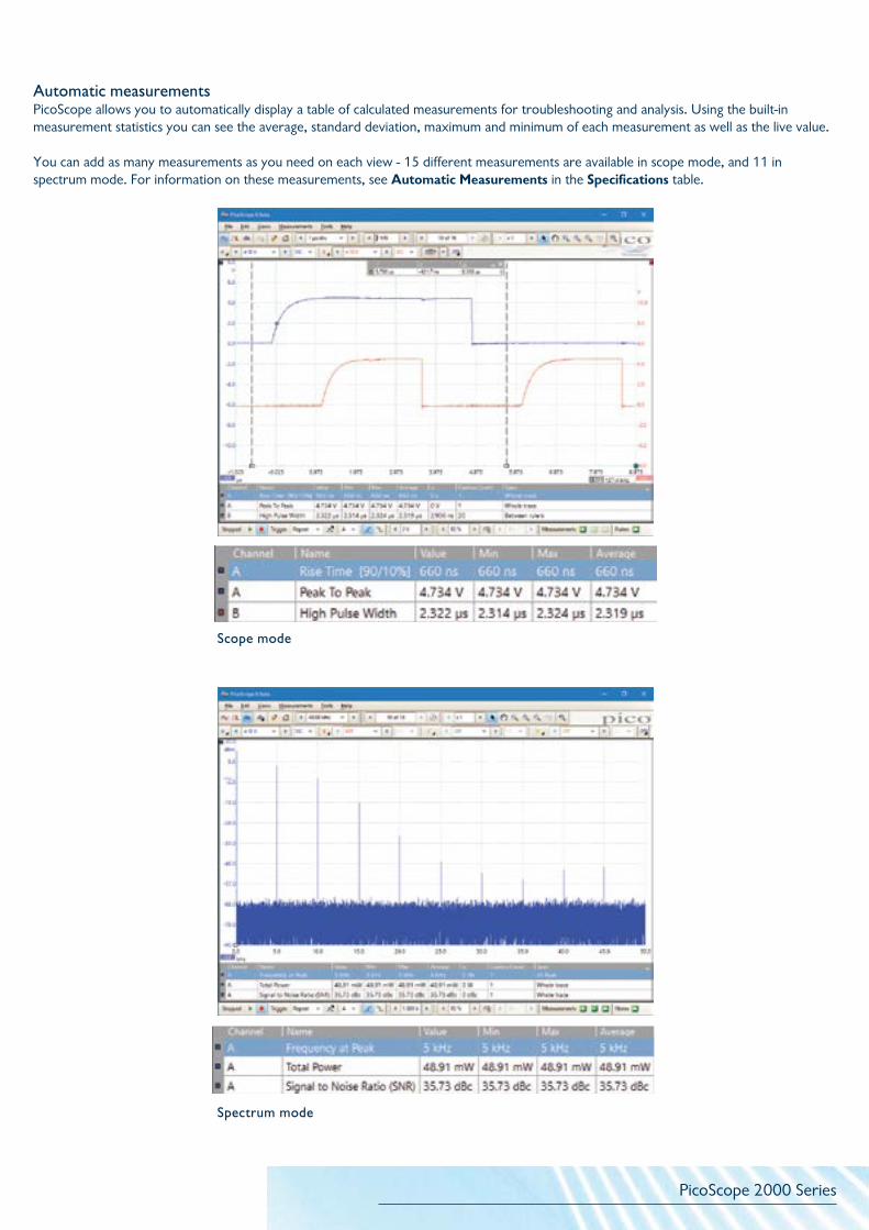
Automatic measurementsPicoScope allows you to automatically display a table of calculated measurements for troubleshooting and analysis. Using the built-in measurement statistics you can see the average, standard deviation, maximum and minimum of each measurement as well as the live value.
You can add as many measurements as you need on each view - 15 different measurements are available in scope mode, and 11 in spectrum mode. For information on these measurements, see Automatic Measurements in the Specifications table.
Scope mode
Spectrum mode

PicoScope 2000 Series
Serial decodingThe PicoScope 2000 Series oscilloscopes include serial decoding capability as standard. Display the decoded data in the format of your choice: as a graph, in a table, or both at once.
• Graph format shows the decoded data beneath the waveform on a common time axis, with error frames marked in red. You can zoom in on these frames to investigate noise or distortion. The data packets are broken down into their component fields, making it easier than ever to locate and identify problems signals, and each packet field is assigned a different color: in the CAN bus example below, the address is colored orange, the DLC green and the data content indigo. Color coding is available in PicoScope 6.12 or later, available for download from www.picotech.com.
• Table format shows a list of the decoded frames, including the data and all flags and identifiers. You can set up filtering conditions to display only the frames you are interested in, search for frames with specified properties, or define a start pattern to signal when the program should list the data.
It is also possible to link decoded numeric data to user-defined text strings, for ease of reading.
With the PicoScope 2000 Series, you can decode up to 15 serial protocols, including 1-Wire, CAN, I2C, I2S, LIN, SENT, SPI and UART/RS-232, depending on the bandwidth and sampling rate of the oscilloscope model. Please see the specification table for the full list.
PicoScope also includes options to import and export the decoded data using a Microsoft Excel spreadsheet.
Serial decoding for digital signalsThe PicoScope 2000 Series MSO models bring extra power to the serial decoding features. You can decode serial data on all analog and digital inputs simultaneously, giving you up to 18 channels of data with any combination of serial protocols. For example, you can decode multiple SPI, I²C, CAN bus, LIN bus and FlexRay signals all at the same time!

PicoScope 2000 Series
Waveform buffer and navigatorEver spotted a glitch on a waveform, but by the time you’ve stopped the scope it’s gone? With PicoScope you no longer need to worry about missing glitches or other transient events. PicoScope can store the last ten thousand waveforms in its circular waveform buffer.
The buffer navigator provides an efficient way of navigating and searching through waveforms, effectively letting you turn back time. Tools such as mask limit testing can also be used to scan through each waveform in the buffer looking for mask violations.
Mask limit testingPicoScope allows you to draw a mask around any signal with user-defined tolerances. This has been designed specifically for production and debugging environments, enabling you to compare signals. Simply capture a known good signal, draw a mask around it, and then attach the system under test. PicoScope will capture any intermittent glitches and can show a failure count and other statistics in the Measurements window.
The numerical and graphical mask editors can be used separately or in combination, allowing you to enter accurate mask specifications, modify existing masks, and import and export masks as files.
High-speed data acquisition and digitizingThe supplied drivers and software development kit (SDK) allow you to both write your own software and interface to popular third-party software packages such as National Instruments LabVIEW and MathWorks MATLAB.
The drivers support data streaming, a mode that captures gap-free continuous data over the USB port directly to the PC’s RAM or hard disk at rates of up to 1 MS/s (A models) or 9.6 MS/s (B models), so you are not limited by the size of the scope’s buffer memory. Sampling rates in streaming mode are subject to PC specifications and application loading.
Beta drivers are also available for use with Raspberry Pi, BeagleBone Black, and similar ARM-powered platforms. These drivers enable you to control your PicoScope using these small, single-board Linux computers.

PicoScope 2000 Series
Plot frequency against time with PicoScope 6All oscilloscopes can measure the frequency of a waveform, but often you need to know how that frequency changes over time, which is a difficult measurement to make.
The freq math function can do exactly this: in the example on the right, the top waveform’s frequency is being modulated by a ramp function, as plotted in the bottom waveform.
There is an additional math function to plot duty cycle in a similar way.
Math channelsWith PicoScope 6 you can perform a variety of mathematical calculations on your input signals and reference waveforms.
Use the built-in list for simple functions such as add and invert, or open the wizard and create complex functions involving trigonometry, exponentials, logarithms, statistics, integrals and derivatives.

PicoScope 2000 Series
VIEW your waveform with a low-cost USB-powered oscilloscope.
All standard PicoScope features are included: automatic measurements, serial decoding, persistence displays, mask limit testing, spectrum analysis, arbitrary waveform generator and more.
2-channel oscilloscopes
Model PicoScope 2204A
PicoScope 2205A
PicoScope 2206B
PicoScope 2207B
PicoScope 2208B
Bandwidth 10 MHz 25 MHz 50 MHz 70 MHz 100 MHz
Maximum sampling rate 100 MS/s 200 MS/s 500 MS/s 1 GS/s 1 GS/s
Buffer memory 8 kS 16 kS 32 MS 64 MS 128 MS
AWG bandwidth 100 kHz 100 kHz 1 MHz 1 MHz 1 MHz
Price
$115*/$139 $199*/$225 $349 $499 $679
€95*/€119 €169*/€189 €299 €419 €579
£79*/£99 £139*/£159 £249 £349 £479
4-channel oscilloscopes
Model PicoScope 2405A
PicoScope 2406B
PicoScope 2407B
PicoScope 2408B
Bandwidth 25 MHz 50 MHz 70 MHz 100 MHz
Maximum sampling rate 500 MS/s 1 GS/s 1 GS/s 1 GS/s
Buffer memory 48 kS 32 MS 64 MS 128 MS
AWG bandwidth 1 MHz 1 MHz 1 MHz 1 MHz
Price
$449 $599 $829 $1125
€389 €509 €699 €949
£319 £419 £579 £789
Mixed-signal oscilloscopes2 analog + 16 digital inputs
Model PicoScope 2205A MSO
PicoScope 2206B MSO
PicoScope 2207B MSO
PicoScope 2208B MSO
Bandwidth 25 MHz 50 MHz 70 MHz 100 MHz
Maximum sampling rate 500 MS/s 1 GS/s 1 GS/s 1 GS/s
Buffer memory 48 kS 32 MS 64 MS 128 MS
AWG bandwidth 1 MHz 1 MHz 1 MHz 1 MHz
Price
$449 $609 $769 $999
€389 €519 €649 €849
£319 £429 £539 £699
ANALYZE your waveform with a high-performance USB-powered oscilloscope.
Deep memory allows you to capture over long time periods at high sampling rates. You can then zoom in on your data without having to recapture. This is essential when you need to analyze one-off events with detailed timing resolution.
The arbitrary waveform generator can store complex waveforms in its large memory buffer, allowing you to test your design with realistic inputs.
Quick selector
*Without probes.
PicoScope 2000 Series
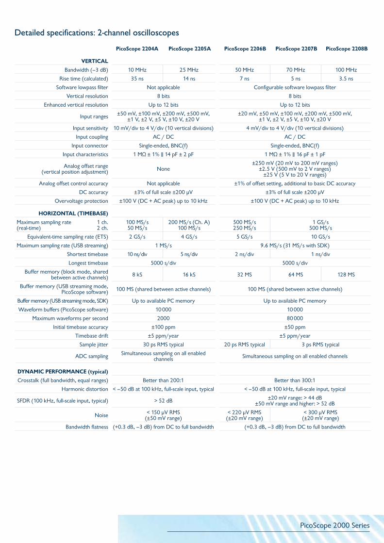
Detailed specifications: 2-channel oscilloscopes
PicoScope 2204A PicoScope 2205A PicoScope 2206B PicoScope 2207B PicoScope 2208B
VERTICAL
Bandwidth (–3 dB) 10 MHz 25 MHz 50 MHz 70 MHz 100 MHz
Rise time (calculated) 35 ns 14 ns 7 ns 5 ns 3.5 ns
Software lowpass filter Not applicable Configurable software lowpass filter
Vertical resolution 8 bits 8 bits
Enhanced vertical resolution Up to 12 bits Up to 12 bits
Input ranges ±50 mV, ±100 mV, ±200 mV, ±500 mV, ±1 V, ±2 V, ±5 V, ±10 V, ±20 V
±20 mV, ±50 mV, ±100 mV, ±200 mV, ±500 mV, ±1 V, ±2 V, ±5 V, ±10 V, ±20 V
Input sensitivity 10 mV/div to 4 V/div (10 vertical divisions) 4 mV/div to 4 V/div (10 vertical divisions)
Input coupling AC / DC AC / DC
Input connector Single-ended, BNC(f) Single-ended, BNC(f)
Input characteristics 1 MΩ ± 1% ∥ 14 pF ± 2 pF 1 MΩ ± 1% ∥ 16 pF ± 1 pF
Analog offset range (vertical position adjustment) None
±250 mV (20 mV to 200 mV ranges)±2.5 V (500 mV to 2 V ranges)
±25 V (5 V to 20 V ranges)
Analog offset control accuracy Not applicable ±1% of offset setting, additional to basic DC accuracy
DC accuracy ±3% of full scale ±200 μV ±3% of full scale ±200 μV
Overvoltage protection ±100 V (DC + AC peak) up to 10 kHz ±100 V (DC + AC peak) up to 10 kHz
HORIZONTAL (TIMEBASE)
Maximum sampling rate 1 ch.(real-time) 2 ch.
100 MS/s50 MS/s
200 MS/s (Ch. A)100 MS/s
500 MS/s250 MS/s
1 GS/s500 MS/s
Equivalent-time sampling rate (ETS) 2 GS/s 4 GS/s 5 GS/s 10 GS/s
Maximum sampling rate (USB streaming) 1 MS/s 9.6 MS/s (31 MS/s with SDK)
Shortest timebase 10 ns/div 5 ns/div 2 ns/div 1 ns/div
Longest timebase 5000 s/div 5000 s/div
Buffer memory (block mode, shared between active channels) 8 kS 16 kS 32 MS 64 MS 128 MS
Buffer memory (USB streaming mode, PicoScope software) 100 MS (shared between active channels) 100 MS (shared between active channels)
Buffer memory (USB streaming mode, SDK) Up to available PC memory Up to available PC memory
Waveform buffers (PicoScope software) 10 000 10 000
Maximum waveforms per second 2000 80 000
Initial timebase accuracy ±100 ppm ±50 ppm
Timebase drift ±5 ppm/year ±5 ppm/year
Sample jitter 30 ps RMS typical 20 ps RMS typical 3 ps RMS typical
ADC sampling Simultaneous sampling on all enabled channels Simultaneous sampling on all enabled channels
DYNAMIC PERFORMANCE (typical)
Crosstalk (full bandwidth, equal ranges) Better than 200:1 Better than 300:1
Harmonic distortion < –50 dB at 100 kHz, full-scale input, typical < –50 dB at 100 kHz, full-scale input, typical
SFDR (100 kHz, full-scale input, typical) > 52 dB ±20 mV range: > 44 dB ±50 mV range and higher: > 52 dB
Noise < 150 µV RMS (±50 mV range)
< 220 µV RMS (±20 mV range)
< 300 µV RMS (±20 mV range)
Bandwidth flatness (+0.3 dB, –3 dB) from DC to full bandwidth (+0.3 dB, –3 dB) from DC to full bandwidth

PicoScope 2000 Series
Detailed specifications: 2-channel oscilloscopes (continued)
PicoScope 2204A PicoScope 2205A PicoScope 2206B PicoScope 2207B PicoScope 2208B
TRIGGERING
Sources Ch A, Ch B Ch A, Ch B
Trigger modes None, auto, repeat, single None, auto, repeat, single, rapid (segmented memory)
Advanced triggersEdge, window, pulse width, window pulse width, dropout, window dropout, interval,
logic
Edge, window, pulse width, window pulse width, dropout, window dropout, interval, runt pulse, logic
Trigger types, ETS Rising or falling edge Rising or falling edge (available on Ch A only)
Segmented memory buffers (SDK) N/A 128 000 256 000 500 000
Segmented memory buffers (PicoScope software) N/A 10 000
Trigger sensitivity, real-time Digital triggering provides 1 LSB accuracy up to full bandwidth Digital triggering provides 1 LSB accuracy up to full bandwidth
Trigger sensitivity, ETS 10 mV p-p, typical, at full bandwidth 10 mV p-p, typical, at full bandwidth
Maximum pre-trigger capture 100% of capture size 100% of capture size
Maximum post-trigger delay 4 billion samples 4 billion samples
Trigger rearm time PC-dependent < 2 μs at 500 MS/s sampling rate < 1 µs at 1 GS/s sampling rate
Maximum trigger rate PC-dependent
10 000 waveforms in a 12 ms burst, at 500 MS/s sampling
rate, typical
10 000 waveforms in a 6 ms burst, at 1 GS/s sampling rate, typical

PicoScope 2000 Series
Detailed specifications: 4-channel oscilloscopes
PicoScope 2405A
PicoScope 2406B
PicoScope 2407B
PicoScope 2408B
VERTICAL
Bandwidth (–3 dB) 25 MHz 50 MHz 70 MHz 100 MHz
Rise time (calculated) 14 ns 7 ns 5 ns 3.5 ns
Software lowpass filter Not applicable Configurable lowpass filter
Vertical resolution 8 bits 8 bits
Enhanced vertical resolution Up to 12 bits Up to 12 bits
Input ranges±20 mV, ±50 mV, ±100 mV,
±200 mV, ±500 mV, ±1 V, ±2 V, ±5 V, ±10 V, ±20 V
±20 mV, ±50 mV, ±100 mV, ±200 mV, ±500 mV, ±1 V, ±2 V, ±5 V, ±10 V, ±20 V
Input sensitivity 4 mV/div to 4 V/div (10 vertical divisions) 4 mV/div to 4 V/div (10 vertical divisions)
Input coupling AC / DC AC / DC
Input characteristics 1 MΩ ± 1% ∥ 16 pF ± 1 pF 1 MΩ ± 1% ∥ 16 pF ± 1 pF
Input connector Single-ended, BNC(f) Single-ended, BNC(f)
Analog offset range (vertical position adjustment)
±250 mV (20 mV to 200 mV ranges)±2.5 V (500 mV to 2 V ranges)
±25 V (5 V to 20 V ranges)
±250 mV (20 mV to 200 mV ranges)±2.5 V (500 mV to 2 V ranges)
±25 V (5 V to 20 V ranges)
Analog offset control accuracy ±1% of offset setting, additional to basic DC accuracy ±1% of offset setting, additional to basic DC accuracy
DC accuracy ±3% of full scale ±200 μV ±3% of full scale ±200 μV
Overvoltage protection ±100 V (DC + AC peak) up to 10 kHz ±100 V (DC + AC peak) up to 10 kHz
HORIZONTAL (TIMEBASE)
Maximum sampling rate 1 ch.(real-time) 2 ch.
3 or 4 ch.
500 MS/s250 MS/s125 MS/s
1 GS/s500 MS/s250 MS/s
Equivalent-time sampling rate (ETS) 5 GS/s 10 GS/s
Maximum sampling rate (USB streaming) 1 MS/s (5 MS/s with SDK) 9.6 MS/s (31 MS/s with SDK)
Shortest timebase 2 ns/div 2 ns/div 1 ns/div
Longest timebase 5000 s/div 5000 s/div
Buffer memory (block mode, shared between active channels) 48 kS 32 MS 64 MS 128 MS
Buffer memory (USB streaming mode, PicoScope software)
100 MS (shared between active channels) 100 MS (shared between active channels)
Buffer memory (USB streaming mode, SDK) Up to available PC memory Up to available PC memory
Waveform buffers (PicoScope software) 10 000 10 000
Maximum waveforms per second 2000 80 000
Initial timebase accuracy ±50 ppm ±50 ppm
Timebase drift ±5 ppm/year ±5 ppm/year
Sample jitter 20 ps RMS, typical 3 ps RMS, typical
ADC sampling Simultaneous sampling on all enabled channels Simultaneous sampling on all enabled channels
DYNAMIC PERFORMANCE (typical)
Crosstalk (full bandwidth, equal ranges) Better than 300:1 Better than 300:1
Harmonic distortion < –50 dB at 100 kHz, full-scale input, typical < –50 dB at 100 kHz, full-scale input, typical
SFDR (100 kHz, full-scale input, typical) ±20 mV range: > 44 dB ±50 mV range and higher: > 52 dB
±20 mV range: > 44 dB ±50 mV range and higher: > 52 dB
Noise (±20 mV range) <150 µV RMS < 220 μV RMS < 300 μV RMS
Bandwidth flatness (+0.3 dB, –3 dB) from DC to full bandwidth, typical (+0.3 dB, –3 dB) from DC to full bandwidth, typical

PicoScope 2000 Series
Detailed specifications: 4-channel oscilloscopes (continued)
PicoScope 2405A
PicoScope 2406B
PicoScope 2407B
PicoScope 2408B
TRIGGERING
Sources Ch A, Ch B, Ch C, Ch D Ch A, Ch B, Ch C, Ch D
Trigger modes None, auto, repeat, single, rapid (segmented memory) None, auto, repeat, single, rapid (segmented memory)
Advanced triggersEdge, window, pulse width, window
pulse width, dropout, window dropout, interval, runt pulse, logic
Edge, window, pulse width, window pulse width, dropout, window dropout, interval, runt pulse, logic
Trigger types, ETS Rising or falling edge (available on Ch A only) Rising or falling edge (available on Ch A only)
Segmented memory buffers (SDK) 96 128 000 256 000 500 000
Segmented memory buffers (PicoScope software) 96 10 000
Trigger sensitivity, real-time Digital triggering provides 1 LSB accuracy up to full bandwidth Digital triggering provides 1 LSB accuracy up to full bandwidth
Trigger sensitivity, ETS 10 mV p-p, typical, at full bandwidth 10 mV p-p, typical, at full bandwidth
Maximum pre-trigger capture 100% of capture size 100% of capture size
Maximum post-trigger delay 4 billion samples 4 billion samples
Trigger rearm time < 2 μs at 500 MS/s sampling rate < 1 μs at 1 GS/s sampling rate
Maximum trigger rate 96 waveforms in a 192 µs burst, at 500 MS/s sampling rate, typical 10 000 waveforms in a 6 ms burst, at 1 GS/s sampling rate, typical

PicoScope 2000 Series
Detailed specifications: mixed-signal oscilloscopes
PicoScope 2205A MSO
PicoScope 2206B MSO
PicoScope 2207B MSO
PicoScope 2208B MSO
VERTICAL (ANALOG INPUTS)
Input channels 2 2
Bandwidth (–3 dB) 25 MHz 50 MHz 70 MHz 100 MHz
Rise time (calculated) 14 ns 7 ns 5 ns 3.5 ns
Software lowpass filter Not applicable Configurable software lowpass filter
Vertical resolution 8 bits 8 bits
Enhanced vertical resolution Up to 12 bits Up to 12 bits
Input ranges±20 mV, ±50 mV, ±100 mV,
±200 mV, ±500 mV, ±1 V, ±2 V, ±5 V, ±10 V, ±20 V
±20 mV, ±50 mV, ±100 mV, ±200 mV, ±500 mV, ±1 V, ±2 V, ±5 V, ±10 V, ±20 V
Input sensitivity 4 mV/div to 4 V/div (10 vertical divisions) 4 mV/div to 4 V/div (10 vertical divisions)
Input coupling AC / DC AC / DC
Input connector Single-ended, BNC(f) Single-ended, BNC(f)
Input characteristics 1 MΩ ± 1% ∥ 16 pF ± 1 pF 1 MΩ ± 1% ∥ 16 pF ± 1 pF
Analog offset range (vertical position adjustment)
±250 mV (20 mV to 200 mV ranges)±2.5 V (500 mV to 2 V ranges)
±25 V (5 V to 20 V ranges)
±250 mV (20 mV to 200 mV ranges)±2.5 V (500 mV to 2 V ranges)
±25 V (5 V to 20 V ranges)
Analog offset control accuracy ±1% of offset setting, additional to basic DC accuracy ±1% of offset setting, additional to basic DC accuracy
DC accuracy ±3% of full scale ±200 μV ±3% of full scale ±200 μV
Overvoltage protection ±100 V (DC + AC peak) up to 10 kHz ±100 V (DC + AC peak) up to 10 kHz
VERTICAL (DIGITAL INPUTS)
Input channels 16 (two 8-bit ports) 16 (two 8-bit ports)
Input connector 2.54 mm pitch, 10 x 2 way connector 2.54 mm pitch, 10 x 2 way connector
Maximum input frequency 100 MHz (200 Mb/s) 100 MHz (200 Mb/s)
Minimum detectable pulse width 5 ns 5 ns
Input impedance 200 kΩ ±2% ∥ 8 pF ±2 pF 200 kΩ ±2% ∥ 8 pF ±2 pF
Input dynamic range ±20 V ±20 V
Threshold range ±5 V ±5 V
Threshold grouping Two independent threshold controls. Port 0: D0 to D7, Port 1: D8 to D15
Two independent threshold controls. Port 0: D0 to D7, Port 1: D8 to D15
Threshold selection TTL, CMOS, ECL, PECL, user-defined TTL, CMOS, ECL, PECL, user-defined
Port threshold accuracy ±350 mV (inclusive of hysteresis) ±350 mV (inclusive of hysteresis)
Hysteresis < ±250 mV < ±250 mV
Minimum input voltage swing 500 mV pk-pk 500 mV pk-pk
Channel-to-channel skew 2 ns, typical 2 ns, typical
Minimum input slew rate 10 V/µs 10 V/µs
Overvoltage protection ±50 V ±50 V

PicoScope 2000 Series
Detailed specifications: mixed-signal oscilloscopes (continued)
PicoScope 2205A MSO
PicoScope 2206B MSO
PicoScope 2207B MSO
PicoScope 2208B MSO
HORIZONTAL (TIMEBASE)
Maximum sampling rate 1 analog ch.(real-time) 1 digital port2 analog ch., 2 digital ports or 1 of each Other
500 MS/s500 MS/s250 MS/s250 MS/s
1 GS/s500 MS/s500 MS/s250 MS/s
Equivalent-time sampling rate (ETS) 5 GS/s 10 GS/s
Maximum sampling rate (USB streaming) 1 MS/s (5 MS/s with SDK) 9.6 MS/s (31 MS/s with SDK)
Shortest timebase 2 ns/div 2 ns/div 1 ns/div
Longest timebase 5000 s/div 5000 s/div
Buffer memory (block mode, shared between active channels) 48 kS 32 MS 64 MS 128 MS
Buffer memory (USB streaming mode, PicoScope software)
100 MS (shared between active channels) 100 MS (shared between active channels)
Buffer memory (USB streaming mode, SDK) Up to available PC memory Up to available PC memory
Waveform buffers (PicoScope software) 10 000 10 000
Maximum waveforms per second 2000 80 000
Initial timebase accuracy ±50 ppm ±50 ppm
Timebase drift ±5 ppm/year ±5 ppm/year
Sample jitter 20 ps RMS, typical 3 ps RMS, typical
ADC sampling Simultaneous sampling on all enabled channels Simultaneous sampling on all enabled channels
DYNAMIC PERFORMANCE (typical)
Crosstalk (full bandwidth, equal ranges) Better than 300:1 Better than 300:1
Harmonic distortion < –50 dB at 100 kHz, full-scale input, typical < –50 dB at 100 kHz, full-scale input, typical
SFDR (100 kHz, full-scale input, typical) ±20 mV range: > 44 dB ±50 mV range and higher: > 52 dB
±20 mV range: > 44 dB ±50 mV range and higher: > 52 dB
Noise (±20 mV range) < 150 µV RMS < 220 μV RMS < 300 μV RMS
Bandwidth flatness (+0.3 dB, –3 dB) from DC to full bandwidth, typical (+0.3 dB, –3 dB) from DC to full bandwidth, typical
TRIGGERING
Sources Ch A, Ch B, Digital 0–15 Ch A, Ch B, Digital 0–15
Trigger modes None, auto, repeat, single, rapid (segmented memory) None, auto, repeat, single, rapid (segmented memory)
Advanced triggers (analog inputs)
Edge, window, pulse width, window pulse width, dropout, window
dropout, interval, runt pulse, logic
Edge, window, pulse width, window pulse width, dropout, window dropout, interval, runt pulse, logic
Advanced triggers (digital inputs)
Edge, pulse width, dropout, interval, logic, pattern, mixed signal Edge, pulse width, dropout, interval, logic, pattern, mixed signal
Trigger types, ETS Rising or falling edge (available on Ch A only) Rising or falling edge (available on Ch A only)
Segmented memory buffers (SDK) 96 128 000 256 000 500 000
Segmented memory buffers (PicoScope software) 96 10 000
Trigger sensitivity, real-time (analog channels)
Digital triggering provides 1 LSB accuracy up to full bandwidth Digital triggering provides 1 LSB accuracy up to full bandwidth
Trigger sensitivity, ETS (analog channels) 10 mV p-p, typical, at full bandwidth 10 mV p-p, typical, at full bandwidth
Maximum pre-trigger capture 100% of capture size 100% of capture size
Maximum post-trigger delay 4 billion samples 4 billion samples
Trigger rearm time < 2 μs at 500 MS/s sampling rate < 1 μs at 1 GS/s sampling rate
Maximum trigger rate 96 waveforms in a 192 µs burst, at 500 MS/s sampling rate, typical 10 000 waveforms in a 6 ms burst, at 1 GS/s sampling rate, typical

PicoScope 2000 Series
Common specifications
SPECTRUM ANALYZERFrequency range DC to analog bandwidth of oscilloscope
Display modes Magnitude, average, peak hold
Windowing functions Rectangular, Gaussian, triangular, Blackman, Blackman-Harris, Hamming, Hann, flat-top
Number of FFT points Selectable from 128 to half available buffer memory in powers of 2, up to a maximum of 1 048 576 points
MATH CHANNELS
Functions
−x, x+y, x−y, x*y, x/y, x^y, sqrt, exp, ln, log, abs, norm, sign, sin, cos, tan, arcsin, arccos, arctan, sinh, cosh, tanh, freq, derivative, integral, min, max, average, peak, delay, duty, highpass, lowpass, bandpass, bandstop
Operands A, B (input channels), C, D (input channels, 4-channel models only), T (time), reference waveforms, constants, pi, digital channels (MSO models only)
AUTOMATIC MEASUREMENTS
Scope mode AC RMS, true RMS, frequency, cycle time, duty cycle, DC average, falling rate, rising rate, low pulse width, high pulse width, fall time, rise time, minimum, maximum, peak to peak
Spectrum mode Frequency at peak, amplitude at peak, THD dB, SNR, SINAD, SFDR, total power, average amplitude at peak, THD %, THD+N, IMD,
Statistics Minimum, maximum, average and standard deviation
SERIAL DECODING
Protocols 1-Wire, ARINC 429, CAN, DCC, DMX512, FlexRay, Ethernet 10Base-T, USB 1.1, I²C, I²S, LIN, PS/2, SPI, SENT, UART/RS-232 (subject to bandwidth and sampling rate of chosen oscilloscope model)
MASK LIMIT TESTINGStatistics Pass/fail, failure count, total count
DISPLAYInterpolation Linear or sin(x)/x
Persistence modes Digital color, analog intensity, custom, fast or none
Signal generator specifications: all models
PicoScope 2204APicoScope 2205A
PicoScope 2405APicoScope 2205A MSO All B models
FUNCTION GENERATOR
Standard output signals Sine, square, triangle, DC voltage, ramp, sinc, Gaussian, half-sine Sine, square, triangle, DC voltage, ramp, sinc, Gaussian, half-sine
Pseudorandom output signals None White noise, PRBS
Standard signal frequency DC to 100 kHz DC to 1 MHz
Sweep modes Up, down, dual with selectable start/stop frequencies and increments Up, down, dual with selectable start/stop frequencies and increments
Triggering None Free-run or up to 1 billion waveform cycles or frequency sweeps. Triggered from scope trigger or manually.
Output frequency accuracy Oscilloscope timebase accuracy ± output frequency resolution Oscilloscope timebase accuracy ± output frequency resolution
Output frequency resolution < 0.02 Hz < 0.01 Hz
Output voltage range ±2 V ±2 V
Output adjustments Any amplitude and offset within ±2 V range Any amplitude and offset within ±2 V range
Amplitude flatness (typical) < 1 dB to 100 kHz < 0.5 dB to 1 MHz
DC accuracy ±1% of full scale ±1% of full scale
SFDR (typical) > 55 dB at 1 kHz full-scale sine wave > 60 dB at 10 kHz full-scale sine wave
Output characteristics Front panel BNC, 600 Ω output impedance Front panel BNC, 600 Ω output impedance
Overvoltage protection ±20 V ±20 V
ARBITRARY WAVEFORM GENERATORUpdate rate 1.548 MHz 20 MHz
Buffer size 4 kS 8 kS 32 kS
Resolution 12 bits 12 bits
Bandwidth > 100 kHz > 1 MHz
Rise time (10% to 90%) < 2 µs < 120 ns

PicoScope 2000 Series
Your PicoScope 2000 Series oscilloscope comes with the following items:
• USB 2.0 (USB 3.0/3.1 compatible) cable• Two or four x1/x10 passive probes (except kits specified as without probes; 150 MHz TA132 probes illustrated below)• Digital input cable (MSO models only)• 20 logic test clips (MSO models only)• Quick Start Guide• Software and reference CD
Common specifications (continued)
GENERALPC connectivity USB 2.0 (USB 3.0 compatible). USB cable included.
Power requirements Powered from USB portDimensions
(including connectors and feet)142 x 92 x 18.8 mm (PicoScope 2204A and 2205A only)
130 x 104 x 18.8 mm (all other models, including PicoScope 2205A MSO)Weight < 0.2 kg (7 oz)
Temperature range, operating 0 °C to 50 °C Temperature range, operating, for
stated accuracy 15 °C to 30 °C
Temperature range, storage –20 °C to +60 °C
Humidity range, operating 5% to 80% RH non-condensing
Humidity range, storage 5% to 95% RH non-condensing
Altitude range up to 2000 m
Pollution degree 2
Safety approvals Designed to EN 61010-1:2010
Environmental approvals RoHS, WEEE
EMC approvals Tested to meet EN61326-1:2013 and FCC Part 15 Subpart B
Software includedPicoScope 6 for Microsoft Windows 7, 8 and 10; 32-bit and 64-bit
SDK for Windows 7, 8 and 10; 32-bit and 64-bitExample programs (C, Microsoft Excel VBA, LabVIEW)
Free software available for download PicoScope 6 (beta) for Linux and OS XSDK (beta) for Linux and OS X
Languages supportedSimplified Chinese, Czech, Danish, Dutch, English, Finnish, French,
German, Greek, Hungarian, Italian, Japanese, Korean, Norwegian, Polish, Portuguese, Romanian, Russian, Spanish, Swedish, Turkish

Ordering information
OscilloscopesORDER CODE DESCRIPTION USD* EUR* GBP*
PP917 PicoScope 2204A 10 MHz 2-channel oscilloscope without probes 115 95 79
PP906 PicoScope 2204A 10 MHz 2-channel oscilloscope 139 119 99
PP966 PicoScope 2205A 25 MHz 2-channel oscilloscope without probes 199 169 139
PP907 PicoScope 2205A 25 MHz 2-channel oscilloscope 225 189 159
PQ012 PicoScope 2206B 50 MHz 2-channel oscilloscope 349 299 249
PQ013 PicoScope 2207B 70 MHz 2-channel oscilloscope 499 419 349
PQ014 PicoScope 2208B 100 MHz 2-channel oscilloscope 679 579 479
PQ015 PicoScope 2405A 25 MHz 4-channel oscilloscope 449 389 319
PQ016 PicoScope 2406B 50 MHz 4-channel oscilloscope 599 509 419
PQ017 PicoScope 2407B 70 MHz 4-channel oscilloscope 829 699 579
PQ018 PicoScope 2408B 100 MHz 4-channel oscilloscope 1125 949 789
PQ008 PicoScope 2205A MSO 25 MHz 2+16 channel mixed-signal oscilloscope 449 389 319
PQ009 PicoScope 2206B MSO 50 MHz 2+16 channel mixed-signal oscilloscope 609 519 429
PQ010 PicoScope 2207B MSO 70 MHz 2+16 channel mixed-signal oscilloscope 769 649 539
PQ011 PicoScope 2208B MSO 100 MHz 2+16 channel mixed-signal oscilloscope 999 849 699
Replacement accessoriesORDER CODE DESCRIPTION USD* EUR* GBP*
MI00760 MHz passive probe (supplied in oscilloscope kits with up to 50 MHz bandwidth)
25 21 18
TA132150 MHz passive probe (supplied with 70 MHz and 100 MHz oscilloscopes)
33 28 23
TA136 20-way 25 cm digital cable (suitable for MSOs only) 17 14 12
TA139 Pack of 10 logic test clips (suitable for MSOs only) 30 26 21
*Prices are correct at the time of publication. Sales taxes not included. Please contact Pico Technology for the latest prices before ordering.
UK headquarters:Pico TechnologyJames HouseColmworth Business ParkSt. NeotsCambridgeshirePE19 8YP United Kingdom
+44 (0) 1480 396 395 +44 (0) 1480 396 296 [email protected]
Errors and omissions excepted. Pico Technology and PicoScope are internationally registered trade marks of Pico Technology Ltd.
Some illustrations in this data sheet show beta software. The software supplied with the product meets the stated specifications but may differ slightly in its graphical appearance.
MM071.en-3. Copyright © 2016 Pico Technology Ltd. All rights reserved. www.picotech.com
US headquarters:Pico Technology320 N Glenwood BlvdTylerTexas 75702United States
+1 800 591 2796 +1 620 272 0981 [email protected]
PicoScope 3000 Series
General purpose 2- and 4-channel
PicoScope 5000 Series
Flexible resolution8 to 16 bits
PicoScope 6000 Series
High performanceUp to 1 GHz
PicoScope 9000 Series
Sampling scopesand TDR to 20 GHz
PicoScope 4000 SeriesHigh precision 12 to 16 bits
More oscilloscopes in the PicoScope range...