Embed Size (px)
Citation preview
For Your Safe Flight Page 1
Pilot’s Guide
Engine Data Management
EDM-900
Primary
TSO/STC Copyright 2011 J.P. Instruments, Inc.
All Rights Reserved
J.P. INSTRUMENTS INC.
Information: P. O. Box 7033 Huntington Beach, CA 92646
Factory: 3185-B Airway Ave. Costa Mesa, CA 92626 (714) 557-3805 Fax (714) 557-9840
www.jpinstruments.com
Printed in the United States of America Rev B
Page 2 Engine Data Management
Table of Contents
Section 1 - Section-1 Getting Started 5 View Angle 5 Rotation 7 Fuel Flow Computer Basics (independent of fuel quantity) 7 Display Screen Basics 8 Horizontal Display Mode 8 Vertical Display Mode 9 Remote Annunciate Light Basics 9 RPM and MAP Display Basics 10 Linear Bar Graph Display Basics 10 LeanFind Basics 12
Section 2 - Interpreting Data 13 Operation for each Phase of Flight 13 Typical Normal Measurements 15
Section 3 - Displays and Controls 18 Control Buttons 18 Scanner Displays 20 Additional Displays Hobbs, Revisions, and Alarm Limits 22 Dimming the Display 23
Section 4 - Operating Modes 23 Automatic Mode 23 Manual Mode 24
Section 5 - Lean Find 26 Lean Find Procedure—General Explanation 31 Expanded Leaning Procedures 34 Common Misapplications 35
Section 6 - Fuel Flow Operation 36 Fuel Management 36 Start Up Fuel 37 Resetting ‘USD’ 38 Trip Mode (Accumulate Trip Totalizer) 38 Scanner Fuel Flow Display Select 38
Section 7 - Alarms 39 Section 8 - Memory and Data Download 40
Downloading Data from the EDM 40 Transferring data from the USB Flash Drive to a PC 41
Section 9 - First Time Setup and Customization 41 Section 10 - Adjusting Manifold Pressure & %HP 46
Adjusting the HP Constant for Rich of Peak Operation 46 Adjusting the MAP 46 Adjusting the HP Value 47
Section 11 - Programming the Fuel Flow 48 Fuel Flow K factor 48 Programming Trip Mode 51 Setting the GPS Com Format 51
For Your Safe Flight ............................................... Page 3
Troubleshooting the EDM 53 Diagnostic Testing on Startup and During Flight 53 Diagnostic Messages 53
Section 12 - Appendices 55 Shock Cooling (CLD) 55 Navigation Data Formats 57 Navigation Data Ports for GPS Comm 57 Interface connections to selected GPS models 57
Section 13 - Technical Support 58
Page 4 Engine Data Management
Product Features
Hands-free, automatic scanning
Lean Find finds the first and last cylinder to peak with true peak detect—eliminates false peaks
Displays both leaned temperature below peak and peak Battery voltage with alarm Amperes (load or charge/discharge meter) Programmable alarm limits Exhaust Gas Temperatures (EGTs) to stable 1°F
resolution DIF low to high EGT with alarm Shock cooling monitored on every cylinder Fast response probes Non-volatile long term memory Records and stores data up to 30 hours Post-flight data retrieval Data retrieval software Oil pressure Oil temperature Turbine inlet temperature, if applicable (optional) Outside air temperature Compressor discharge temperature (optional) Carburetor temperature or induction temperature
(optional) Fuel pressure, if applicable Fuel level Voltage, Resistive or Capacitive (frequency) Fuel Flow
Solid-state rotor fuel flow transducer
Fuel quantity in gallons, kilograms, liters, or pounds
Low fuel quantity alarm
Low fuel time alarm
GPS interface
Instantaneous fuel flow rate
Total amount of fuel consumed
Total fuel remaining
Time to empty at the current fuel flow rate RPM and manifold pressure Automatically calculates percent horsepower Hobbs® timer Remote Auxiliary Display (RAD)
For Your Safe Flight ............................................... Page 5
Section 1 - Section-1 Getting Started
This is a summary of basic operation. Detailed descriptions of all operations appear later in this Pilot’s Guide.
EDM-900 primary instrument has preset alarm limits and cautionary ranges per the POH (user cannot change them) typically for the following measurements of: oil temperature, oil pressure, fuel pressure, fuel quantity, cylinder head temperature, turbine inlet temperature, manifold pressure, and RPM.
Note: Fuel quantity gauges must be calibrated to the aircraft and will not be functional until the fuel calibration process has been performed.
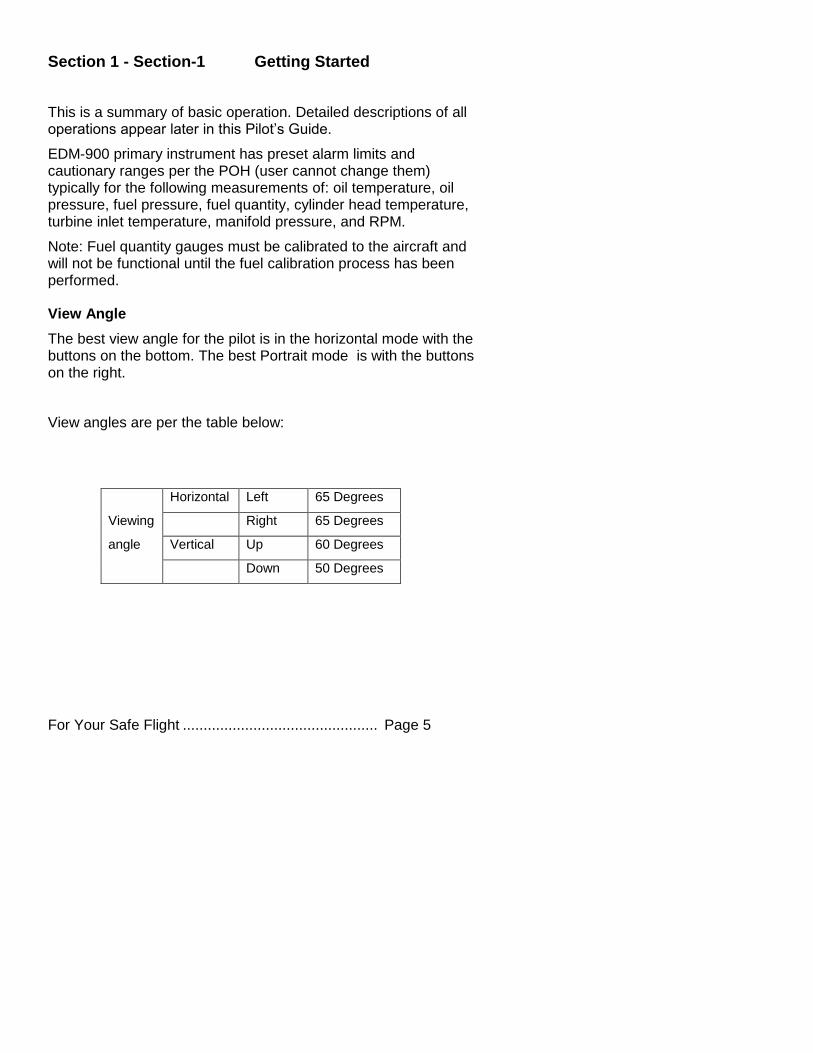
View Angle
The best view angle for the pilot is in the horizontal mode with the buttons on the bottom. The best Portrait mode is with the buttons on the right.
View angles are per the table below:
Horizontal Left 65 Degrees
Viewing Right 65 Degrees
angle Vertical Up 60 Degrees
Down 50 Degrees
Page 6 Engine Data Management
List of abbreviations and acronyms
Gauge Function Message Area
Alarm Abbreviation Primary Primary
Engine rotational speed RPM xxxx
Engine Manifold Pressure MAP xx.x in hg
Engine Cylinder Head Temp CHT2 xxx oF
Engine Oil Temperature O-T xxx oF
Engine Oil Pressure O-P xxx oF
Fuel Pressure F-P xx PSI
Fuel Flow to engine F-F xx.x GPH
Comp. Discharge Temp. CDT xxx oF
Turbine inlet Temp. Left side TIT-L xxxx oF
Turbine Inlet Temp. Right side TIT-R xxxx oF
Single Turbine Inlet Temp. TIT xxxx oF
Non-Primary Non-Primary
Exhaust Gas Temp. EGT2 xxxx oF
Shock Cooling of CHT CLD xx o/MIN
Differential Temp. of EGT DIF xx oF
Bus Voltage Volts xx.x
Amperage Load AMPS xx
Outside Air Temp. OAT xx oF
Estimated Time to Empty Est. T to E xx:xx H:M
Fuel used to date USED xx.x GAL
Estimated Remaining fuel Est. REM xx GAL
Estimated Fuel required to Waypoint Est. WP REQ xx GAL
Estimated Fuel Remaining at Waypoint
Est. WP RES xx GAL
Nautical Miles per Gallon ECON xx.x MPG
Brightness, Dim control DIM/BRT
For Your Safe Flight ............................................... Page 7
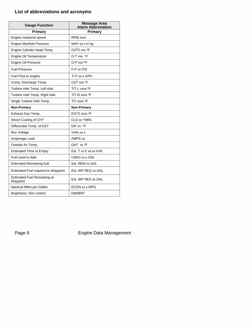
Rotation
Holding the step button in for 5 seconds, with the engine OFF, will produce the gray arrow. This arrow can be rotated to a new up position by tapping the LF button to rotate and then the STEP button for save. If you chose the one bad angle (Landscape mode with the buttons on top and the JPI logo upside down), return the instrument to JPI and JPI will rotate the screen with the buttons on the bottom.
Fuel Flow Computer Basics (independent of fuel quantity)
The fuel flow computer tracks the fuel flowing to the engine and computes various values based on this. At installation, then each time you refuel the aircraft, you must inform the EDM about how much useable fuel is onboard. This is done via the REFUEL function. See page 36 for detailed information
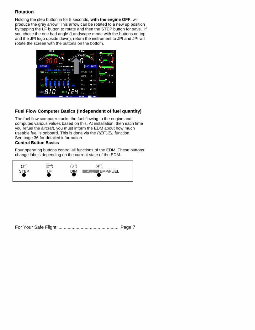
Control Button Basics
Four operating buttons control all functions of the EDM. These buttons change labels depending on the current state of the EDM.
STEP LF DIM
(3rd)
ALL /TEMP/FUEL
(1st) (2nd) (4th)
Page 8 Engine Data Management
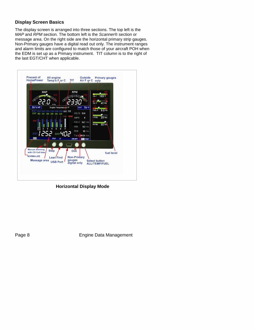
Display Screen Basics
The display screen is arranged into three sections. The top left is the MAP and RPM section. The bottom left is the Scanner® section or message area. On the right side are the horizontal primary strip gauges. Non-Primary gauges have a digital read out only. The instrument ranges and alarm limits are configured to match those of your aircraft POH when the EDM is set up as a Primary instrument. TIT column is to the right of the last EGT/CHT when applicable.
Horizontal Display Mode
For Your Safe Flight ............................................... Page 9
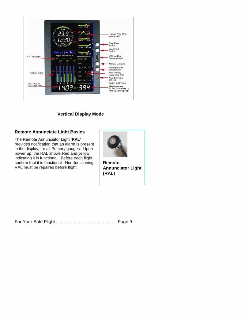
Vertical Display Mode
Remote Annunciate Light Basics
The Remote Annunciator Light ‘RAL’ provides notification that an alarm is present in the display, for all Primary gauges. Upon power up, the RAL shows Red and yellow indicating it is functional. Before each flight, confirm that it is functional. Non-functioning RAL must be repaired before flight.
Remote
Annunciator Light
(RAL)
Page 10 Engine Data Management
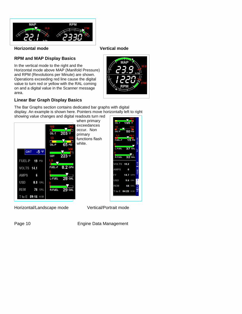
Horizontal mode Vertical mode
RPM and MAP Display Basics
In the vertical mode to the right and the Horizontal mode above MAP (Manifold Pressure) and RPM (Revolutions per Minute) are shown. Operations exceeding red line cause the digital value to turn red or yellow with the RAL coming on and a digital value in the Scanner message area.
Linear Bar Graph Display Basics
The Bar Graphs section contains dedicated bar graphs with digital display. An example is shown here. Pointers move horizontally left to right showing value changes and digital readouts turn red
when primary exceedances occur. Non primary functions flash white.
Horizontal/Landscape mode Vertical/Portrait mode
For Your Safe Flight ............................................. Page 11
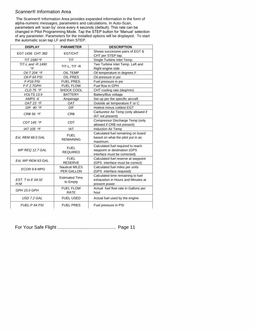
Scanner® Information Area
The Scanner® Information Area provides expanded information in the form of alpha-numeric messages, parameters and calculations. In Auto-Scan, parameters will ‘scan by’ once every 4 seconds (default). This rate can be changed in Pilot Programming Mode. Tap the STEP button for ‘Manual’ selection of any parameter. Parameters for the installed options will be displayed. To start the automatic scan tap LF and then STEP.
DISPLAY PARAMETER DESCRIPTION
EGT 1436 CHT 382 EGT/CHT Shows successive pairs of EGT &
CHT per STEP tap.
TIT 1580 oF TIT Single Turbine Inlet Temp.
TIT-L and -R 1490 oF
TIT-L, TIT -R Two Turbine Inlet Temp. Left and
Right engine side
Oil-T 204 oF OIL TEMP Oil temperature in degrees F
Oil-P 64 PSI OIL PRES Oil pressure in psi
F-P16 PSI FUEL PRES. Fuel pressure in psi
F-F 2.7GPH FUEL FLOW Fuel flow in GPH
CLD 75 oF SHOCK COOL CHT cooling rate (deg/min)
VOLTS 13.9 BATTERY Battery/Bus voltage
AMPS -6 Amperage Set up per the specific aircraft
OAT 23 oF OAT Outside air temperature F or C
DIF 40 oF DIF Hottest minus coldest EGT
CRB 56 oF CRB Carburetor Air Temp (only allowed if
IAT not present)
CDT 145 oF CDT Compressor Discharge Temp (only
allowed if CRB not present)
IAT 105 oF IAT Induction Air Temp
Est. REM 68.0 GAL FUEL
REMAINING
Calculated fuel remaining on board
based on what the pilot put in as
maximum.
WP REQ 12.7 GAL FUEL
REQUIRED
Calculated fuel required to reach
waypoint or destination (GPS
interface must be corrected)
Est. WP REM 63 GAL FUEL
RESERVE
Calculated fuel reserve at waypoint
(GPS interface must be correct)
ECON 9.8 MPG Nautical MILES
PER GALLON
Calculated fuel miles per units
(GPS interface required)
EST. T to E 04:32
H:M
Estimated Time
to Empty
Calculated time remaining to fuel
exhaustion in Hours and Minutes at
present power.
GPH 15.0 GPH FUEL FLOW
RATE
Actual fuel flow rate in Gallons per
hour
USD 7.2 GAL FUEL USED Actual fuel used by the engine
FUEL-P 64 PSI FUEL PRES Fuel pressure in PSI
Page 12 Engine Data Management
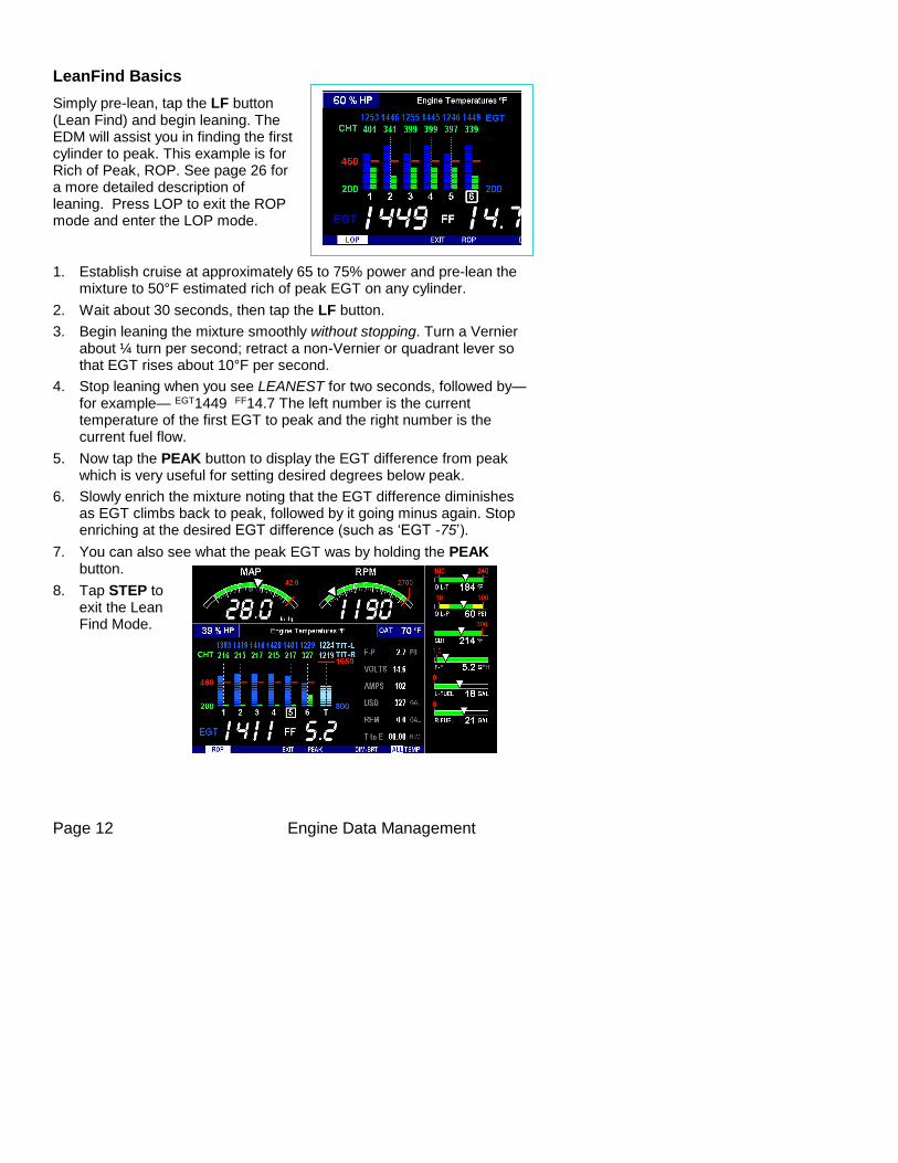
LeanFind Basics
Simply pre-lean, tap the LF button (Lean Find) and begin leaning. The EDM will assist you in finding the first cylinder to peak. This example is for Rich of Peak, ROP. See page 26 for a more detailed description of leaning. Press LOP to exit the ROP mode and enter the LOP mode.
1. Establish cruise at approximately 65 to 75% power and pre-lean the mixture to 50°F estimated rich of peak EGT on any cylinder.
2. Wait about 30 seconds, then tap the LF button.
3. Begin leaning the mixture smoothly without stopping. Turn a Vernier about ¼ turn per second; retract a non-Vernier or quadrant lever so that EGT rises about 10°F per second.
4. Stop leaning when you see LEANEST for two seconds, followed by—for example— EGT1449 FF14.7 The left number is the current temperature of the first EGT to peak and the right number is the current fuel flow.
5. Now tap the PEAK button to display the EGT difference from peak which is very useful for setting desired degrees below peak.
6. Slowly enrich the mixture noting that the EGT difference diminishes as EGT climbs back to peak, followed by it going minus again. Stop enriching at the desired EGT difference (such as ‘EGT -75’).
7. You can also see what the peak EGT was by holding the PEAK button.
8. Tap STEP to exit the Lean Find Mode.
For Your Safe Flight ............................................. Page 13
Section 2 - Interpreting Data
Operation for each Phase of Flight
(Worth adding to your run-up checklist)
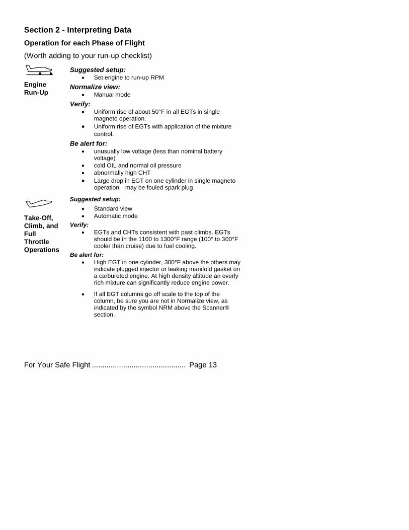
Engine
Run-Up
Suggested setup: Set engine to run-up RPM
Normalize view: Manual mode
Verify: Uniform rise of about 50°F in all EGTs in single
magneto operation.
Uniform rise of EGTs with application of the mixture
control.
Be alert for: unusually low voltage (less than nominal battery
voltage)
cold OIL and normal oil pressure
abnormally high CHT
Large drop in EGT on one cylinder in single magneto operation—may be fouled spark plug.
Take-Off,
Climb, and
Full
Throttle
Operations
Suggested setup:
Standard view
Automatic mode
Verify:
EGTs and CHTs consistent with past climbs. EGTs should be in the 1100 to 1300°F range (100° to 300°F cooler than cruise) due to fuel cooling.
Be alert for:
High EGT in one cylinder, 300°F above the others may indicate plugged injector or leaking manifold gasket on a carbureted engine. At high density altitude an overly rich mixture can significantly reduce engine power.
If all EGT columns go off scale to the top of the column, be sure you are not in Normalize view, as indicated by the symbol NRM above the Scanner® section.
Page 14 Engine Data Management
Cruise
After the engine is warmed up, use Lean Find to lean the mixture.
Suggested setup:
Normalize view
Automatic mode
Be alert for:
Uneven EGTs (injected engines). Make fine adjustments to throttle, then RPM, then mixture to level the display columns.
Abnormal patterns of EGTs and CHT. (see Engine
Diagnosis Chart on page 16).
Descent
Suggested setup:
Standard view
Manual mode
Be alert for:
CLD: shock cooling alarm is set to -60°F. Average cool rates of -40°F/minute to -50°F/minute are normal, depending on the engine size.
For Your Safe Flight ............................................. Page 15
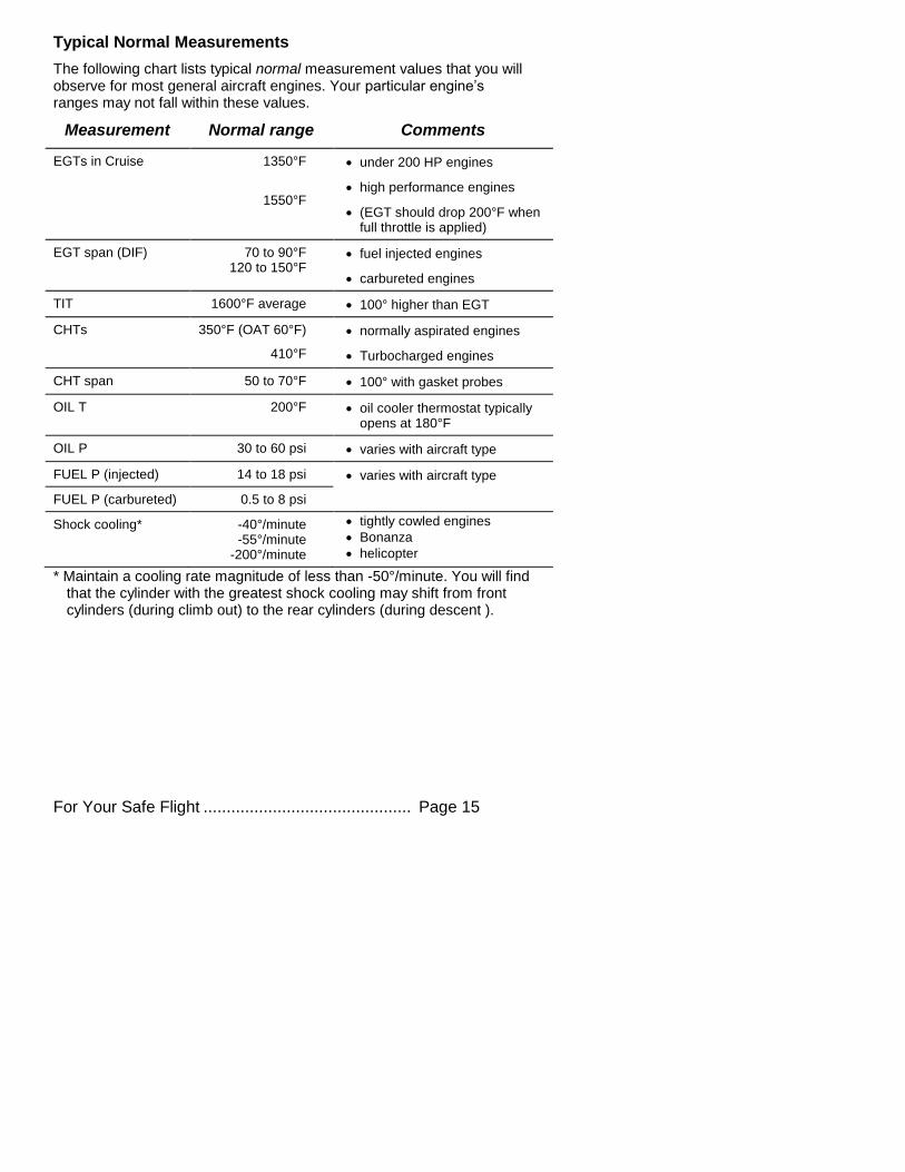
Typical Normal Measurements
The following chart lists typical normal measurement values that you will observe for most general aircraft engines. Your particular engine’s ranges may not fall within these values.
Measurement Normal range Comments
EGTs in Cruise 1350°F
1550°F
under 200 HP engines
high performance engines
(EGT should drop 200°F when full throttle is applied)
EGT span (DIF) 70 to 90°F 120 to 150°F
fuel injected engines
carbureted engines
TIT 1600°F average 100° higher than EGT
CHTs 350°F (OAT 60°F)
410°F
normally aspirated engines
Turbocharged engines
CHT span 50 to 70°F 100° with gasket probes
OIL T 200°F oil cooler thermostat typically opens at 180°F
OIL P 30 to 60 psi varies with aircraft type
FUEL P (injected) 14 to 18 psi varies with aircraft type
FUEL P (carbureted) 0.5 to 8 psi
Shock cooling* -40°/minute -55°/minute
-200°/minute
tightly cowled engines
Bonanza
helicopter
* Maintain a cooling rate magnitude of less than -50°/minute. You will find that the cylinder with the greatest shock cooling may shift from front cylinders (during climb out) to the rear cylinders (during descent ).
Page 16 Engine Data Management
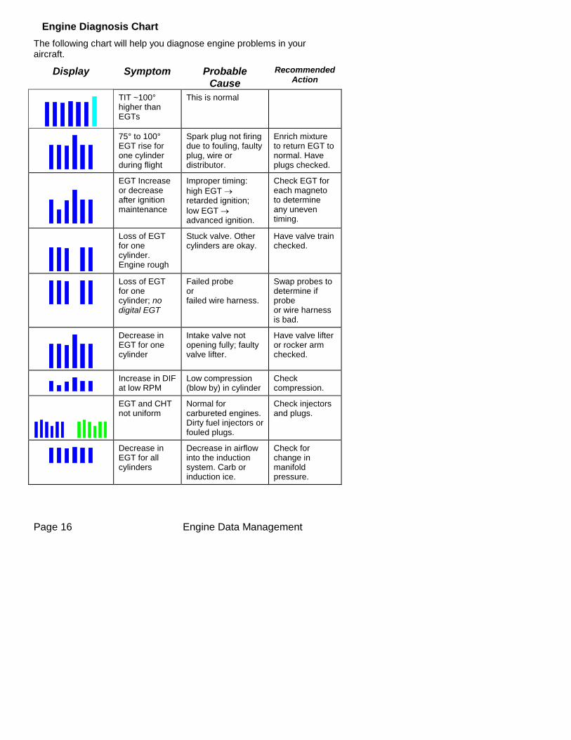
Engine Diagnosis Chart
The following chart will help you diagnose engine problems in your aircraft.
Display Symptom Probable
Cause
Recommended Action
TIT ~100° higher than EGTs
This is normal
75° to 100° EGT rise for one cylinder during flight
Spark plug not firing due to fouling, faulty plug, wire or distributor.
Enrich mixture to return EGT to normal. Have plugs checked.
EGT Increase or decrease after ignition maintenance
Improper timing:
high EGT retarded ignition;
low EGT advanced ignition.
Check EGT for each magneto to determine any uneven timing.
Loss of EGT for one cylinder. Engine rough
Stuck valve. Other cylinders are okay.
Have valve train checked.
Loss of EGT for one cylinder; no digital EGT
Failed probe or failed wire harness.
Swap probes to determine if probe or wire harness is bad.
Decrease in EGT for one cylinder
Intake valve not opening fully; faulty valve lifter.
Have valve lifter or rocker arm checked.
Increase in DIF at low RPM
Low compression (blow by) in cylinder
Check compression.
EGT and CHT not uniform
Normal for carbureted engines. Dirty fuel injectors or fouled plugs.
Check injectors and plugs.
Decrease in EGT for all cylinders
Decrease in airflow into the induction system. Carb or induction ice.
Check for change in manifold pressure.
For Your Safe Flight ............................................. Page 17
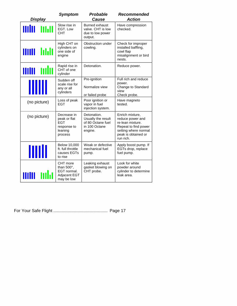
Display Symptom Probable
Cause
Recommended
Action
Slow rise in EGT. Low CHT
Burned exhaust valve. CHT is low due to low power output.
Have compression checked.
High CHT on cylinders on one side of engine
Obstruction under cowling.
Check for improper installed baffling, cowl flap misalignment or bird nests.
Rapid rise in CHT of one cylinder
Detonation. Reduce power.
Sudden off scale rise for any or all cylinders
Pre-ignition Normalize view or failed probe
Full rich and reduce power. Change to Standard view Check probe.
(no picture) Loss of peak EGT
Poor ignition or vapor in fuel injection system.
Have magneto tested.
(no picture) Decrease in peak or flat EGT response to leaning process
Detonation. Usually the result of 80 Octane fuel in 100 Octane engine.
Enrich mixture, reduce power and re-lean mixture. Repeat to find power setting where normal peak is obtained or run rich.
Below 10,000 ft. full throttle causes EGTs to rise
Weak or defective mechanical fuel pump.
Apply boost pump. If EGTs drop, replace fuel pump.
CHT more than 500°, EGT normal. Adjacent EGT may be low
Leaking exhaust gasket blowing on CHT probe.
Look for white powder around cylinder to determine leak area.
Page 18 Engine Data Management
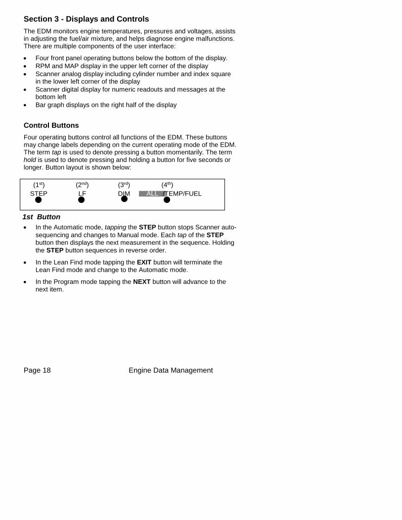
Section 3 - Displays and Controls
The EDM monitors engine temperatures, pressures and voltages, assists in adjusting the fuel/air mixture, and helps diagnose engine malfunctions. There are multiple components of the user interface:
Four front panel operating buttons below the bottom of the display.
RPM and MAP display in the upper left corner of the display
Scanner analog display including cylinder number and index square in the lower left corner of the display
Scanner digital display for numeric readouts and messages at the bottom left
Bar graph displays on the right half of the display
Control Buttons
Four operating buttons control all functions of the EDM. These buttons may change labels depending on the current operating mode of the EDM. The term tap is used to denote pressing a button momentarily. The term hold is used to denote pressing and holding a button for five seconds or longer. Button layout is shown below:
1st Button
In the Automatic mode, tapping the STEP button stops Scanner auto-
sequencing and changes to Manual mode. Each tap of the STEP button then displays the next measurement in the sequence. Holding
the STEP button sequences in reverse order.
In the Lean Find mode tapping the EXIT button will terminate the Lean Find mode and change to the Automatic mode.
In the Program mode tapping the NEXT button will advance to the next item.
STEP LF DIM
(3rd)
ALL /TEMP/FUEL
(1st) (2nd) (4th)
For Your Safe Flight ............................................. Page 19
2nd Button
In Automatic or Manual modes, tapping the LF button will activate the Lean Find mode.
In the LF mode holding the LF button after peak EGT is found will display the peak EGT.
In Automatic or Manual modes holding the LF button for three seconds will toggle between Standard and Normalize (NRM) views.
In the programming mode, tapping the PLUS or MINUS button will allow you to edit a parameter value.
Holding LF during power up will display the primary alarm limits after the self-test is complete.
1st and 2nd Buttons
Holding both the STEP and LF buttons simultaneously for five seconds will enter the pilot programming mode.
Just after entering Lean Find Mode (but before any EGT has risen), holding both First and Second buttons for five seconds will toggle between LOP or ROP leaning modes.
Tapping both the STEP and LF buttons simultaneously in Manual mode toggles to ‘include’ or ‘exclude’ the displayed non-primary measurement from the Automatic mode only. The excluded measurement will show up in the manual mode.
3rd Button
Tapping DIM (brightness decreases) or holding DIM (brightness increases)
allows decrease or increase brightness respectively.
2nd and 3rd Buttons
Holding both the LF and DIM buttons simultaneously will display the Hobbs
readings. Tap button labeled NEXT to see additional information screens.
4th Button ( ALL/TEMP/FUEL )
Select what is shown during Scanner auto-sequence. Choices are ALL,
TEMP or FUEL. Highlighted one is what is active.
Page 20 Engine Data Management
Scanner Displays
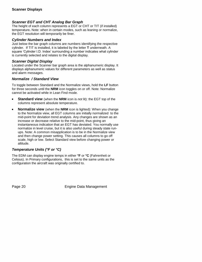
Scanner EGT and CHT Analog Bar Graph The height of each column represents a EGT or CHT or TIT (if installed)
temperature. Note: when in certain modes, such as leaning or normalize, the EGT resolution will temporarily be finer.
Cylinder Numbers and Index Just below the bar graph columns are numbers identifying the respective
cylinder. If TIT is installed, it is labeled by the letter T underneath. A square ‘Cylinder I.D. Index’ surrounding a number indicates what cylinder is currently selected and relates to the digital display.
Scanner Digital Display Located under the Scanner bar graph area is the alphanumeric display. It displays alphanumeric values for different parameters as well as status and alarm messages.
Normalize / Standard View
To toggle between Standard and the Normalize views, hold the LF button
for three seconds until the NRM icon toggles on or off. Note: Normalize cannot be activated while in Lean Find mode.
Standard view (when the NRM icon is not lit): the EGT top of the
columns represent absolute temperature.
Normalize view (when the NRM icon is lighted): When you change
to the Normalize view, all EGT columns are initially normalized to the mid-point for deviation trend analysis. Any changes are shown as an increase or decrease relative to the mid-point, thus giving an instantaneous indication that an EGT has deviated. You normally use normalize in level cruise, but it is also useful during steady state run-ups. Note: A common misapplication is to be in the Normalize view and then change power setting. This causes all columns to go off scale, high or low. Select Standard view before changing power or altitude.
Temperature Units (°F or °C)
The EDM can display engine temps in either °F or °C (Fahrenheit or Celsius). In Primary configurations, this is set to the same units as the configuration the aircraft was originally certified to.
For Your Safe Flight ............................................. Page 21
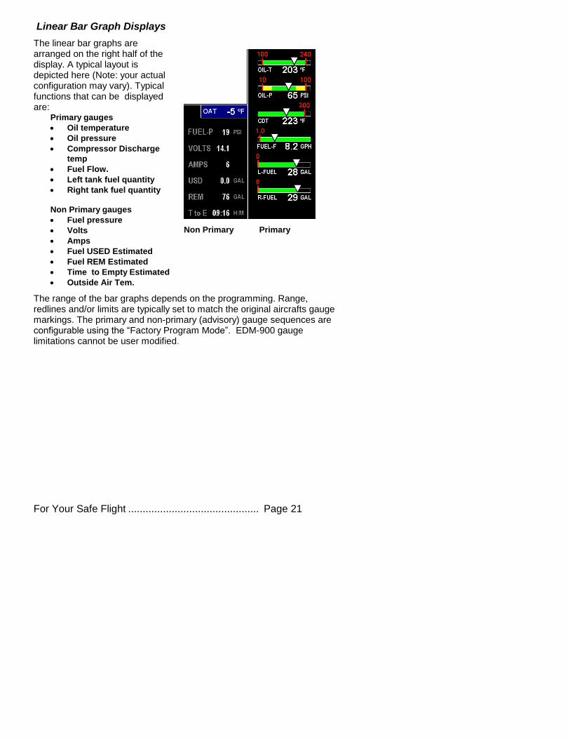
Linear Bar Graph Displays
The linear bar graphs are arranged on the right half of the display. A typical layout is depicted here (Note: your actual configuration may vary). Typical functions that can be displayed are:
Primary gauges
Oil temperature
Oil pressure
Compressor Discharge
temp
Fuel Flow.
Left tank fuel quantity
Right tank fuel quantity
Non Primary gauges
Fuel pressure
Volts
Amps
Fuel USED Estimated
Fuel REM Estimated
Time to Empty Estimated
Outside Air Tem.
The range of the bar graphs depends on the programming. Range, redlines and/or limits are typically set to match the original aircrafts gauge markings. The primary and non-primary (advisory) gauge sequences are configurable using the “Factory Program Mode”. EDM-900 gauge limitations cannot be user modified.
Non Primary Primary
Page 22 Engine Data Management
.7
Flight Duration: 02:42:21
See ‘Section 9 - First Time Setup and Customization’.
Note: Amps can operate either as a (Amps Charge) charge/discharge or (Amps Load) load meter, depending on programming.
Remote Annunciate Light
The remote auxiliary ‘ALERT LIGHT’ provides redundancy. Upon power up the Remote Annunciate Light displays Red and Yellow. If the RAL is not working abort the flight. While the EDM’s programmed configuration (aircraft make and model and primary status) is shown in the display. Mentally Confirm that it matches your aircraft configuration before using the instrument. If it does not match the aircraft configuration abort the flight.
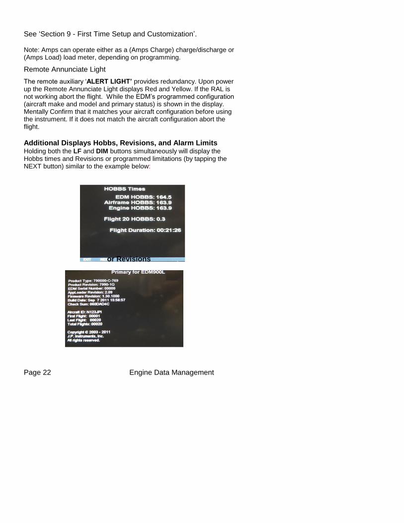
Additional Displays Hobbs, Revisions, and Alarm Limits Holding both the LF and DIM buttons simultaneously will display the Hobbs times and Revisions or programmed limitations (by tapping the NEXT button) similar to the example below:
or Revisions
REVISIONS
For Your Safe Flight ............................................. Page 23
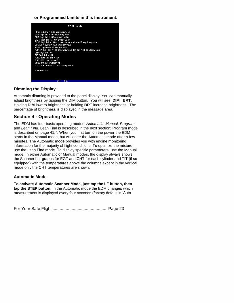
or Programmed Limits in this Instrument.
Dimming the Display
Automatic dimming is provided to the panel display. You can manually
adjust brightness by tapping the DIM button. You will see DIM BRT.
Holding DIM lowers brightness or holding BRT increase brightness. The percentage of brightness is displayed in the message area.
Section 4 - Operating Modes
The EDM has four basic operating modes: Automatic, Manual, Program and Lean Find. Lean Find is described in the next section; Program mode is described on page 41, ‘. When you first turn on the power the EDM starts in the Manual mode, but will enter the Automatic mode after a few minutes. The Automatic mode provides you with engine monitoring information for the majority of flight conditions. To optimize the mixture, use the Lean Find mode. To display specific parameters, use the Manual mode. In either Automatic or Manual modes, the display always shows the Scanner bar graphs for EGT and CHT for each cylinder and TIT (if so equipped) with the temperatures above the columns except in the vertical mode only the CHT temperatures are shown.
Automatic Mode
To activate Automatic Scanner Mode, just tap the LF button, then
tap the STEP button. In the Automatic mode the EDM changes which measurement is displayed every four seconds (factory default is ‘Auto
Page 24 Engine Data Management
Scan Rate 4’), however you can change this rate in the Program Mode. A setting of zero disables auto scanning altogether. The order of
automatic scan if the switch is in the ALL MODE: EGT/CHT, TIT, CLD, DIFF, CDT,OIL-T, REM, T to E, GPH, USD, AMP, Volts, OIL-P, and Fuel-P.
Some non-primary measurements can be excluded from the Automatic mode: tap STEP to enter the Manual mode. Tap STEP repeatedly to index to the measurement you want to exclude. Then tap both the STEP and LF buttons simultaneously. Excluded measurements display a decimal point before the measurement name. For example:
Included: 1540 CDT Excluded: 1540 ●CDT
Tapping the STEP and LF buttons simultaneously will toggle back and forth between include and exclude. Note: All measurements are always checked for alarm conditions every second.
Every time you turn on the EDM, all measurements are reset to be included.
All installed measurements are always displayed in the Manual mode. Exclusion only applies to the Automatic mode.
Manual Mode
To activate Manual Mode, just tap the STEP button. Use the Manual mode when you want to lock on one specific measurement such as shock cooling during descent, or your hottest CHT during climbs. To select the desired parameter, tap the STEP button until it appears. To return to the Automatic mode, tap the LF button and then tap the STEP button. You may completely disable the Automatic mode by setting zero for ‘Auto Scan Rate 4’. See Pilot Programming.
For Your Safe Flight ............................................. Page 25
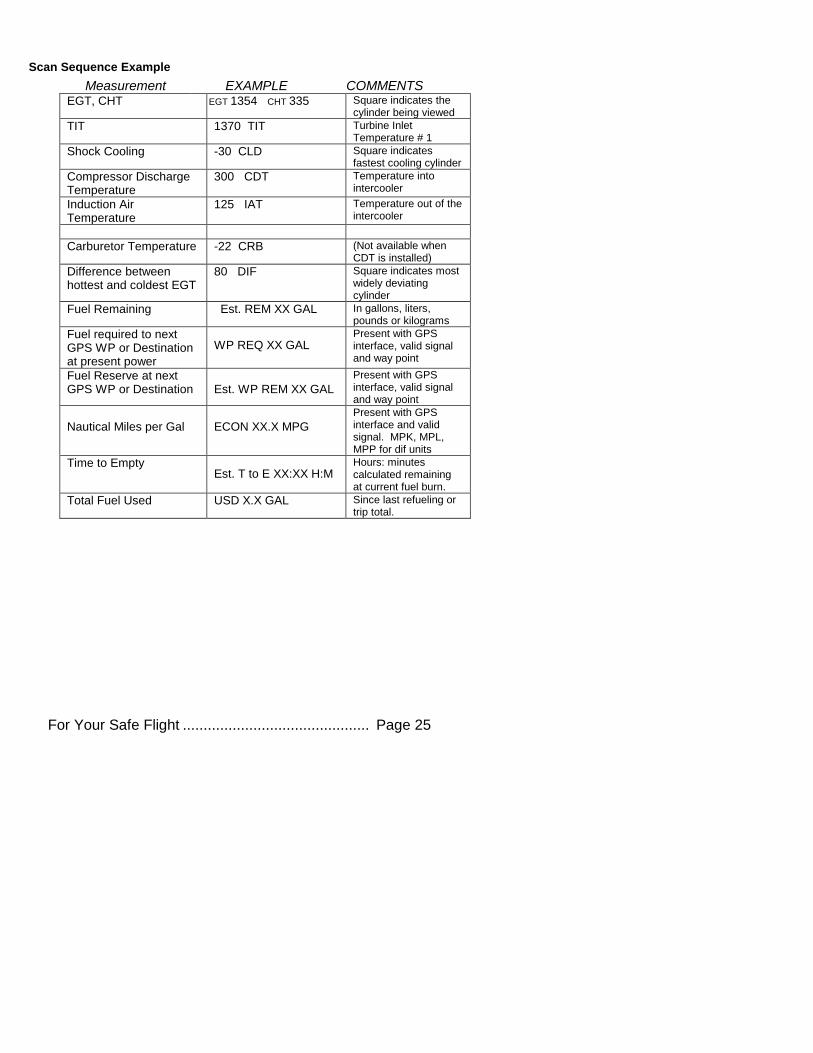
Scan Sequence Example
Measurement EXAMPLE COMMENTS EGT, CHT EGT 1354 CHT 335 Square indicates the
cylinder being viewed
TIT 1370 TIT Turbine Inlet Temperature # 1
Shock Cooling -30 CLD Square indicates fastest cooling cylinder
Compressor Discharge Temperature
300 CDT Temperature into intercooler
Induction Air Temperature
125 IAT Temperature out of the intercooler
Carburetor Temperature -22 CRB (Not available when CDT is installed)
Difference between hottest and coldest EGT
80 DIF Square indicates most widely deviating cylinder
Fuel Remaining Est. REM XX GAL In gallons, liters, pounds or kilograms
Fuel required to next GPS WP or Destination at present power
WP REQ XX GAL
Present with GPS interface, valid signal and way point
Fuel Reserve at next GPS WP or Destination
Est. WP REM XX GAL
Present with GPS interface, valid signal and way point
Nautical Miles per Gal
ECON XX.X MPG
Present with GPS interface and valid signal. MPK, MPL, MPP for dif units
Time to Empty
Est. T to E XX:XX H:M Hours: minutes calculated remaining at current fuel burn.
Total Fuel Used USD X.X GAL Since last refueling or trip total.
Page 26 Engine Data Management
Section 5 - Lean Find
The EDM supports two methods of leaning; ROP (Rich Of Peak) and
LOP (Lean Of Peak). Note: on power-up, the unit defaults to Rich Of Peak mode, but is easily changed to Lean Of Peak mode. During Rich Of Peak leaning, you’ll finalize the mixture to about 20° to 80° Rich of Peak (depending on engine operating requirements). However, with the advent of closely balanced injectors (such as GAMI), it is possible to set the mixture lean of peak—thus saving fuel and running the engine cooler. Both Rich Of Peak and Lean Of Peak processes are described in detail in this manual.
Upon reaching cruise configuration, use the Lean Find mode to identify the correct cylinder to reach peak EGT (for Rich Of Peak this is the FIRST to peak, for Lean Of Peak this is the LAST to peak). To change
from one method to the other, right after activating Lean Find, hold STEP
and LF and the other method will be momentarily shown: ROP (Rich Of
Peak) or LOP (Lean Of Peak). Release buttons after other method appears.
For Your Safe Flight ............................................. Page 27
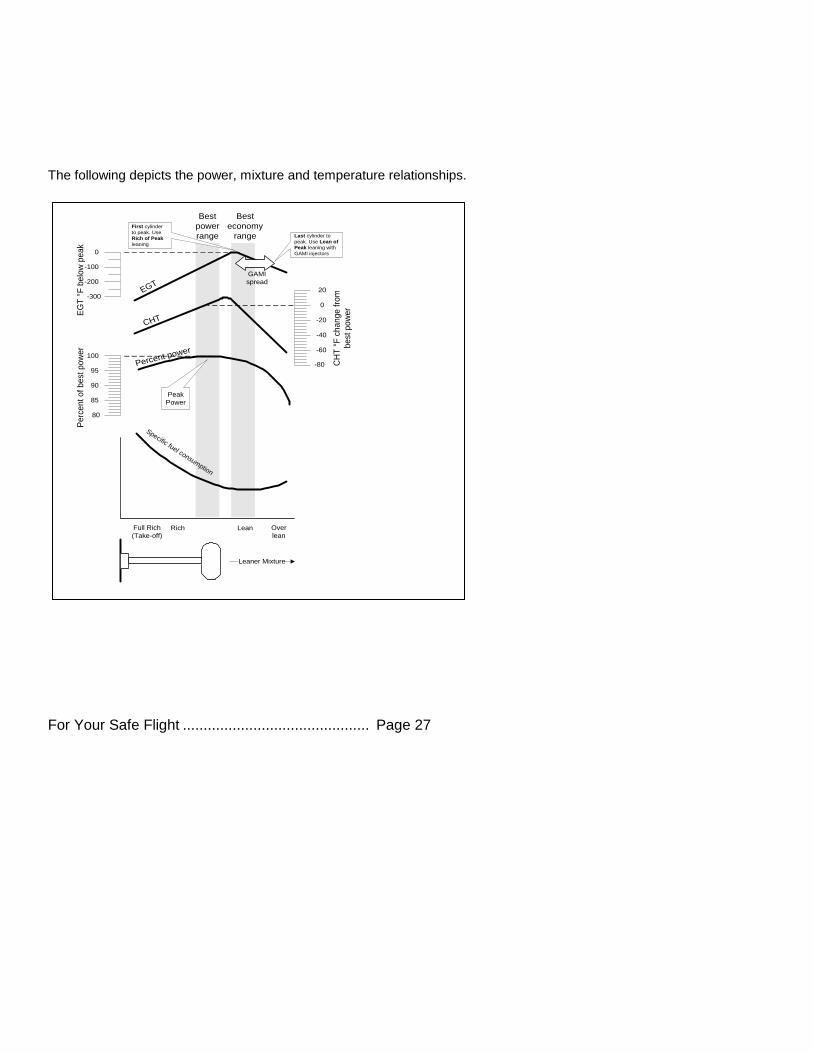
The following depicts the power, mixture and temperature relationships.
EG
T °
F b
elo
w p
ea
kP
erc
en
t o
f b
est
po
we
r
CH
T °
F c
ha
ng
e f
rom
be
st
po
we
r
Best
economy
range
Best
power
range
0
-200
-100
-300
-20
20
-60
-40
0
-80
100
85
90
95
80
EGT
CHT
Percent power
Specific fuel consumption
Over
leanLeanRichFull Rich
(Take-off)
Leaner Mixture
Peak
Power
First cylinder
to peak. Use
Rich of Peak
leaning
Last cylinder to
peak. Use Lean of
Peak leaning with
GAMI injectors
GAMI
spread
Page 28 Engine Data Management
The following pages provide step by step guidelines in leaning your engine, for both rich of peak and lean of peak modes:
As the mixture is leaned, EGT rises to a peak temperature, and then drops as the mixture is further leaned. Peak power occurs at a mixture using more fuel than a mixture set to best economy. Best economy occurs closer to peak EGT than best (peak) power. Consult your engine manufacturer’s manual for your best power and best economy settings. Accurate leaning yields optimal engine temperatures. By being able to
precisely adjust the mixture, your engine can produce either the best fuel economy or maximum power, whichever you choose.
A single EGT gauge merely gives you an average of a few cylinder’s temperature: some cylinders can be too rich, while others too
lean. Variations produced by differences in fuel distribution, ignition, and compression will cause each cylinder to peak at a different temperature. In some cases the coldest cylinder will peak first. TIT will run up to 100 degrees hotter than the hottest EGT.
For Your Safe Flight ............................................. Page 29
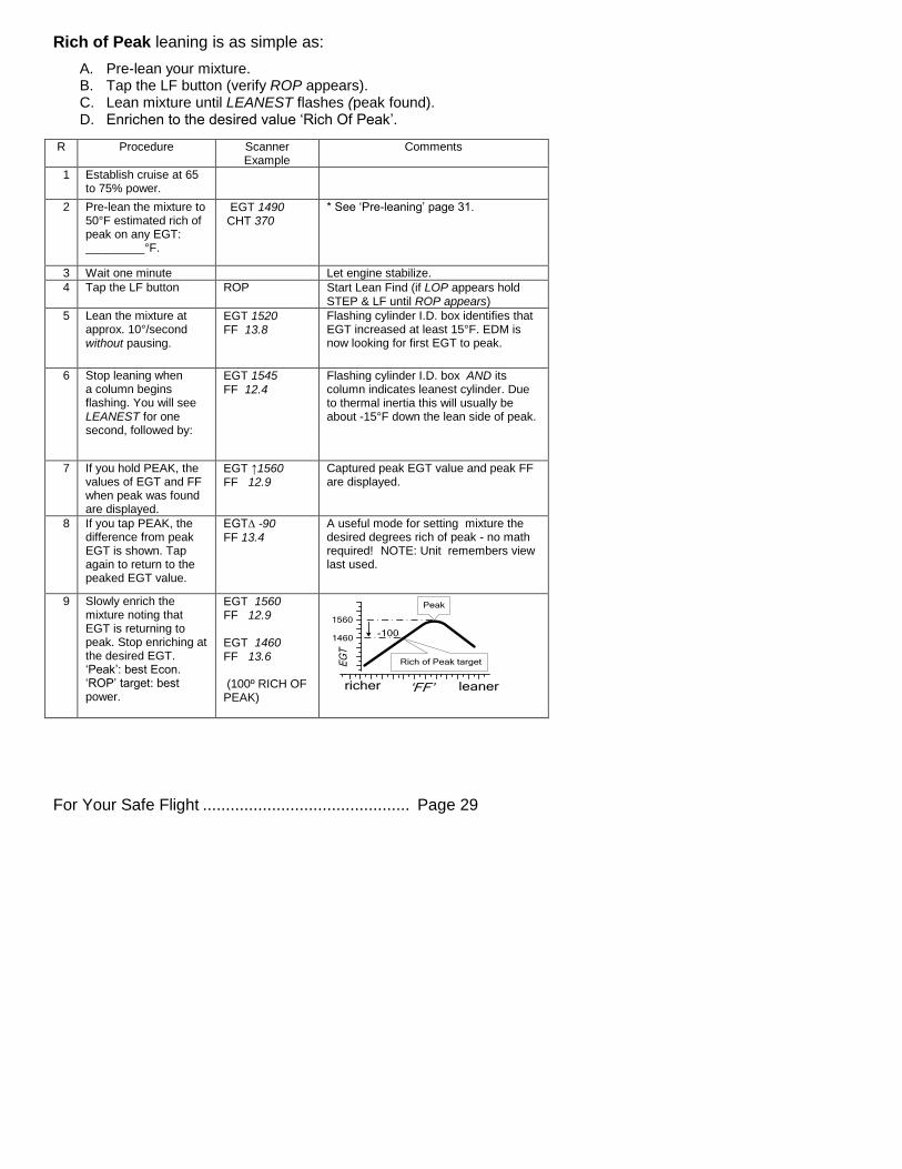
Rich of Peak leaning is as simple as:
A. Pre-lean your mixture. B. Tap the LF button (verify ROP appears). C. Lean mixture until LEANEST flashes (peak found). D. Enrichen to the desired value ‘Rich Of Peak’.
R Procedure Scanner Example
Comments
1 Establish cruise at 65 to 75% power.
2 Pre-lean the mixture to 50°F estimated rich of peak on any EGT: _________°F.
EGT 1490 CHT 370
* See ‘Pre-leaning’ page 31.
3 Wait one minute Let engine stabilize.
4 Tap the LF button ROP Start Lean Find (if LOP appears hold STEP & LF until ROP appears)
5 Lean the mixture at approx. 10°/second without pausing.
EGT 1520 FF 13.8
Flashing cylinder I.D. box identifies that EGT increased at least 15°F. EDM is now looking for first EGT to peak.
6 Stop leaning when a column begins flashing. You will see LEANEST for one second, followed by:
EGT 1545 FF 12.4
Flashing cylinder I.D. box AND its column indicates leanest cylinder. Due to thermal inertia this will usually be about -15°F down the lean side of peak.
7 If you hold PEAK, the values of EGT and FF when peak was found are displayed.
EGT ↑1560 FF 12.9
Captured peak EGT value and peak FF are displayed.
8 If you tap PEAK, the difference from peak EGT is shown. Tap again to return to the peaked EGT value.
EGT∆ -90 FF 13.4
A useful mode for setting mixture the desired degrees rich of peak - no math required! NOTE: Unit remembers view last used.
9 Slowly enrich the mixture noting that EGT is returning to peak. Stop enriching at the desired EGT. ‘Peak’: best Econ. ‘ROP’ target: best power.
EGT 1560 FF 12.9 EGT 1460 FF 13.6 (100º RICH OF PEAK)
Rich of Peak target
leanerricher ‘FF’
EG
T
1560
Peak
-1001460
Page 30 Engine Data Management
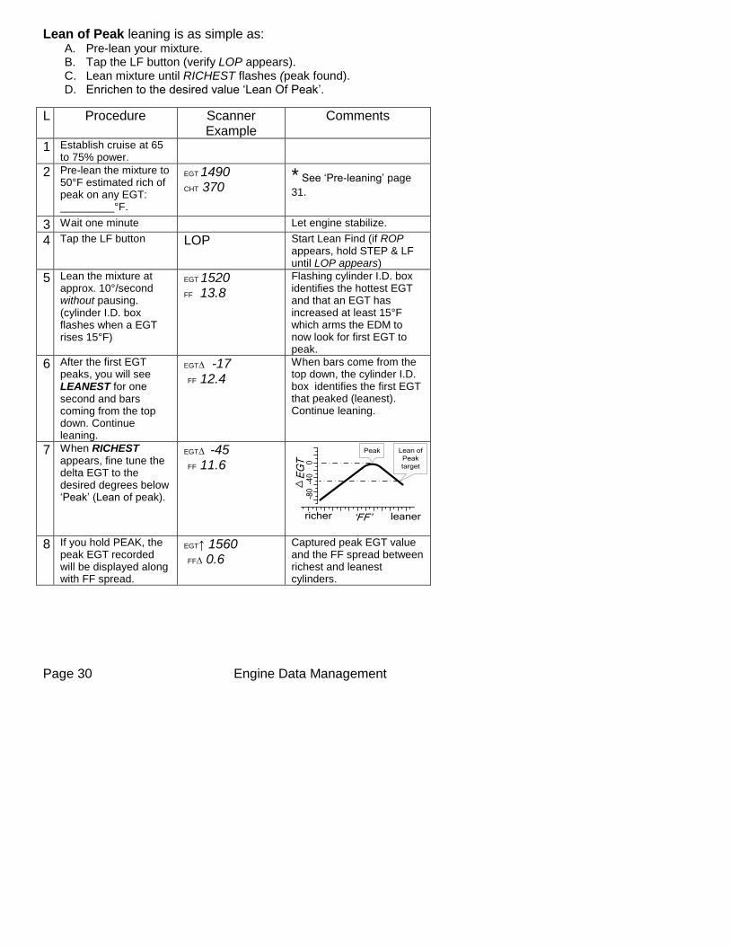
Lean of Peak leaning is as simple as: A. Pre-lean your mixture. B. Tap the LF button (verify LOP appears). C. Lean mixture until RICHEST flashes (peak found). D. Enrichen to the desired value ‘Lean Of Peak’.
L Procedure Scanner Example
Comments
1 Establish cruise at 65 to 75% power.
2 Pre-lean the mixture to 50°F estimated rich of peak on any EGT: _________°F.
EGT 1490 CHT 370
* See ‘Pre-leaning’ page
31.
3 Wait one minute Let engine stabilize.
4 Tap the LF button LOP Start Lean Find (if ROP appears, hold STEP & LF until LOP appears)
5 Lean the mixture at approx. 10°/second without pausing. (cylinder I.D. box flashes when a EGT rises 15°F)
EGT 1520
FF 13.8
Flashing cylinder I.D. box identifies the hottest EGT and that an EGT has increased at least 15°F which arms the EDM to now look for first EGT to peak.
6 After the first EGT peaks, you will see LEANEST for one second and bars coming from the top down. Continue leaning.
EGT∆ -17
FF 12.4
When bars come from the top down, the cylinder I.D. box identifies the first EGT that peaked (leanest). Continue leaning.
7 When RICHEST appears, fine tune the delta EGT to the desired degrees below ‘Peak’ (Lean of peak).
EGT∆ -45
FF 11.6
Lean of
Peak
target
leanerricher ‘FF’
EG
T 0-4
0-8
0
Peak
8 If you hold PEAK, the peak EGT recorded will be displayed along with FF spread.
EGT↑ 1560 FF∆ 0.6
Captured peak EGT value and the FF spread between richest and leanest cylinders.
For Your Safe Flight ............................................. Page 31
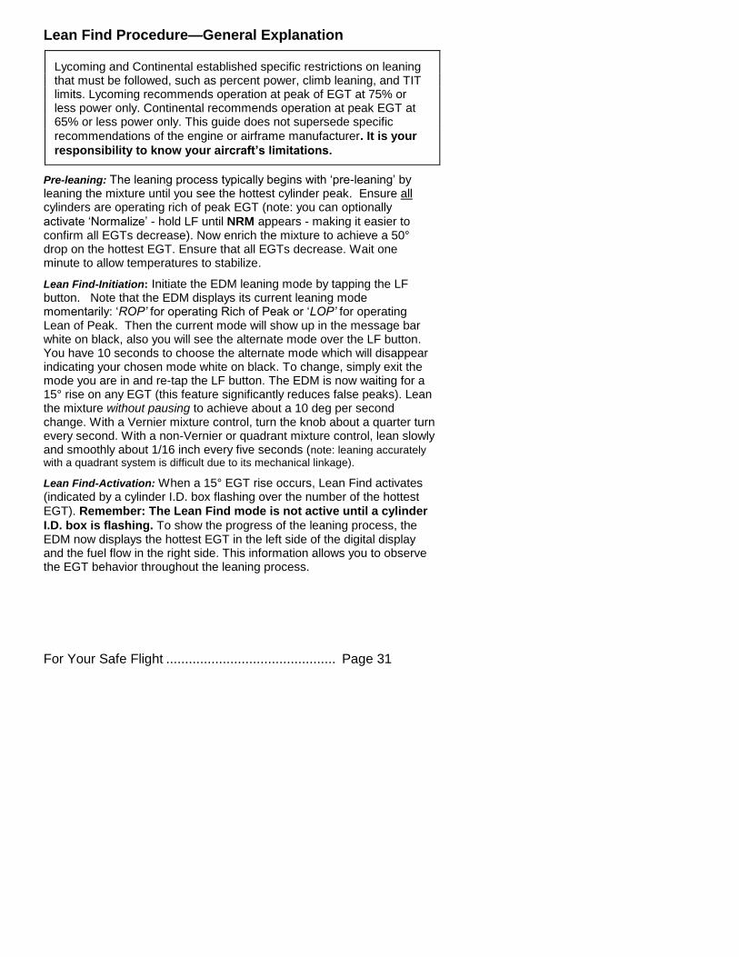
Lean Find Procedure—General Explanation
Lycoming and Continental established specific restrictions on leaning that must be followed, such as percent power, climb leaning, and TIT limits. Lycoming recommends operation at peak of EGT at 75% or less power only. Continental recommends operation at peak EGT at 65% or less power only. This guide does not supersede specific
recommendations of the engine or airframe manufacturer. It is your
responsibility to know your aircraft’s limitations.
Pre-leaning: The leaning process typically begins with ‘pre-leaning’ by leaning the mixture until you see the hottest cylinder peak. Ensure all cylinders are operating rich of peak EGT (note: you can optionally
activate ‘Normalize’ - hold LF until NRM appears - making it easier to confirm all EGTs decrease). Now enrich the mixture to achieve a 50° drop on the hottest EGT. Ensure that all EGTs decrease. Wait one minute to allow temperatures to stabilize.
Lean Find-Initiation: Initiate the EDM leaning mode by tapping the LF button. Note that the EDM displays its current leaning mode momentarily: ‘ROP’ for operating Rich of Peak or ‘LOP’ for operating Lean of Peak. Then the current mode will show up in the message bar white on black, also you will see the alternate mode over the LF button. You have 10 seconds to choose the alternate mode which will disappear indicating your chosen mode white on black. To change, simply exit the mode you are in and re-tap the LF button. The EDM is now waiting for a 15° rise on any EGT (this feature significantly reduces false peaks). Lean the mixture without pausing to achieve about a 10 deg per second change. With a Vernier mixture control, turn the knob about a quarter turn every second. With a non-Vernier or quadrant mixture control, lean slowly and smoothly about 1/16 inch every five seconds (note: leaning accurately with a quadrant system is difficult due to its mechanical linkage).
Lean Find-Activation: When a 15° EGT rise occurs, Lean Find activates (indicated by a cylinder I.D. box flashing over the number of the hottest
EGT). Remember: The Lean Find mode is not active until a cylinder
I.D. box is flashing. To show the progress of the leaning process, the EDM now displays the hottest EGT in the left side of the digital display and the fuel flow in the right side. This information allows you to observe the EGT behavior throughout the leaning process.
Page 32 Engine Data Management
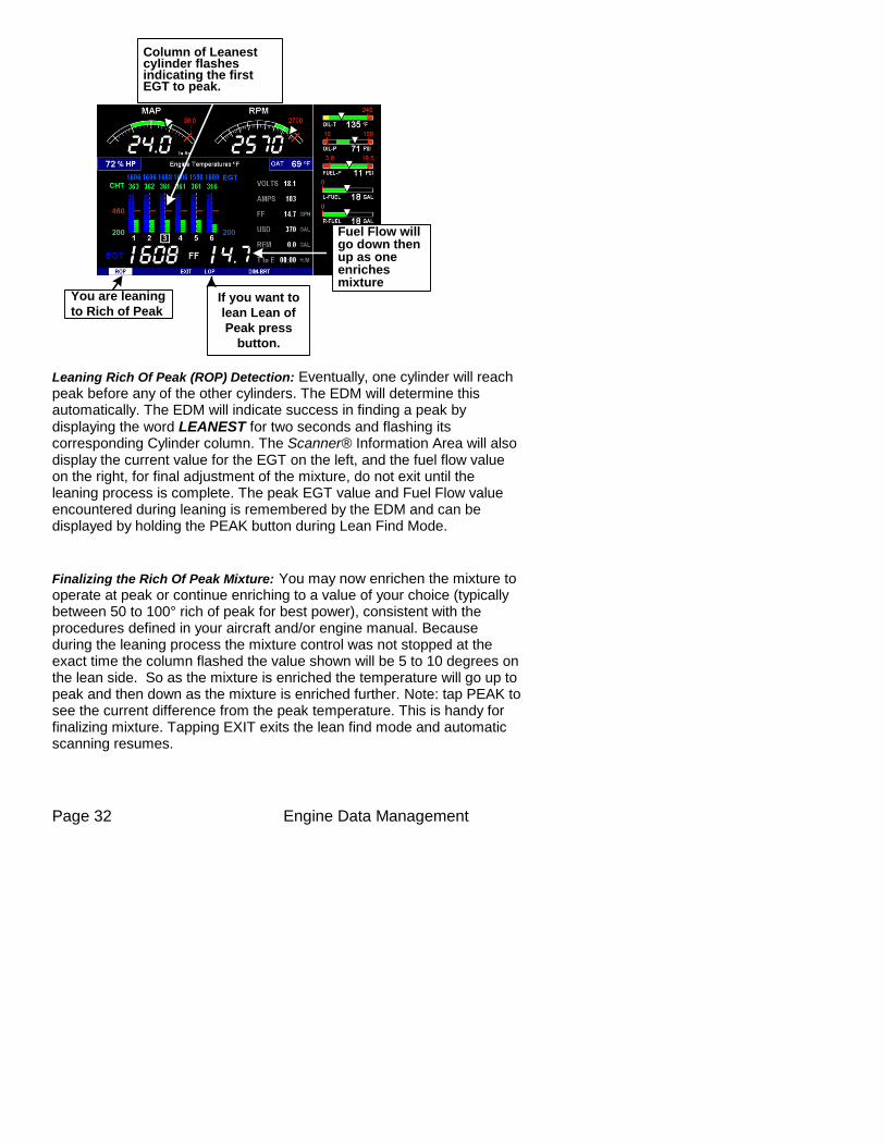
Leaning Rich Of Peak (ROP) Detection: Eventually, one cylinder will reach peak before any of the other cylinders. The EDM will determine this automatically. The EDM will indicate success in finding a peak by displaying the word LEANEST for two seconds and flashing its corresponding Cylinder column. The Scanner® Information Area will also display the current value for the EGT on the left, and the fuel flow value on the right, for final adjustment of the mixture, do not exit until the leaning process is complete. The peak EGT value and Fuel Flow value encountered during leaning is remembered by the EDM and can be displayed by holding the PEAK button during Lean Find Mode.
Finalizing the Rich Of Peak Mixture: You may now enrichen the mixture to operate at peak or continue enriching to a value of your choice (typically between 50 to 100° rich of peak for best power), consistent with the procedures defined in your aircraft and/or engine manual. Because during the leaning process the mixture control was not stopped at the exact time the column flashed the value shown will be 5 to 10 degrees on the lean side. So as the mixture is enriched the temperature will go up to peak and then down as the mixture is enriched further. Note: tap PEAK to see the current difference from the peak temperature. This is handy for finalizing mixture. Tapping EXIT exits the lean find mode and automatic scanning resumes.
Column of Leanestcylinder flashesindicating the firstEGT to peak.
You are leaning
to Rich of PeakIf you want to
lean Lean of
Peak press
button.
Fuel Flow willgo down thenup as oneenrichesmixture
For Your Safe Flight ............................................. Page 33
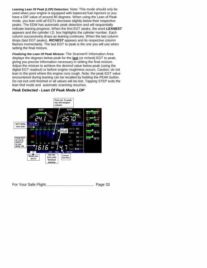
Leaning Lean Of Peak (LOP) Detection: Note: This mode should only be used when your engine is equipped with balanced fuel injectors or you have a DIF value of around 80 degrees. When using the Lean of Peak mode, you lean until all EGTs decrease slightly below their respective peaks. The EDM has automatic peak detection and will sequentially indicate leaning progress. When the first EGT peaks, the word LEANEST appears and the cylinder I.D. box highlights the cylinder number. Each column successively drops as leaning continues. When the last column drops (last EGT peaks), RICHEST appears and its respective column flashes momentarily. The last EGT to peak is the one you will use when setting the final mixture.
Finalizing the Lean Of Peak Mixture: The Scanner® Information Area
displays the degrees below peak for the last (or richest) EGT to peak, giving you precise information necessary in setting the final mixture. Adjust the mixture to achieve the desired value below peak (using the digital EGT readout) or before engine roughness occurs. Caution: do not lean to the point where the engine runs rough. Note: the peak EGT value encountered during leaning can be recalled by holding the PEAK button. Do not exit until finished or all values will be lost. Tapping STEP exits the lean find mode and automatic scanning resumes.
Peak Detected - Lean Of Peak Mode LOP
First cyl. To peak
has the longest
column
Last cyl.To peak
Peak EGTon cyl 6,Hold LFto seedelta -26
EGT Delta
over lean
Current
fuel flowMode you
are in
Do not
Exit until
finished
leaning
Page 34 Engine Data Management
Expanded Leaning Procedures
Lean Of Peak, LOP mode: During the ‘lean of peak’ process, the EDM hunts for the last cylinder to peak. Ultimately, you want to have ALL cylinders operating on the lean side of peak. You will final adjust your mixture to this cylinder. To provide a unique graphical depiction during lean of peak operation, the columns become inverted after the first EGT goes just beyond peak. Each EGT column then originates from the top of the display and drops downward. As each subsequent EGT goes past peak, its column will begin falling. The columns length depicts how far the EGT has dropped below its original peak. In this mode, each segment is
5° F. You will continue to lean until the last EGT peaks (note: never lean to the point where the engine is running rough). When the last EGT peaks, its column will flash and RICHEST appears. The digital readout will show the current temperature difference from where peak EGT occurred and the current fuel flow (if so equipped). Note: holding the PEAK button will show the captured peak value of the ‘last EGT to peak’ and also the difference in fuel flow between the first and last to peak (known as the GAMI Spread). This is a good indication of injector balance (the smaller the FF difference, the better the balance). Tapping STEP exits the lean find mode and automatic scanning resumes.
Leaning Turbocharged Engines: The leaning process for turbocharged
engines is by reference to the first EGT or TIT to reach peak. Therefore you should use the Rich Of Peak mode. The factory TIT red line (typically 1650°F to 1750°F) may limit the leaning process, depending on flight conditions. If TIT exceeds red line (but not by more than 99°), the EDM will allow you to continue leaning for one minute before a TIT alarm activates. NOTE: TIT can read approximately 100°F hotter than the hottest EGT due to unburned fuel in the exhaust igniting and is not necessarily abnormal behavior. The reduced size of the JPI Hastaloy-X-tip probes produce faster response and are more accurate than the massive factory installed probes. Therefore a JPI probe may read as much as 100°F higher than a factory installed probe.
For Your Safe Flight ............................................. Page 35
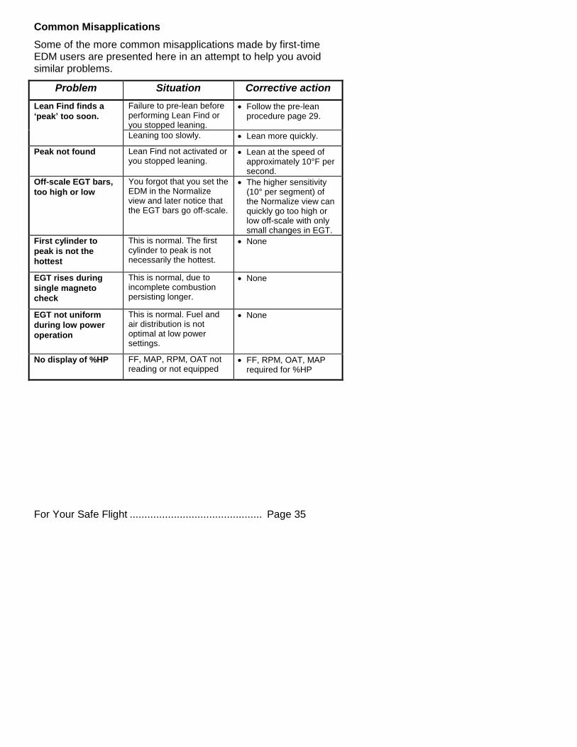
Common Misapplications
Some of the more common misapplications made by first-time EDM users are presented here in an attempt to help you avoid similar problems.
Problem Situation Corrective action
Lean Find finds a
‘peak’ too soon.
Failure to pre-lean before performing Lean Find or you stopped leaning.
Follow the pre-lean procedure page 29.
Leaning too slowly. Lean more quickly.
Peak not found Lean Find not activated or you stopped leaning.
Lean at the speed of approximately 10°F per second.
Off-scale EGT bars,
too high or low
You forgot that you set the EDM in the Normalize view and later notice that the EGT bars go off-scale.
The higher sensitivity (10° per segment) of the Normalize view can quickly go too high or low off-scale with only small changes in EGT.
First cylinder to
peak is not the
hottest
This is normal. The first cylinder to peak is not necessarily the hottest.
None
EGT rises during
single magneto
check
This is normal, due to incomplete combustion persisting longer.
None
EGT not uniform
during low power
operation
This is normal. Fuel and air distribution is not optimal at low power settings.
None
No display of %HP FF, MAP, RPM, OAT not reading or not equipped
FF, RPM, OAT, MAP required for %HP
Page 36 Engine Data Management
Section 6 - Fuel Flow Operation
Fuel Management
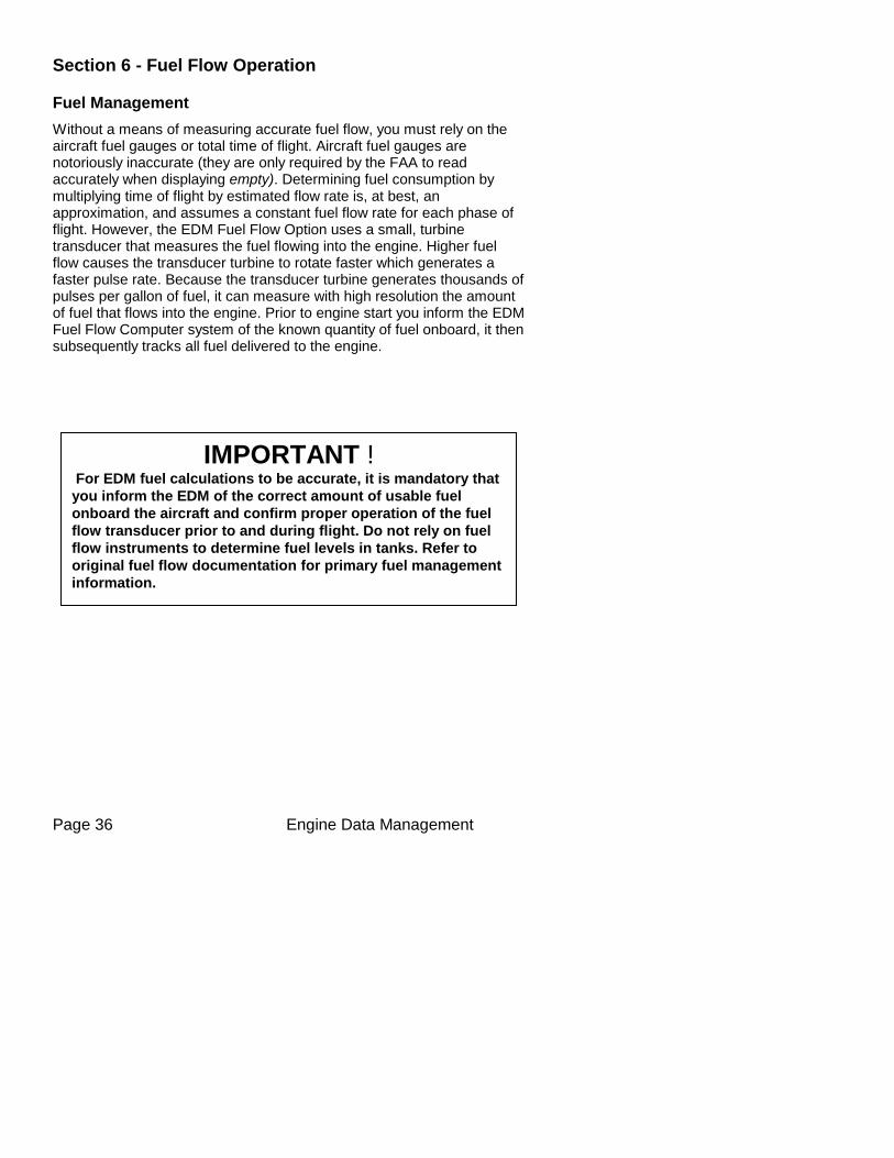
Without a means of measuring accurate fuel flow, you must rely on the aircraft fuel gauges or total time of flight. Aircraft fuel gauges are notoriously inaccurate (they are only required by the FAA to read accurately when displaying empty). Determining fuel consumption by multiplying time of flight by estimated flow rate is, at best, an approximation, and assumes a constant fuel flow rate for each phase of flight. However, the EDM Fuel Flow Option uses a small, turbine transducer that measures the fuel flowing into the engine. Higher fuel flow causes the transducer turbine to rotate faster which generates a faster pulse rate. Because the transducer turbine generates thousands of pulses per gallon of fuel, it can measure with high resolution the amount of fuel that flows into the engine. Prior to engine start you inform the EDM Fuel Flow Computer system of the known quantity of fuel onboard, it then subsequently tracks all fuel delivered to the engine.
IMPORTANT ! For EDM fuel calculations to be accurate, it is mandatory that
you inform the EDM of the correct amount of usable fuel
onboard the aircraft and confirm proper operation of the fuel
flow transducer prior to and during flight. Do not rely on fuel
flow instruments to determine fuel levels in tanks. Refer to
original fuel flow documentation for primary fuel management
information.
For Your Safe Flight ............................................. Page 37
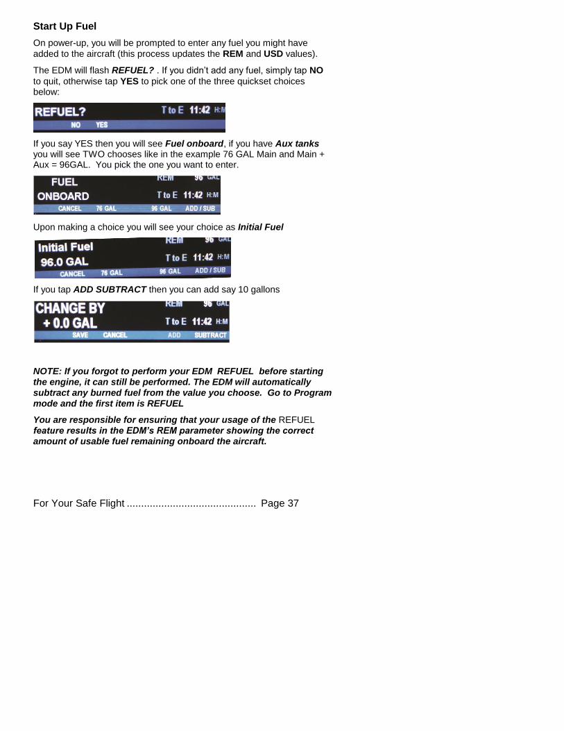
Start Up Fuel
On power-up, you will be prompted to enter any fuel you might have
added to the aircraft (this process updates the REM and USD values).
The EDM will flash REFUEL? . If you didn’t add any fuel, simply tap NO
to quit, otherwise tap YES to pick one of the three quickset choices below:
If you say YES then you will see Fuel onboard, if you have Aux tanks you will see TWO chooses like in the example 76 GAL Main and Main + Aux = 96GAL. You pick the one you want to enter.
Upon making a choice you will see your choice as Initial Fuel
If you tap ADD SUBTRACT then you can add say 10 gallons
NOTE: If you forgot to perform your EDM REFUEL before starting the engine, it can still be performed. The EDM will automatically subtract any burned fuel from the value you choose. Go to Program mode and the first item is REFUEL
You are responsible for ensuring that your usage of the REFUEL feature results in the EDM’s REM parameter showing the correct amount of usable fuel remaining onboard the aircraft.
Page 38 Engine Data Management
Resetting ‘USD’
USD is automatically reset whenever you perform REFUEL on your EDM (except if TRIP mode = yes).
After filling your tanks and prior to engine start you should inform the EDM that the aircraft has been filled. In this case USD is automatically set to zero.
To manually zero the amount of fuel USD at any time, manually STEP
to display USD and then hold both DIM (button 3) and EGT/FF (button 4) until the display shows ‘USD 0.0 GAL ’ (this normally takes about five seconds).
Trip Mode (Accumulate Trip Totalizer)
Trip mode is typically used if you want to track the total fuel used over a multi-stop cross country. To have the USD parameter continuously accumulate total consumed fuel, set TRIP? Y. ‘Trip Mode’ is described in
the ‘Program Mode section’. Note: typically, TRIP? is set to ‘N’ so that
USD will be reset every time you fuel the aircraft.
Scanner Fuel Flow Display Select
Button four selects three different Scanner filters - ALL, EGT or Fuel. Tapping this button will select the next choice (shown after the ‘/’ symbol):
ALL/TEMP: all installed parameters are shown in Scanner (and battery voltage).
TEMP/Fuel: only the installed temperature parameters are shown in Scanner.
Fuel/ALL: only fuel flow parameters are shown in Scanner.
For Your Safe Flight ............................................. Page 39
Section 7 - Alarms
Whenever a primary measured parameter falls outside of the normal allowed operating limits, i.e. goes beyond redline, the main display will blink an alert icon. This consists of the current digital value and a flashing red label in the Scanner area and the RED Remote Annunciator Light. For example, if CHT 2 is at 480, and redline is 460, the alert would be displayed as CHT2 480 oF.
Tapping the CLEAR button extinguishes the alert.
Primary alarm limits for each specific aircraft model are set by JPI in accordance with the POH and are not programmable by the pilot.
These typically include some or all of the following measurements: CHT, CDT, Oil-T, Oil-P, Fuel-P, GAL LEFT, GAL RIGHT, MAP, RPM, Fuel Flow, and TIT. To view the alarm limits screen hold both buttons 2 & 3 during normal operation, tap NEXT until the list is displayed.
The primary functions for your installation are shown on the Primary label on the back of the instrument and are identical to those specified in the FAA Approved Airplane Flight Manual/Pilot’s Operating Handbook.
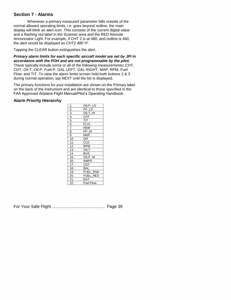
Alarm Priority Hierarchy
1. OILP_LO
2. FP_LO
3. OILT_HI
4. CHT
5. TIT
6. FLVL
7. REM
8. FP_HI
9. MAP
10. DIF
11. CLD
12. RPM
13. OILT
14. BUS
15. OILP_HI
16. AMPS
17. CDT
18. BAL
19. FUEL_END
20. FUEL_RES
21. EGT
22. Fuel Flow
Page 40 Engine Data Management
Section 8 - Memory and Data Download
The EDM compresses and records all displayed parameters once every
six seconds (default) in Long Term Data Memory (note: you can change this rate to be 1 to 500 seconds). This data is retrievable by inserting a USB Drive into the jack on the front of the instrument and following the prompts. You can choose to retrieve ‘ALL’ the data stored in the EDM, or only the ‘NEW’ data recorded since your last retrieval. In either case, the selected data in the EDM is not erased. The data can later be viewed on EZTrends2, a PC program available from JPI or over the internet.
RPM is greater than 500. The amount of data that the EDM can store will vary depending on how rapidly parameters change. The typical storage capacity is greater than 300 hours at a 6 second recording interval, but can vary depending on configuration. When the memory becomes full, the oldest data will be discarded to make room for the newest. All data are time-stamped. The EDM contains a real-time clock that may be set when you initially program your instrument. You may change the recording interval from 1 to 500 seconds, even in flight (when you change the interval in flight, the current flight file is closed and a new flight file is started at the new interval).
Downloading Data from the EDM
Downloading is a simple process. Follow the steps below: a. With the EDM powered up, plug the USB flash drive adaptor and
flash drive into the EDM USB port.
b. Wait for the EDM display to show DOWNLOAD: NEW.
c. To download only the new data since the last download, tap the STEP button.
d. To download all data in the EDM, tap the CHANGE button to see DOWNLOAD: ALL, then tap STEP.
e. You will see a ‘progress indicator’ as the data is copied to the USB flash drive. DO NOT INTERRUPT THIS PROCESS. When the download is complete the display on the EDM will show DONE and then return to normal operation.
f. Wait until the process is complete then remove the USB flash drive from the USB connector.
For Your Safe Flight ............................................. Page 41
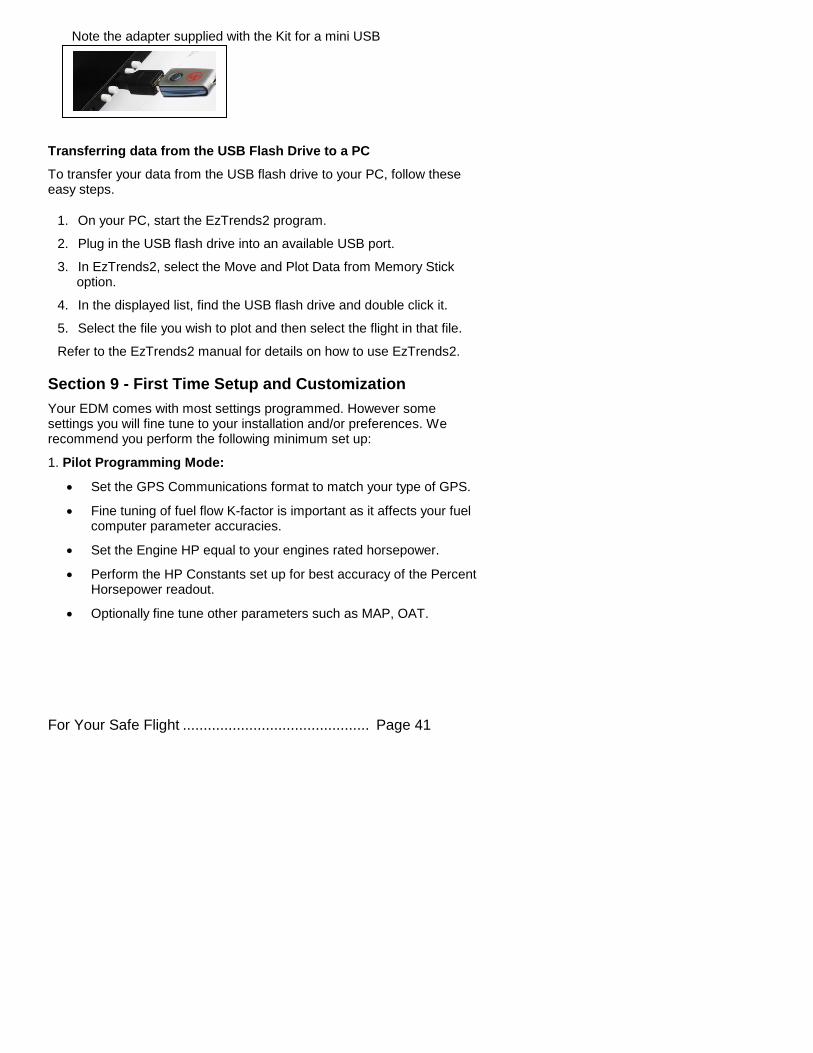
Note the adapter supplied with the Kit for a mini USB
Transferring data from the USB Flash Drive to a PC
To transfer your data from the USB flash drive to your PC, follow these easy steps.
1. On your PC, start the EzTrends2 program.
2. Plug in the USB flash drive into an available USB port.
3. In EzTrends2, select the Move and Plot Data from Memory Stick option.
4. In the displayed list, find the USB flash drive and double click it.
5. Select the file you wish to plot and then select the flight in that file.
Refer to the EzTrends2 manual for details on how to use EzTrends2.
Section 9 - First Time Setup and Customization
Your EDM comes with most settings programmed. However some settings you will fine tune to your installation and/or preferences. We recommend you perform the following minimum set up:
1. Pilot Programming Mode:
Set the GPS Communications format to match your type of GPS.
Fine tuning of fuel flow K-factor is important as it affects your fuel computer parameter accuracies.
Set the Engine HP equal to your engines rated horsepower.
Perform the HP Constants set up for best accuracy of the Percent Horsepower readout.
Optionally fine tune other parameters such as MAP, OAT.
Page 42 Engine Data Management
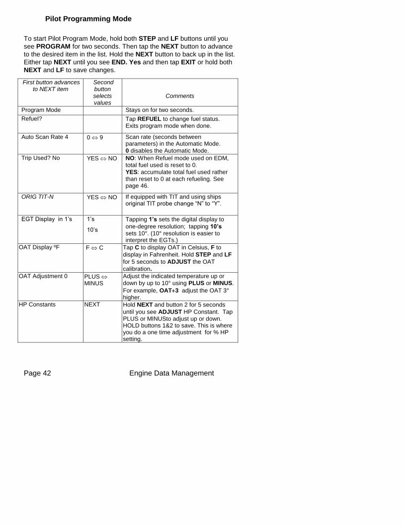
Pilot Programming Mode
To start Pilot Program Mode, hold both STEP and LF buttons until you
see PROGRAM for two seconds. Then tap the NEXT button to advance
to the desired item in the list. Hold the NEXT button to back up in the list.
Either tap NEXT until you see END. Yes and then tap EXIT or hold both
NEXT and LF to save changes.
First button advances to NEXT item
Second button selects values
Comments
Program Mode Stays on for two seconds.
Refuel? Tap REFUEL to change fuel status. Exits program mode when done.
Auto Scan Rate 4 0 9 Scan rate (seconds between parameters) in the Automatic Mode.
0 disables the Automatic Mode.
Trip Used? No
YES NO NO: When Refuel mode used on EDM, total fuel used is reset to 0.
YES: accumulate total fuel used rather than reset to 0 at each refueling. See page 46.
ORIG TIT-N YES NO If equipped with TIT and using ships original TIT probe change “N” to “Y”.
EGT Display in 1’s 1’s
10’s
Tapping 1’s sets the digital display to
one-degree resolution; tapping 10’s sets 10°. (10° resolution is easier to interpret the EGTs.)
OAT Display ºF F C Tap C to display OAT in Celsius, F to
display in Fahrenheit. Hold STEP and LF
for 5 seconds to ADJUST the OAT
calibration.
OAT Adjustment 0 PLUS MINUS
Adjust the indicated temperature up or
down by up to 10° using PLUS or MINUS.
For example, OAT3 adjust the OAT 3° higher.
HP Constants NEXT Hold NEXT and button 2 for 5 seconds
until you see ADJUST HP Constant. Tap PLUS or MINUSto adjust up or down. HOLD buttons 1&2 to save. This is where you do a one time adjustment for % HP setting.
For Your Safe Flight ............................................. Page 43
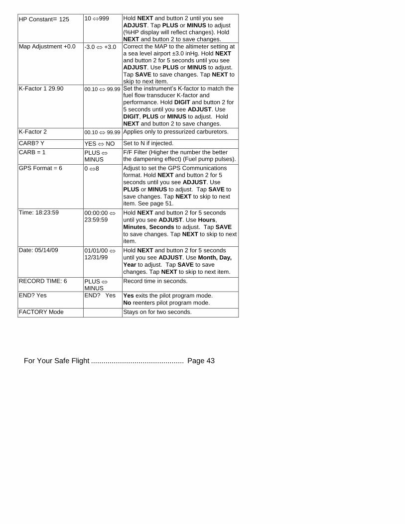
HP Constant= 125 10 999 Hold NEXT and button 2 until you see
ADJUST. Tap PLUS or MINUS to adjust (%HP display will reflect changes). Hold
NEXT and button 2 to save changes.
Map Adjustment +0.0 -3.0 +3.0 Correct the MAP to the altimeter setting at
a sea level airport ±3.0 inHg. Hold NEXT and button 2 for 5 seconds until you see
ADJUST. Use PLUS or MINUS to adjust.
Tap SAVE to save changes. Tap NEXT to skip to next item.
K-Factor 1 29.90 00.10 99.99 Set the instrument’s K-factor to match the fuel flow transducer K-factor and
performance. Hold DIGIT and button 2 for
5 seconds until you see ADJUST. Use
DIGIT, PLUS or MINUS to adjust. Hold
NEXT and button 2 to save changes.
K-Factor 2 00.10 99.99 Applies only to pressurized carburetors.
CARB? Y YES NO Set to N if injected.
CARB = 1 PLUS MINUS
F/F Filter (Higher the number the better the dampening effect) (Fuel pump pulses).
GPS Format = 6 0 8 Adjust to set the GPS Communications
format. Hold NEXT and button 2 for 5
seconds until you see ADJUST. Use
PLUS or MINUS to adjust. Tap SAVE to
save changes. Tap NEXT to skip to next item. See page 51.
Time: 18:23:59 00:00:00 23:59:59
Hold NEXT and button 2 for 5 seconds
until you see ADJUST. Use Hours,
Minutes, Seconds to adjust. Tap SAVE
to save changes. Tap NEXT to skip to next item.
Date: 05/14/09 01/01/00 12/31/99
Hold NEXT and button 2 for 5 seconds
until you see ADJUST. Use Month, Day,
Year to adjust. Tap SAVE to save
changes. Tap NEXT to skip to next item.
RECORD TIME: 6 PLUS MINUS
Record time in seconds.
END? Yes END? Yes Yes exits the pilot program mode.
No reenters pilot program mode.
FACTORY Mode Stays on for two seconds.
Page 44 Engine Data Management
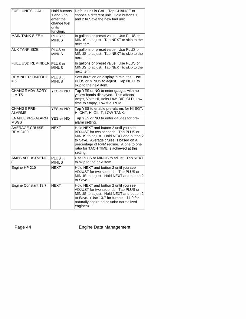
FUEL UNITS: GAL Hold buttons 1 and 2 to enter the change fuel units function.
Default unit is GAL. Tap CHANGE to choose a different unit. Hold buttons 1 and 2 to Save the new fuel unit.
MAIN TANK SIZE = PLUS MINUS
In gallons or preset value. Use PLUS or MINUS to adjust. Tap NEXT to skip to the next item.
AUX TANK SIZE = PLUS MINUS
In gallons or preset value. Use PLUS or MINUS to adjust. Tap NEXT to skip to the next item.
FUEL USD REMINDER PLUS MINUS
In gallons or preset value. Use PLUS or MINUS to adjust. Tap NEXT to skip to the next item.
REMINDER TIMEOUT = 5
PLUS MINUS
Sets duration on display in minutes. Use PLUS or MINUS to adjust. Tap NEXT to skip to the next item.
CHANGE ADVISORY LIMITS
YES NO Tap YES or NO to enter gauges with no yellow bands displayed. This affects Amps, Volts Hi, Volts Low, DIF, CLD, Low time to empty, Low fuel REM.
CHANGE PRE-ALARMS
YES NO Tap YES to enable pre-alarms for HI EGT, HI CHT, HI OIL-T, LOW TANK.
ENABLE PRE-ALARM MSGS
YES NO Tap YES or NO to enter gauges for pre-alarm setting.
AVERAGE CRUISE RPM 2400
NEXT Hold NEXT and button 2 until you see ADJUST for two seconds. Tap PLUS or MINUS to adjust. Hold NEXT and button 2 to Save. Average cruise is based on a percentage of RPM redline. A one to one ratio for TACH TIME is achieved at this setting.
AMPS ADJUSTMENT + 0
PLUS MINUS
Use PLUS or MINUS to adjust. Tap NEXT to skip to the next item.
Engine HP 210 NEXT Hold NEXT and button 2 until you see ADJUST for two seconds. Tap PLUS or MINUS to adjust. Hold NEXT and button 2 to Save.
Engine Constant 13.7 NEXT Hold NEXT and button 2 until you see ADJUST for two seconds. Tap PLUS or MINUS to adjust. Hold NEXT and button 2 to Save. (Use 13.7 for turbo’d , 14.9 for naturally aspirated or turbo normalized engines).
For Your Safe Flight ............................................. Page 45
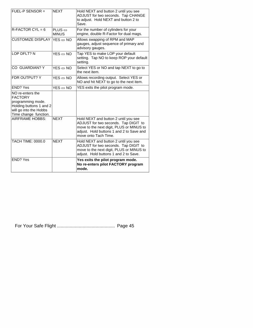
FUEL-P SENSOR = NEXT Hold NEXT and button 2 until you see ADJUST for two seconds. Tap CHANGE to adjust. Hold NEXT and button 2 to Save.
R-FACTOR CYL = 6 PLUS MINUS
For the number of cylinders for your engine, double R-Factor for dual mags.
CUSTOMIZE DISPLAY YES NO Allows swapping of RPM and MAP gauges, adjust sequence of primary and advisory gauges.
LOP DFLT? N YES NO Tap YES to make LOP your default setting. Tap NO to keep ROP your default setting.
CO GUARDIAN? Y YES NO Select YES or NO and tap NEXT to go to the next item.
FDR OUTPUT? Y YES NO Allows recording output. Select YES or NO and hit NEXT to go to the next item.
END? Yes YES NO YES exits the pilot program mode.
NO re-enters the FACTORY programming mode. Holding buttons 1 and 2 will go into the Hobbs Time change function.
AIRFRAME HOBBS: NEXT Hold NEXT and button 2 until you see ADJUST for two seconds. Tap DIGIT to move to the next digit, PLUS or MINUS to adjust. Hold buttons 1 and 2 to Save and move onto Tach Time.
TACH TIME: 0000.0 NEXT Hold NEXT and button 2 until you see ADJUST for two seconds. Tap DIGIT to move to the next digit, PLUS or MINUS to adjust. Hold buttons 1 and 2 to Save.
END? Yes Yes exits the pilot program mode.
No re-enters pilot FACTORY program
mode.
Page 46 Engine Data Management
Section 10 - Adjusting Manifold Pressure & %HP
Adjusting the HP Constant for Rich of Peak Operation
To fine tune the %HP readout, follow this procedure airborne between 5,000 and 8,000 feet MSL. (note: Verify that the MAP adjustment has been perform prior to this process).
1. Enter the pilot program mode by simultaneously holding the STEP and LF buttons for five seconds.
2. Tap STEP repeatedly until you see HP Constant. Hold both NEXT and Button 2 until you see PLUS and MINUS appear in status bar.
Now HP Constant 120 should appear. Hold both NEXT and Button 2
until you see ADJUST momentarily.
3. Set the MP and RPM per your POH to 70 percent power. Let conditions stabilize.
4. Adjust the HP Constant value PLUS or MINUS so that the %HP
reading on the display equals ‘70 %HP’. Note: this is the percent of maximum horsepower.
5. Hold both NEXT and Button 2 until you see SET.
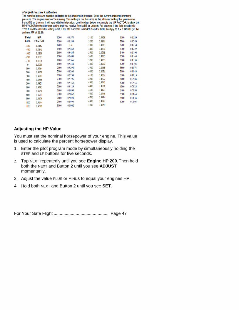
Adjusting the MAP
This procedure allows you to adjust the MAP to the altimeter setting at a
sea level airport. NOTE: If airport is not at sea level, use the
correction table on the next page to derive corrected sea level
altimeter setting).
1. Enter the pilot program mode by simultaneously holding the STEP and LF buttons for five seconds.
2. Tap NEXT repeatedly until you see MAP ADJUSTMENT +0.0. Then
hold both the NEXT and Button 2 until you see ADJUST momentarily.
3. Adjust the value using the PLUS or MINUS until the value equals the altimeter setting (sea level airport). The adjustment range for the MAP is ±3.0 inHg.
4. Hold both NEXT and Button 2 until you see SET.
For Your Safe Flight ............................................. Page 47
Adjusting the HP Value
You must set the nominal horsepower of your engine. This value is used to calculate the percent horsepower display.
1. Enter the pilot program mode by simultaneously holding the STEP and LF buttons for five seconds.
2. Tap NEXT repeatedly until you see Engine HP 200. Then hold
both the NEXT and Button 2 until you see ADJUST momentarily.
3. Adjust the value PLUS or MINUS to equal your engines HP.
4. Hold both NEXT and Button 2 until you see SET.
Page 48 Engine Data Management
Section 11 - Programming the Fuel Flow
Fuel Flow Parameters
Three additional parameters may be set by the pilot when the Fuel Flow Option is installed:
K Factor—the fuel flow transducer calibration constant.
Accumulate—default is OFF: resets the fuel used to 0 every time you inform the EDM that the aircraft was refueled. With accumulate ON, fuel used will continue to accumulate for all subsequent flights.
GPS Communications fuel data format.
K Factor
The K factor is shown on the fuel flow transducer as a four-digit number, which is the number of pulses generated per tenth gallon of fuel flow.
Before installing the transducer, write down the K factor here
_________. To enter the number into the EDM, place a decimal point two places from the right of the number. For example if the K factor written on the fuel flow transducer is ‘2912’ enter 29.12 in the EDM K factor parameter field.
The K factor can be changed in the pilot programming procedure. When the K factor is changed during a trip, calculations of fuel used, fuel remaining and time to empty are not retroactively recalculated.
Fuel Flow K factor
The K factor is shown on the fuel flow transducer as a hand written four-digit number, which represents the number of pulses per tenth gallon of
fuel flow. Before installing the transducer, record its K factor here
_________. The EDM stores the K Factor in the form 29.12, i.e. if the transducer K factor is 2912, you would enter 29.12 in the EDM’s K factor field.
Fine Tuning the K Factor
The K factor shown on the fuel flow transducer does not take into account your aircraft’s particular installation. Fuel hose diameters and lengths, elbows, fittings and routing can cause the true K factor to be different from that shown on the fuel flow transducer.
You must use the following procedure to fine tune the K factor.
For Your Safe Flight ............................................. Page 49
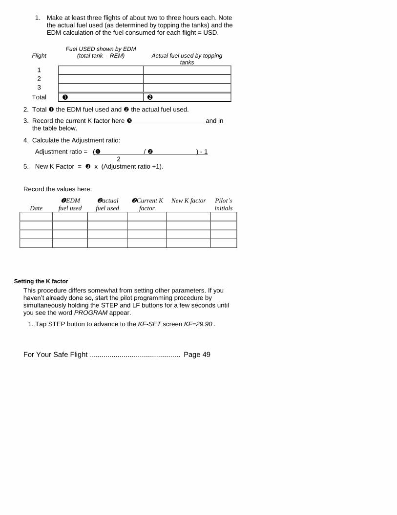
1. Make at least three flights of about two to three hours each. Note the actual fuel used (as determined by topping the tanks) and the EDM calculation of the fuel consumed for each flight = USD.
Flight
Fuel USED shown by EDM (total tank - REM)
Actual fuel used by topping
tanks
1 2 3
Total
2. Total the EDM fuel used and the actual fuel used.
3. Record the current K factor here ____________________ and in the table below.
4. Calculate the Adjustment ratio:
Adjustment ratio = ( / ) - 1 2
5. New K Factor = x (Adjustment ratio +1).
Record the values here:
Date
EDM
fuel used
actual
fuel used
Current K
factor
New K factor
Pilot’s
initials
Setting the K factor
This procedure differs somewhat from setting other parameters. If you haven’t already done so, start the pilot programming procedure by simultaneously holding the STEP and LF buttons for a few seconds until you see the word PROGRAM appear.
1. Tap STEP button to advance to the KF-SET screen KF=29.90 .
Page 50 Engine Data Management
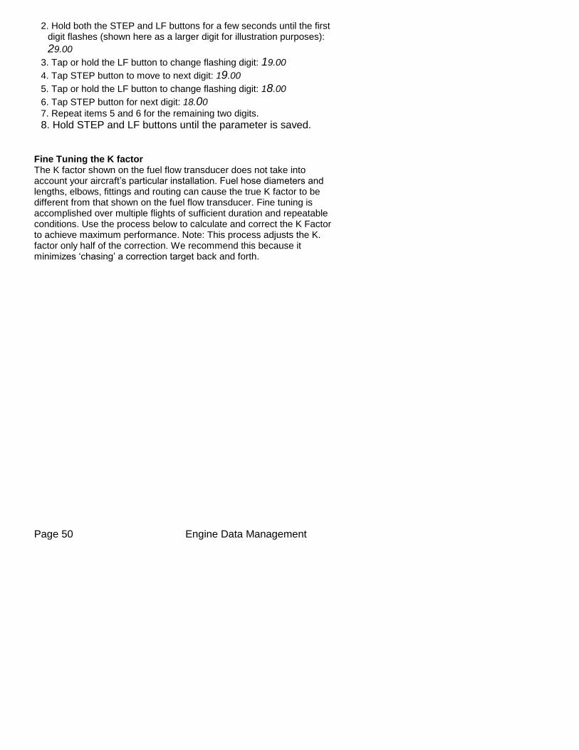
2. Hold both the STEP and LF buttons for a few seconds until the first digit flashes (shown here as a larger digit for illustration purposes):
29.00
3. Tap or hold the LF button to change flashing digit: 19.00
4. Tap STEP button to move to next digit: 19.00
5. Tap or hold the LF button to change flashing digit: 18.00
6. Tap STEP button for next digit: 18.00
7. Repeat items 5 and 6 for the remaining two digits.
8. Hold STEP and LF buttons until the parameter is saved.
Fine Tuning the K factor The K factor shown on the fuel flow transducer does not take into account your aircraft’s particular installation. Fuel hose diameters and lengths, elbows, fittings and routing can cause the true K factor to be different from that shown on the fuel flow transducer. Fine tuning is accomplished over multiple flights of sufficient duration and repeatable conditions. Use the process below to calculate and correct the K Factor to achieve maximum performance. Note: This process adjusts the K. factor only half of the correction. We recommend this because it minimizes ‘chasing’ a correction target back and forth.
For Your Safe Flight ............................................. Page 51
Programming Trip Mode
Trip Mode keeps a running total of fuel used (USD) for all flights. If Trip Mode = No, fuel ‘USD’ is zeroed after updating the EDM’s fuel computer
via Refuel modes. NOTE: to clear the fuel used display at any time, tap STEP until you see USD. Hold both DIM and ALL/EGT/FF (buttons 3&4) until the display shows ‘.0 USD’.
1. Enter the pilot program mode by simultaneously holding the STEP and LF buttons for five seconds.
2. Tap NEXT repeatedly until you see TRIP Used? No .
3. Tap YES to select the trip mode or NO to deselect mode.
4. Tap NEXT to accept your choice.
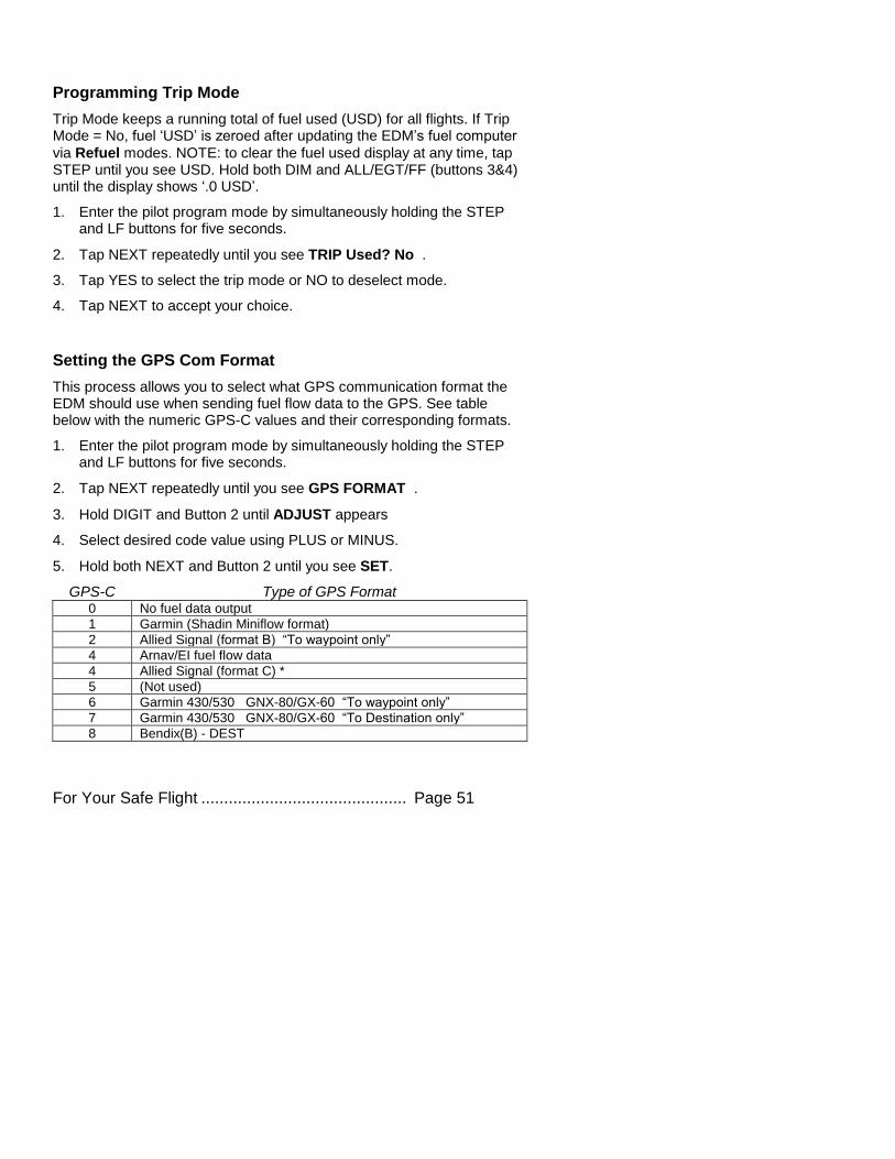
Setting the GPS Com Format
This process allows you to select what GPS communication format the EDM should use when sending fuel flow data to the GPS. See table below with the numeric GPS-C values and their corresponding formats.
1. Enter the pilot program mode by simultaneously holding the STEP and LF buttons for five seconds.
2. Tap NEXT repeatedly until you see GPS FORMAT .
3. Hold DIGIT and Button 2 until ADJUST appears
4. Select desired code value using PLUS or MINUS.
5. Hold both NEXT and Button 2 until you see SET.
GPS-C Type of GPS Format 0 No fuel data output
1 Garmin (Shadin Miniflow format)
2 Allied Signal (format B) “To waypoint only”
4 Arnav/EI fuel flow data
4 Allied Signal (format C) *
5 (Not used)
6 Garmin 430/530 GNX-80/GX-60 “To waypoint only”
7 Garmin 430/530 GNX-80/GX-60 “To Destination only”
8 Bendix(B) - DEST

Page 52 Engine Data Management
For Your Safe Flight ............................................. Page 53
Troubleshooting the EDM
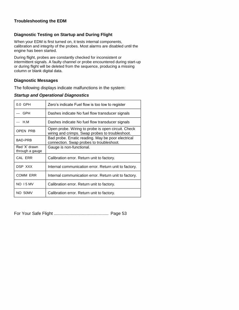
Diagnostic Testing on Startup and During Flight
When your EDM is first turned on, it tests internal components, calibration and integrity of the probes. Most alarms are disabled until the engine has been started.
During flight, probes are constantly checked for inconsistent or intermittent signals. A faulty channel or probe encountered during start-up or during flight will be deleted from the sequence, producing a missing column or blank digital data.
Diagnostic Messages
The following displays indicate malfunctions in the system:
Startup and Operational Diagnostics
0.0 GPH Zero’s indicate Fuel flow is too low to register
--- GPH Dashes indicate No fuel flow transducer signals
--- H.M Dashes indicate No fuel flow transducer signals
OPEN PRB Open probe. Wiring to probe is open circuit. Check wiring and crimps. Swap probes to troubleshoot.
BAD-PRB Bad probe. Erratic reading. May be poor electrical connection. Swap probes to troubleshoot.
Red ‘X’ drawn through a gauge
Gauge is non-functional.
CAL ERR Calibration error. Return unit to factory.
DSP XXX Internal communication error. Return unit to factory.
COMM ERR Internal communication error. Return unit to factory.
NO I 5 MV Calibration error. Return unit to factory.
NO 50MV Calibration error. Return unit to factory.
Page 54 Engine Data Management
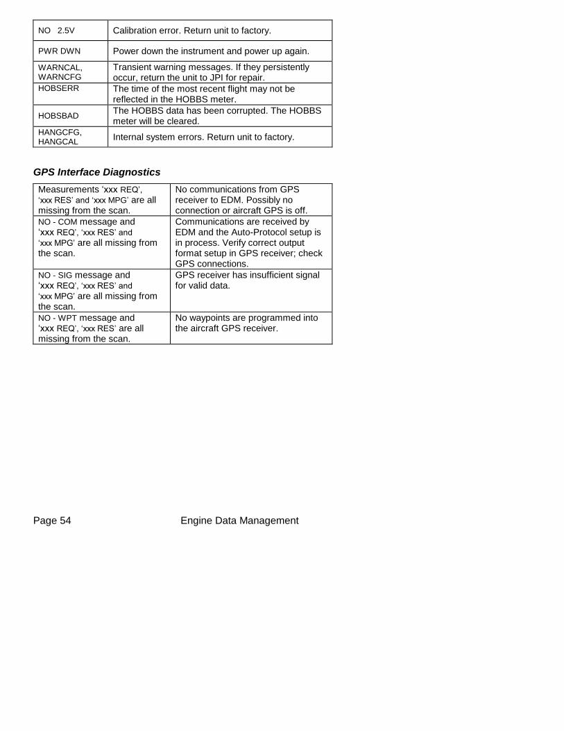
NO 2.5V Calibration error. Return unit to factory.
PWR DWN Power down the instrument and power up again.
WARNCAL, WARNCFG
Transient warning messages. If they persistently occur, return the unit to JPI for repair.
HOBSERR
The time of the most recent flight may not be reflected in the HOBBS meter.
HOBSBAD The HOBBS data has been corrupted. The HOBBS meter will be cleared.
HANGCFG, HANGCAL
Internal system errors. Return unit to factory.
GPS Interface Diagnostics
Measurements ‘xxx REQ’,
‘xxx RES’ and ‘xxx MPG’ are all missing from the scan.
No communications from GPS receiver to EDM. Possibly no connection or aircraft GPS is off.
NO - COM message and ‘xxx REQ’, ‘xxx RES’ and
‘xxx MPG’ are all missing from the scan.
Communications are received by EDM and the Auto-Protocol setup is in process. Verify correct output format setup in GPS receiver; check GPS connections.
NO - SIG message and ‘xxx REQ’, ‘xxx RES’ and
‘xxx MPG’ are all missing from the scan.
GPS receiver has insufficient signal for valid data.
NO - WPT message and ‘xxx REQ’, ‘xxx RES’ are all missing from the scan.
No waypoints are programmed into the aircraft GPS receiver.
For Your Safe Flight ............................................. Page 55
Section 12 - Appendices
Shock Cooling (CLD)
Cooling the cylinders too fast can result in cracking and eventual failure.
Lycoming Service Instruction 1094D (March 25, 1994) on Fuel Mixture
Leaning Procedures states:
“At all times, caution must be taken not to shock cool the cylinders. The maximum recommended temperature change from Lycoming should not exceed 50°F per minute cooling rate.”
JPI checks shock cooling (CLD) on all cylinders displaying the fastest cooling cylinder in degrees per minute cooling rate.
Page 56 Engine Data Management
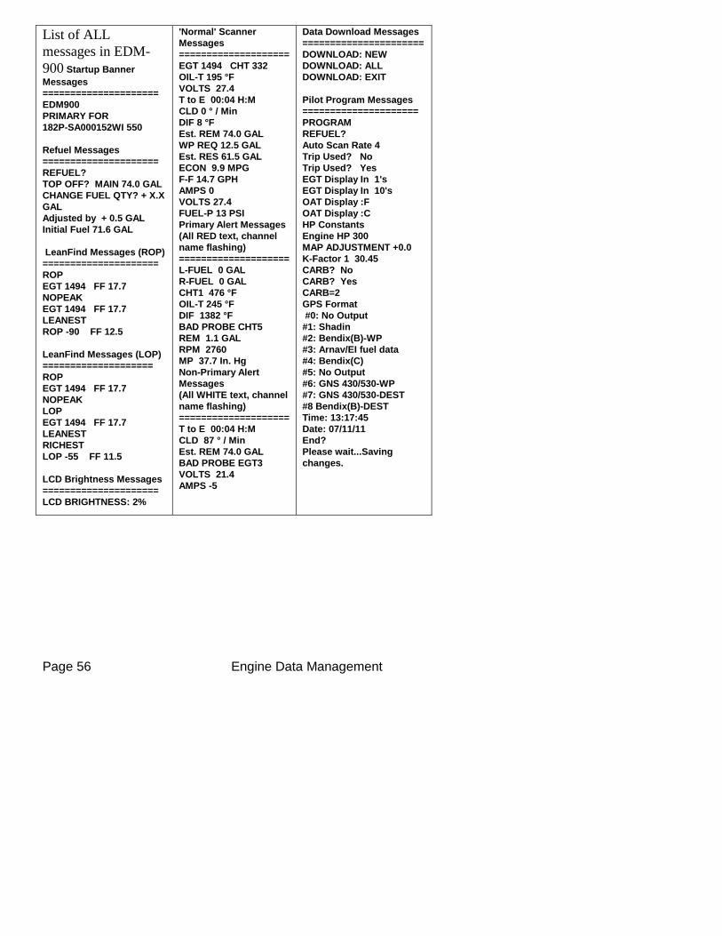
List of ALL
messages in EDM-
900 Startup Banner
Messages
=====================
EDM900
PRIMARY FOR
182P-SA000152WI 550
Refuel Messages
=====================
REFUEL?
TOP OFF? MAIN 74.0 GAL
CHANGE FUEL QTY? + X.X
GAL
Adjusted by + 0.5 GAL
Initial Fuel 71.6 GAL
LeanFind Messages (ROP)
=====================
ROP
EGT 1494 FF 17.7
NOPEAK
EGT 1494 FF 17.7
LEANEST
ROP -90 FF 12.5
LeanFind Messages (LOP)
====================
ROP
EGT 1494 FF 17.7
NOPEAK
LOP
EGT 1494 FF 17.7
LEANEST
RICHEST
LOP -55 FF 11.5
LCD Brightness Messages
=====================
LCD BRIGHTNESS: 2%
'Normal' Scanner
Messages
====================
EGT 1494 CHT 332
OIL-T 195 °F
VOLTS 27.4
T to E 00:04 H:M
CLD 0 ° / Min
DIF 8 °F
Est. REM 74.0 GAL
WP REQ 12.5 GAL
Est. RES 61.5 GAL
ECON 9.9 MPG
F-F 14.7 GPH
AMPS 0
VOLTS 27.4
FUEL-P 13 PSI
Primary Alert Messages
(All RED text, channel
name flashing)
====================
L-FUEL 0 GAL
R-FUEL 0 GAL
CHT1 476 °F
OIL-T 245 °F
DIF 1382 °F
BAD PROBE CHT5
REM 1.1 GAL
RPM 2760
MP 37.7 In. Hg
Non-Primary Alert
Messages
(All WHITE text, channel
name flashing)
====================
T to E 00:04 H:M
CLD 87 ° / Min
Est. REM 74.0 GAL
BAD PROBE EGT3
VOLTS 21.4
AMPS -5
Data Download Messages
======================
DOWNLOAD: NEW
DOWNLOAD: ALL
DOWNLOAD: EXIT
Pilot Program Messages
=====================
PROGRAM
REFUEL?
Auto Scan Rate 4
Trip Used? No
Trip Used? Yes
EGT Display In 1's
EGT Display In 10's
OAT Display :F
OAT Display :C
HP Constants
Engine HP 300
MAP ADJUSTMENT +0.0
K-Factor 1 30.45
CARB? No
CARB? Yes
CARB=2
GPS Format
#0: No Output
#1: Shadin
#2: Bendix(B)-WP
#3: Arnav/EI fuel data
#4: Bendix(C)
#5: No Output
#6: GNS 430/530-WP
#7: GNS 430/530-DEST
#8 Bendix(B)-DEST
Time: 13:17:45
Date: 07/11/11
End?
Please wait...Saving
changes.
For Your Safe Flight ............................................. Page 57
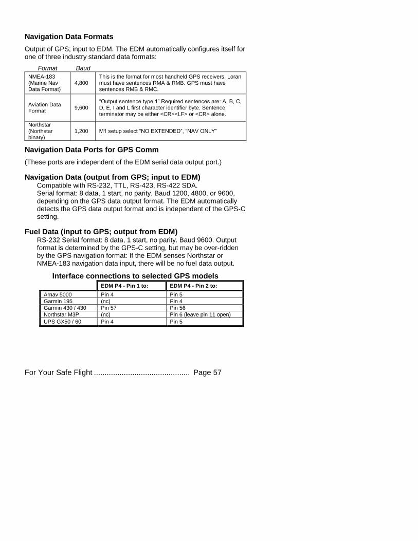
Navigation Data Formats
Output of GPS; input to EDM. The EDM automatically configures itself for one of three industry standard data formats:
Format Baud
NMEA-183 (Marine Nav Data Format)
4,800 This is the format for most handheld GPS receivers. Loran must have sentences RMA & RMB. GPS must have sentences RMB & RMC.
Aviation Data Format
9,600 “Output sentence type 1” Required sentences are: A, B, C, D, E, I and L first character identifier byte. Sentence terminator may be either <CR><LF> or <CR> alone.
Northstar (Northstar binary)
1,200 M1 setup select “NO EXTENDED”, “NAV ONLY”
Navigation Data Ports for GPS Comm
(These ports are independent of the EDM serial data output port.)
Navigation Data (output from GPS; input to EDM) Compatible with RS-232, TTL, RS-423, RS-422 SDA. Serial format: 8 data, 1 start, no parity. Baud 1200, 4800, or 9600, depending on the GPS data output format. The EDM automatically detects the GPS data output format and is independent of the GPS-C setting.
Fuel Data (input to GPS; output from EDM) RS-232 Serial format: 8 data, 1 start, no parity. Baud 9600. Output format is determined by the GPS-C setting, but may be over-ridden by the GPS navigation format: If the EDM senses Northstar or NMEA-183 navigation data input, there will be no fuel data output.
Interface connections to selected GPS models
EDM P4 - Pin 1 to: EDM P4 - Pin 2 to:
Arnav 5000 Pin 4 Pin 5
Garmin 195 (nc) Pin 4
Garmin 430 / 430 Pin 57 Pin 56
Northstar M3P (nc) Pin 6 (leave pin 11 open)
UPS GX50 / 60 Pin 4 Pin 5
Page 58 Engine Data Management
Section 13 - Technical Support
JPI offers both e-mail and telephone technical support. Have your
model and serial number ready when you call. Call JPI for a
return authorization number (RMA) before returning any equipment.
J.P.INSTRUMENTS Inc. 3185-B Airway Costa Mesa, CA 92626 Call: (800) 345-4574
Web: www.jpinstruments.com
Limited Warranty J.P. Instruments Inc. (JPI) warrants all parts in your new EDM to be free from defects in material and workmanship under normal use. Our obligation under this warranty is limited to repair or exchange of any defective part of this unit if the part is returned, shipping prepaid, within three years for electronics and one year for probes from the date of original purchase. Installation labor is the responsibility of the aircraft owner. Homebuilt aircraft warranty starts when the aircraft is certified for flight. Replacement parts carry a warranty for the balance of the warranty period.
Under this warranty, JPI is not responsible for any service charges, including removal, installation, nor any other consequential damages. JPI incurs no obligation under this warranty unless a Warranty Registration Certificate describing the warranted product has been completed and mailed to JPI with all information requested.
This warranty is void on any product which has been subject to misuse, accident, damage caused by negligence, damage in transit, handling or modification which, in the opinion of JPI, has altered or repaired the product in any way that effects the reliability or detracts from the performance of the product, or any product whereon the serial number has been altered, defaced, effaced or destroyed.
This warranty is in lieu of all other warranties expressed or implied and other obligations of liability on JPI’s part, and it neither assumes nor authorizes any other person to assume for JPI any other liability in connection with the sale of JPI products.
To initiate this warranty, the aircraft owner must submit a completed Data Logging Worksheet to JPI. Upon receiving a completed worksheet, JPI will initiate the warranty from the date of original purchase. Any replacement parts carry a warranty that extends for the balance of the period of the original warranty. For homebuilt aircraft the warranty starts when the aircraft is certificated for flight and noted on the warranty card.
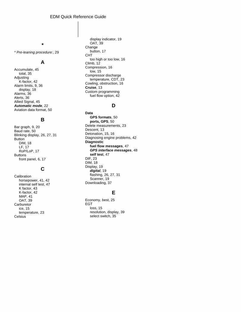
EDM Quick Reference Guide
*
* Pre-leaning procedure:, 29
A
Accumulate, 45 total, 35
Adjusting K-factor, 42
Alarm limits, 9, 36 display, 18
Alarms, 36 Alerts, 36 Allied Signal, 45 Automatic mode, 22 Aviation data format, 50
B
Bar graph, 9, 20 Baud rate, 50 Blinking display, 26, 27, 31 Button
DIM, 18 LF, 17 RoP/LoP, 17
Buttons front panel, 6, 17
C
Calibration horsepower, 41, 42 internal self test, 47 K factor, 43 K-factor, 42 MAP, 41 OAT, 39
Carburetor ice, 15 temperature, 23
Celsius
display indicator, 19 OAT, 39
Change button, 17
CHT too high or too low, 16
Climb, 12 Compression, 16
low, 15 Compressor discharge
temperature, CDT, 23 Cowling, obstruction, 16
Cruise, 13 Custom programming
fuel flow option, 42
D
Data
GPS formats, 50
ports, GPS, 50 Delete measurements, 23 Descent, 13 Detonation, 15, 16 Diagnosing engine problems, 42
Diagnostic
fuel flow messages, 47
GPS interface messages, 48
self test, 47 DIF, 23 DIM, 18 Display, 19
digital, 19 flashing, 26, 27, 31 Scanner, 19
Downloading, 37
E
Economy, best, 25 EGT
loss, 15 resolution, display, 39 select switch, 35
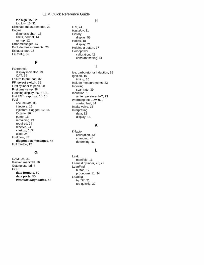
EDM Quick Reference Guide
too high, 15, 32 too low, 15, 32
Eliminate measurements, 23 Engine
diagnosis chart, 15 limits, normal, 14 run-up, 12
Error messages, 47 Exclude measurements, 23 Exhaust leak, 16 EzConfig, 39
F
Fahrenheit display indicator, 19 OAT, 39
Failure to pre-lean, 32
FF, select switch, 35 First cylinder to peak, 28 First time setup, 38 Flashing display, 26, 27, 31 Flat EGT response, 15, 16 Fuel
accumulate, 35 injectors, 16 injectors, clogged, 12, 15 Octane, 16 pump, 16 remaining, 24 required, 24 reserve, 24 start up, 6, 34 used, 24
Fuel flow, 33
diagnostics messages, 47 Full throttle, 12
G
GAMI, 24, 31 Gasket, manifold, 16 Getting started, 4 GPS
data formats, 50
data ports, 50
interface diagnostics, 48
H
H.S, 24 Hastaloy, 31 History
display, 55 Hobbs, 18
display, 21 Holding a button, 17 Horsepower
calibration, 42 constant setting, 41
I
Ice, carburetor or induction, 15 Ignition, 16
timing, 15 Include measurements, 23 Indexing
scan rate, 39 Induction, 15
air temperature, IAT, 23 Informing the EDM-930
startup fuel, 34 Intake valve, 15 Interpreting
data, 12 display, 15
K
K-factor calibration, 43 changing, 44 determing, 43
L
Leak manifold, 16
Leanest cylinder, 26, 27 LeanFind
button, 17 procedure, 11, 24
Leaning by TIT, 31 too quickly, 32
EDM Quick Reference Guide
LF. See LeanFind Long Term Memory
operation, 37
M
Manual mode, 23 MAP
calibration, 40, 41 display, 9
Miles per gallon, 24 Misapplications, 32 Missing
column, 15 Mixture, 28
best economy, 25 best power, 25
MPG, MPK, MPL, MPP, 24
N
Nautical miles per gallon, 24
Navigation data formats, 50 NMEA-183, 50 NO COM, 48 NO SIG, 48 NO WPT, 48 Normal engine limits, 14
Normalize view, 19 Northstar binary format, 50 NRM, 19
O
OAT calibration, 39 F or C, 39
Octane, 16
Off-scale EGT bars, 32 OPEN PRB, 47 Operation, 17, 22
fuel flow monitor, 33
P
Parameter indexing, 10 Peak EGT, 28 PEAK EGT, 26, 27, 29
Pilot programming fuel flow option, 42
Power, best, 25 Primary
preset alarm limits, 4 Product support, 51 Programming
fuel flow option, 42
R
RAD, 8 Range, normal temperature, 14 Rate
baud, 50 fuel flow, 33 indexing, 39 shock cooling, 13
Recording. See Long Term Memory Red line, 14 REM, 24 Remove measurements, 23 REQ, 24 RES, 24 Resolution, EGT display, 39 Rich of Peak, 24 RoP/LoP
button, 17 Rough engine, 15 RPM
display, 9 RS-232, 50 Run-up, 12
S
Scanner displays, 19
Select switch, 35 Setting the K factor. See Fuel Flow Setup, 38
fuel flow option, 42 Shadin Miniflow, 45 Shock cooling, 13, 14, 23, 49 Spark plug
fouling, 12, 15 Standard view, 19 Startup
EDM Quick Reference Guide
diagnostics, 47 fuel, 6, 34
Stuck valve, 15 Switch, select, 35
T
Tachometer. See RPM Take-off, 12 Tapping a button, 17 Technical support, 51 Test, self, 47 Time to empty, 24 Timing, ignition, 15 TIT, 31 Toggle, N, P, 19 Total
fuel used, 24, 45 Total fuel, 35 Transducer, fuel flow, 33 Trip total, 45 Troubleshooting
engine, 15 GPS, 48
Trouibleshooting fuel flow, 47
Turbocharged Engines, 31
U
Uniform, CHT, EGT not, 15 USD, 24
V
Valve lifter, 15 stuck, 15
Vapor, 16 View
change diagram, 18 normalize, Standard, 19
W
Warranty, 51