Embed Size (px)
Citation preview
Pilot’s GuideEngine Data Management
EDM-700EDM-800
EDM-711 Primary
Copyright 2000-2007 J.P. Instruments, Inc.
All Rights Reserved
J.P. INSTRUMENTS INC.
Information: P. O. Box 7033Huntington Beach, CA 92646
Factory: 3185 B AirwayCosta Mesa, CA 92626
(714) 557-5434 (800) 345 4574
Fax (714) 557-9840www.jpinstruments.com
www.jpitech.comwww.BuyJPI.com
Printed in the United States of America Rev W 3/2009Last printed 3/15/2012 01:20:00 PM
Table of Contents
Section 1 - Introduction 1Product Features 1Engine Data Management 1Benefits of Proper Mixture Control 2JPI Probes 2Temperature and Mixture 2
Section 2 - Displays and Controls 4Displays 4Modes 7Buttons 8Parameter Scan— EDM-700 without Fuel Flow Options 9Automatic Parameter Scan—EDM-711 10
Section 3 - Operating Procedures 11Diagnostic Testing on Startup and During Flight 11Modes 11Automatic Mode 11Manual Mode 12LeanFind Mode—Leaning Rich of Peak 12LeanFind Procedure—General Explanation 14Operation for each Phase of Flight 18Shock Cooling 19Common Misapplications 20
Section 4 - Diagnosing Engine Problems 21Alarms 24Pre-Ignition and Detonation 25
Section 5 - Fuel Flow Option Operation 26Fuel Flow Display Select Switch 26Fuel Management 28Parameter Scan—Systems with Fuel Flow Option 28
Section 6 - Long Term Data Memory 30Downloading from Long Term Memory 31Downloading Data from the EDM to a Flash Drive 31Downloading from USB Flash Drive to a PC 32
Section 7 - Personalizing 33Pilot Programming 33
Section 8 - Programming the EDM-800 Horsepower Constant 35Section 9 - Programming Manifold Pressure (MAP) 35Section 10 - Programming use of Factory Original TIT Probe 36Section 11 - Programming the Fuel Flow Option 38
Fuel Flow Option Programming Procedure 40Section 12 - Programming Long Term Data Memory 40Section 13 - EDM-711 Primary Alarm Display 41Section 14 - Alarm Limits 42
MAP, Fuel Flow Alarm Limits, Units, Fuel Capacity 44Navigation Data Formats 46GPS-C Fuel Flow Format for GPS Bi-directional Comm 46Diagnostic Messages, Fuel Flow 46Navigation Data Ports for GPS Comm 47
Section 15 - Option Connector Pin Assignments 48Section 16 - Reference Reading 49Section 17 - Technical Support 49 Limited Warranty 50 Index 51
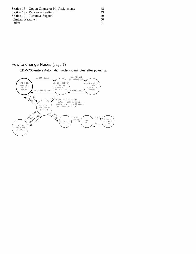
How to Change Modes (page 7)
EDM-700 enters Automatic mode two minutes after power up
A U T O I N D E Xp a r a m e t e r s
a u t o m a t i c a l l yi n d e x e d
M A N U A L I N D E Xp a r a m e t e r s
i n d e x e d w h e ns t e p i n t a p p e d
T o g g l e t o i n c l u d e /e x c l u d e
p a r a m e t e r i ni n d e x i n g
L E A N F I N Ds t a r t s L e a n F i n d
p r o c e d u r e
T o g g l e b e t w e e nL E A N R a n d
L E A N L o f p e a k
d o t f l a s h e ss e e
L E A N E S T
D i s p l a y sp e a k E G T
v a l u e
t a p S T E P b u t t o n
t a p L F , t h e n t a p S T E P
t a p S T E P a n dL F s i m u l t a n e o u s l y
r e l e a s e b u t t o n s
LFLF
STEP
hold both STEP
and LF
simulta
neouslybeginleaning c o n t i n u e
l e a n i n gh o l d L F
r e l e a s eL F
I n L e a n o f p e a k , a f t e r f i r s tL e a n F i n d , L F w i l l r e t u r n t o t h ei n v e r t e d b a r g r a p h . T a p L F a g a i n t os t a r t L e a n F i n d p r o c e d u r e
Section 1 - Introduction
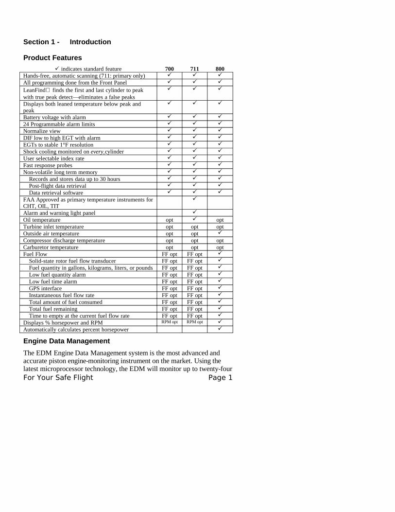
Product Features
indicates standard feature 700 711 800Hands-free, automatic scanning (711: primary only)
All programming done from the Front Panel
LeanFind finds the first and last cylinder to peak with true peak detect—eliminates a false peaks
Displays both leaned temperature below peak and peak
Battery voltage with alarm
24 Programmable alarm limits
Normalize view
DIF low to high EGT with alarm
EGTs to stable 1°F resolution
Shock cooling monitored on every cylinder
User selectable index rate
Fast response probes
Non-volatile long term memory
Records and stores data up to 30 hours
Post-flight data retrieval
Data retrieval software
FAA Approved as primary temperature instruments for CHT, OIL, TIT
Alarm and warning light panel
Oil temperature opt optTurbine inlet temperature opt opt optOutside air temperature opt opt
Compressor discharge temperature opt opt optCarburetor temperature opt opt optFuel Flow FF opt FF opt
Solid-state rotor fuel flow transducer FF opt FF opt
Fuel quantity in gallons, kilograms, liters, or pounds FF opt FF opt
Low fuel quantity alarm FF opt FF opt
Low fuel time alarm FF opt FF opt
GPS interface FF opt FF opt
Instantaneous fuel flow rate FF opt FF opt
Total amount of fuel consumed FF opt FF opt
Total fuel remaining FF opt FF opt
Time to empty at the current fuel flow rate FF opt FF opt
Displays % horsepower and RPM RPM opt RPM opt
Automatically calculates percent horsepower
Engine Data Management
The EDM Engine Data Management system is the most advanced and accurate piston engine-monitoring instrument on the market. Using the latest microprocessor technology, the EDM will monitor up to twenty-four For Your Safe Flight Page 1
critical parameters in your engine, four times a second, with a linearized thermocouple accuracy of better than 0.1 percent or 2 F°.
As your built-in flight engineer, the EDM is constantly “red line” checking: all critical parameters are automatically checked four times a second, regardless of the current display status. Leaning is accomplished quickly and automatically using the LeanFind procedure. With the EDM it is now possible to have substantially more diagnostic information available to you in a timely and usable manner.
The real-time serial data port—a standard feature—permits you to record scanned parameters in real-time using a user-supplied laptop PC.
Benefits of Proper Mixture Control
• Improved engine efficiency • Reduced maintenance costs
• Greater fuel economy • Reduced operating costs• Smoother engine operation • Proper engine
temperatures• Longer spark plug life • Reduced engine vibration
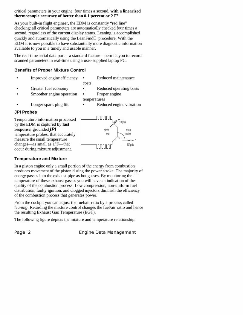
JPI Probes
Temperature information processed by the EDM is captured by fast response, grounded JPI temperature probes, that accurately measure the small temperature changes—as small as 1°F—that occur during mixture adjustment.
Temperature and Mixture
In a piston engine only a small portion of the energy from combustion produces movement of the piston during the power stroke. The majority of energy passes into the exhaust pipe as hot gasses. By monitoring the temperature of these exhaust gasses you will have an indication of the quality of the combustion process. Low compression, non-uniform fuel distribution, faulty ignition, and clogged injectors diminish the efficiency of the combustion process that generates power.
From the cockpit you can adjust the fuel/air ratio by a process called leaning. Retarding the mixture control changes the fuel/air ratio and hence the resulting Exhaust Gas Temperature (EGT).
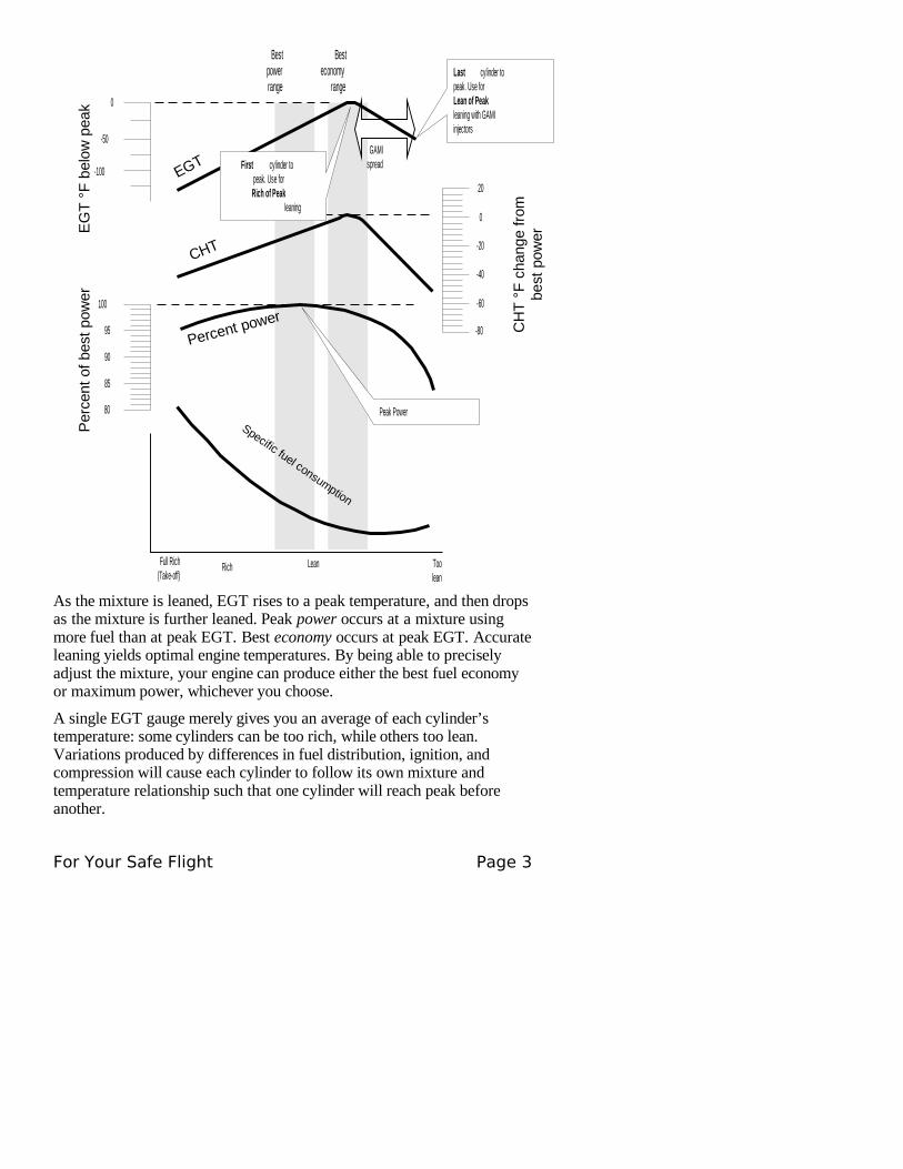
The following figure depicts the mixture and temperature relationship.
Page 2 Engine Data Management
CHT probe
EGT probe
cylinderhead
exhaustmanifold
EG
T °
F b
elow
pea
kP
erce
nt o
f be
st p
ower
CH
T °
F c
hang
e fr
ombe
st p
ower
Bestpowerrange
0
-100
-50
-20
20
-60
-40
0
-80
100
85
90
95
80
Percent power
Specific fuel consumption
Toolean
LeanRichFull Rich(Take-off)
EGT
CHT
First cylinder topeak. Use forRich of Peak
leaning
Last cylinder topeak. Use forLean of Peakleaning with GAMIinjectors
Peak Power
Besteconomy
range
GAMIspread
As the mixture is leaned, EGT rises to a peak temperature, and then drops as the mixture is further leaned. Peak power occurs at a mixture using more fuel than at peak EGT. Best economy occurs at peak EGT. Accurate leaning yields optimal engine temperatures. By being able to precisely adjust the mixture, your engine can produce either the best fuel economy or maximum power, whichever you choose.
A single EGT gauge merely gives you an average of each cylinder’s temperature: some cylinders can be too rich, while others too lean. Variations produced by differences in fuel distribution, ignition, and compression will cause each cylinder to follow its own mixture and temperature relationship such that one cylinder will reach peak before another.
For Your Safe Flight Page 3
Section 2 - Displays and Controls
The EDM monitors engine temperatures and voltages, assists in adjusting the fuel/air mixture, and helps diagnose engine malfunctions. There are three components of the user interface:
• Analog display including cylinder number and index dot• Digital display for numeric readouts and messages• Two front panel operating buttons.
Displays
I 3 4 0 3 7 6S T E P L F
1 2 3 4 5 6 T7 3 H P
N R M F
E D M 8 0 0J P I
_E G T
%L i m i t
_2 5 0
3 5 0
4 5 0C H T
T S O
° F o r ° C
D a s h l i n e o rN R M i n d i c a t e s
N o r m a l i z e o rP e r c e n t v i e w
C y l i n d e rn u m b e r s 1
t h r o u g h 6 . T i sT I T o t h e r w i s e
o i l t e m p
E x h a u s t G a sT e m p e r a t u r e( E G T ) i s t h e t o p o ft h e c o l u m n
P e r c e n tH P
o r R P M( E D M -
8 0 0 o n l y )
D o t i n d i c a t e s w h i c hc y l i n d e r t e m p e r a t u r e s
a r e s h o w n i n t h ed i g i t a l d i s p l a y
C y l i n d e r H e a dT e m p e r a t u r e
( C H T ) i s s h o w na s a m i s s i n g
s e g m e n t
M a x i m u ml i n e i s t h eE G T , T I T
a n d O I Lr e d l i n e
C H Ta b s o l u t e
s c a l e
S y s t e m s w i t hb o t h T I T a n dO I L , O I L i ss h o w n a sm i s s i n g s e g m e n t
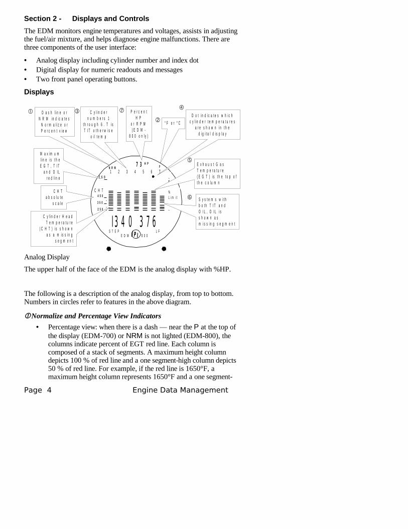
Analog Display
The upper half of the face of the EDM is the analog display with %HP.
The following is a description of the analog display, from top to bottom. Numbers in circles refer to features in the above diagram.
Normalize and Percentage View Indicators
• Percentage view: when there is a dash — near the P at the top of the display (EDM-700) or NRM is not lighted (EDM-800), the columns indicate percent of EGT red line. Each column is composed of a stack of segments. A maximum height column depicts 100 % of red line and a one segment-high column depicts 50 % of red line. For example, if the red line is 1650°F, a maximum height column represents 1650°F and a one segment-
Page 4 Engine Data Management
high column represents half that value, or 825°F. The Percentage view permits comparison of EGTs across all cylinders. Hotter cylinders display higher columns than cooler cylinders.
• Normalize view: when there is a dash _ near the N at the top of the display (EDM-700) or the letters NRM are lighted on the left side (EDM-800), the EGT columns are displayed normalized. When you change to the Normalize view, all column peaks are set to the same half-height level for trend analysis. Any changes are shown as an increase or decrease in column height. A one-segment change in column height represents a 10°F change. The Normalize view permits rapid visualization of EGT trends, rather than a percentage of red line. You should use normalize in level cruise and run-up.
To toggle between Percentage and the Normalize views, hold the LF button for five seconds until the display changes. The analog display becomes half height and the display changes to the Normalize view. Selecting the Normalize view does not affect the digital display nor alter the parameter sequence. The CHT display—described later—is not affected by the Normalize or Percentage view.
You may select the Normalize view in either the Manual or Automatic mode. Normalize view is most helpful for engine trend monitoring of each cylinder’s operation. For example using the Normalize view during engine run-up, a fouled spark plug will appear as a higher column.
A common misapplication is to be in the Normalize view and then change your power setting, causing all columns to go off scale, high or low. Set to the Percentage view before adding or reducing power. Always set Percentage View when beginning your descent.
Temperature Units (°F or °C)
• °F temperatures in the digital display are in Fahrenheit degrees.• °C temperatures in the digital display are in Celsius degrees.
To change the display of engine temperatures see “Changing theAlarm Limits” on page 42.
Cylinder Numbers and Dot Index
A row of numbers 1 through 6 and the letter T are the column labels for the analog display. The 1 through 6 are the cylinder numbers. If the TIT option is installed, the T denotes the last column is displaying Turbine Input Temperature (TIT) as a column. If the T is absent and the Oil temperature option is installed, the last column displays Oil temperature. If both TIT and Oil temperature options are installed, the last column displays TIT and the missing segment displays Oil temperature. The highest Oil temperature segment will flash only when the digital display
For Your Safe Flight Page 5
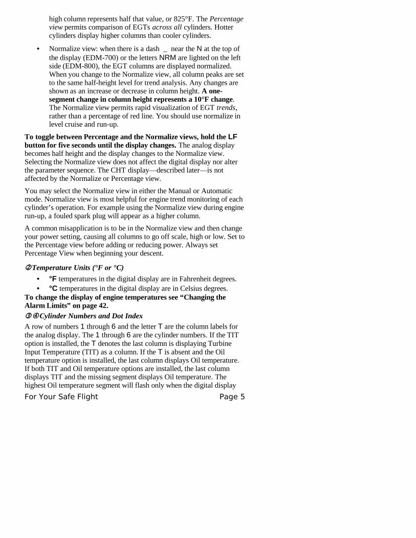
shows OIL. The highest TIT segment will flash on when the digital display shows TIT. A round dot under the numbers 1 through 6 indicates that particular column is shown numerically in the EGT and CHT digital display.
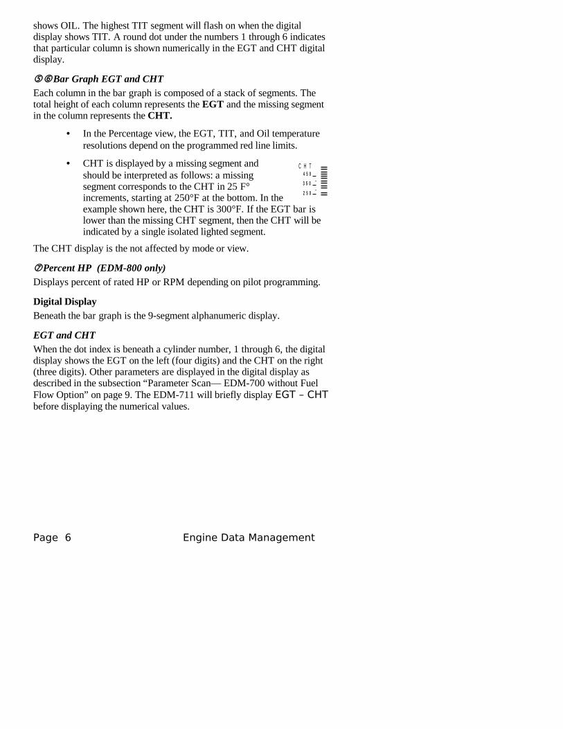
Bar Graph EGT and CHTEach column in the bar graph is composed of a stack of segments. The total height of each column represents the EGT and the missing segment in the column represents the CHT.
• In the Percentage view, the EGT, TIT, and Oil temperature resolutions depend on the programmed red line limits.
• CHT is displayed by a missing segment and should be interpreted as follows: a missing segment corresponds to the CHT in 25 F° increments, starting at 250°F at the bottom. In the example shown here, the CHT is 300°F. If the EGT bar is lower than the missing CHT segment, then the CHT will be indicated by a single isolated lighted segment.
The CHT display is the not affected by mode or view.
Percent HP (EDM-800 only)Displays percent of rated HP or RPM depending on pilot programming.
Digital DisplayBeneath the bar graph is the 9-segment alphanumeric display.
EGT and CHTWhen the dot index is beneath a cylinder number, 1 through 6, the digital display shows the EGT on the left (four digits) and the CHT on the right (three digits). Other parameters are displayed in the digital display as described in the subsection “Parameter Scan— EDM-700 without FuelFlow Option” on page 9. The EDM-711 will briefly display EGT – CHT before displaying the numerical values.
Page 6 Engine Data Management
2 5 0
3 5 0
4 5 0C H T
I 3 4 0 3 7 6S T E P L F
1 2 3 4 5 6 T7 3 H P
N R M F
E D M 8 0 0J P I
_E G T
%L i m i t
_2 5 0
3 5 0
4 5 0C H T
T S O
4 d i g i td i s p l a y o f
E G T
3 d i g i td i s p l a y o fC H T
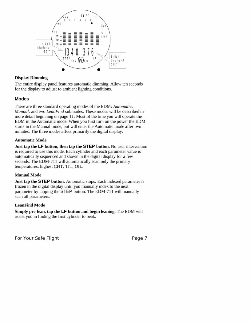
Display Dimming
The entire display panel features automatic dimming. Allow ten seconds for the display to adjust to ambient lighting conditions.
Modes
There are three standard operating modes of the EDM: Automatic, Manual, and two LeanFind submodes. These modes will be described in more detail beginning on page 11. Most of the time you will operate the EDM in the Automatic mode. When you first turn on the power the EDM starts in the Manual mode, but will enter the Automatic mode after two minutes. The three modes affect primarily the digital display.
Automatic Mode
Just tap the LF button, then tap the STEP button. No user intervention is required to use this mode. Each cylinder and each parameter value is automatically sequenced and shown in the digital display for a few seconds. The EDM-711 will automatically scan only the primary temperatures: highest CHT, TIT, OIL.
Manual Mode
Just tap the STEP button. Automatic stops. Each indexed parameter is frozen in the digital display until you manually index to the next parameter by tapping the STEP button. The EDM-711 will manually scan all parameters.
LeanFind Mode
Simply pre-lean, tap the LF button and begin leaning. The EDM will assist you in finding the first cylinder to peak.
For Your Safe Flight Page 7
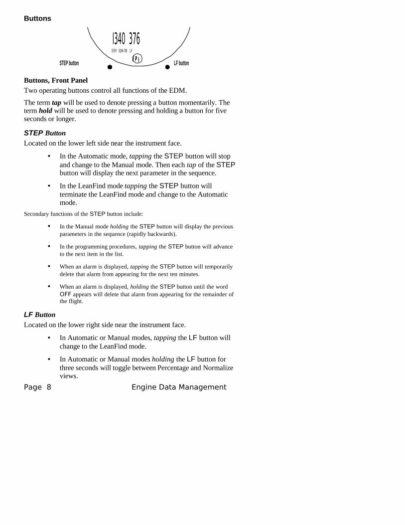
Buttons
I340 376STEP EDM-700 LF
J P ISTEP button LF button
Buttons, Front PanelTwo operating buttons control all functions of the EDM.
The term tap will be used to denote pressing a button momentarily. The term hold will be used to denote pressing and holding a button for five seconds or longer.
STEP ButtonLocated on the lower left side near the instrument face.
• In the Automatic mode, tapping the STEP button will stop and change to the Manual mode. Then each tap of the STEP button will display the next parameter in the sequence.
• In the LeanFind mode tapping the STEP button will terminate the LeanFind mode and change to the Automatic mode.
Secondary functions of the STEP button include:
• In the Manual mode holding the STEP button will display the previous parameters in the sequence (rapidly backwards).
• In the programming procedures, tapping the STEP button will advance to the next item in the list.
• When an alarm is displayed, tapping the STEP button will temporarily delete that alarm from appearing for the next ten minutes.
• When an alarm is displayed, holding the STEP button until the word OFF appears will delete that alarm from appearing for the remainder of the flight.
LF Button
Located on the lower right side near the instrument face.
• In Automatic or Manual modes, tapping the LF button will change to the LeanFind mode.
• In Automatic or Manual modes holding the LF button for three seconds will toggle between Percentage and Normalize views.
Page 8 Engine Data Management
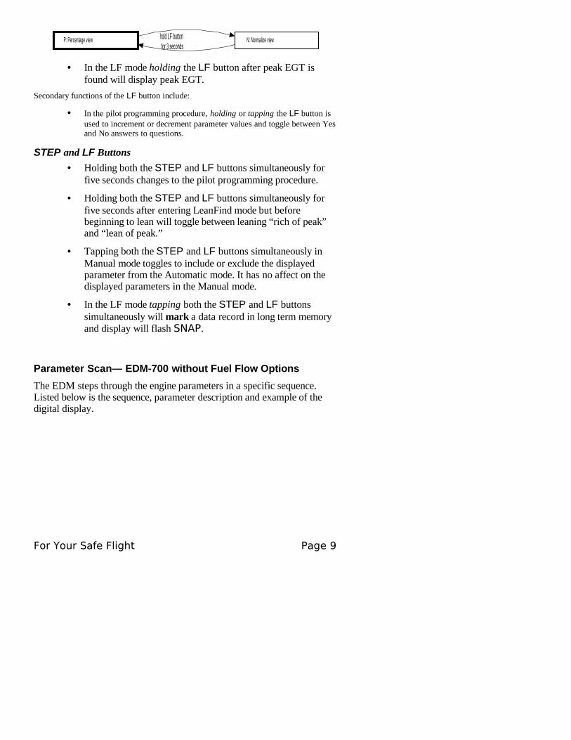
N: Normalize viewP: Percentage view hold LF button for 3 seconds
• In the LF mode holding the LF button after peak EGT is found will display peak EGT.
Secondary functions of the LF button include:
• In the pilot programming procedure, holding or tapping the LF button is used to increment or decrement parameter values and toggle between Yes and No answers to questions.
STEP and LF Buttons
• Holding both the STEP and LF buttons simultaneously for five seconds changes to the pilot programming procedure.
• Holding both the STEP and LF buttons simultaneously for five seconds after entering LeanFind mode but before beginning to lean will toggle between leaning “rich of peak” and “lean of peak.”
• Tapping both the STEP and LF buttons simultaneously in Manual mode toggles to include or exclude the displayed parameter from the Automatic mode. It has no affect on the displayed parameters in the Manual mode.
• In the LF mode tapping both the STEP and LF buttons simultaneously will mark a data record in long term memory and display will flash SNAP.
Parameter Scan— EDM-700 without Fuel Flow Options
The EDM steps through the engine parameters in a specific sequence. Listed below is the sequence, parameter description and example of the digital display.
For Your Safe Flight Page 9
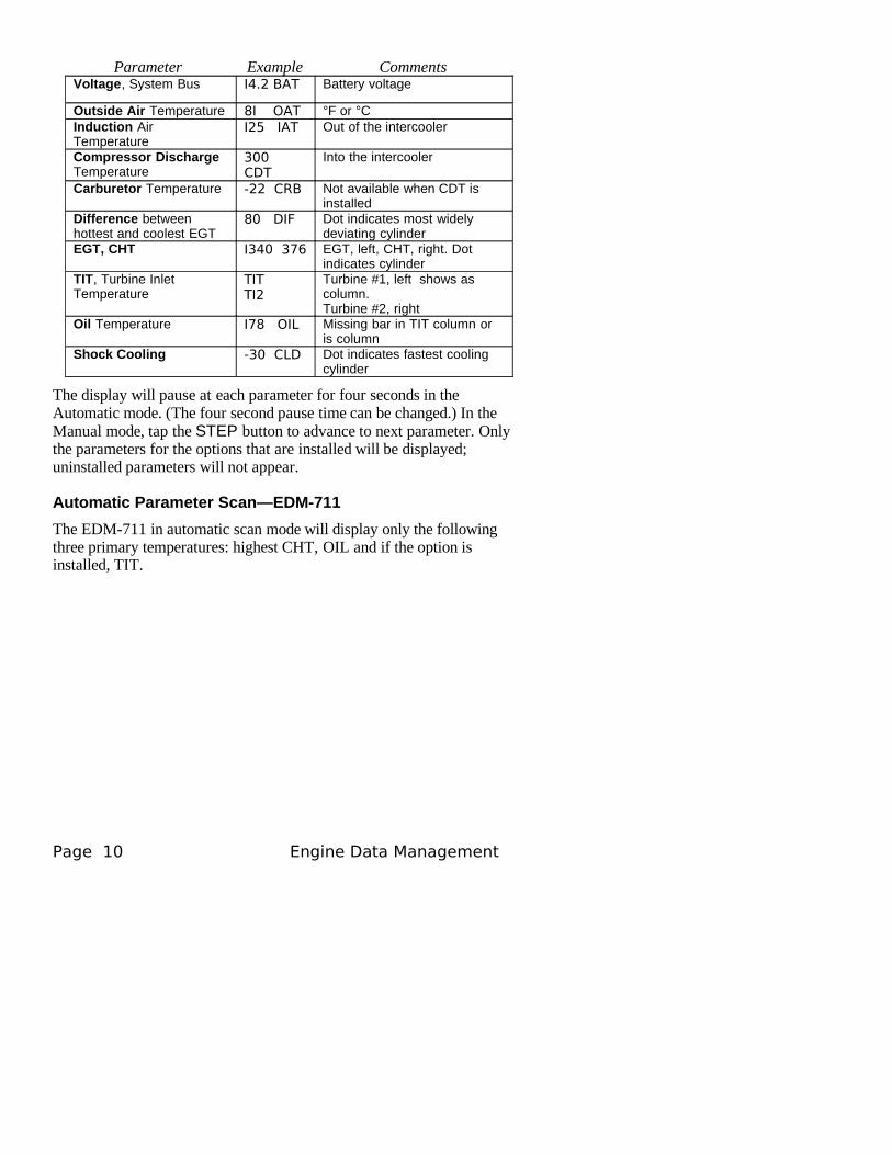
Parameter Example CommentsVoltage, System Bus I4.2 BAT Battery voltage
Outside Air Temperature 8I OAT °F or °CInduction Air Temperature
I25 IAT Out of the intercooler
Compressor Discharge Temperature
300 CDT
Into the intercooler
Carburetor Temperature -22 CRB Not available when CDT is installed
Difference between hottest and coolest EGT
80 DIF Dot indicates most widely deviating cylinder
EGT, CHT I340 376 EGT, left, CHT, right. Dot indicates cylinder
TIT, Turbine Inlet Temperature
TITTI2
Turbine #1, left shows as column.Turbine #2, right
Oil Temperature I78 OIL Missing bar in TIT column or is column
Shock Cooling -30 CLD Dot indicates fastest cooling cylinder
The display will pause at each parameter for four seconds in the Automatic mode. (The four second pause time can be changed.) In the Manual mode, tap the STEP button to advance to next parameter. Only the parameters for the options that are installed will be displayed; uninstalled parameters will not appear.
Automatic Parameter Scan—EDM-711
The EDM-711 in automatic scan mode will display only the following three primary temperatures: highest CHT, OIL and if the option is installed, TIT.
Page 10 Engine Data Management
Section 3 - Operating Procedures
Diagnostic Testing on Startup and During Flight
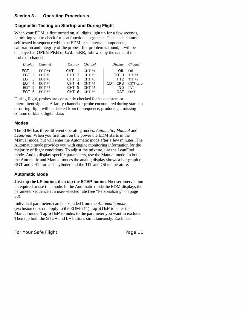
When your EDM is first turned on, all digits light up for a few seconds, permitting you to check for non-functional segments. Then each column is self-tested in sequence while the EDM tests internal components, calibration and integrity of the probes. If a problem is found, it will be displayed as OPEN PRB or CAL ERR, followed by the name of the probe or channel.
Display Channel Display Channel Display Channel
EGT I EGT #1 CHT I CHT #1 OIL OilEGT 2 EGT #2 CHT 2 CHT #2 TIT I TIT #1EGT 3 EGT #3 CHT 3 CHT #3 TIT2 TIT #2EGT 4 EGT #4 CHT 4 CHT #4 CDT CRB CDT carbEGT 5 EGT #5 CHT 5 CHT #5 IND IATEGT 6 EGT #6 CHT 6 CHT #6 OAT OAT
During flight, probes are constantly checked for inconsistent or intermittent signals. A faulty channel or probe encountered during start-up or during flight will be deleted from the sequence, producing a missing column or blank digital data.
Modes
The EDM has three different operating modes: Automatic, Manual and LeanFind. When you first turn on the power the EDM starts in the Manual mode, but will enter the Automatic mode after a few minutes. The Automatic mode provides you with engine monitoring information for the majority of flight conditions. To adjust the mixture, use the LeanFind mode. And to display specific parameters, use the Manual mode. In both the Automatic and Manual modes the analog display shows a bar graph of EGT and CHT for each cylinder and the TIT and Oil temperature.
Automatic Mode
Just tap the LF button, then tap the STEP button. No user intervention is required to use this mode. In the Automatic mode the EDM displays the parameter sequence at a user-selected rate (see “Personalizing” on page 33).
Individual parameters can be excluded from the Automatic mode (exclusion does not apply to the EDM-711): tap STEP to enter the Manual mode. Tap STEP to index to the parameter you want to exclude. Then tap both the STEP and LF buttons simultaneously. Excluded
For Your Safe Flight Page 11
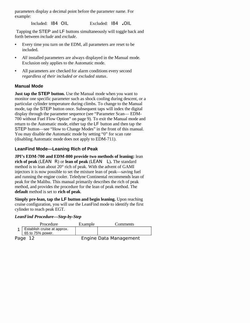
parameters display a decimal point before the parameter name. For example:
Included: I84 OIL Excluded: I84 .OIL
Tapping the STEP and LF buttons simultaneously will toggle back and forth between include and exclude.
• Every time you turn on the EDM, all parameters are reset to be included.
• All installed parameters are always displayed in the Manual mode. Exclusion only applies to the Automatic mode.
• All parameters are checked for alarm conditions every second regardless of their included or excluded status.
Manual Mode
Just tap the STEP button. Use the Manual mode when you want to monitor one specific parameter such as shock cooling during descent, or a particular cylinder temperature during climbs. To change to the Manual mode, tap the STEP button once. Subsequent taps will index the digital display through the parameter sequence (see “Parameter Scan— EDM-700 without Fuel Flow Option” on page 9). To exit the Manual mode and return to the Automatic mode, either tap the LF button and then tap the STEP button—see “How to Change Modes” in the front of this manual. You may disable the Automatic mode by setting “0” for scan rate (disabling Automatic mode does not apply to EDM-711).
LeanFind Mode—Leaning Rich of Peak
JPI’s EDM-700 and EDM-800 provide two methods of leaning: lean rich of peak (LEAN R) or lean of peak (LEAN L). The standard method is to lean about 20° rich of peak. With the advent of GAMI injectors it is now possible to set the mixture lean of peak—saving fuel and running the engine cooler. Teledyne Continental recommends lean of peak for the Malibu. This manual primarily describes the rich of peak method, and provides the procedure for the lean of peak method. The default method is set to rich of peak.
Simply pre-lean, tap the LF button and begin leaning. Upon reaching cruise configuration, you will use the LeanFind mode to identify the first cylinder to reach peak EGT.
LeanFind Procedure—Step-by-Step
Procedure Example Comments1 Establish cruise at approx.
65 to 75% power.
Page 12 Engine Data Management
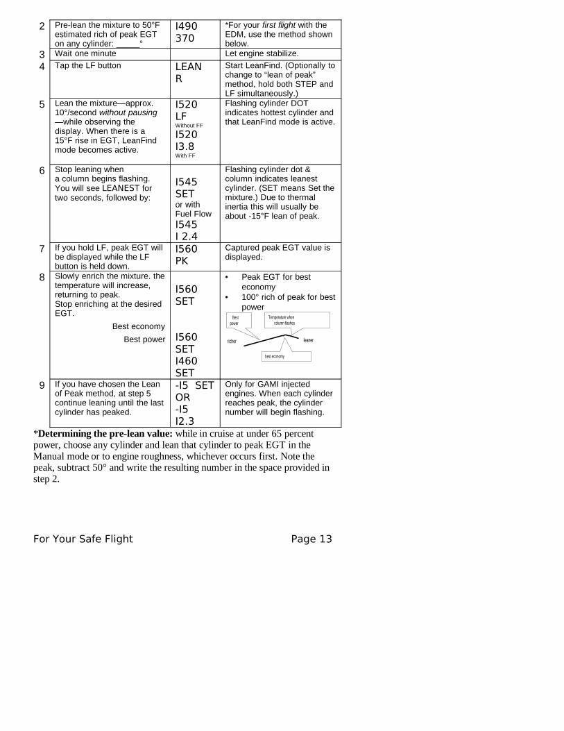
2 Pre-lean the mixture to 50°F estimated rich of peak EGT on any cylinder: _____°
I490 370
*For your first flight with the EDM, use the method shown below.
3 Wait one minute Let engine stabilize.
4 Tap the LF button LEAN R
Start LeanFind. (Optionally to change to “lean of peak” method, hold both STEP and LF simultaneously.)
5 Lean the mixture—approx. 10°/second without pausing—while observing the display. When there is a 15°F rise in EGT, LeanFind mode becomes active.
I520 LFWithout FF
I520 I3.8With FF
Flashing cylinder DOT indicates hottest cylinder and that LeanFind mode is active.
6 Stop leaning whena column begins flashing. You will see LEANEST for two seconds, followed by:
I545 SETor with Fuel Flow I545 I 2.4
Flashing cylinder dot & column indicates leanest cylinder. (SET means Set the mixture.) Due to thermal inertia this will usually be about -15°F lean of peak.
7 If you hold LF, peak EGT will be displayed while the LF button is held down.
I560 PK
Captured peak EGT value is displayed.
8 Slowly enrich the mixture. the temperature will increase, returning to peak.Stop enriching at the desired EGT.
Best economy
Best power
I560 SET
I560 SETI460 SET
• Peak EGT for best economy
• 100° rich of peak for best power
Bestpower
Temperature whencolumn flashes
best economy
leanerricher
9 If you have chosen the Lean of Peak method, at step 5 continue leaning until the last cylinder has peaked.
-I5 SETOR-I5 I2.3
Only for GAMI injected engines. When each cylinder reaches peak, the cylinder number will begin flashing.
*Determining the pre-lean value: while in cruise at under 65 percent power, choose any cylinder and lean that cylinder to peak EGT in the Manual mode or to engine roughness, whichever occurs first. Note the peak, subtract 50° and write the resulting number in the space provided in step 2.
For Your Safe Flight Page 13
LeanFind Procedure—General Explanation
Lycoming and Continental engines have established specific restrictions on leaning that must be followed, such as percentage of power, climb leaning, and TIT limits. Lycoming recommends operation at peak EGT for power settings of 75% or lower, while Continental recommends operation at peak EGT for power settings of 65% or lower. This guide is not meant to supersede any specific recommendations of the engine manufacturer or airframe manufacturer.
It is your responsibility to know your aircraft’s limitations.
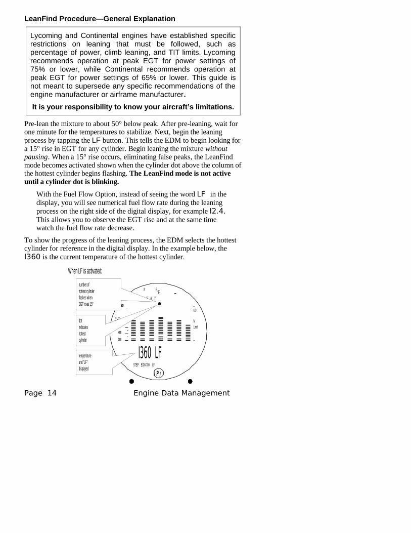
Pre-lean the mixture to about 50° below peak. After pre-leaning, wait for one minute for the temperatures to stabilize. Next, begin the leaning process by tapping the LF button. This tells the EDM to begin looking for a 15° rise in EGT for any cylinder. Begin leaning the mixture without pausing. When a 15° rise occurs, eliminating false peaks, the LeanFind mode becomes activated shown when the cylinder dot above the column of the hottest cylinder begins flashing. The LeanFind mode is not active until a cylinder dot is blinking.
With the Fuel Flow Option, instead of seeing the word LF in the display, you will see numerical fuel flow rate during the leaning process on the right side of the digital display, for example I2.4. This allows you to observe the EGT rise and at the same time watch the fuel flow rate decrease.
To show the progress of the leaning process, the EDM selects the hottest cylinder for reference in the digital display. In the example below, the I360 is the current temperature of the hottest cylinder.
I360 LFSTEP EDM-700 LF
° F1 2 3 4 5 6 T
N P
J P I
_
_EGT
%Limit
_300
400
500CHT
TSO
number ofhottest cylinderflashes whenEGT rises 15°
dotindicateshottestcylinder
temperatureand "LF"displayed
When LF is activated:
Page 14 Engine Data Management
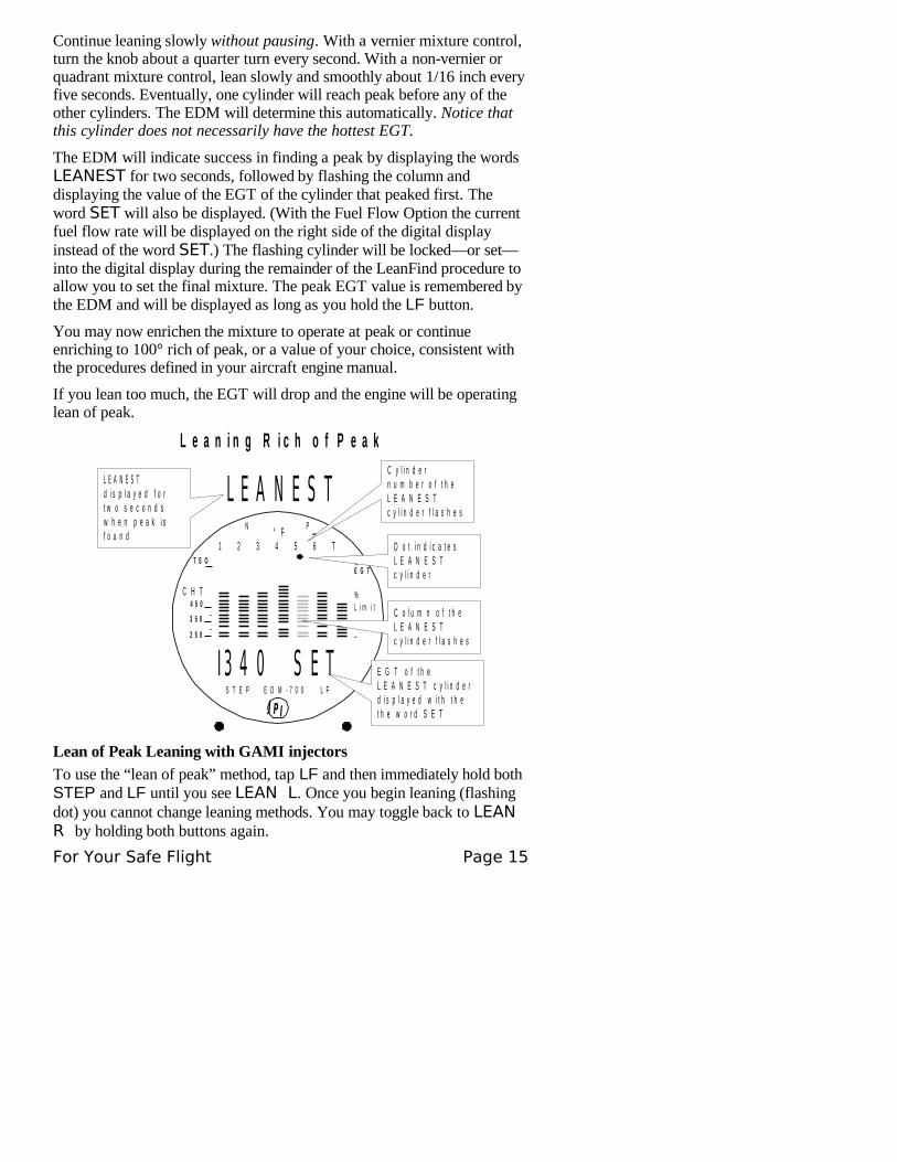
Continue leaning slowly without pausing. With a vernier mixture control, turn the knob about a quarter turn every second. With a non-vernier or quadrant mixture control, lean slowly and smoothly about 1/16 inch every five seconds. Eventually, one cylinder will reach peak before any of the other cylinders. The EDM will determine this automatically. Notice that this cylinder does not necessarily have the hottest EGT.
The EDM will indicate success in finding a peak by displaying the words LEANEST for two seconds, followed by flashing the column and displaying the value of the EGT of the cylinder that peaked first. The word SET will also be displayed. (With the Fuel Flow Option the current fuel flow rate will be displayed on the right side of the digital display instead of the word SET.) The flashing cylinder will be locked—or set—into the digital display during the remainder of the LeanFind procedure to allow you to set the final mixture. The peak EGT value is remembered by the EDM and will be displayed as long as you hold the LF button.
You may now enrichen the mixture to operate at peak or continue enriching to 100° rich of peak, or a value of your choice, consistent with the procedures defined in your aircraft engine manual.
If you lean too much, the EGT will drop and the engine will be operating lean of peak.
I 3 4 0 S E TS T E P E D M - 7 0 0 L F
° F1 2 3 4 5 6 T
N P
_
J P I
_
L E A N E S TL E A N E S Td i s p l a y e d f o rt w o s e c o n d sw h e n p e a k i sf o u n d
L e a n i n g R i c h o f P e a k
_E G T
%L i m i t
_2 5 0
3 5 0
4 5 0C H T
T S O
C y l i n d e rn u m b e r o f t h eL E A N E S Tc y l i n d e r f l a s h e s
D o t i n d i c a t e sL E A N E S Tc y l i n d e r
C o l u m n o f t h eL E A N E S Tc y l i n d e r f l a s h e s
E G T o f t h eL E A N E S T c y l i n d e rd i s p l a y e d w i t h t h et h e w o r d S E T
Lean of Peak Leaning with GAMI injectors
To use the “lean of peak” method, tap LF and then immediately hold both STEP and LF until you see LEAN L. Once you begin leaning (flashing dot) you cannot change leaning methods. You may toggle back to LEAN R by holding both buttons again.
For Your Safe Flight Page 15
Leaning Lean of Peak
-5 7.3
73 HP
1 2 3 4 5 6 T
_
STEP LFEDM 800J P I
_EGT
%Limit
_300
400
500CHT
TSO
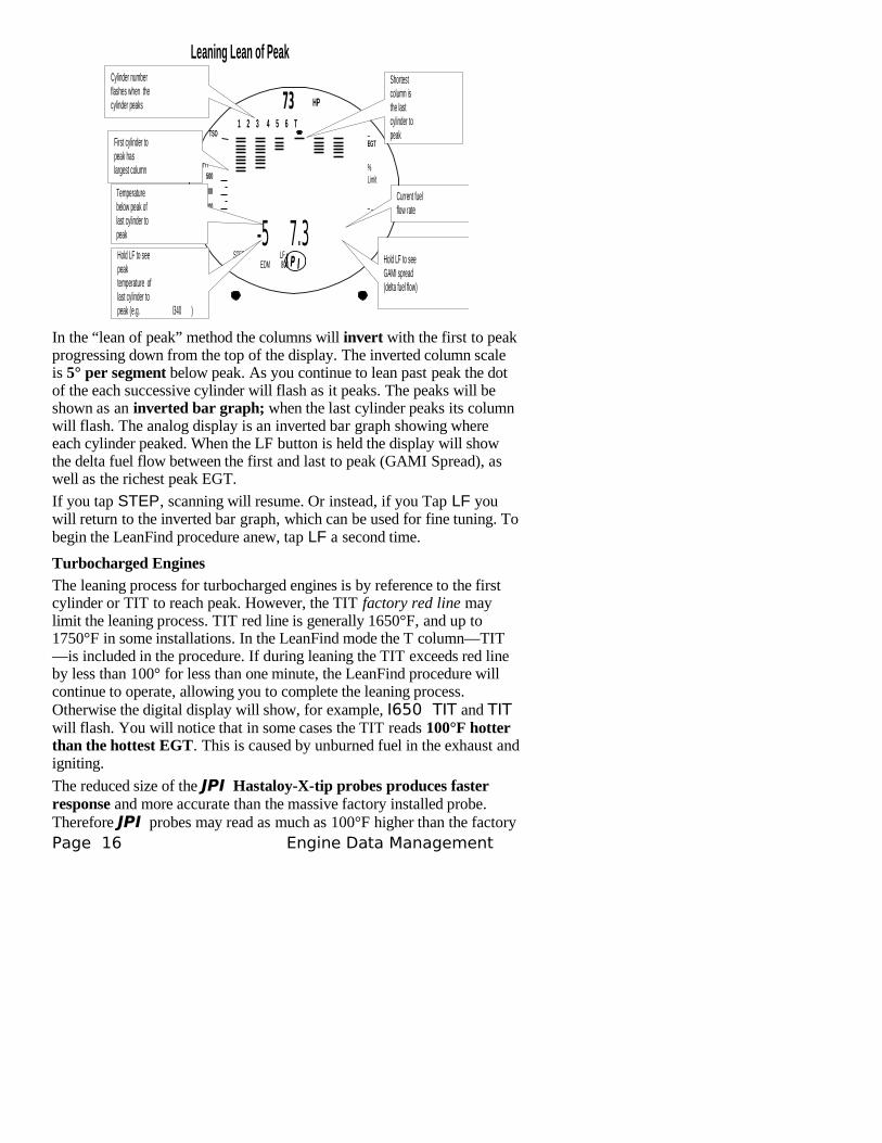
Cylinder numberflashes when thecylinder peaks
Temperaturebelow peak oflast cylinder topeak
Shortestcolumn isthe lastcylinder topeak
Current fuelflow rate
First cylinder topeak haslargest column
Hold LF to seepeaktemperature oflast cylinder topeak (e.g. I340 )
Hold LF to seeGAMI spread(delta fuel flow)
In the “lean of peak” method the columns will invert with the first to peak progressing down from the top of the display. The inverted column scale is 5° per segment below peak. As you continue to lean past peak the dot of the each successive cylinder will flash as it peaks. The peaks will be shown as an inverted bar graph; when the last cylinder peaks its column will flash. The analog display is an inverted bar graph showing where each cylinder peaked. When the LF button is held the display will show the delta fuel flow between the first and last to peak (GAMI Spread), as well as the richest peak EGT.
If you tap STEP, scanning will resume. Or instead, if you Tap LF you will return to the inverted bar graph, which can be used for fine tuning. To begin the LeanFind procedure anew, tap LF a second time.
Turbocharged Engines
The leaning process for turbocharged engines is by reference to the first cylinder or TIT to reach peak. However, the TIT factory red line may limit the leaning process. TIT red line is generally 1650°F, and up to 1750°F in some installations. In the LeanFind mode the T column—TIT—is included in the procedure. If during leaning the TIT exceeds red line by less than 100° for less than one minute, the LeanFind procedure will continue to operate, allowing you to complete the leaning process. Otherwise the digital display will show, for example, I650 TIT and TIT will flash. You will notice that in some cases the TIT reads 100°F hotter than the hottest EGT. This is caused by unburned fuel in the exhaust and igniting.
The reduced size of the JPI Hastaloy-X-tip probes produces faster response and more accurate than the massive factory installed probe. Therefore JPI probes may read as much as 100°F higher than the factory Page 16 Engine Data Management

installed probe. However, note that the engine was certified with the factory-installed probe and gauge, and this gauge reading is the limiting factor when adjusting your engine.
For Your Safe Flight Page 17
Operation for each Phase of Flight
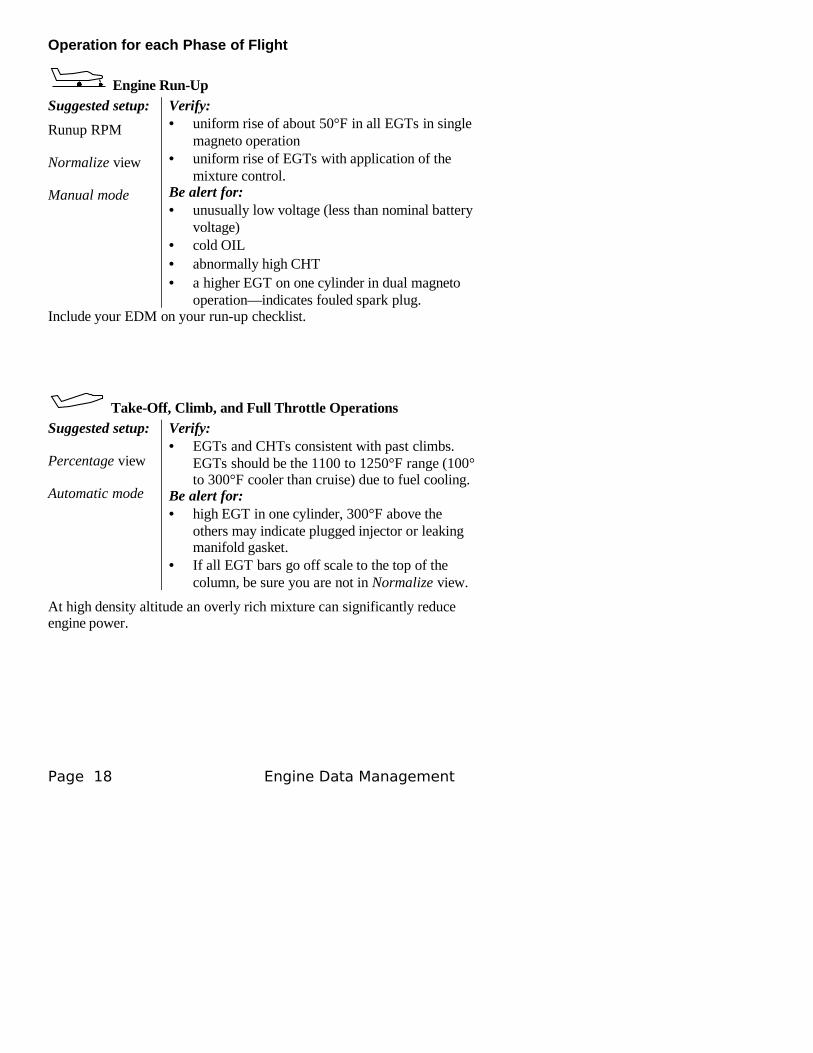
Engine Run-Up
Suggested setup:
Runup RPM
Normalize view
Manual mode
Verify:• uniform rise of about 50°F in all EGTs in single
magneto operation• uniform rise of EGTs with application of the
mixture control.Be alert for:• unusually low voltage (less than nominal battery
voltage)• cold OIL• abnormally high CHT• a higher EGT on one cylinder in dual magneto
operation—indicates fouled spark plug.Include your EDM on your run-up checklist.
Take-Off, Climb, and Full Throttle OperationsSuggested setup:
Percentage view
Automatic mode
Verify:• EGTs and CHTs consistent with past climbs.
EGTs should be the 1100 to 1250°F range (100° to 300°F cooler than cruise) due to fuel cooling.
Be alert for:• high EGT in one cylinder, 300°F above the
others may indicate plugged injector or leaking manifold gasket.
• If all EGT bars go off scale to the top of the column, be sure you are not in Normalize view.
At high density altitude an overly rich mixture can significantly reduce engine power.
Page 18 Engine Data Management
Cruise
After the engine is warmed up, use LeanFind to lean the mixture.
Suggested setup:
Percentage view
Automatic mode
Be alert for:• uneven EGTs or CHTs (carbureted engines).
Make fine adjustments to throttle, then RPM, then mixture to level the display columns.
• abnormal patterns of EGTs and CHT. (see “Diagnosing Engine Problems” on page 21).
DescentSuggested setup:
Percentage view
Manual mode
Be alert for:• CLD: shock cooling alarm is set to –60°F.
Average cool rates of –40°F/minute to–60°F/minute are normal, depending on the engine size.
Shock Cooling
Cooling the cylinders too fast can result in cracking and eventual failure. Lycoming Service Instruction 1094D (March 25, 1994) on Fuel Mixture Leaning Procedures states:
“At all times, caution must be taken not to shock cool the cylinders. The maximum recommended temperature change should not exceed 50°F per minute.”
JPI checks shock cooling on all cylinders displaying the highest reading cylinder.
For Your Safe Flight Page 19
Common Misapplications
Some of the more common misapplications made by first-time EDM users are presented here in an attempt to help you avoid similar problems.
Problem Situation Correction
LeanFind finds a “peak” too soon.
Failure to pre-lean before performing LeanFind or stopping while leaning.
Follow the pre-lean procedure in the section “LeanFind Mode” on page 12.
Leaning too slowly. Lean more quickly.
Peak not found Lean Find not activated or stopping while leaning
Lean at the speed of approximately 10°F per second.
Off-scale EGT bars, too high or low
You forgot that you set the EDM in the Normalize view and later observe off-scale EGT bar readings.
The higher sensitivity (10° per segment) of the Normalize view can quickly go too high or low off-scale with only small changes in EGT.
First cylinder to peak is not the hottest
This is normal. The first to cylinder peak is not necessarily the hottest.
EGTs rise during single magneto check
This is normal, due to incomplete combustion persisting longer.
EGTs not uniform during low power operation
This is normal. Fuel and air distribution is not optimal at low power settings.
No display of %HP
Fuel flow not reading Fuel Flow option is required for HP
Page 20 Engine Data Management
Section 4 - Diagnosing Engine Problems
Typical Normal ParametersThe follow chart lists typical normal parameter values that you will observe for most general aircraft engines.
Parameter Normal range Comments
EGTs in Cruise 1350°F1550°F
• under 200 HP• high performance• EGT should drop 200°F
when full throttle is applied
EGT span (DIF) 70 to 90°F120 to 150°F
• fuel injected• carbureted
TIT 1600°F average • 100° higher than EGT
CHTs 350°F (OAT 60°F)410°F
• normally aspirated• Turbocharged
CHT span 50 to 70°F 100° with gasket probes
OIL 200°F • oil cooler thermostat opens at 180°F
Shock cooling* -40°/minute-55°/minute
-200°/minute
• tightly cowled• Bonanza• helicopter
* Maintain a cooling rate of less than -60°/minute. You will find that the cylinder with the greatest shock cooling will shift from front cylinders (during climb out) to the rear cylinders (during descent ).
If one CHT is reading 20° to 50° above or below the others, this may be due to that cylinder having a spark plug gasket probe instead of a bayonet probe. This is necessary because the aircraft’s factory original CHT probe is occupying the socket in the cylinder head rather than the EDM. This is normal. If the discrepancy is greater, be sure the spark plug gasket probe is mounted on the top spark plug. An adapter probe is available to occupy the same socket as the factory original probe. Contact your dealer.
For Your Safe Flight Page 21
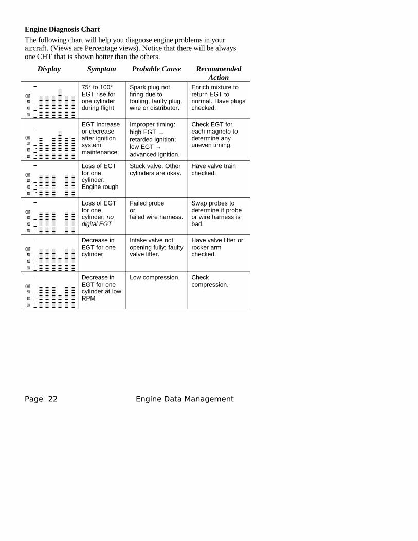
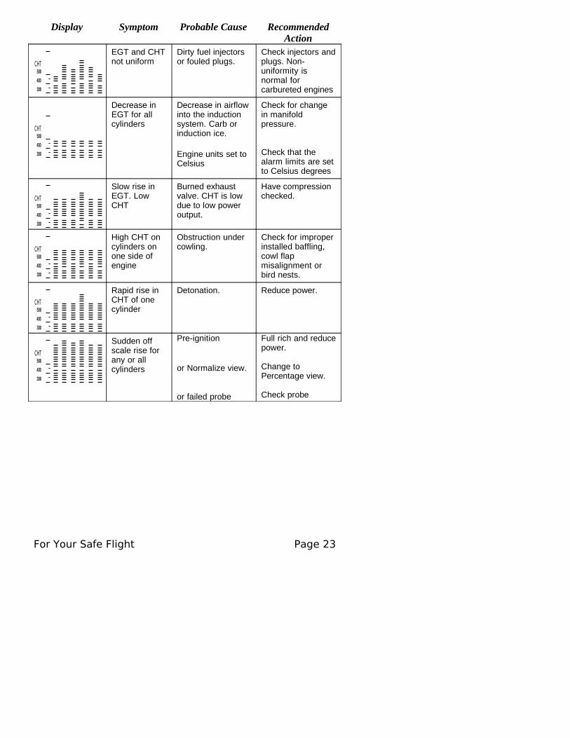
Engine Diagnosis Chart
The following chart will help you diagnose engine problems in your aircraft. (Views are Percentage views). Notice that there will be always one CHT that is shown hotter than the others.
Display Symptom Probable Cause Recommended Action
CHT
300
400
500
75° to 100° EGT rise for one cylinder during flight
Spark plug not firing due to fouling, faulty plug, wire or distributor.
Enrich mixture to return EGT to normal. Have plugs checked.
CHT
300
400
500
EGT Increase or decrease after ignition system maintenance
Improper timing: high EGT → retarded ignition; low EGT → advanced ignition.
Check EGT for each magneto to determine any uneven timing.
CHT
300
400
500
Loss of EGT for one cylinder. Engine rough
Stuck valve. Other cylinders are okay.
Have valve train checked.
CHT
300
400
500
Loss of EGT for one cylinder; no digital EGT
Failed probeorfailed wire harness.
Swap probes to determine if probeor wire harness is bad.
CHT
300
400
500
Decrease in EGT for one cylinder
Intake valve not opening fully; faulty valve lifter.
Have valve lifter or rocker arm checked.
CHT
300
400
500
Decrease in EGT for one cylinder at low RPM
Low compression. Check compression.
Page 22 Engine Data Management
Display Symptom Probable Cause Recommended Action
CHT
300
400
500
EGT and CHT not uniform
Dirty fuel injectors or fouled plugs.
Check injectors and plugs. Non-uniformity is normal for carbureted engines
CHT
300
400
500
Decrease in EGT for all cylinders
Decrease in airflow into the induction system. Carb or induction ice.
Engine units set to Celsius
Check for change in manifold pressure.
Check that the alarm limits are set to Celsius degrees
CHT
300
400
500
Slow rise in EGT. Low CHT
Burned exhaust valve. CHT is low due to low power output.
Have compression checked.
CHT
300
400
500
High CHT on cylinders on one side of engine
Obstruction under cowling.
Check for improper installed baffling, cowl flap misalignment or bird nests.
CHT
300
400
500
Rapid rise in CHT of one cylinder
Detonation. Reduce power.
CHT
300
400
500
Sudden off scale rise for any or all cylinders
Pre-ignition
or Normalize view.
or failed probe
Full rich and reduce power.
Change to Percentage view.
Check probe
For Your Safe Flight Page 23
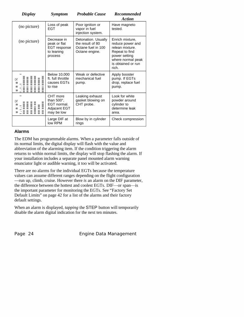
Display Symptom Probable Cause Recommended Action
(no picture) Loss of peak EGT
Poor ignition or vapor in fuel injection system.
Have magneto tested.
(no picture) Decrease in peak or flat EGT response to leaning process
Detonation. Usually the result of 80 Octane fuel in 100 Octane engine.
Enrich mixture, reduce power and relean mixture. Repeat to find power setting where normal peak is obtained or run rich.
CHT
300
400
500
Below 10,000 ft. full throttle causes EGTs to rise
Weak or defective mechanical fuel pump.
Apply booster pump. If EGTs drop, replace fuel pump.
CHT
300
400
500
CHT more than 500°, EGT normal. Adjacent EGT may be low
Leaking exhaust gasket blowing on CHT probe.
Look for white powder around cylinder to determine leak area.
Large DIF at low RPM
Blow by in cylinder rings
Check compression
Alarms
The EDM has programmable alarms. When a parameter falls outside of its normal limits, the digital display will flash with the value and abbreviation of the alarming item. If the condition triggering the alarm returns to within normal limits, the display will stop flashing the alarm. If your installation includes a separate panel mounted alarm warning enunciator light or audible warning, it too will be activated.
There are no alarms for the individual EGTs because the temperature values can assume different ranges depending on the flight configuration—run up, climb, cruise. However there is an alarm on the DIF parameter, the difference between the hottest and coolest EGTs. DIF—or span—is the important parameter for monitoring the EGTs. See “Factory SetDefault Limits” on page 42 for a list of the alarms and their factory default settings.
When an alarm is displayed, tapping the STEP button will temporarily disable the alarm digital indication for the next ten minutes.
Page 24 Engine Data Management
When an alarm is displayed, holding the STEP button until the word OFF appears will disable that alarm digital indication for the remainder of the flight. See “Alarm Limits” on page 41.
EDM-711 primary alarm display lamps cannot be disabled.
Alarm Priority
If multiple alarms occur simultaneously, the higher priority alarm will temporarily “mask” the lower priority alarm(s). When an alarm occurs, note the cause of the alarm and tap the STEP button to clear the alarm indication so that you will be notified of any other alarm that might have occurred. The alarm priorities are as follows:
Highest priority CHT High CHT OIL High OIL temperature TIT High TITOIL Low OIL temperature CLD Excessive CHT cooling rateDIF Excessive EGT spanBAT High battery voltageBAT Low battery voltageMAP Overboost Manifold pressure
LO FUEL
Low fuel quantity remaining
Lowest priority LO TIME
Low fuel endurance remaining
Pre-Ignition and Detonation
Combustion that is too rapid leads to detonation and possibly pre-ignition. Detonation is abnormally rapid combustion where the fuel-air mixture explodes instead of burning uniformly. It causes the EGT to decrease and the CHT to increase, and can appear during the leaning process. It occurs under high compression from fuel with too low an octane rating, or from avgas contaminated by jet fuel. Fuel additives, such as lead, boost the octane rating and slow down the combustion process, producing an even pressure to the piston.
Pre-ignition is caused by hot spots in the cylinder. Ignition occurs prior to the spark plug firing. The EDM depicts pre-ignition as a sudden red line of the EGT on the analog display. This may occur in one or more cylinders. The affected cylinder column(s) will flash while the digital display will show an EGT higher than 2000°F. At this temperature pre-ignition will destroy your engine in less than a minute unless you take immediate corrective action.
For Your Safe Flight Page 25
Section 5 - Fuel Flow Option Operation
Fuel Flow Display Select Switch
The select switch is a three-position toggle switch mounted on your instrument panel near the display of the EDM. It affects only the display scan.
• In the EGT (Temperature) position only the installed temperature (and battery voltage) parameters are displayed.
• In the ALL (All) position, the EDM both installed temperature and fuel flow parameters are displayed.
• In the FF (Fuel Flow) position only fuel flow parameters are displayed.
Any alarm warning will appear regardless of the select switch setting. These parameters are displayed in the digital display in either the Automatic or Manual modes or during the pilot programming procedure. The select switch does not effect the analog display. EDM-711: the toggle switch is disabled during Automatic scan mode.
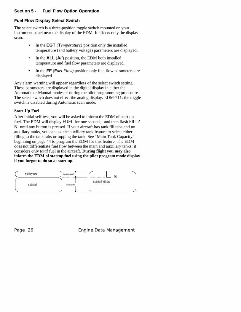
Start Up FuelAfter initial self-test, you will be asked to inform the EDM of start up fuel. The EDM will display FUEL for one second, and then flash FILL? N until any button is pressed. If your aircraft has tank fill tabs and no auxiliary tanks, you can use the auxiliary tank feature to select either filling to the tank tabs or topping the tank. See “Main Tank Capacity” beginning on page 44 to program the EDM for this feature. The EDM does not differentiate fuel flow between the main and auxiliary tanks; it considers only total fuel in the aircraft. During flight you may also inform the EDM of startup fuel using the pilot program mode display if you forgot to do so at start up.
main tank
auxiliary tank
main tank with tab
tabAuxiliary capacity
Main capacity
Page 26 Engine Data Management
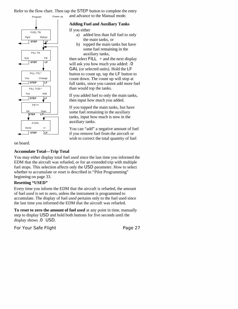
Refer to the flow chart. Then tap the STEP button to complete the entry and advance to the Manual mode.
Adding Fuel and Auxiliary Tanks
If you eithera) added less than full fuel to only
the main tanks, orb) topped the main tanks but have
some fuel remaining in the auxiliary tanks,
then select FILL + and the next display will ask you how much you added: .0 GAL (or selected units). Hold the LF button to count up, tap the LF button to count down. The count up will stop at full tanks, since you cannot add more fuel than would top the tanks.
If you added fuel to only the main tanks, then input how much you added.
If you topped the main tanks, but have some fuel remaining in the auxiliary tanks, input how much is now in the auxiliary tanks.
You can “add” a negative amount of fuel if you remove fuel from the aircraft or wish to correct the total quantity of fuel
on board.
Accumulate Total—Trip TotalYou may either display total fuel used since the last time you informed the EDM that the aircraft was refueled, or for an extended trip with multiple fuel stops. This selection affects only the USD parameter. How to select whether to accumulate or reset is described in “Pilot Programming” beginning on page 33.
Resetting “USED”Every time you inform the EDM that the aircraft is refueled, the amount of fuel used is set to zero, unless the instrument is programmed to accumulate. The display of fuel used pertains only to the fuel used since the last time you informed the EDM that the aircraft was refueled.
To reset to zero the amount of fuel used at any point in time, manually step to display USD and hold both buttons for five seconds until the display shows .0 USD.
For Your Safe Flight Page 27
Power up
FUEL ?N
Pgm Refuel
Program
FILL ?N
FILL ?75 *
Yes Change
Fill ?+
OK Start
Exit Fill
.0 GAL
Done +/-
FILL ?120 *
Yes Add
STEP LF
STEP LF
STEP LF
STEP LF
STEP LF
STEP LF
Fuel Management
Without a means of measuring fuel flow, you must rely on the aircraft fuel gauges or total time of flight. Aircraft fuel gauges are notoriously inaccurate (they are only required by the FAA to read accurately when displaying empty). And measuring time of flight is only an approximation, and assumes a constant fuel flow rate for each phase of flight.
The EDM Fuel Flow Option uses a small, turbine transducer that measures the fuel flowing into the engine. Higher fuel flow causes the transducer turbine to rotate faster which generates a faster pulse rate. Because the transducer turbine generates thousands of pulses per gallon of fuel, it can measure with high resolution the amount of fuel that flows into the engine. Prior to engine start you inform the EDM Fuel Flow Option of the known quantity of fuel aboard, and it will keep track of all fuel delivered to the engine.
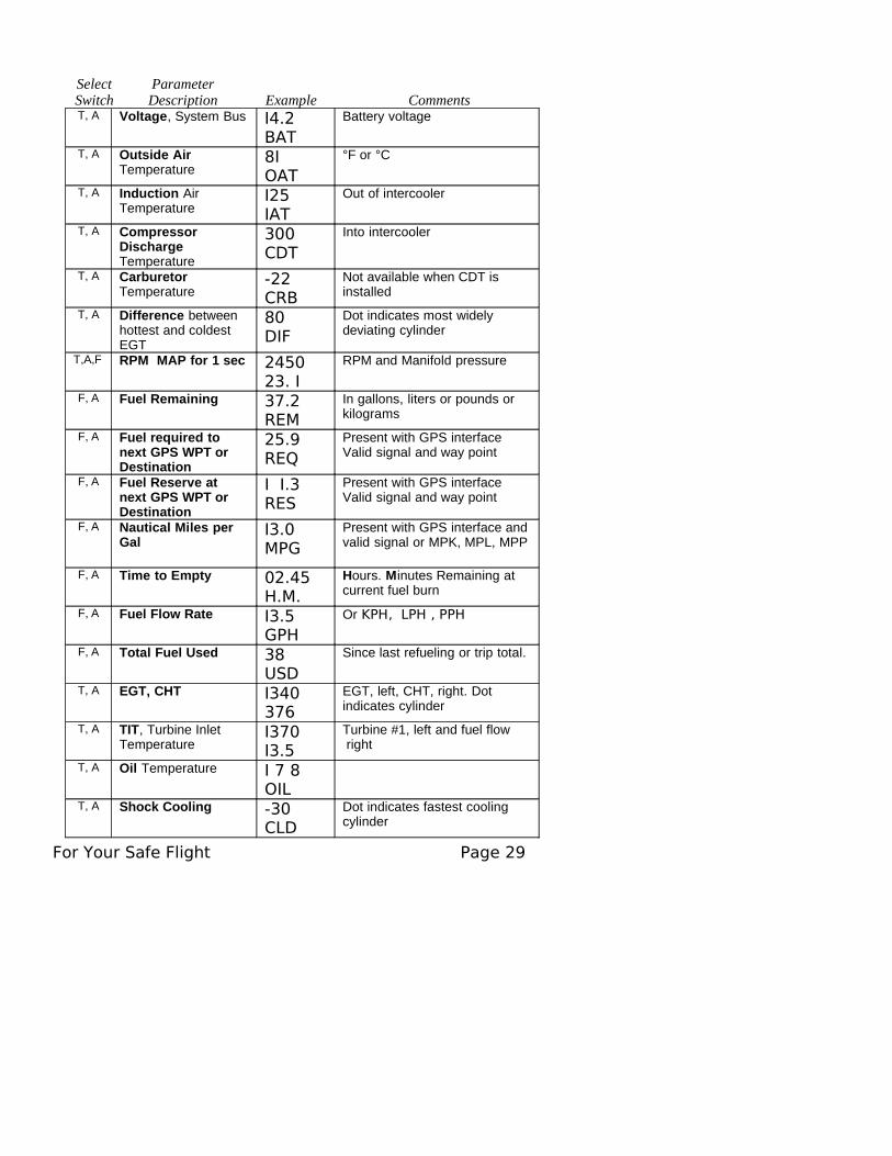
Parameter Scan—Systems with Fuel Flow Option
Listed below is the sequence, parameter description and example of the digital display. The first column indicates what position the select switch must be in to display that particular parameter. T is EGT, F is FF and A is ALL.
Page 28 Engine Data Management
Select Switch
Parameter Description Example Comments
T, A Voltage, System Bus I4.2 BAT
Battery voltage
T, A Outside Air Temperature
8I OAT
°F or °C
T, A Induction Air Temperature
I25 IAT
Out of intercooler
T, A Compressor Discharge Temperature
300 CDT
Into intercooler
T, A Carburetor Temperature
-22 CRB
Not available when CDT is installed
T, A Difference between hottest and coldest EGT
80 DIF
Dot indicates most widely deviating cylinder
T,A,F RPM MAP for 1 sec 2450 23. I
RPM and Manifold pressure
F, A Fuel Remaining 37.2 REM
In gallons, liters or pounds or kilograms
F, A Fuel required to next GPS WPT or Destination
25.9 REQ
Present with GPS interface Valid signal and way point
F, A Fuel Reserve at next GPS WPT or Destination
I I.3 RES
Present with GPS interface Valid signal and way point
F, A Nautical Miles per Gal
I3.0 MPG
Present with GPS interface and valid signal or MPK, MPL, MPP
F, A Time to Empty 02.45 H.M.
Hours. Minutes Remaining at current fuel burn
F, A Fuel Flow Rate I3.5 GPH
Or KPH, LPH , PPH
F, A Total Fuel Used 38 USD
Since last refueling or trip total.
T, A EGT, CHT I340 376
EGT, left, CHT, right. Dot indicates cylinder
T, A TIT, Turbine Inlet Temperature
I370 I3.5
Turbine #1, left and fuel flow right
T, A Oil Temperature I 7 8 OIL
T, A Shock Cooling -30 CLD
Dot indicates fastest cooling cylinder
For Your Safe Flight Page 29
For fuel calculations to be accurate, it is imperative that you inform the EDM of the correct amount of fuel aboard the aircraft. Do not rely on fuel flow instruments to determine fuel levels in tanks. Refer to original fuel flow instrumentation for primary information
Section 6 - Long Term Data Memory
The EDM Long Term Data Memory will record and store all displayed parameters once every six seconds (or at the programmed interval of between 2 to 500 seconds). At a later time it will transfer them directly to a laptop PC.
When you retrieve recorded data to your laptop PC you can choose to retrieve all the data in stored in the EDM, or only the new data recorded since your last retrieval. In either case, no data in the EDM is erased. The data will be saved in the PC in a file in a compressed format. The PC program supplied with the Long Term Data Memory will decompress the data for display.
The amount of total data that the EDM can store will vary depending on how rapidly the measured temperatures change. The typical storage is up to 20 hours at a 6 second interval (1600 hours at 8 minute interval), but may vary depending on which options are installed. When the memory becomes full, the oldest data will be discarded to make room for the newest. In the LeanFind mode you may place a mark at the next data record by tapping both the STEP and LF buttons simultaneously. You will see the word SNAP within the next six seconds, indicating a data record has been marked. Tap the STEP button to return to the Automatic mode. Recording begins when EGTs are greater than 500°F or “snap” is requested.
All data are time-stamped. The EDM Long Term Data Memory contains a real-time clock that may be reset to local time when you initially program your instrument. You may also program an aircraft id that will appear in the output data file. The aircraft id can be your aircraft registration number or your name. Initially the aircraft ID is set to the EDM's serial number.
You may change the record interval from 2 to 500 seconds, even in flight. When you change the interval in flight, the current flight file is closed, and a new flight file is created with the new record interval.
At power on, the EDM will execute its self test and then display the date (e.g., I I. I2.0 I), the time (I3.26), the percentage of memory filled since the last save (FULL 24), and the Aircraft ID.
Page 30 Engine Data Management
Downloading from Long Term Memory
To download data from the long term memory to your laptop PC, do the following steps.
1. Connect the data cable between the PC serial port and the EDM data port connector mounted on your instrument panel.
2. Run the EzPlot program on the PC.
3. On the EDM hold both STEP and LF for five seconds.
4. Tap STEP a number of times until you see DUMP? N.
5. Tap LF to select NEW data or ALL data.
6. Click on the Start button on the PC.
7. Wait 2 seconds and tap STEP on the EDM.
At the completion of the download, you can plot the data. Refer to the EzPlot program and documentation.
Downloading Data from the EDM to a Flash Drive
Using the Accessory USB Memory Box
To download EDM data into a USB flash drive using the accessory USB memory box, follow these instructions.
1. Insert the serial cable plug into the front panel of the EDM. Insert the other end of the serial data cable into the 9-pin jack on the memory box. (The serial cable is supplied with the EDM, not the memory box.)
For Your Safe Flight Page 31
2. Turn on the power switch on the memory box; the red light on the memory box will light up.
3.Insert the USB flash drive into the USB port on the memory box. The green light on the memory box will light up. If so equipped, the active light on the USB flash drive will light up.
4.You should see DUMPNEW on the EDM display. If you want to dump only new data since the last download, tap the STEP button. If you want all the data in the EDM, first tap the LF button and see DUMPALL. Then tap STEP.
5.During the download, the EDM will display DATA DOWNLOAD MODE and the percent complete indicator will progress from 0% to 100%. The green light on the memory box should blink and the active light on the USB flash drive will blink.
6.When the download is complete the EDM display will show DONE. Wait 10 seconds.
7.Remove the USB flash drive from the memory box, turn off the memory box, and disconnect the cable from the EDM.
This completes the download. See “Downloading from USB Flash Driveto a PC,” below.
Using the Optional USB PortTo download EDM data into a USB flash drive using the optional USB port, follow these instructions.
1.With the EDM powered up, plug the USB flash drive into the USB connector on the aircraft instrument panel. The EDM display will show NEW.
2.If you want to dump only new data since the last download, tap the STEP button. If you want all the data in the EDM, first tap the LF button and see ALL. Then tap STEP.
3. You will see a count down as the data is copied to the USB flash drive. When the download is complete the display on the EDM will show DONE.
4.Remove the USB flash drive from the USB connector.
This completes the download. Continue to the next step.
Downloading from USB Flash Drive to a PC
To download your data from the USB flash drive to your PC, follow these easy steps.
1.On your PC, start the EzTrends program.2.Plug in the USB flash drive into an available USB port.
Page 32 Engine Data Management
3.In EzTrends, select the Move and Plot Data from Memory Stick option.
4.In the displayed list, find the USB flash drive and double click it.5.Select the file you wish to plot and then select the flight in that file.
Refer to the EzTrends manual for details on how to use EzTrends.
Section 7 - Personalizing
Pilot Programming
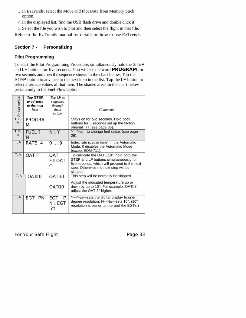
To start the Pilot Programming Procedure, simultaneously hold the STEP and LF buttons for five seconds. You will see the word PROGRAM for two seconds and then the sequence shown in the chart below. Tap the STEP button to advance to the next item in the list. Tap the LF button to select alternate values of that item. The shaded areas in the chart below pertain only to the Fuel Flow Option.
Sel
ect
switc
h Tap STEP to advance to the next
item
Tap LF to sequence through
these values
Comments
T, F, A
PROGRAM
Stays on for two seconds. Hold both buttons for 5 seconds set up the factory original TIT (see page 36).
T, F, A
FUEL ? N
N Y Y—Yes—to change fuel status (see page 26).
T, A RATE 4 0 … 9 Index rate (pause time) in the Automatic Mode. 0 disables the Automatic Mode (except EDM-711).
T, A OAT F OAT F OAT C
To calibrate the OAT ±10°, hold both the STEP and LF buttons simultaneously for five seconds, which will proceed to the next step. Otherwise the next step will be skipped.
T, A OAT 0 OAT-I0 … OAT I0
This step will be normally be skipped.
Adjust the indicated temperature up or down by up to 10°. For example, OAT 3 adjust the OAT 3° higher.
T, A EGT I?N EGT I?N EGT I?Y
Y—Yes—sets the digital display to one-degree resolution; N—No—sets 10°. (10° resolution is easier to interpret the EGTs.)
For Your Safe Flight Page 33
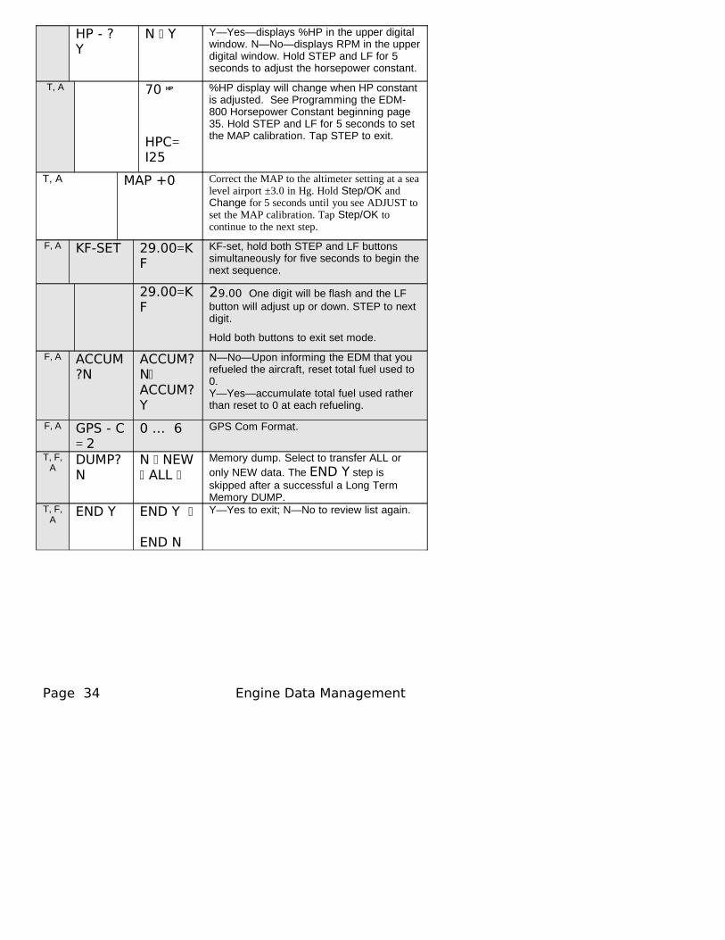
HP - ? Y
N Y Y—Yes—displays %HP in the upper digital window. N—No—displays RPM in the upper digital window. Hold STEP and LF for 5 seconds to adjust the horsepower constant.
T, A 70 HP
HPC= I25
%HP display will change when HP constant is adjusted. See Programming the EDM-800 Horsepower Constant beginning page 35. Hold STEP and LF for 5 seconds to set the MAP calibration. Tap STEP to exit.
T, A MAP +0 Correct the MAP to the altimeter setting at a sea level airport ±3.0 in Hg. Hold Step/OK and Change for 5 seconds until you see ADJUST to set the MAP calibration. Tap Step/OK to continue to the next step.
F, A KF-SET 29.00=KF
KF-set, hold both STEP and LF buttons simultaneously for five seconds to begin the next sequence.
29.00=KF
29.00 One digit will be flash and the LF button will adjust up or down. STEP to next digit.
Hold both buttons to exit set mode.
F, A ACCUM?N
ACCUM?NACCUM?Y
N—No—Upon informing the EDM that you refueled the aircraft, reset total fuel used to 0.Y—Yes—accumulate total fuel used rather than reset to 0 at each refueling.
F, A GPS - C = 2
0 … 6 GPS Com Format.
T, F, A
DUMP? N
N NEW ALL
Memory dump. Select to transfer ALL or only NEW data. The END Y step is skipped after a successful a Long Term Memory DUMP.
T, F, A
END Y END Y
END N
Y—Yes to exit; N—No to review list again.
Page 34 Engine Data Management
Section 8 - Programming the EDM-800 Horsepower Constant
You must adjust the HP Constant once for your aircraft. The default display will be RPM if Fuel Flow is not operational or you can adjust the display to show RPM instead of HP. Before takeoff, put the EDM in the HP Constant mode. Enter the pilot program mode by simultaneously holding the STEP and LF buttons until the display changes, about 5 seconds.
1. Tap STEP about 4 times until you see HP-? Y. If you see HP-? N, change the N to a Y by tapping the LF button, then hold both the STEP and LF buttons display until you see HPC= I20. Change the number 120 by tapping or holding the LF button. Note that the %HP number in the display will change as you change the constant.
2. Referring to the Aircraft Flight Manual (AFM) set the engine to a constant power setting of 70% , Rich of peak and maintain straight and level flight at any altitude below 10,000 feet. View the reading in the %HP display and see how close it is to your current engine percent HP. If the value in the display not at your current engine percent HP setting, then change the HP reading by adjusting the HP constant in the lower display by holding or tapping the LF button. Note: the reading is the percent of maximum HP, not total HP.
3. Keep adjusting the HP constant until the upper window displays the same power level as the current engine percent HP.
4. Tap the STEP button to exit.
Section 9 - Programming Manifold Pressure (MAP)
Do this one time and only if the MAP on your manifold pressure gauge doesn't match the MAP shown on the EDM-800.
1. Do this on the ground with the engine turned off.
2. Enter the pilot program mode by simultaneously holding the STEP and LF buttons for five seconds.
3. Tap STEP to index to HP-? Y.
4. Hold both the STEP and LF buttons and you will see HPC= I25.
5. Hold both the STEP and LF buttons and you will see MAP= 0
6. Use one of the following two methods to calibrate the MAP.
For Your Safe Flight Page 35
You may need to correct the MAP based on the altimeter setting at a sea level airport.
A. Enter the pilot program mode by simultaneously holding the Step and LF buttons for five seconds.
B. Tap Step/OK repeatedly until you see—for example— HPConstant=125. Then hold both the Step/OK and Change buttons display until you see Adjust, followed by HP Constant=125.
C. Again, Hold both the Step/OK and Change buttons display until you see ADJUST, followed by MAP=0. The adjustment range for the MAP is ±3.0 in Hg.
D. Adjust the MAP based on the altimeter setting at a sea level airport using the Change button.
E. Tap the Step/OK button to proceed to the next step.
OR
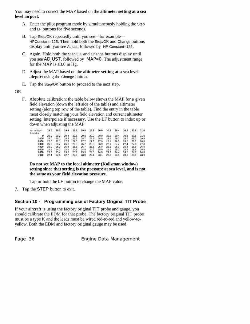
F. Absolute calibration: the table below shows the MAP for a given field elevation (down the left side of the table) and altimeter setting (along top row of the table). Find the entry in the table most closely matching your field elevation and current altimeter setting. Interpolate if necessary. Use the LF button to index up or down when adjusting the MAPAlt setting->field elev.
29.0 29.2 29.4 29.6 29.8 29.9 30.0 30.2 30.4 30.6 30.8 31.0
0 29.0 29.2 29.4 29.6 29.8 29.9 30.0 30.2 30.4 30.6 30.8 31.01000 28.0 28.2 28.4 28.5 28.7 28.8 28.9 29.1 29.3 29.5 29.7 29.92000 27.0 27.1 27.3 27.5 27.7 27.8 27.9 28.1 28.3 28.5 28.6 28.83000 26.0 26.2 26.3 26.5 26.7 26.8 26.9 27.1 27.2 27.4 27.6 27.84000 25.0 25.2 25.4 25.6 25.7 25.8 25.9 26.1 26.3 26.4 26.6 26.85000 24.1 24.3 24.5 24.6 24.8 24.9 25.0 25.1 25.3 25.5 25.6 25.86000 23.2 23.4 23.6 23.7 23.9 24.0 24.0 24.2 24.4 24.5 24.7 24.87000 22.4 22.5 22.7 22.8 23.0 23.1 23.1 23.3 23.5 23.6 23.8 23.9
Do not set MAP to the local altimeter (Kollsman window) setting since that setting is the pressure at sea level, and is not the same as your field elevation pressure.
Tap or hold the LF button to change the MAP value.
7. Tap the STEP button to exit.
Section 10 - Programming use of Factory Original TIT Probe
If your aircraft is using the factory original TIT probe and gauge, you should calibrate the EDM for that probe. The factory original TIT probe must be a type K and the leads must be wired red-to-red and yellow-to-yellow. Both the EDM and factory original gauge may be used
Page 36 Engine Data Management

concurrently. Due to the high input impedance of the EDM instrument, it will not affect the accuracy of the factory installed probe or gauge.
In normal cruise flight, record the difference between the factory installed TIT gauge and the EDM TIT reading.
TIT gauge ________ EDM ________.
If you haven’t already done so, start the pilot programming procedure, by simultaneously holding the STEP and LF buttons for five seconds. You will see the word PROGRAM for two seconds.
For Your Safe Flight Page 37
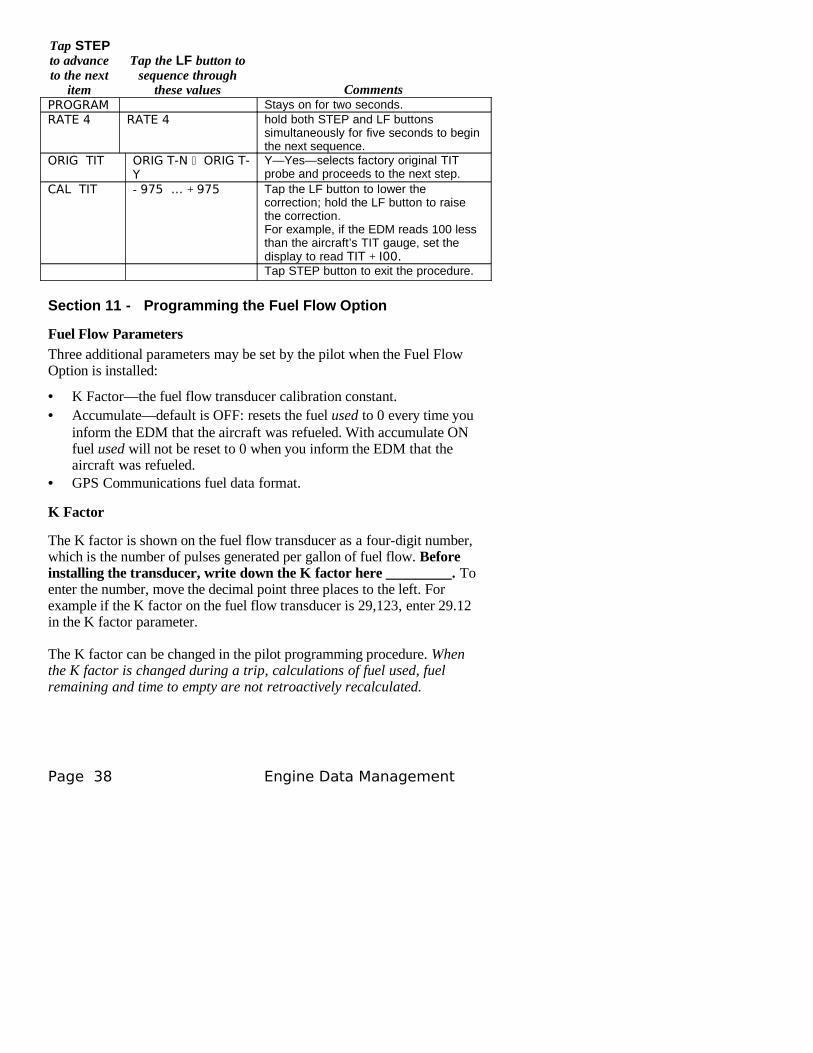
Tap STEP to advance to the next
item
Tap the LF button to sequence through
these values CommentsPROGRAM Stays on for two seconds.RATE 4 RATE 4 hold both STEP and LF buttons
simultaneously for five seconds to begin the next sequence.
ORIG TIT ORIG T-N ORIG T-Y
Y—Yes—selects factory original TIT probe and proceeds to the next step.
CAL TIT - 975 … + 975 Tap the LF button to lower the correction; hold the LF button to raise the correction.For example, if the EDM reads 100 less than the aircraft’s TIT gauge, set the display to read TIT + I00.Tap STEP button to exit the procedure.
Section 11 - Programming the Fuel Flow Option
Fuel Flow ParametersThree additional parameters may be set by the pilot when the Fuel Flow Option is installed:
• K Factor—the fuel flow transducer calibration constant.• Accumulate—default is OFF: resets the fuel used to 0 every time you
inform the EDM that the aircraft was refueled. With accumulate ON fuel used will not be reset to 0 when you inform the EDM that the aircraft was refueled.
• GPS Communications fuel data format.
K Factor
The K factor is shown on the fuel flow transducer as a four-digit number, which is the number of pulses generated per gallon of fuel flow. Before installing the transducer, write down the K factor here _________. To enter the number, move the decimal point three places to the left. For example if the K factor on the fuel flow transducer is 29,123, enter 29.12 in the K factor parameter.
The K factor can be changed in the pilot programming procedure. When the K factor is changed during a trip, calculations of fuel used, fuel remaining and time to empty are not retroactively recalculated.
Page 38 Engine Data Management
Fine Tuning the K Factor
The K factor shown on the fuel flow transducer does not take into account your aircraft’s particular installation. Fuel hose diameters and lengths, elbows, fittings and routing can cause the true K factor to be different from that shown on the fuel flow transducer.
You must use the following procedure to fine tune the K factor.
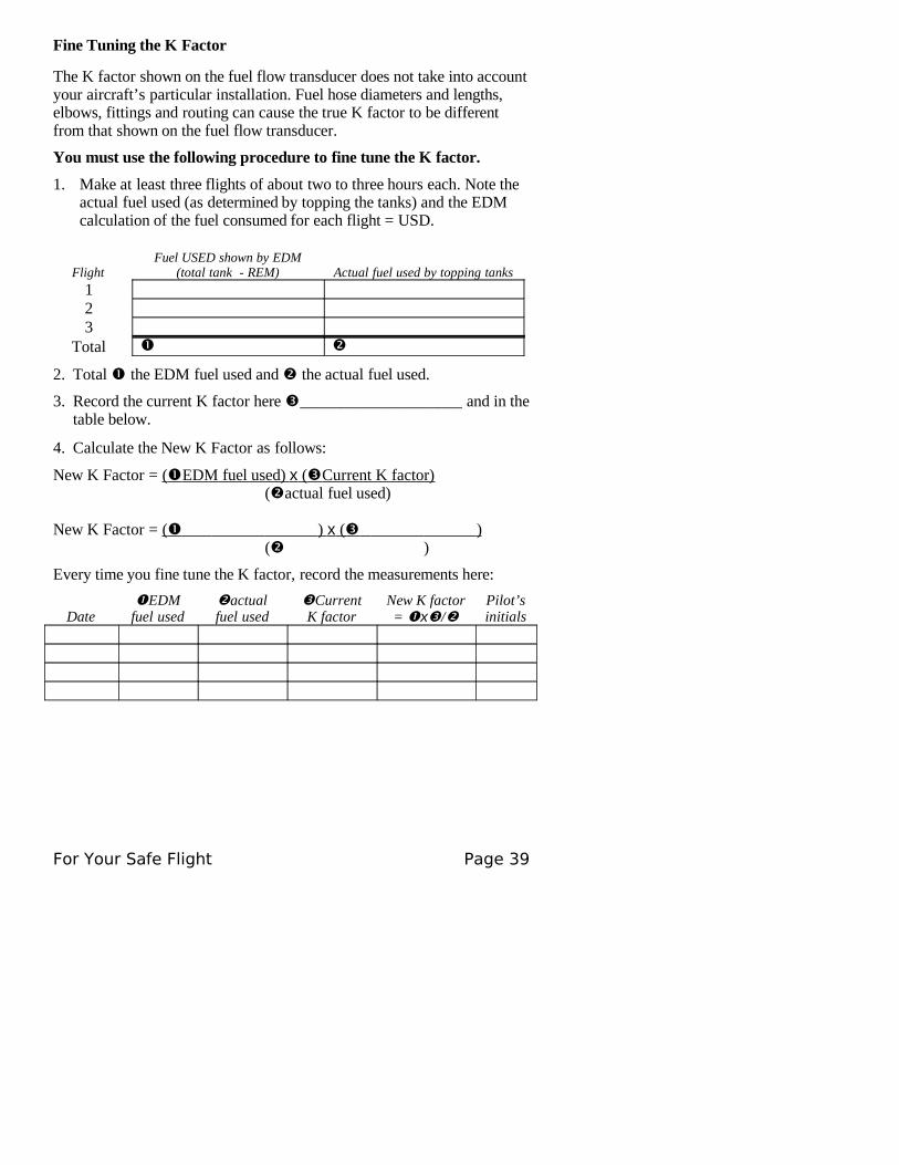
1. Make at least three flights of about two to three hours each. Note the actual fuel used (as determined by topping the tanks) and the EDM calculation of the fuel consumed for each flight = USD.
FlightFuel USED shown by EDM
(total tank - REM) Actual fuel used by topping tanks123
Total
2. Total the EDM fuel used and the actual fuel used.
3. Record the current K factor here ____________________ and in the table below.
4. Calculate the New K Factor as follows:
New K Factor = ( EDM fuel used) x ( Current K factor) (actual fuel used)
New K Factor = ( ) x ( ) ( )
Every time you fine tune the K factor, record the measurements here:
DateEDM
fuel usedactual fuel used
Current K factor
New K factor= x/
Pilot’s initials
For Your Safe Flight Page 39
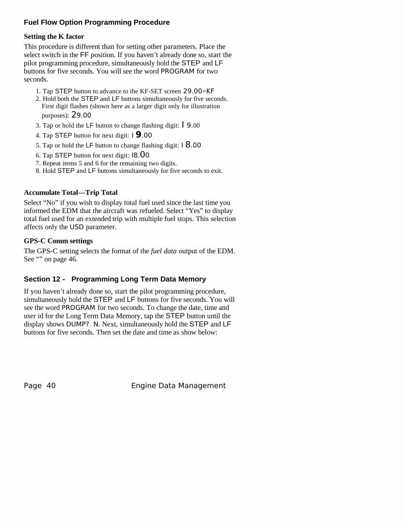
Fuel Flow Option Programming Procedure
Setting the K factor This procedure is different than for setting other parameters. Place the select switch in the FF position. If you haven’t already done so, start the pilot programming procedure, simultaneously hold the STEP and LF buttons for five seconds. You will see the word PROGRAM for two seconds.
1. Tap STEP button to advance to the KF-SET screen 29.00=KF2. Hold both the STEP and LF buttons simultaneously for five seconds.
First digit flashes (shown here as a larger digit only for illustration
purposes): 29.00
3. Tap or hold the LF button to change flashing digit: I 9.00
4. Tap STEP button for next digit: I 9.00
5. Tap or hold the LF button to change flashing digit: I 8.00
6. Tap STEP button for next digit: I8.007. Repeat items 5 and 6 for the remaining two digits.8. Hold STEP and LF buttons simultaneously for five seconds to exit.
Accumulate Total—Trip TotalSelect “No” if you wish to display total fuel used since the last time you informed the EDM that the aircraft was refueled. Select “Yes” to display total fuel used for an extended trip with multiple fuel stops. This selection affects only the USD parameter.
GPS-C Comm settings
The GPS-C setting selects the format of the fuel data output of the EDM. See “” on page 46.
Section 12 - Programming Long Term Data Memory
If you haven’t already done so, start the pilot programming procedure, simultaneously hold the STEP and LF buttons for five seconds. You will see the word PROGRAM for two seconds. To change the date, time and user id for the Long Term Data Memory, tap the STEP button until the display shows DUMP? N. Next, simultaneously hold the STEP and LF buttons for five seconds. Then set the date and time as show below:
Page 40 Engine Data Management
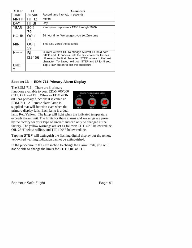
STEP LF CommentsTIME 2 500 Record time interval, in seconds
MNTH I I2 Month
DAY I 3I Day
YEAR 80 79
Year (note: represents 1980 through 2079)
HOUR OO 23
24 hour time. We suggest you set Zulu time
MIN OO 59
This also zeros the seconds
N----- N I23456
Current Aircraft ID. To change Aircraft ID, hold both STEP and LF buttons until the first character flashes. LF selects the first character. STEP moves to the next character. To Save, hold both STEP and LF for 5 sec.
END Y
Tap STEP button to exit the procedure.
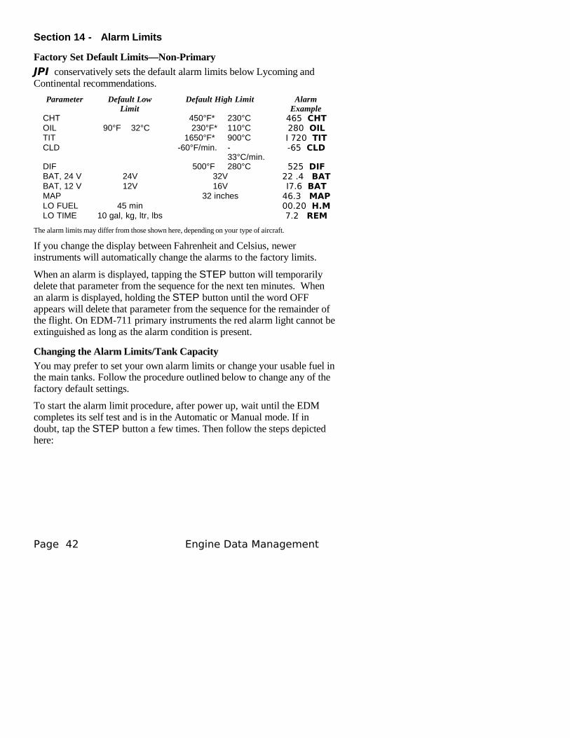
Section 13 - EDM-711 Primary Alarm Display
The EDM-711—There are 3 primary functions available to your EDM-700/800 CHT, OIL and TIT. When an EDM-700-800 has primary functions it is called an EDM-711. A Remote alarm lamp is supplied that will function even when the primary display fails. Each lamp is a dual lamp Red/Yellow. The lamp will light when the indicated temperature exceeds alarm limit. The limits for these alarms and warnings are preset by the factory for your type of aircraft and can only be changed at the factory. The yellow warnings are set as follows: CHT 45°F below redline, OIL 25°F below redline, and TIT 100°F below redline.
Tapping STEP will extinguish the flashing digital display but the remote yellow/red warning indication cannot be extinguished.
In the procedure in the next section to change the alarm limits, you will not be able to change the limits for CHT, OIL or TIT.
For Your Safe Flight Page 41
R/Y
460F 230F 1650F
Engine Temperature LimitCHT OIL TIT
R/Y R/Y R/Y
Section 14 - Alarm Limits
Factory Set Default Limits—Non-Primary
JPI conservatively sets the default alarm limits below Lycoming and Continental recommendations.
Parameter Default Low Limit
Default High Limit Alarm Example
CHT 450°F* 230°C 465 CHTOIL 90°F 32°C 230°F* 110°C 280 OILTIT 1650°F* 900°C I 720 TITCLD -60°F/min. -
33°C/min.-65 CLD
DIF 500°F 280°C 525 DIFBAT, 24 V 24V 32V 22 .4 BATBAT, 12 V 12V 16V I7.6 BATMAP 32 inches 46.3 MAPLO FUEL 45 min 00.20 H.MLO TIME 10 gal, kg, ltr, lbs 7.2 REM
The alarm limits may differ from those shown here, depending on your type of aircraft.
If you change the display between Fahrenheit and Celsius, newer instruments will automatically change the alarms to the factory limits.
When an alarm is displayed, tapping the STEP button will temporarily delete that parameter from the sequence for the next ten minutes. When an alarm is displayed, holding the STEP button until the word OFF appears will delete that parameter from the sequence for the remainder of the flight. On EDM-711 primary instruments the red alarm light cannot be extinguished as long as the alarm condition is present.
Changing the Alarm Limits/Tank Capacity
You may prefer to set your own alarm limits or change your usable fuel in the main tanks. Follow the procedure outlined below to change any of the factory default settings.
To start the alarm limit procedure, after power up, wait until the EDM completes its self test and is in the Automatic or Manual mode. If in doubt, tap the STEP button a few times. Then follow the steps depicted here:
Page 42 Engine Data Management
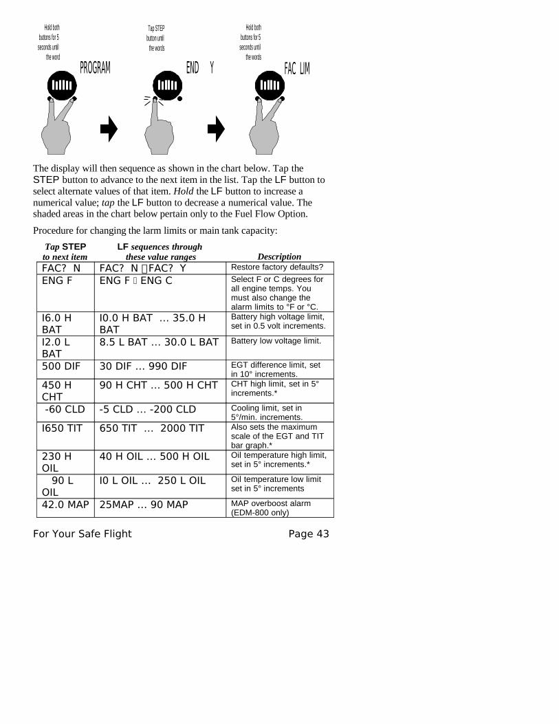
Hold bothbuttons for 5
seconds untilthe words
FAC LIM
Tap STEPbutton until
the words
END Y
Hold bothbuttons for 5
seconds untilthe word
PROGRAM
The display will then sequence as shown in the chart below. Tap the STEP button to advance to the next item in the list. Tap the LF button to select alternate values of that item. Hold the LF button to increase a numerical value; tap the LF button to decrease a numerical value. The shaded areas in the chart below pertain only to the Fuel Flow Option.
Procedure for changing the larm limits or main tank capacity:
Tap STEP to next item
LF sequences through these value ranges Description
FAC? N FAC? N FAC? Y Restore factory defaults?
ENG F ENG F ENG C Select F or C degrees for all engine temps. You must also change the alarm limits to °F or °C.
I6.0 H BAT
I0.0 H BAT … 35.0 H BAT
Battery high voltage limit, set in 0.5 volt increments.
I2.0 L BAT
8.5 L BAT … 30.0 L BAT Battery low voltage limit.
500 DIF 30 DIF … 990 DIF EGT difference limit, set in 10° increments.
450 H CHT
90 H CHT … 500 H CHT CHT high limit, set in 5° increments.*
-60 CLD -5 CLD … -200 CLD Cooling limit, set in 5°/min. increments.
I650 TIT 650 TIT … 2000 TIT Also sets the maximum scale of the EGT and TIT bar graph.*
230 H OIL
40 H OIL … 500 H OIL Oil temperature high limit, set in 5° increments.*
90 L OIL
I0 L OIL … 250 L OIL Oil temperature low limit set in 5° increments
42.0 MAP 25MAP … 90 MAP MAP overboost alarm (EDM-800 only)
For Your Safe Flight Page 43
FUEL GAL
FUEL GALFUEL KGSFUEL LTRFUEL LBS
Selects the units in all parameters where fuel quantity or fuel rate is displayed
MAIN=50 MAIN=0 … MAIN=999 Main tank capacity, in units selected
AUX? N AUX? N AUX ? Y Y—Yes—aircraft has auxiliary tanks
AUX=0 AUX=0 … AUX=250 Auxiliary tank capacity
MIN =45 MIN =0 … MIN =60 Alarm limit in minutes for low time in tanks
REM =I0 REM =0 … REM =200 Alarm limit for low fuel quantity in tanks, in units selected
CARB? CARB? N CARB? Y
Y—Yes—carbureted engine. Setting 1-3, 3 being high filter
RECRD? RECRD? Y RECRD? N
Long Term Memory.Y—only data recording. N—only real-time data output.
CYL=6 CYL=4 … CYL=I 2 (EDM-800 only) Set the number of cylinders. See page 45 for exceptions.
HP = I 80
HP=60 … HP=500 (EDM-800 only) Set the HP constant
I 4.90 = EC
I 2.00= EC… I6.00= EC
(EDM-800 only) Set the Engine Constant
END Y END N Y—Yes to exit; N—No to review list again
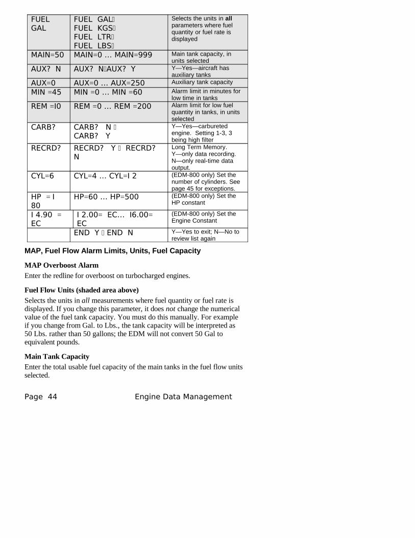
MAP, Fuel Flow Alarm Limits, Units, Fuel Capacity
MAP Overboost Alarm
Enter the redline for overboost on turbocharged engines.
Fuel Flow Units (shaded area above)
Selects the units in all measurements where fuel quantity or fuel rate is displayed. If you change this parameter, it does not change the numerical value of the fuel tank capacity. You must do this manually. For example if you change from Gal. to Lbs., the tank capacity will be interpreted as 50 Lbs. rather than 50 gallons; the EDM will not convert 50 Gal to equivalent pounds.
Main Tank CapacityEnter the total usable fuel capacity of the main tanks in the fuel flow units selected.
Page 44 Engine Data Management
If you do not have auxiliary tanks or tank tabs, answer “No.” If you answer “Yes,” you will be asked to input the capacity of the auxiliary tanks in the fuel flow units selected. If you have tank tabs and sometimes fill only to the tabs, set the auxiliary tank capacity to the difference between full tank capacity and tab capacity. The EDM does not differentiate fuel flow between the main and auxiliary tanks; it tracks only total fuel in the aircraft.
Low Time Alarm Limit
Select the value of the time remaining, in minutes, that triggers the alarm. Time remaining is calculated at the current fuel flow rate.
Low Fuel Alarm LimitSelect the value of the fuel remaining, in the selected fuel flow units, that triggers the alarm. Fuel remaining is calculated at the current fuel flow rate.
Carburetor?Different response filters are used depending on whether your engine is carbureted or fuel injected. The filter for a carbureted engine has a slower response time to reduce sudden fluctuations in readings. The higher the number the more filtering or less jumping around.
Number of Cylinders
This applies only to EDM-800. Set CYL = 4 or 6 depending on your engine. Exceptions:
• 4 cylinder engine with dual (all-in-one) magnetos set to CYL= 8.• 4 cylinder Lasar® ignition set to CYL=8.• 6 cylinder Lasar® ignition set to CYL=I2.
HP and EC (EDM-800 only)These adjustments set the parameters for the HP calculations in the EDM. Set the Rated HP for your particular aircraft. Set the HP Constant to 14.9 for normally aspirated or turbo normalized engines; set it to 13.75 for turbo boost engines. To set the EC, hold STEP and LF for five seconds. The first digit will flash. Use LF to change the digit, use STEP to advance to the next digit. Hold STEP and LF for five seconds to exit.
Initially Entering the Tank Capacity
To initialize or change the tank capacities, hold the STEP button while turning on the power to the EDM. The following program steps will be displayed:
For Your Safe Flight Page 45
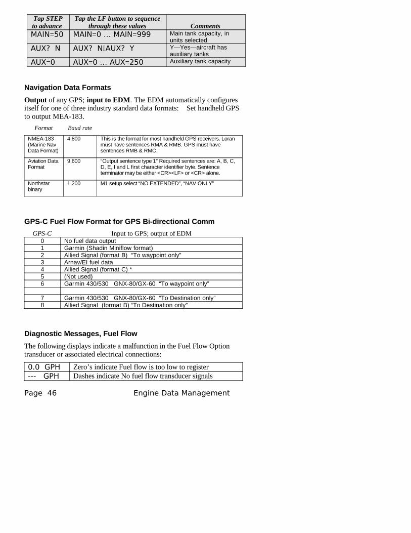
Tap STEP to advance
Tap the LF button to sequence through these values Comments
MAIN=50 MAIN=0 … MAIN=999 Main tank capacity, in units selected
AUX? N AUX? N AUX ? Y Y—Yes—aircraft has auxiliary tanks
AUX=0 AUX=0 … AUX=250 Auxiliary tank capacity
Navigation Data Formats
Output of any GPS; input to EDM. The EDM automatically configures itself for one of three industry standard data formats: Set handheld GPS to output MEA-183.
Format Baud rate
NMEA-183 (Marine Nav Data Format)
4,800 This is the format for most handheld GPS receivers. Loran must have sentences RMA & RMB. GPS must have sentences RMB & RMC.
Aviation Data Format
9,600 “Output sentence type 1” Required sentences are: A, B, C, D, E, I and L first character identifier byte. Sentence terminator may be either <CR><LF> or <CR> alone.
Northstar binary
1,200 M1 setup select “NO EXTENDED”, “NAV ONLY”
GPS-C Fuel Flow Format for GPS Bi-directional Comm
GPS-C Input to GPS; output of EDM0 No fuel data output1 Garmin (Shadin Miniflow format)2 Allied Signal (format B) “To waypoint only”3 Arnav/EI fuel data4 Allied Signal (format C) *5 (Not used)6 Garmin 430/530 GNX-80/GX-60 “To waypoint only”
7 Garmin 430/530 GNX-80/GX-60 “To Destination only”8 Allied Signal (format B) “To Destination only”
Diagnostic Messages, Fuel Flow
The following displays indicate a malfunction in the Fuel Flow Option transducer or associated electrical connections:
0.0 GPH Zero’s indicate Fuel flow is too low to register--- GPH Dashes indicate No fuel flow transducer signals
Page 46 Engine Data Management
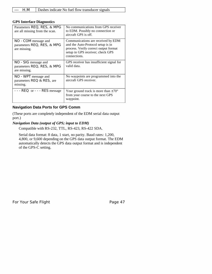
--- H.M Dashes indicate No fuel flow transducer signals
GPS Interface DiagnosticsParameters REQ, RES, & MPG are all missing from the scan.
No communications from GPS receiver to EDM. Possibly no connection or aircraft GPS is off.
NO - COM message and parameters REQ, RES, & MPG are missing.
Communications are received by EDM and the Auto-Protocol setup is in process. Verify correct output format setup in GPS receiver; check GPS connections.
NO - SIG message and parameters REQ, RES, & MPG are missing.
GPS receiver has insufficient signal for valid data.
NO - WPT message and parameters REQ & RES, are missing.
No waypoints are programmed into the aircraft GPS receiver.
- - - REQ or - - - RES message Your ground track is more than ±70° from your course to the next GPS waypoint.
Navigation Data Ports for GPS Comm
(These ports are completely independent of the EDM serial data output port.)
Navigation Data (output of GPS; input to EDM)Compatible with RS-232, TTL, RS-423, RS-422 SDA.
Serial data format: 8 data, 1 start, no parity. Baud rates: 1,200, 4,800, or 9,600 depending on the GPS data output format. The EDM automatically detects the GPS data output format and is independent of the GPS-C setting.
For Your Safe Flight Page 47
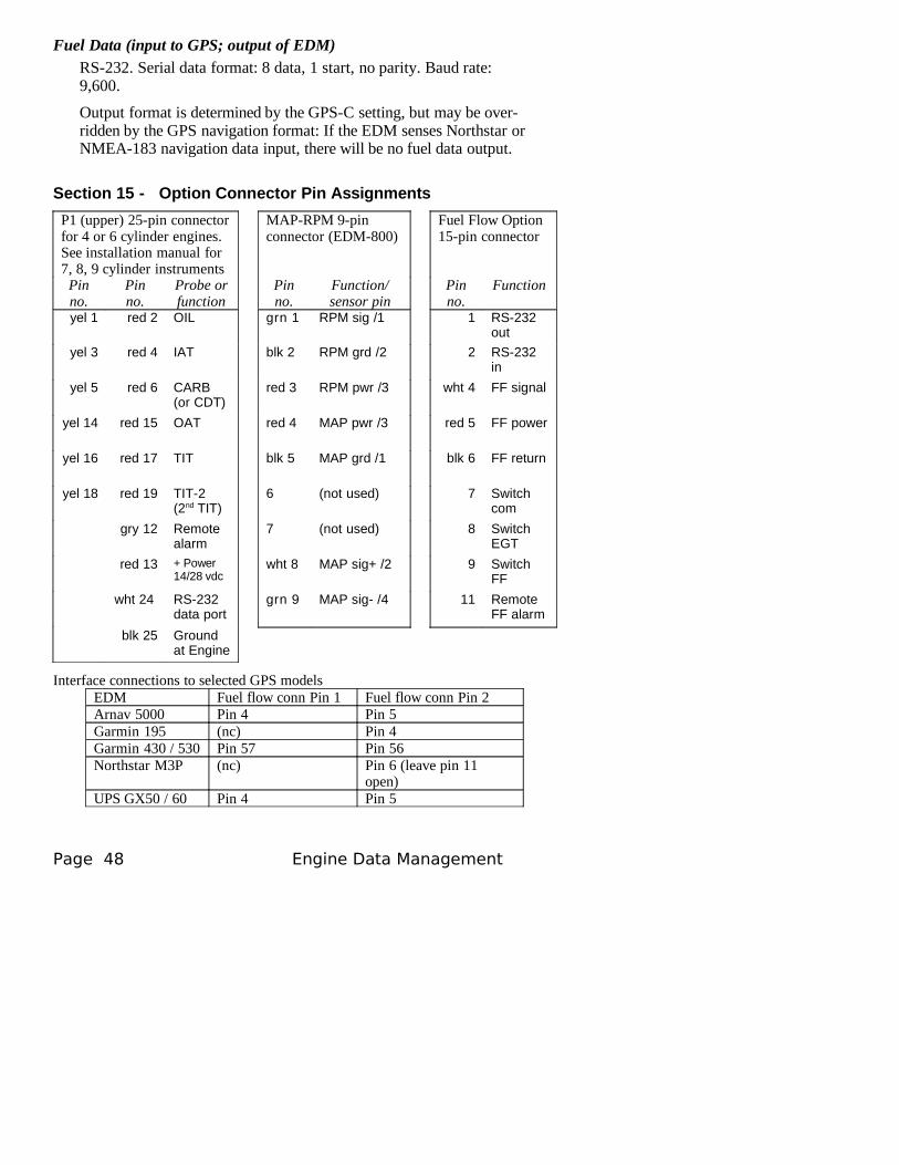
Fuel Data (input to GPS; output of EDM)RS-232. Serial data format: 8 data, 1 start, no parity. Baud rate: 9,600.
Output format is determined by the GPS-C setting, but may be over-ridden by the GPS navigation format: If the EDM senses Northstar or NMEA-183 navigation data input, there will be no fuel data output.
Section 15 - Option Connector Pin Assignments
P1 (upper) 25-pin connector for 4 or 6 cylinder engines. See installation manual for 7, 8, 9 cylinder instruments
MAP-RPM 9-pin connector (EDM-800)
Fuel Flow Option 15-pin connector
Pin no.
Pinno.
Probe or function
Pin no.
Function/ sensor pin
Pin no.
Function
yel 1 red 2 OIL grn 1 RPM sig /1 1 RS-232 out
yel 3 red 4 IAT blk 2 RPM grd /2 2 RS-232 in
yel 5 red 6 CARB(or CDT)
red 3 RPM pwr /3 wht 4 FF signal
yel 14 red 15 OAT red 4 MAP pwr /3 red 5 FF power
yel 16 red 17 TIT blk 5 MAP grd /1 blk 6 FF return
yel 18 red 19 TIT-2(2nd TIT)
6 (not used) 7 Switch com
gry 12 Remote alarm
7 (not used) 8 Switch EGT
red 13 + Power14/28 vdc
wht 8 MAP sig+ /2 9 Switch FF
wht 24 RS-232 data port
grn 9 MAP sig- /4 11 Remote FF alarm
blk 25 Ground at Engine
Interface connections to selected GPS modelsEDM Fuel flow conn Pin 1 Fuel flow conn Pin 2Arnav 5000 Pin 4 Pin 5Garmin 195 (nc) Pin 4Garmin 430 / 530 Pin 57 Pin 56Northstar M3P (nc) Pin 6 (leave pin 11
open)UPS GX50 / 60 Pin 4 Pin 5
Page 48 Engine Data Management
Section 16 - Reference Reading
You may wish to know more about the effect of engine operations on EGT and CHT. The reading list below provides general overviews as well as original references on topics that may be of interest.
General Overview
These references are readily available to pilots and provide a readable source of general technical information.
• Teledyne Continental Motors, Engine Operation for Pilots, from the FAA Accident Prevention Program, FAA-P-8740-13.
• Editors of Light Plane Maintenance Magazine, EGT Systems, Belvoir Publications Inc., Greenwich, CT 06836. 1989.
• Lycoming Flyer Issue 53 dated January 93.
Technical Reviews and Original References
For those pilots who have engineering backgrounds, the references listed below present the original research on the combustion process and represent the source documents for those with technical interests.
• A. Hundere, “Autogas for Avgas,” AOPA Pilot, October, 1969.
• A. Hundere and J. Bert, “Pre-ignition and Its Deleterious Effects in Aircraft Engines,” SAE Quarterly Transactions, Vol. 2, No. 4, pages 547-562, October 1948.
Section 17 - Technical Support
JPI offers both e-mail ([email protected]) and telephone technical support. Have your model and serial number ready when you call. Call JPI for a return authorization number RMA before returning any equipment.
J.P. INSTRUMENTS Inc.3185 B AirwayCosta Mesa, CA 92626
800 345-4574 714 557 3805Fax 714-557-9840www.jpinstruments.com and www.jpitech.com
For Your Safe Flight Page 49
Limited Warranty
J.P. Instruments Inc. (JPI) warrants all parts in your new EDM to be free from defects in material and workmanship under normal use. Our obligation under this warranty is limited to repair or exchange of any defective part of this unit if the part is returned, shipping prepaid, within three years for electronics and one year for probes from the date of original purchase. Installation labor is the responsibility of the aircraft owner. Homebuilt aircraft warranty starts when the aircraft is certified for flight. Replacement parts carry a warranty for the balance of the warranty period.
Under this warranty, JPI is not responsible for any service charges, including removal, installation, nor any other consequential damages. JPI incurs no obligation under this warranty unless a Warranty Registration Certificate describing the warranted product has been completed and mailed to JPI with all information requested.
This warranty is void on any product which has been subject to misuse, accident, damage caused by negligence, damage in transit, handling or modification which, in the opinion of JPI, has altered or repaired the product in any way that effects the reliability or detracts from the performance of the product, or any product whereon the serial number has been altered, defaced, effaced or destroyed.
This warranty is in lieu of all other warranties expressed or implied and other obligations of liability on JPI’s part, and it neither assumes nor authorizes any other person to assume for JPI any other liability in connection with the sale of JPI products.
To initiate this warranty, the aircraft owner must submit a completed Data Logging Worksheet to JPI. Upon receiving a completed worksheet, JPI will initiate the warranty from the date of original purchase. Any replacement parts carry a warranty that extends for the balance of the period of the original warranty. For homebuilt aircraft the warranty starts when the aircraft is certificated for flight and noted on the warranty card.
Page 50 Engine Data Management
Index
A
Accumulate.................................34, 40Accumulate...........................................
total..............................................27Adding fuel.......................................27Alarm limits..........................................
factory defaults.............................42Alarms...............................................24
resetting.......................................24ALL...................................................34ALL.......................................................
select switch.................................26Allied Signal.....................................46Arnav.................................................46Automatic indexing mode...................7Automatic mode................................11AUX............................................44, 46Auxiliary tanks..................................44Avgas................................................25Aviation data format.........................46B
Bar graph..............................................column resolution..........................6EGT...............................................6
Baud rate...........................................47Buttons..................................................
front panel......................................8C
CAL ERR.........................................11Calibration............................................
internal self test...........................11K-factor........................................38
CARB?..............................................44Carburetor.........................................45Carburetor.............................................
temperature............................10, 29Celsius..................................................
display indicator.............................5engine temperatures.....................43
Changing alarm limits.......................42CHT......................................................
missing segment.............................6probe..............................................2too high or too low.......................24
Climb................................................18Combustion.............................2, 25, 49Compression.................................2, 23
high..............................................25low...............................................22
Compressor discharge temperature, CDT.......................................10, 29
Cowling, obstruction.........................23Cruise................................................19Cylinder numbers................................5D
Data.......................................................ports, GPS....................................47
Descent..............................................19Detonation.........................................24Diagnosing engine problems21, 36, 38,
42Diagnostic.............................................
fuel flow messages.......................46self test.........................................11
DIF........................................10, 29, 43Dimming, display................................7Display................................................4
analog.............................................4digital.............................................6
Dot index.............................................6Download..........................................31E
Economy, best.....................................3EDM-711..........................................41EGT.......................................................
alarms..........................................24loss...............................................22resolution, display........................33select switch.................................26too high........................................22too low.........................................23
Electronics International...................46Engine...................................................
diagnosis chart.............................22run-up...........................................18
Enunciator, alarm..............................24F
Fahrenheit.............................................display indicator.............................5
Failure to pre-lean.............................20FF, select switch ..............................26Fill options........................................27FILL? N.............................................26Flash drive........................................31Flashing display..............13, 16, 24, 25Flat EGT response............................24Fuel.......................................................
injectors, clogged...............2, 18, 23
For Your Safe Flight Page 51
Octane..........................................24pump............................................24tank capacity..........................26, 44
Fuel flow...............................................alarm limits..................................44units.............................................44
G
GAMI..............................12, 13, 15, 16Gasket probe.....................................21Gasket, manifold...............................24GPH..................................................29GPS.......................................................
comm settings..............................40constant........................................34interface diagnostics....................47
H
H.S....................................................29Hastaloy............................................16HBAT................................................43HCHT................................................43HOIL.................................................43Holding a button.................................8Horsepower...........................................
constant setting............................35I
Ice, carburetor or induction...............23Ignition..............................................24Ignition..................................................
timing...........................................22Include parameters............................11Indexing................................................
sequence.......................................29Induction...........................................23
air temperature, IAT..............10, 29Intake valve.......................................22K
K-factor.................................................changing.................................34, 40determing.....................................39
KPH..................................................29L
Leak......................................................manifold.......................................24
Leak, manifold..................................18Lean of Peak......................................15Lean of Peak Leaning........................15Leanest cylinder................................13LeanFind...............................................
button.............................................8description.....................................7mode............................................12
procedure.....................................12Leaning...............................................2Leaning.................................................
pre-leaning...................................14too quickly...................................20
Long Term Memory Option..................operation......................................30
Low fuel alarm..................................45LPH...................................................29M
Magneto check..................................18MAIN..........................................44, 46Manifold Air Pressure (MAP)..............
calibration....................................35Manual indexing mode.......................7Manual mode....................................12MAP......................................................
calibration....................................34Mark..................................................30Memory box......................................31Miles per gallon................................29Misapplications.................................20Missing.................................................
segment..........................................6Mixture...............................................2Modes...........................................7, 11MPG, MPK, MPL, MPP...................29MS Excel...........................................30N
Navigation data formats....................46NMEA-183........................................46NO COM...........................................47NO SIG.............................................47NO WPT...........................................47Normal engine limits........................21Normalize view...................................5Northstar binary format.....................46O
OAT......................................................calibration....................................33F or C...........................................33
OFF.........................................8, 25, 42Off-scale EGT bars...........................20OIL..............................................10, 29OPEN PRB........................................11Operation..............................................
fuel flow option............................26temperature scanner.......................4
Option connector...............................48Outside air temperature....................10P
Page 52 Engine Data Management

Parameter indexing.......................9, 28Peak EGT..........................................14PEAK EGT.................................13, 15Percentage view..................................4Pilot programming............................33
data recording..............................40fuel flow option............................38
Power, best..........................................3PPH...................................................29Pre-ignition.................................23, 25Priority, alarm...................................25R
Rate.......................................................fuel flow.......................................28indexing.......................................38
Real-time...........................................44RECRD?............................................44Reference reading.............................49REM..................................................29REQ..................................................29RES...................................................29Reset.....................................................
fuel used.......................................27Rich of Peak......................................12RS-232..............................................47S
Select switch.....................................26Self-test.............................................11Setting the K factor...........................40Shadin Miniflow...............................46Shock cooling..................10, 12, 19, 21Spark plug.............................................
fouling................................5, 18, 22
Startup...................................................diagnostics...................................11fuel...............................................26
STEP button........................................8T
Take-off.............................................18Tank capacity........................................
entering at power up....................45Tanks, fuel............................................
tabs...............................................26Tapping a button.................................8Technical support..............................49TIT....................................................10
factory original probe...................36missing segment.............................5
Toggle, N, P........................................5Transducer, fuel flow........................28Turbocharged Engines.......................16U
Uniform, CHT, EGT not...................23USB.......................................................
port...............................................32USD..................................................29V
Valve.....................................................stuck.............................................22
Vapor................................................24View......................................................
change diagram..............................8Voltage........................................10, 29W
Warranty...........................................50
For Your Safe Flight Page 53
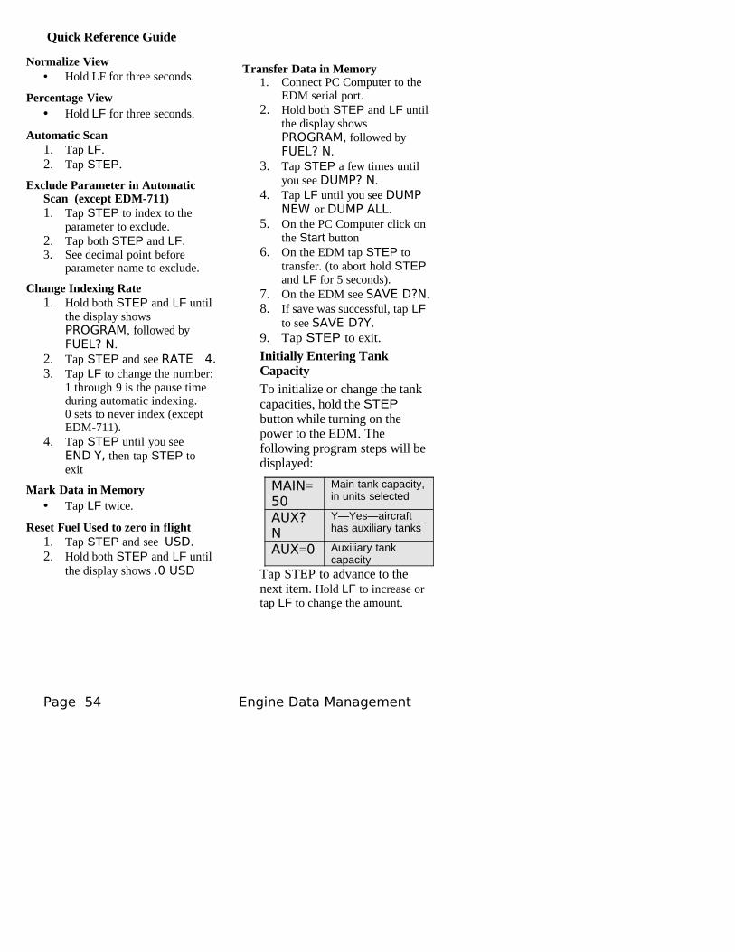
Quick Reference Guide
Normalize View• Hold LF for three seconds.
Percentage View• Hold LF for three seconds.
Automatic Scan1. Tap LF.2. Tap STEP.
Exclude Parameter in Automatic Scan (except EDM-711)1. Tap STEP to index to the
parameter to exclude.2. Tap both STEP and LF.3. See decimal point before
parameter name to exclude.
Change Indexing Rate1. Hold both STEP and LF until
the display shows PROGRAM, followed by FUEL? N.
2. Tap STEP and see RATE 4.3. Tap LF to change the number:
1 through 9 is the pause time during automatic indexing.0 sets to never index (except EDM-711).
4. Tap STEP until you see END Y, then tap STEP to exit
Mark Data in Memory• Tap LF twice.
Reset Fuel Used to zero in flight1. Tap STEP and see USD.2. Hold both STEP and LF until
the display shows .0 USD
Transfer Data in Memory1. Connect PC Computer to the
EDM serial port.2. Hold both STEP and LF until
the display shows PROGRAM, followed by FUEL? N.
3. Tap STEP a few times until you see DUMP? N.
4. Tap LF until you see DUMP NEW or DUMP ALL.
5. On the PC Computer click on the Start button
6. On the EDM tap STEP to transfer. (to abort hold STEP and LF for 5 seconds).
7. On the EDM see SAVE D?N.8. If save was successful, tap LF
to see SAVE D?Y.9. Tap STEP to exit.Initially Entering Tank CapacityTo initialize or change the tank capacities, hold the STEP button while turning on the power to the EDM. The following program steps will be displayed:
MAIN=50
Main tank capacity, in units selected
AUX? N
Y—Yes—aircraft has auxiliary tanks
AUX=0 Auxiliary tank capacity
Tap STEP to advance to the next item. Hold LF to increase or tap LF to change the amount.
Page 54 Engine Data Management
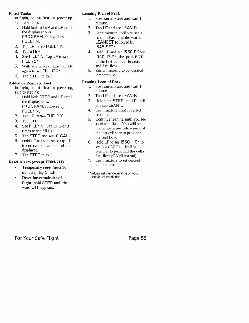
Filled TanksIn flight, do this first (on power up, skip to step 4):1. Hold both STEP and LF until
the display shows PROGRAM, followed by FUEL? N.
2. Tap LF to see FUEL? Y.3. Tap STEP4. See FILL? N. Tap LF to see
FILL 75*5. With aux tanks or tabs, tap LF
again to see FILL I20*6. Tap STEP to exit.
Added or Removed FuelIn flight, do this first (on power up, skip to step 4):1. Hold both STEP and LF until
the display shows PROGRAM, followed by FUEL? N.
2. Tap LF to see FUEL? Y.3. Tap STEP.4. See FILL? N. Tap LF 2 or 3
times to see FILL+.5. Tap STEP and see .0 GAL.6. Hold LF to increase or tap LF
to decrease the amount of fuel displayed.
7. Tap STEP to exit.
Reset Alarm (except EDM-711)• Temporary reset (next 10
minutes): tap STEP.• Reset for remainder of
flight: hold STEP until the word OFF appears.
Leaning Rich of Peak1. Pre-lean mixture and wait 1
minute.2. Tap LF and see LEAN R.3. Lean mixture until you see a
column flash and the words LEANEST followed byI545 SET*
4. Hold LF and see I560 PK*or I560 I3.5*, the peak EGT of the first cylinder to peak and fuel flow.
5. Enrich mixture to set desired temperature.
Leaning Lean of Peak1. Pre-lean mixture and wait 1
minute.2. Tap LF and see LEAN R.3. Hold both STEP and LF until
you see LEAN L4. Lean mixture until inverted
columns.5. Continue leaning until you see
a column flash. You will see the temperature below peak of the last cylinder to peak and the fuel flow.
6. Hold LF to see I560 I.0* to see peak EGT of the first cylinder to peak and the delta fuel flow (GAMI spread).
7. Lean mixture to set desired temperature.
* Values will vary depending on your individual installation.
For Your Safe Flight Page 55


![1728EX+ : Programming Guide - safe-tech · 02 ... Streamline section Streamline Streamline section Streamline section ... 1728EX+ : Programming Guide Keywords [English] Created Date:](https://img.pdfslide.net/doc/110x75/5b84d6a77f8b9aec488d14a4/1728ex-programming-guide-safe-02-streamline-section-streamline-streamline.jpg)