Embed Size (px)
Citation preview

8/7/2019 Pin type clamping
http://slidepdf.com/reader/full/pin-type-clamping 1/6
Afzeri International Islamic University Malaysia
A.G. E SutjiptoInternational Islamic University Malaysia
Riza Muhida International Islamic University Malaysia
Atiah A.S
International Islamic University Malaysia
AbstractCurrent machining shop floors, which are
characterized by large variety of products in small
batch sizes, require dynamic access and real-time
monitoring capabilities that are responsive and
adaptive to the rapid changes of production capability.
This paper proposes an emergence technique for web
based manufacturing using CNC milling machine
which uses Specialy developed holding attachment forremote machining. The proposed system can be
applied for large variety of products in small batch
sizes which requires dynamic access and real-time
monitoring capabilities The web technologies have
been employed in developing manufacturing systems
which is connected to server and client for remote
operation and monitoring. The objective of this
research is to develop an appropriate tool and
methodology with open architecture for real-time
monitoring and remote operation of networked CNC
machines. A prototype named Setup Free Machining
(Integrated CNC Milling, Reconfigurable Pin type
fixture and Internet communication) is designed for
this purpose. A new enabling technology to bringtraditional CNC machine tools on-line with combined
operation and monitoring is also presented. Issues such
as architecture design, methodology development, and
prototype implementation are addressed through a
special developed material holding attachment. It is
expected that the developed technology can be readily
applied to real shop floor environments for fully
operated remote machining with increased
responsiveness.
KeywordsWeb-based manufacturing; Remote manufacturing ;
CNC machining; Java 3D
1. Introduction
Many remote manufacturing system allow different
user at different remote location to have their designs
manufactured at remote location by manufacturing
equipments. Various Web-based manufacturing
systems have been developed in the past decade for
supporting activities in deferent life-cycle phases of
product development, including marketing, design,
process planning, production, distribution, service, etc.,
and associating these distributed product development
life-cycle activities into a globally integrated
environment using Web technologies[1]. Many product
development software tools, such as CAD systems,
CAM systems, database management systems,
knowledge-based intelligent systems, etc., at different
locations have also been integrated through Web
technologies in these Web-based manufacturing.
Although many Web-based manufacturing systemshave been developed, most of these systems were
implemented as results of research or prototypes in
industry. Compared with the computer-based systems,
such as Computer Aided Design (CAD) systems,
Computer Aided Manufacturing (CAM) systems,
manufacturing modeling and simulation systems, etc.,
the importance and usefulness of Web-based
manufacturing systems for improving product of
manufacturing industry in real remote operation have
not been widely recognized and demonstrated. Many
problems are found within a system and need to be
solved for new improved the Web-based manufacturing
systems.
Despite all the accomplishments, the available systemsare either for off-line simulation or for monitoring only.
Advanced and distributed shop floor monitoring and
remote CNC control remain impractical as web-based
applications due to the real-time constraints and lack of
equipments. To facilitate a viable web-based
environment, application servers will engage users in a
3D graphical interaction. Remote users need active and
visual supports to coordinate their efforts in a
distributed environment. There are concerns in
reducing network traffic and increasing system. Today,
shop floor engineers and machine operators still have
to meet and respond the challenges for producing
highly complex products, especially in very small
batches. To be practical, a web-based monitoring andremote operation system should also be efficient andadaptive. This paper presents a new approach for fully
remote operated CNC Milling machine using Setup
Free attachment for auto loading of workpiece and Java
3D tools remote operation and monitoring.
Manufacturing of the parts completely in all surfaces
can be done for several processes continuously without
performing setup and attendance of technician for
product evaluation and work piece setup can also be
avoided.
Remote Manufacturing and Monitoring of CNC Milling Machine
With Integrated Setup Free through Web based Virtual 3D Environment
8/7/2019 Pin type clamping
http://slidepdf.com/reader/full/pin-type-clamping 2/6
2. Literature Review
Many Web-based manufacturing systems allow
different users at different locations to have their
designs manufactured at remote locations by expensivemanufacturing equipment such as CNC centers, robots,
and rapid prototyping machines. Several researches
concerning to utilization of web technology has been
investigated as listed bellow. In the CyberCut system[2], designers can use Web-browsers to design
components, send the process plans to a remote
controller, and execute the process plans on a three-
axis milling machine. However the system can not be
applied for complex geometry of component where
intensive manufacturing evaluation and changing the
setups is necessary. Web-based Rapid Prototyping
(RP) system called TeleRP for remote part submitting,queuing, and monitoring [3]. In this system, selection
of a valid and feasible rapid prototyping manufacturing
site registered in the RP tele-manufacturing Web
server depends mainly on two factors: site
manufacturing capability and delivery time constraints
concerning all the queues inside the site. Accuracy andvariety of material could be used for RP still lower
than milling process capability. An Internet-based
controlling of robotic system presented an experience
toward building for tele-operation shows the current
capability of networking system [4][5]. The system has
a standard network protocol and an interactive human
machine interface. Using a Web-browser, a remote
operator can control the mobile robot to navigate in the
laboratory with visual feedback and a simulated
environment map via the Internet. Many research has
been conducted for remote operation of manufacturing
equipments. Special case for machining process using
milling machine, part manufacturing still not possible
to be operated fully from remote for completeoperation. Attendance of operator is necessary for
setup of workpiece for every process.
3.The Current Connection Situation
The current state of technology for linking CNC
machine tools to the Internet is not very state-of-the-
art. Look at the desktop PC or laptop are available to
make it faster, simpler to use or more powerful.
Operating systems that come out of Microsoft on a
semi-regular basis are constantly adding more power to
the laptop or desktop PC. Contrast this situation with
that of CNC machine tools. Although the control units
are gaining more power and capabilities, their
weakness lies in connectivity to the outside world [6].
Several machine interface was designed to plug into
any network connection anywhere in the plant. If
machines had to be moved, the user could simply
relocate a network cable and plug it into the nearest
available network jack, quickly putting the machine
back online. NC part programs that are developed in
one facility can be downloaded directly to the CNC (or
to its Web server), even if that CNC is halfway around
the world. This is a nice feature for big manufacturers
who concentrate their CAD/CAM work in one location
and their manufacturing in another.
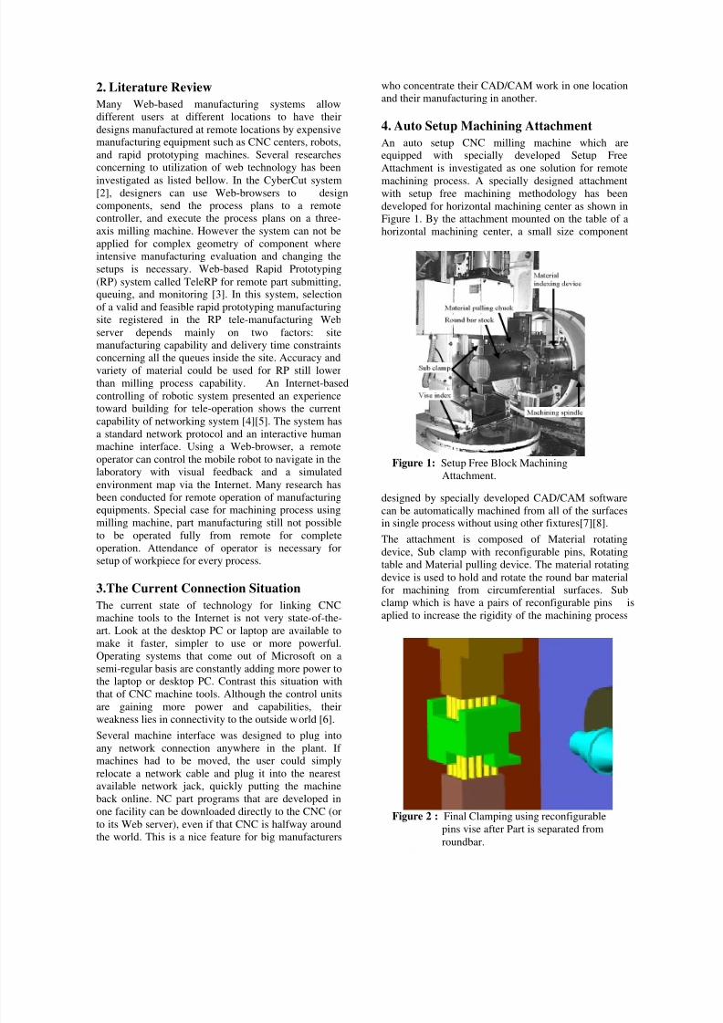
4. Auto Setup Machining Attachment
An auto setup CNC milling machine which areequipped with specially developed Setup Free
Attachment is investigated as one solution for remote
machining process. A specially designed attachmentwith setup free machining methodology has been
developed for horizontal machining center as shown in
Figure 1. By the attachment mounted on the table of a
horizontal machining center, a small size component
designed by specially developed CAD/CAM software
can be automatically machined from all of the surfacesin single process without using other fixtures[7][8].
The attachment is composed of Material rotatingdevice, Sub clamp with reconfigurable pins, Rotating
table and Material pulling device. The material rotating
device is used to hold and rotate the round bar material
for machining from circumferential surfaces. Sub
clamp which is have a pairs of reconfigurable pins is
aplied to increase the rigidity of the machining process
Figure 1: Setup Free Block Machining
Attachment.
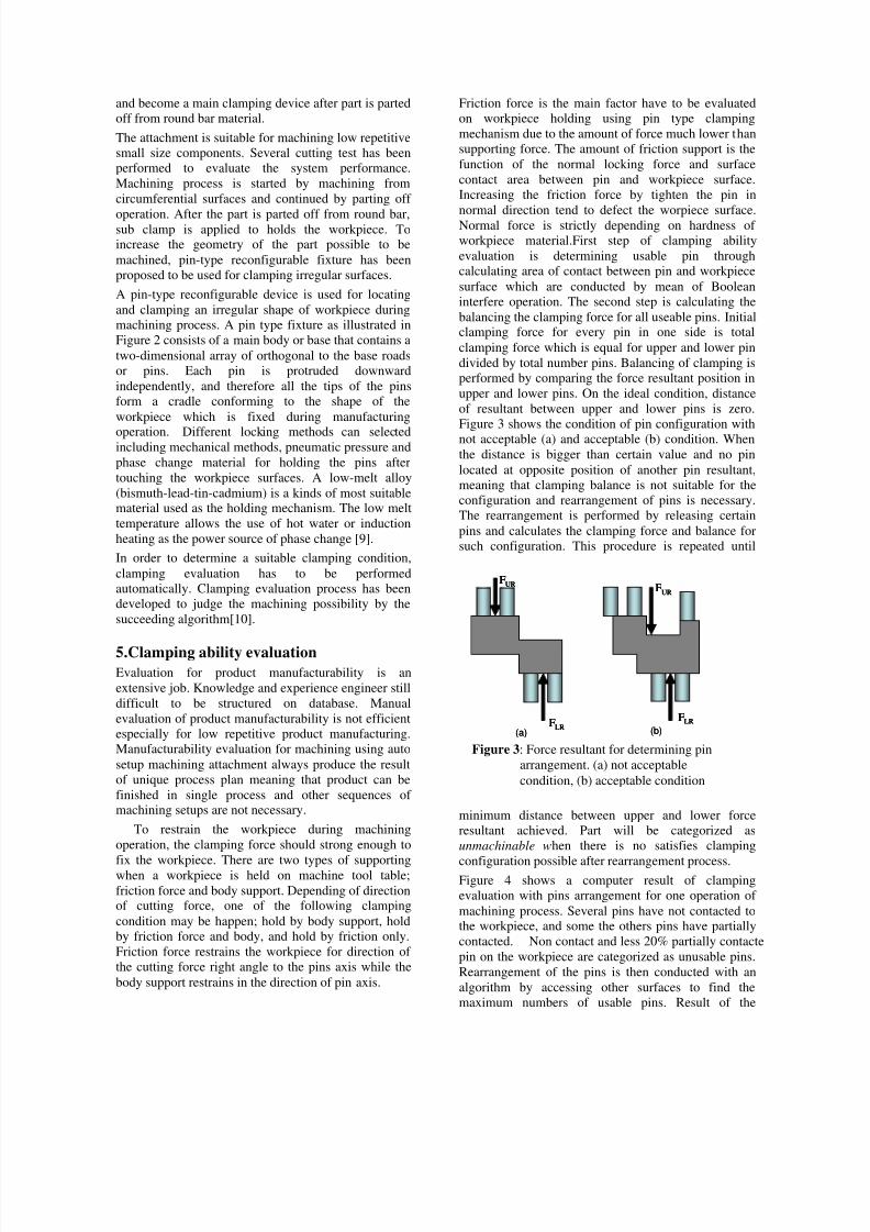
Figure 2 : Final Clamping using reconfigurable
pins vise after Part is separated from
roundbar.
8/7/2019 Pin type clamping
http://slidepdf.com/reader/full/pin-type-clamping 3/6
and become a main clamping device after part is parted
off from round bar material.
The attachment is suitable for machining low repetitive
small size components. Several cutting test has been
performed to evaluate the system performance.
Machining process is started by machining from
circumferential surfaces and continued by parting off
operation. After the part is parted off from round bar,sub clamp is applied to holds the workpiece. Toincrease the geometry of the part possible to be
machined, pin-type reconfigurable fixture has been
proposed to be used for clamping irregular surfaces.
A pin-type reconfigurable device is used for locating
and clamping an irregular shape of workpiece during
machining process. A pin type fixture as illustrated in
Figure 2 consists of a main body or base that contains a
two-dimensional array of orthogonal to the base roads
or pins. Each pin is protruded downward
independently, and therefore all the tips of the pins
form a cradle conforming to the shape of the
workpiece which is fixed during manufacturing
operation. Different locking methods can selectedincluding mechanical methods, pneumatic pressure and
phase change material for holding the pins after
touching the workpiece surfaces. A low-melt alloy
(bismuth-lead-tin-cadmium) is a kinds of most suitablematerial used as the holding mechanism. The low melt
temperature allows the use of hot water or induction
heating as the power source of phase change [9].
In order to determine a suitable clamping condition,
clamping evaluation has to be performed
automatically. Clamping evaluation process has been
developed to judge the machining possibility by the
succeeding algorithm[10].
5.Clamping ability evaluation
Evaluation for product manufacturability is an
extensive job. Knowledge and experience engineer still
difficult to be structured on database. Manual
evaluation of product manufacturability is not efficient
especially for low repetitive product manufacturing.
Manufacturability evaluation for machining using auto
setup machining attachment always produce the result
of unique process plan meaning that product can be
finished in single process and other sequences of machining setups are not necessary.
To restrain the workpiece during machining
operation, the clamping force should strong enough to
fix the workpiece. There are two types of supportingwhen a workpiece is held on machine tool table;
friction force and body support. Depending of directionof cutting force, one of the following clamping
condition may be happen; hold by body support, hold
by friction force and body, and hold by friction only.
Friction force restrains the workpiece for direction of
the cutting force right angle to the pins axis while the
body support restrains in the direction of pin axis.
Friction force is the main factor have to be evaluated
on workpiece holding using pin type clamping
mechanism due to the amount of force much lower than
supporting force. The amount of friction support is the
function of the normal locking force and surface
contact area between pin and workpiece surface.
Increasing the friction force by tighten the pin in
normal direction tend to defect the worpiece surface.Normal force is strictly depending on hardness of
workpiece material.First step of clamping ability
evaluation is determining usable pin through
calculating area of contact between pin and workpiece
surface which are conducted by mean of Boolean
interfere operation. The second step is calculating the
balancing the clamping force for all useable pins. Initialclamping force for every pin in one side is total
clamping force which is equal for upper and lower pin
divided by total number pins. Balancing of clamping is
performed by comparing the force resultant position in
upper and lower pins. On the ideal condition, distance
of resultant between upper and lower pins is zero.
Figure 3 shows the condition of pin configuration with
not acceptable (a) and acceptable (b) condition. When
the distance is bigger than certain value and no pin
located at opposite position of another pin resultant,
meaning that clamping balance is not suitable for the
configuration and rearrangement of pins is necessary.
The rearrangement is performed by releasing certain
pins and calculates the clamping force and balance for
such configuration. This procedure is repeated until
minimum distance between upper and lower force
resultant achieved. Part will be categorized as
unmachinable when there is no satisfies clamping
configuration possible after rearrangement process.Figure 4 shows a computer result of clamping
evaluation with pins arrangement for one operation of
machining process. Several pins have not contacted tothe workpiece, and some the others pins have partially
contacted. Non contact and less 20% partially contacte
pin on the workpiece are categorized as unusable pins.
Rearrangement of the pins is then conducted with an
algorithm by accessing other surfaces to find the
maximum numbers of usable pins. Result of the
FLR
FUR
FLR
FUR
(a) (b)
FLR
FUR
FLR
FUR
FLR
FUR
FLR
FUR
(a) (b)
Figure 3: Force resultant for determining pin
arrangement. (a) not acceptable
condition, (b) acceptable condition

8/7/2019 Pin type clamping
http://slidepdf.com/reader/full/pin-type-clamping 4/6
machining evaluation is referred to arrange the
machining sequences.
6.Virtual Java 3D modeling
The framework SFT Machining is designed to use thepopular client-server architecture and view-control-
model design pattern. Figure 5 shows the framework in
three tiers, which is the enhanced version of that
presented. Targeting the real-time monitoring and
remote CNC machining, high efficiency for data
communication are carefully examined. The solutions
for meeting both the user requirements of rich visual
data sharing and the real-time constraints are, firstly,
using interactive scene graph-based Java 3D models
instead of bandwidth-consuming camera images for
shop floor visualization and secondly, transmitting
only the sensor data and control commands between
Java 3D models and device controllers for remote
monitoring and operation.
Java 3D is designed to be a mid to high-level fourth-
generation 3D API [11]. What sets a fourth-generation
API apart from its predecessors is the use of scene-graph architecture for organizing graphical objects in
the virtual 3D world. Unlike the display lists used by
the third-generation APIs (e.g. VRML, OpenInventor,
and OpenGL), scene graphs mercifully hide a lot of the
rending details from programmers while offering
opportunities for more flexible and efficient rendering.
Enabled by the scene-graph architecture, Java 3D
provides an abstract, interactive imaging model for
behavior and control of 3D objects[12][13].
For the sake of network bandwidth conservation, Java
3D technology is introduced as an alternative of
camera-based solution for web-based visualization. The
individual connections between Java 3D nodes arealways forming a direct relationship: parent to child.Utilizing the Java 3D technology, a machine of interest
(SFT Machine in this case) can be modeled as a scene
graph, representing its physical counterpart in the Setup
Free Machining environment. Wrapped in an applet,
the model only needs to be downloaded once from its
application server, and remains alive through applet-
servlet communications. The data transmited through
the network are limited to the data showing runtime
status of the machine. Driven by the real sensor data
,the Java 3D model can demonstrate the true behavior
of the real machine with largely improved network
performance[16].
Setup Free Attachment is designed to provide userswith a web-based and 3D virtual environment for
conduct machining process on the shop floor
environment where real-time monitoring and remote
operation are undertaken. It utilizes the latest Javatechnologies, including Java 3D and Java Servlets, as
enabling technologies for system implementation.
Instead of camera images (usually large in data size), a
physical device of interest (e.g. a milling machine, auto
setup attachment and a robot) is represented by a scene
graph-based Java 3D model in an applet with
behavioral control nodes embedded. Once downloaded
from an application server, the Java 3D model is
Figure 4: Clamping configuration of pin type setup
free attachment.
(a)
(b)
Figure 6 : Virtual Model of Pin Type Reconfigurable
Setup Free Attachment
Figure 5: Software Configuration for Virtual
Simulation

8/7/2019 Pin type clamping
http://slidepdf.com/reader/full/pin-type-clamping 5/6
rendered by the local CPU and can work on behalf of
its remote counterpart showing real behavior for
visualization at a client side. It remains alive by
connecting with the physical device through low-
volume message passing (sensor data and user control
commands). The 3D model provides users with
increased flexibility for visualization from various
perspectives, such as walk-through and way aroundthat are not possible by using stationary optical
cameras; whereas the largely reduced network traffic
makes real-time monitoring, remote control, on-line
inspection, and collaborative trouble-shooting practical
for users on relatively slow hook-ups.
By combining virtual reality models with real devices
through synchronized real-time data communications,
the SFT allows engineers and shop floor managers to
assure normal shop floor operations and enables web-
based operation. In addition to real-time monitoring
and control, the framework can also be extended and
applied to design verification, remote diagnostics,
virtual machining, and augmented virtuality in
construction.SFT Machine with pin type reconfigurable clamping
device as illustrated in Figure 6 is a specially design
attachment which is placed on table of 3-axis
horizontal milling machine. Monitoring of actualmachining can be viewed by sending the equipment
position from various orientation (a) and (b) to the
Virtual system. Kinematic model for virtual simulation
is arranged with 3D scene scene graph architecture as
shown in Figure 7. The scene graph contains a
complete description of the entire scene. It includes the
geometry data, the attribute information, and the
viewing information needed to render the scene from a
particular point of view. All Java 3D scene graphs are
connected to a Virtual Universe object to be displayed.The Virtual Universe object provides grounding for the
entire scene. A scene graph itself, however, starts withBranchGroup (BG) nodes (although only one BG node
in this case). A BranchGroup node serves as the root of
a sub-graph, or branch graph, of the scene graph. The
TransformGroup nodes inside of a branch graph
specify the position, the orientation, and the scale of the geometric objects in the virtual universe. Each
geometric object consists of a Geometry object, an
Appearance object, or both. The Geometry object
describes the geometric shape of a 3D object. The
Appearance object describes the appearance of the
geometry (color, texture, material reflection
characteristics, etc.). The behavior of the SFT Machinemodel is controlled by Behavior nodes, which contain
user- defined control codes and state variables. Sensor
data processing can be embedded into the codes for
remote monitoring. Once applied to a TransformGroup
node, the so-defined behavior control affects all thedescending nodes. In this case study, the attachment
motion (X-Table, Rotary Indexer, Sub Clamp, and
Spindle) are controlled by their corresponding behavior
control nodes, for both on-line monitoring. As the Java
3D model is connected with its physical counterpart
through the control nodes by low-volume message
passing (real-time sensor signals and control
commands, etc.), it become possible to remotely
operate and monitor the real SFT Machine through its
Java 3D model.
A proof-of-concept prototype is implemented on top of
the framework to demonstrate its application on real-
time monitoring and remote operation through a Setup
Free Virtual system. Geometry of the parts as shown in
Figure 6 are modeled using CATIA CAD software and
exported to VRML file format. The system
configuration is modeled using the scene graph-based
Java 3D imported from VRML data using
VRMLLoader library with behavioral control nodes
embedded. It thus can behave in the same way of its
counterpart for remote monitoring at client-side,
facilitated by the model-embedded kinematics of the
real attachment.
7. Remote Device Operation and
MonitoringIn remote machining schema of the proposed system as
shown in Figure 8, it is a task of user to perform the
CAM session before sending the product data. Using
the specially developed CAM software, user must
arrange the machining process in reference to the SFT
requirement and available tools. Necessary data
formatted in ODBC which are available on the SF
server provided can be accessed during machining
preparation. Upon completing CAD session, user is
Figure 8: Web base Remote Machining Business
Scenario with auto setup CNC Milling
machine
Virtual Universe
BG
T
BaseT T
T
Table-X
Z-Column
T
Spindle
T
Table-X
VerticalMachine Tool
sClampT
T
sClampR
T
Upper Vise
T Lower Vise
Upin-1 Upin-2 Upin-.. Upin-n
T T T T
Lpin-1 Lpin-2 Lpin-.. Lpin-n
T T T T
Setup Free Attachment
T
bSlider
T
wpFeeder
T
wpRotator
Figure 7 : Java 3 D Scene Graph Architecture of
Setup Free Technology

8/7/2019 Pin type clamping
http://slidepdf.com/reader/full/pin-type-clamping 6/6
requested to send NC program as well as product
geometry data. The received product data is then
evaluated by the SF server to determine its
machineability. Result of the machine ability
evaluation will determine whether the part can be
manufactured with pin arrangements or not.
For accepted part, the user will be notify to perform
others necessary requirement (payment etc.) which canalso be performed remotely. Operator at the server sitecan do the approval remotely before conducting the
machining process. Machining of the product data is to
be performed directly and user can monitor their
process through virtual Scene of Java.
Optionally, remote control of the SF Machine is also
possible by sending proper movement commands
through the applet-servlet-controller communication.
In order to remotely control the SF Machine, user
authentication and control right authorization must be
accomplished for the client who requests this function.
It is done by setting a bit in the control word in a data
packet that is sent to the client. If the client has
requested the control right and the bit is set, a messagewill appear on the screen notifying the user that is in
control of the machine.
8. Conclusions
In response to the distributed manufacturing
environment, this paper proposes a web-based remote
machining operation and monitoring using Setup Free
Attachment and Java 3D. The case study of this
approach show optimistic future design, monitoring,
and control distributed manufacturing. Pins type
reconfigurable vise has been proposed for clamping
irregular workpiece shape automatically from the
calculated orientation. Newly designed attachment
with reconfigurable pin clamping has been integrated
with specially developed CAD/CAM software for
clamping evaluation. The proposed model has the
potential to be used for fully unattended remote
machining in which interference of operator in
preparation of each process can be avoided.
Acknowledgments
The authors gratefully acknowledge the financial
support of International Islamic University Malaysia
(IIUM) by the sponsorship of IIUM Research Center.
The study reported is a part of the Precision
Manufacturing Research Group.
References
[1] H.Yang and D.Xue 2003: Recent research on
developing Web-based manufacturing systems: a
review Int.Journal of Prod.Res.,vol.41,no.15,3601
–3629.
[2] C. S. Smith and P. K. Wright 1996: CyberCut: A
World Wide Web Based Design-to-Fabrication
Tool. Journal of Manufacturing Systems. Vol.15,
No.6, pp.432-442.
[3] Jiang,P.and Fukuda,S. 2001 . TeleRP an Internet
Web-based solution for remote rapid prototyping
service and maintenance. International Journal of
Computer Integrated Manufacturing ,14 ,83 – 94. [4] Hu,H.S.,U,L.X.,Tsui,P.W.And Zhou,Q. 2001,
Internet-based robotic systems for
teleoperation.Assembly Automation ,21 ,143 –151.
[5] Safaric,R.,Parkin,R.M.,Czarnecki,C.A.AndCalkin,D.W. 2001. Virtual environment for
telerobotics.Integrated Computer-Aided
Engineering ,8 ,95 –104.
[6] John H. Hosmon,Connecting Your Legacy CNC
Machine Tool To The Internet,
http://www.mssonline.com/.
[7] Afzeri, T.HOSHI. 1999. Manufacturing
Evaluation and Enhancement for Setup-Free Block
Machining Technology, The 32 nd CIRP
International Seminar on Manufacturing Systems,
Leuven-Belgium, pp.289-295.
[8] Afzeri. 2004. Setup-Free Parting-off for
machining Center Work using Roundbar Steel
Material, South East Asia Iron & Steel Institute
2004 Seminar, Surabaya Indonesia. [9] A. A-Habaibeh et al. 2003, Experimental Design
and Investigation of a Pin-Type Reconfigurable
Clamping System for Manufacturing Aerospace
Components, pp 1771-1777,, Journal of
Engineering Manufacture Vol. 217 No. B12.
[10] Afzeri, A.G. E Sutjipto, A.K.M Nurul Amin, Riza
Muhida. 2005. Determination of Pin configuration
for clamping fixture by means of Solid model
contact analysis, Proceedings of the International
Conference on Mechanical Engineering 2005
(ICME2005) 28- 30 Dhaka.
[11] J. Barrilleaux. 2001. 3D User Interfaces with Java
3D, Manning Publications Co.
[12] B. Adelson. . 1999. Developing Strategic
Alliances. A Framework for Collaborative
Negotiation in Design”, Research in Engineering
Design, Vol.11, pp.133-144.
[13] P. Waurzyniak. 2000. Electronic Intelligence in
Manufacturing”, SME Manufacturing Engineering,
Vol.127, No.3, pp.44-67.
[14] J. van den Broecke.2000. Pushlets, Part 1: Send
events from servlets to DHTML client browsers,
JavaWorld.
[15]Lihui Wang ,Peter Orban,Andrew
Cunningham,Sherman Lang. 2004. Remote real-
time CNC machining for web-based
manufacturing, Robotics and Computer-Integrated
Manufacturing, 20 563 –571.[16]Yongmin Zhong, et all. 2005. A methodology for
solid modeling in a virtual reality environment,
Robotics and Computer-Integrated Manufacturing
,21 528 –549.
[17] Sotiris L.Omirou, Antigoni K.Barouni. 2005.
Integration of new programming capabilities into a
CNC milling system, Robotics and Computer-
Integrated Manufacturing 21 518 –527.