Embed Size (px)
Citation preview

16th Int Symp on Applications of Laser Techniques to Fluid Mechanics Lisbon, Portugal, 09-12 July, 2012
- 1 -
PIV Measurement of Air Flow in a Hydro Power Generator Model
Erwin A. Hartono*, Maxim Golubev, Pirooz Moradnia, Valery Chernoray, Håkan Nilsson
Department of Applied Mechanics, Chalmers University of Technology, Gothenburg, Sweden
* Correspondent author: [email protected] Abstract Cooling of electrical generators is of high importance since an uncontrolled temperature rise can lead to formation of hot spots which can cause material failure. The efficiency of the machines in converting the mechanical energy to electricity is also affected by temperature, as the electric resistances of the cables and windings are temperature dependent. In order to tackle the problem, air is used as a cooling fluid, which circulates through the stator and rotor in the generator. Despite the fact that electrical generators have been used for many years, the knowledge about the cooling air flow inside them is still limited. Understanding the air flow inside the generators leads us into better predictions of heat transfer. The knowledge is also important when modifying the stator and rotor shapes, or when innovating new air cooling systems. In this work, a generator model has been specially designed to perform fluid flow measurement. Rapid Prototyping was used to build the model due to its capability to create complex geometries in good accuracy in a short time. Planar two-component Particle Image Velocimetry (2D-2C) was used to measure the fluid velocity inside the stator channels. A section of the stator was built in fully transparent material, to give optimal optical access. The flow path inside the channels was small and thus the optical view was prone to light scattering and reflection from the walls. A marker paint was used to paint the channel walls black, leaving just one transparent wall. A special dummy channel without coils and baffles was manufactured, for use when measuring in the middle channel rows. Stereo PIV (2D-3C) was used to measure the fluid velocity outside the stator body. In total 15 measurement planes were created to capture the overall picture of the flow. This data was then interpolated to get an overview of the flow field around the stator body. The results show that the tangential velocity component dominates the flow outside the stator. The flow outside is highly swirling and three-dimensional. Inside the stator channels the fluid moves radially with large recirculation region (almost half of the stator channel width) behind the coil. Phase-averaged measurements show that the flow structures inside the channels are independent of the rotor pole position. 1. Introduction One of key factors which affect the performance of hydro power generator is temperature. This is because the resistance of main components of the generator, the cables, and windings, is temperature- dependent. Air was used as a cooling fluid for a long time, but there is still lack of knowledge in air flow inside the generator. Lidell et al. (2001) studied the over-heating problem that was faced in the Roxburgh’s hydro power generator. Authors used a numerical approach and came up with a solution by redesigning the existing fan blade. The results showed that the re-designed blade gave 40–60% reduction in local viscous losses and 10% increase of local windage losses. This work showed that a small modification can give impact to the overall system. Moradnia et al. (2001) measured the air flow in an existing generator model at Uppsala University in Sweden. The inlet and outlet velocity distributions were measured and flow visualization at the inlet using smoke pen was performed. The measurement data was compared with numerical data. The comparison showed a relatively good quantitative agreement although there were geometrical dissimilarities between the rig and the computational domain. It was found
16th Int Symp on Applications of Laser Techniques to Fluid Mechanics Lisbon, Portugal, 09-12 July, 2012
- 2 -
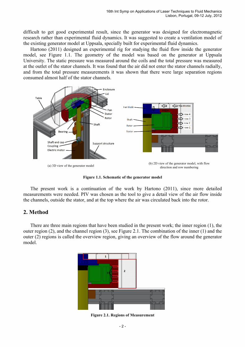
difficult to get good experimental result, since the generator was designed for electromagnetic research rather than experimental fluid dynamics. It was suggested to create a ventilation model of the existing generator model at Uppsala, specially built for experimental fluid dynamics. Hartono (2011) designed an experimental rig for studying the fluid flow inside the generator model, see Figure 1.1. The geometry of the model was based on the generator at Uppsala University. The static pressure was measured around the coils and the total pressure was measured at the outlet of the stator channels. It was found that the air did not enter the stator channels radially, and from the total pressure measurements it was shown that there were large separation regions consumed almost half of the stator channels.
Figure 1.1. Schematic of the generator model
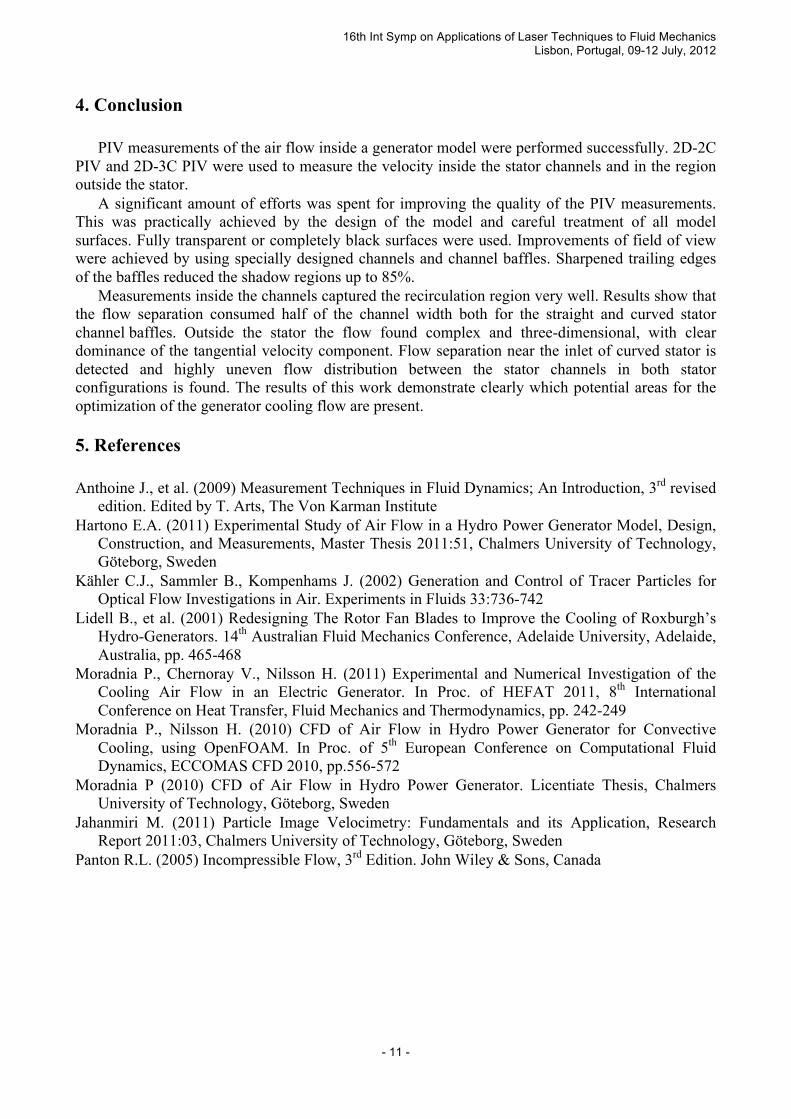
The present work is a continuation of the work by Hartono (2011), since more detailed measurements were needed. PIV was chosen as the tool to give a detail view of the air flow inside the channels, outside the stator, and at the top where the air was circulated back into the rotor. 2. Method There are three main regions that have been studied in the present work; the inner region (1), the outer region (2), and the channel region (3), see Figure 2.1. The combination of the inner (1) and the outer (2) regions is called the overview region, giving an overview of the flow around the generator model.
Figure 2.1. Regions of Measurement
(a) 3D view of the generator model (b) 2D view of the generator model, with flow
direction and row numbering

16th Int Symp on Applications of Laser Techniques to Fluid Mechanics Lisbon, Portugal, 09-12 July, 2012
- 3 -
Two-dimension two-component (2D-2C) PIV was used to measure the velocity field inside the stator channels (regions number 3 in Figure 2.1). The flow was measured at the channel symmetry plane. The flow outside the stator is highly three-dimensional, so in that region (see region number 1 and 2 in Figure 2.1) two-dimension three-component (2D-3C) PIV was used to measure the air velocity. Figure 2.2 shows an illustration of the PIV setup for this case.
Figure 2.2. PIV setup
The PIV system consisted of two Imager ProX4M cameras having 2048×2048 pix2 sensors, a double pulse Nd:YAG laser and synchronizing unit. The laser sheet optics and the cameras were fastened at a single frame to enable traversing the system in vertical direction. Measurements at the inner and outer regions were performed by consecutive vertical shifting of horizontal measurement plane inside the measurement region. Five measurement planes were used in the inner region and ten planes in the outer region to obtain data which then were interpolated to get entire picture of the flow inside the enclosure. Preliminary tests showed that laser light scattering on surfaces and edges of the rotor and stator in some areas was strong and exceeding intensity of light scattered by tracer particles. In order to improve the optical conditions and increase signal-to-noise ratio of PIV images modifications were made of the rotor, stator, and channel inserts. The rotor, stator and some elements of the channel inserts were black painted to reduce the reflection and scattering.
Figure 2.3. Channel Inserts; from left to right: straight channel, dummy channel, curved channel insert
A dummy channel insert was manufactured which has no coils and baffles inside. The purpose
(a) 2D-2C PIV Setup (b) 2D-3C PIV Setup

16th Int Symp on Applications of Laser Techniques to Fluid Mechanics Lisbon, Portugal, 09-12 July, 2012
- 4 -
of having this channel is to maximize the optical access during flow measurement in the middle rows of the stator (row 2 and 3), see Figure 1. The dummy channel was inserted in the outermost channel, giving the camera full view. Since the dummy channel has no coils and baffles, vertical plate inserts were placed at the channel inlet to provide the same blockage effect as if there was coils and baffles inside the channel. As seen in Figure 2.2, the laser was directed radially inwards through the channel. The stator baffles were obstructing the light and introducing shadows, especially for the curved stator configuration. To avoid the shadows in the curved stator configuration the baffles of the channel inserts were made transparent, and the trailing edge was sharpened to reduce the shadow from it. Figure 2.4 shows a comparison between the shadows from modified and unmodified baffles. As seen the width of the shadow is reduced up to 85% due to this modification. One can also observe significant reduction of reflections for the modified channel since all surfaces were carefully treated and painted.
Figure 2.4. Comparison of shadow region size
Different methods of flow seeding were tested and the best result was obtained with atomizer which was in-house built for this project. The construction of particle generator is based on the particle generator described in Kähler et al. (2002) see illustration in Figure 2.5. The mean size of generated droplets was approximately 1 µm when running continuously.
Figure 2.5. In-house particle generator
(a) Shadow region before the baffle tail was modified
(b) Shadow region after the baffle tail was modified

16th Int Symp on Applications of Laser Techniques to Fluid Mechanics Lisbon, Portugal, 09-12 July, 2012
- 5 -
3. Results and Discussion Two stator configurations were studied and compared. In both cases the rotor rotation speed was fixed to 2000 rpm. The results are presented in terms of radial, axial and tangential velocity components. Those have positive values radially outwards, vertically upwards, and anti-clockwise when looking from above, respectively, as shown in Figure 3.1.
Figure 3.1. Sign convention
Figure 3.2 shows that the flow in the inner region is dominated by the tangential component. The flow in this region is strongly affected by the shaft rotation which diffuses the angular momentum upstream into the entire generator enclosure.
Figure 3.2. Contour plots of velocity components in a radial-axial plane in the inner region, for the stators with
curved and straight baffles, respectively. The tangential velocity reduces as the radius increase and reaches zero at the enclosure wall. The tangential velocity for the curved stator has lower magnitude, compared to straight stator. This phenomenon is most probably due to the fact that in the curved stator the additional swirl outside the stator is created by the baffles directing the flow tangentially. This swirl is added to the mainstream. Another important result is found from considerations of Figures 3.2 (c) and (d). As one can expect the flow near the inlet should be directed into the inlet gap near the shaft, meaning a negative radial velocity component. This negative value is seen as expected in Figure 3.2 (d), for the straight stator. However, in the curved stator, the negative values were found only very close to the wall. Further away from the wall, there was a separation region with zero and some small positive radial velocity. The presence of the separation region is negatively affecting the flow losses. Figure 3.3 shows contour plots of the velocity distribution in the outer region. The outlets of the channels were located at heights 41, 72, 113, and 134 mm. The same conclusion as before can be drawn, that the flow inside the enclosure wall was dominated by the tangential component. Very complex structure of the flow in the outer region can be observed. For the straight stator configuration the radial and axial velocity components reveal larger magnitudes, which is positive
axial
radial
tangential

16th Int Symp on Applications of Laser Techniques to Fluid Mechanics Lisbon, Portugal, 09-12 July, 2012
- 6 -
in our case since one can expect better cooling performance with larger air massflow. Figure 3.4 shows the full picture of the flow pattern in the generator model. From this figures better understanding of the flow was achieved. The flow is ejected upward after exiting the channel outlet. One can clearly see that two bottom rows perform better than two rows above them. This is probably due to downward motion at the exit of upper channel rows, as seen in Figure 3.4 (e) and (f). A few recirculation regions can be observed between channel rows and larger recirculation region at the bottom corner near the enclosure wall. Figures 3.5 and 3.6 show the measurement results inside the curved and straight stator channels, respectively. ‘Inlet’ and ‘outlet’ line were chosen at the region where the data was good. These lines were created to study the inlet and outlet velocity distribution when entering and exiting the stator channel. The results show that the direction of the flow is mainly controlled by the stator baffles. The flow follows perfectly the baffles. Behind each coil there is a recirculation region that consumes almost half of the channel width. This phenomenon occurred in both the straight and curved channels. The channel inlet velocity, and thus the flow, was largest at row number 2.

16th Int Symp on Applications of Laser Techniques to Fluid Mechanics Lisbon, Portugal, 09-12 July, 2012
- 7 -
Figure 3.3. Contour plot of velocity components in a radial-axial plane in the outer region, for the stators with
curved and straight baffles, respectively
(a) Curved stator, tangential velocity component
(b) Straight stator, tangential velocity component
(c) Curved stator, radial velocity component
(d) Straight stator, radial velocity component
(e) Curved stator, axial velocity component
(f) Straight stator, axial velocity component

16th Int Symp on Applications of Laser Techniques to Fluid Mechanics Lisbon, Portugal, 09-12 July, 2012
- 8 -
Figure 3.4. Contour plot of velocity components in a radial-axial plane in the overview region, for the stators
with curved and straight baffles, respectively
(a) Curved stator, tangential velocity component (b) Straight stator, tangential velocity component
(c) Curved stator, radial velocity component (d) Straight stator, radial velocity component
(e) Curved stator, axial velocity component (f) Straight stator, axial velocity component

16th Int Symp on Applications of Laser Techniques to Fluid Mechanics Lisbon, Portugal, 09-12 July, 2012
- 9 -
Figure 3.5. Velocity distributions inside the curved channels
(a) Velocity profile at ’inlet’ and ’outlet’ at row 1 in curved channel (b) Velocity vector plot at row 1 in curved channel stator
(c) Velocity profile at ’inlet’ and ’outlet’ at row 2 in curved channel (d) Velocity vector plot at row 2 in curved channel
(e) Velocity profile at ’inlet’ and ’outlet’ at row 3 in curved channel (f) Velocity vector plot at row 3 in curved channel
(h) Velocity vector plot at row 4 in curved channel
’inlet’ line
’outlet’ line
’inlet’ line
’inlet’ line
’inlet’ line
’outlet’ line
’outlet’ line
’outlet’ line
(g) Velocity profile at ’inlet’ and ’outlet’ at row 4 in curved channel

16th Int Symp on Applications of Laser Techniques to Fluid Mechanics Lisbon, Portugal, 09-12 July, 2012
- 10 -
Figure 3.6. Velocity distribution inside the straight channels
(a) Velocity profile at ’inlet’ and ’outlet’ at row 1 in straight channel (b) Velocity vector plot at row 1 in straight channel
(c) Velocity profile at ’inlet’ and ’outlet’ at row 2 in straight channel (d) Velocity vector plot at row 2 in straight channel
(e) Velocity profile at ’inlet’ and ’outlet’ at row 3 in straight channel (f) Velocity vector plot at row 3 in straight channel
(g) Velocity profile at ’inlet’ and ’outlet’ at row 4 in straight channel (h) Velocity vector plot at row 4 in straight channel
’inlet’ line
’outlet’ line
’inlet’ line
’inlet’ line
’outlet’ line
’outlet’ line
’outlet’ line
’inlet’ line
16th Int Symp on Applications of Laser Techniques to Fluid Mechanics Lisbon, Portugal, 09-12 July, 2012
- 11 -
4. Conclusion PIV measurements of the air flow inside a generator model were performed successfully. 2D-2C PIV and 2D-3C PIV were used to measure the velocity inside the stator channels and in the region outside the stator. A significant amount of efforts was spent for improving the quality of the PIV measurements. This was practically achieved by the design of the model and careful treatment of all model surfaces. Fully transparent or completely black surfaces were used. Improvements of field of view were achieved by using specially designed channels and channel baffles. Sharpened trailing edges of the baffles reduced the shadow regions up to 85%. Measurements inside the channels captured the recirculation region very well. Results show that the flow separation consumed half of the channel width both for the straight and curved stator channel baffles. Outside the stator the flow found complex and three-dimensional, with clear dominance of the tangential velocity component. Flow separation near the inlet of curved stator is detected and highly uneven flow distribution between the stator channels in both stator configurations is found. The results of this work demonstrate clearly which potential areas for the optimization of the generator cooling flow are present. 5. References Anthoine J., et al. (2009) Measurement Techniques in Fluid Dynamics; An Introduction, 3rd revised
edition. Edited by T. Arts, The Von Karman Institute Hartono E.A. (2011) Experimental Study of Air Flow in a Hydro Power Generator Model, Design,
Construction, and Measurements, Master Thesis 2011:51, Chalmers University of Technology, Göteborg, Sweden
Kähler C.J., Sammler B., Kompenhams J. (2002) Generation and Control of Tracer Particles for Optical Flow Investigations in Air. Experiments in Fluids 33:736-742
Lidell B., et al. (2001) Redesigning The Rotor Fan Blades to Improve the Cooling of Roxburgh’s Hydro-Generators. 14th Australian Fluid Mechanics Conference, Adelaide University, Adelaide, Australia, pp. 465-468
Moradnia P., Chernoray V., Nilsson H. (2011) Experimental and Numerical Investigation of the Cooling Air Flow in an Electric Generator. In Proc. of HEFAT 2011, 8th International Conference on Heat Transfer, Fluid Mechanics and Thermodynamics, pp. 242-249
Moradnia P., Nilsson H. (2010) CFD of Air Flow in Hydro Power Generator for Convective Cooling, using OpenFOAM. In Proc. of 5th European Conference on Computational Fluid Dynamics, ECCOMAS CFD 2010, pp.556-572
Moradnia P (2010) CFD of Air Flow in Hydro Power Generator. Licentiate Thesis, Chalmers University of Technology, Göteborg, Sweden
Jahanmiri M. (2011) Particle Image Velocimetry: Fundamentals and its Application, Research Report 2011:03, Chalmers University of Technology, Göteborg, Sweden
Panton R.L. (2005) Incompressible Flow, 3rd Edition. John Wiley & Sons, Canada