Embed Size (px)
Citation preview

�������������Placer�County�LID Guidebook�March�2012��������������������������Chapter�4��LID�Site�Design�and�Runoff�Management��Measures�|�4Ͳ1�
Chapter 4
CHAPTER 4 LID SITE DESIGN AND RUNOFF MANAGEMENT MEASURES
This chapter provides information – including fact sheets – for twelve recommended Low Impact Development (LID) measures for use in the High Sierra areas of Placer County. Four of the measures (site design measures) relate to design and layout of the site and are mostly non-structural in nature, therefore tend to be the least expensive to implement. Projects utilizing as many site design measures as possible are more likely to require less of the runoff reduction measures. The remaining eight measures (runoff management measures) are more structural in nature and entail installation of physical components on the site.
Site design measures:
x SD-1 Protect Natural Conditions and Sensitive Areas
x SD-2 Optimize Site Layout
x SD-3 Control Pollutants at Source
x SD-4 Integrate Eco-Friendly Landscaping
Runoff management measures:
x RM-1 Stormwater Disconnection
x RM-2 Rainwater and Snowmelt Harvesting
x RM-3 Infiltration Trench/Dry Well
x RM-4 Bioretention
x RM-5 Vegetated Filter Strip
x RM-6 Vegetated Swale
x RM-7 Permeable Pavement
x RM-8 Green Roof
Fact sheets for each LID measures are included in this chapter and repeated in Appendix F for easy reference.
Projects utilizing as many site design measures as possible are more likely to require less physical controls to convey and manage site runoff and therefore may result in lower project costs. It is important to engage the entire design team (e.g., planner, engineers, architect, and landscape designer) early in the process to select the appropriate mix of LID measures to be integrated into the site design.
�

�������������Placer�County�LID Guidebook�March�2012��������������������������Chapter�4��LID�Site�Design�and�Runoff�Management��Measures�|�4Ͳ2�
The LID Selection Matrix (Figure 4-1) should be used in conjunction with the fact sheets presented later in this chapter and in Appendix F.
4.1 GUIDANCE FOR SELECTING APPROPRIATE LID MEASURES
It is important to understand the local landscape and regional context of the development site to get inspiration for designing stormwater management and LID systems that are functionally effective, efficient and complementary to the environment and the community of which they are a part. There are several basic strategies to address stormwater management objectives at the broad scale. For example, an area with predominantly well-drained soils signals the potential to develop a stormwater strategy based primarily on infiltration practices. In contrast, sites located in areas with more impervious clay-based soils will require the designer to explore strategies that employ a combination of storage, filtration, harvesting, evapotranspiration and infiltration practices to achieve stormwater management objectives.
The LID Selection Matrix (Figure 4-1) is an informative tool to assist with comparing and selecting the appropriate mix of LID measures for the development project, considering site conditions, performance of the measure, implementation concerns (e.g., costs and maintenance), and co-benefits (e.g., provides habitat, improves air quality). For each of the 12 recommended LID measures, basic site criteria are provided and relative ratings are given for performance, costs, and co-benefits.
Site Condition Factors
Design criteria are outlined in the matrix relative to the following site conditions (some of these factors were introduced in Chapter 3):
x Minimum Soil Infiltration Rate Requirement – There is a minimum vertical infiltration rate associated with the RM measure. Soil types A and B (sandy soils) will likely meet these requirements, but soil types C and D (clay) will not likely meet the infiltration rate required so that water infiltrates within 48 hours. Soils with less than 1 in/hr infiltration rates can be amended to increase infiltration, or an underdrain can be installed.
x Minimum Required Head Requirement (for LID measure under consideration) – A certain amount of fall or elevation difference (e.g. 3 ft) from the inlet to the outlet of the RM measure is required so that water flows through the measure.
x Setback Distance (from structures, foundations) – Certain infiltration measures need to be set back a sufficient distance (e.g., 20 feet) so that infiltrated water does not impact building foundations.
�������������Placer�County�LID Guidebook�March�2012��������������������������Chapter�4��LID�Site�Design�and�Runoff�Management��Measures�|�4Ͳ3�
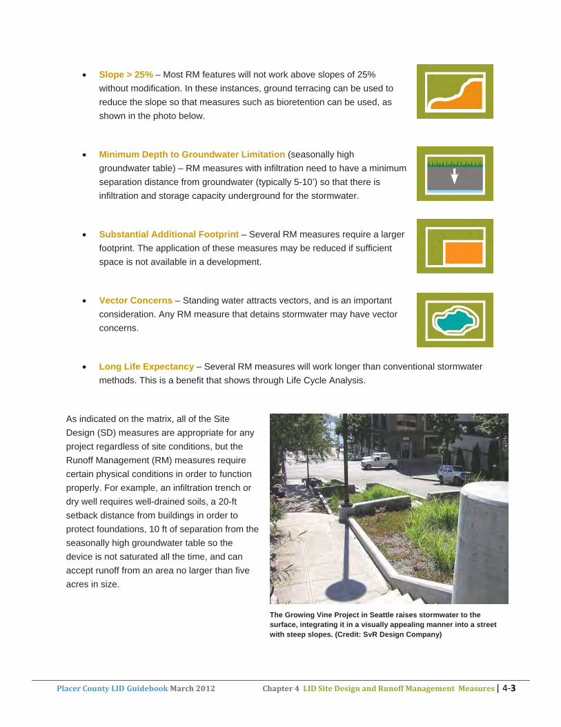
x Slope > 25% – Most RM features will not work above slopes of 25% without modification. In these instances, ground terracing can be used to reduce the slope so that measures such as bioretention can be used, as shown in the photo below.
x Minimum Depth to Groundwater Limitation (seasonally high groundwater table) – RM measures with infiltration need to have a minimum separation distance from groundwater (typically 5-10’) so that there is infiltration and storage capacity underground for the stormwater.
x Substantial Additional Footprint – Several RM measures require a larger footprint. The application of these measures may be reduced if sufficient space is not available in a development.
x Vector Concerns – Standing water attracts vectors, and is an important consideration. Any RM measure that detains stormwater may have vector concerns.
x Long Life Expectancy – Several RM measures will work longer than conventional stormwater methods. This is a benefit that shows through Life Cycle Analysis.
As indicated on the matrix, all of the Site Design (SD) measures are appropriate for any project regardless of site conditions, but the Runoff Management (RM) measures require certain physical conditions in order to function properly. For example, an infiltration trench or dry well requires well-drained soils, a 20-ft setback distance from buildings in order to protect foundations, 10 ft of separation from the seasonally high groundwater table so the device is not saturated all the time, and can accept runoff from an area no larger than five acres in size.
The Growing Vine Project in Seattle raises stormwater to the surface, integrating it in a visually appealing manner into a street with steep slopes. (Credit: SvR Design Company)�

Low�Impact�Development�(LID)�Measure Minim
um�In
filtration
�Rate�Re
quirem
ent
Minim
um�Head�Re
quirem
ent
Setback�Distance�Re
quirem
ent
Slop
e�>�25%
Minim
um�Dep
th�to�Groun
dwater�Lim
itation
Substantial�A
dditiona
l�Foo
tprint
Vector�Co
ncerns
Long
�Life�Expe
ctan
cy,�>=�20
�years
Provides�Deten
tion
�/�Im
poun
dmen
t�Storage
Increases�SW
�Run
off�T
ravel�Tim
e
Redu
ces�Volum
e�of�Overall�SW
�Run
off
Metals�Re
duction
Nutrien
t�Red
uction
Oil�an
d�Grease/�Hydrocarbon
�Red
uction
Sedimen
t�Re
duction
Tempe
rature�Red
uction
Construction
�Co st�($�/�cf)�(b
)
Construction
�Cost�($�/�fe
ature)�(c
)
Ann
ual�O
&M�Cost�($)�(
d)
Redu
ces�Pu
blic�Agency�Mainten
ance�Costs
High�Elevation�Winter�C
ondition
s�(e)
Provides�Evapo
tran
spiration�(ET)
Provides�Hab
itat
Prom
otes�GW�Recha
rge
Provides�Sha
de�(R
educes�Heat�Islan
d�Effect)
Redu
ces�Green
house�Gases
Redu
ces�En
ergy�Use
Aesthetically�Pleasing
Redu
ces�Dow
nstream�Erosion
�and
�Flood
ing
Enha
nces�Prope
rty�Value
ID LID�Site�Design�(SD)�Measures
SDͲ1Protect�Natural�Conditions�and�Sensitive�Areas Ⴜ Ⴜ Ⴠ Ⴜ Ⴠ Ⴜ Ⴠ Ⴜ $ $ $ Ⴜ Ⴠ Ⴠ Ⴠ Ⴠ Ⴠ Ⴜ Ⴜ Ⴠ Ⴡ Ⴠ
SDͲ2 Optimize�Site�Layout Ⴡ Ⴡ Ⴠ Ⴡ Ⴡ Ⴡ Ⴠ Ⴡ $ $ $ Ⴡ Ⴠ Ⴠ Ⴡ Ⴡ Ⴡ Ⴜ Ⴜ Ⴠ Ⴡ ჀSDͲ3 Control�Pollutants�at�Source Ⴠ Ⴜ Ⴠ Ⴠ $ $ $$ Ⴡ Ⴜ Ⴡ ჁSDͲ4 Integrate EcoͲFriendly Landscaping Ⴜ Ⴜ Ⴠ Ⴜ Ⴠ Ⴜ Ⴠ Ⴜ $ $ $ Ⴜ Ⴡ Ⴠ Ⴡ Ⴡ Ⴠ Ⴜ Ⴜ Ⴠ Ⴡ Ⴡ
Site�Condition�Factors�do�not�limit�the�application�of�Site�Design�Measures
Low�Impact�Development�Selection�Matrix�for�Placer�County�GuidebookSite�Condition�Factors�(a) Runoff�Control Pollutant�Control Implementation Ancillary�Benefits
Legend:
Ɣ Very�Effective
٩ Moderately�Effective
ż Mildly�EffectiveX����Applicable
Not�Applicable
SDͲ4 Integrate�EcoͲFriendly�Landscaping Ⴜ Ⴜ Ⴠ Ⴜ Ⴠ Ⴜ Ⴠ Ⴜ $ $ $ Ⴜ Ⴡ Ⴠ Ⴡ Ⴡ Ⴠ Ⴜ Ⴜ Ⴠ Ⴡ ჁLID�Runoff�Management�(RM)�Measures
RMͲ1 Stormwater�Disconnection X X X X Ⴡ Ⴠ Ⴠ Ⴠ Ⴠ Ⴠ Ⴠ Ⴠ $ $ $ Ⴜ Ⴡ Ⴡ Ⴜ Ⴡ Ⴜ Ⴡ Ⴡ Ⴠ ჁRMͲ2 Rainwater�and�Snowmelt�Harvesting X X X Ⴠ Ⴠ $$$ $$ $$ Ⴡ Ⴠ Ⴜ Ⴡ Ⴡ ჀRMͲ3 Infiltration�Trench�/�Dry�Well X X X X X X Ⴡ Ⴜ Ⴠ Ⴜ Ⴠ $$$ $$ $$$ Ⴡ Ⴡ Ⴠ Ⴡ ႼRMͲ4 Bioretention X X X Ⴠ Ⴠ Ⴠ Ⴠ Ⴠ Ⴠ Ⴠ Ⴠ $$ $$$ $$ Ⴜ Ⴜ Ⴠ Ⴡ Ⴠ Ⴜ Ⴠ Ⴡ Ⴠ Ⴠ ჀRMͲ5 Vegetated�Filter�Strip X X X X X Ⴜ Ⴡ Ⴠ Ⴜ Ⴜ Ⴜ Ⴡ Ⴜ $ $ $ Ⴡ Ⴠ Ⴡ Ⴜ Ⴜ Ⴜ Ⴡ Ⴡ Ⴠ ႼRMͲ6 Vegetated�Swale X X X X X X X Ⴠ Ⴠ Ⴠ Ⴡ Ⴠ Ⴠ Ⴠ Ⴠ $ $ $$ Ⴡ Ⴡ Ⴠ Ⴠ Ⴠ Ⴜ Ⴠ Ⴜ Ⴠ Ⴠ ჁRMͲ7 Permeable�Pavement X X X X X Ⴠ Ⴠ Ⴠ Ⴠ Ⴠ Ⴠ Ⴠ $$ $$$ $$$ Ⴜ Ⴡ Ⴠ Ⴠ ჀRMͲ8 Green�Roof X X Ⴜ Ⴠ Ⴠ $$$ $$$ $$$ Ⴡ Ⴠ Ⴡ Ⴜ Ⴠ Ⴠ Ⴠ Ⴠ Ⴡ Ⴠ
Notes:�Information�presented�in�this�matrix�is�based�on�published,�national�literature�and�is�intended�for�planning�purposes�only.�Check�References�section�of�the�LID�Guidebook�for�sources�of�data.
Other�Best�Management�Practices�(BMPs)�such�as�detention�basins�and�constructed�wetlands�are�not�considered�“small�scale�controls”�and�therefore�are�not�included�in�this�Guidebook.��During�large�storm�events�(when�groundwater�and�soil�is�saturated),�these�measures�will�provide�little,�if�any,�hydraulic�management.
(a) Specific�rates�and�distances�for�each�site�condition�factor�are�provided�in�SD�and�RM�fact�sheets.�
(b) Construction�Cost�($�/�cf)�(2006�dollars) $�=�<�$3��� $$�=�$3�Ͳ�$15 $$$�=�>�$15
(c) Construction�Cost�($�/�feature)�(2006�dollars) $�=�$0�Ͳ�$10,000��� $$�=�$10,000�Ͳ�$50,000 $$$�=�>�$50,000
(d) Annual�O&M�Cost�($�/�feature)�(2006�dollars) $�=�<�$1,000 $$�=�$1,000�Ͳ�$5,000 $$$�=�>$�5,000(e) Relative�effectiveness�ratings�are�based�on�comparison�of�the�various�practices�to�each�other�for�use�in�High�Sierra,�rather�than�comparing�the�practices�used�in�High�Sierra�to�those�on�the�valley�floor.
Revised March 2012

�������������Placer�County�LID Guidebook�March�2012��������������������������Chapter�4��LID�Site�Design�and�Runoff�Management��Measures�|�4Ͳ5�
The design of some measures can be modified to function in less than ideal site conditions. For example, in poorly draining clay soils, bioretention stormwater planters can be fitted with under drains and/or overflow weirs to carry excess water to the street gutter and/or local storm drain system. In cases where there is a large contributing drainage area, designers can break up the site into several drainage sheds, each handled by a different LID measure, or use several of the measures in parallel or series to accommodate the expected site runoff (stormwater and irrigation) flows. Information is provided in this chapter for alternative design modifications/configurations as applicable.
Runoff Control Factors
Three Runoff Control factors are included in the selection matrix:
x Provides Detention/Retention Storage
x Increases Stormwater Runoff Travel Time
x Reduces Volume of Overall Stormwater Runoff
Several of the RM measures provide detention, and all of the site design and runoff management measures reduce the volume of overall stormwater runoff, with the exception of SD-3 Control Pollutants at Source.
Pollutant Control Factors
The following Pollutant Control factors are included in the selection matrix:
x Metals Reduction
x Nutrient Reduction
x Oil and Grease/ Hydrocarbon Reduction
x Sediment Reduction
x Temperature Reduction
Some of the RM measures provide treatment for some of these constituents, whereas three measures (stormwater flowpath disconnection, bioretention, and vegetated swale) provide treatment for all of these constituents. Additional information on stormwater quality is provided as follows.
The water quality concerns associated with stormwater and resulting regulatory requirements for protection of receiving water quality are of paramount importance in LID design. Table 4-1 shows pollutants commonly found in urban runoff. A particular constituent of concern for Placer County is sediment. Table 4-2 outlines typical pollutant source areas and runoff characteristics on a development site, along with potential opportunities for stormwater treatment and LID.
Typically the primary goal with LID design is runoff reduction. It may or may not satisfy all of the permitting agency’s stormwater quality requirements. However, using infiltration-based LID features can reduce the volume of runoff to be managed and treated, therefore reducing the amount of storm drain piping and the size of stormwater treatment facilities, which saves buildable land and costs.

�������������Placer�County�LID Guidebook�March�2012��������������������������Chapter�4��LID�Site�Design�and�Runoff�Management��Measures�|�4Ͳ6�
Table 4-1. Pollutants Commonly Found in Urban Runoff
Pollutant Major Sources Potential Effects
Nutrients
x Nitrogen x Phosphorus
x Fertilizers x Animal waste x Detergents x Atmospheric deposition x Leaking sanitary sewer pipes
x Lowers oxygen levels x Destroys habitat x Promotes algal blooms x Limits recreation x Interferes with navigation
Pathogens
x Bacteria x Viruses
x Animal waste x Illicit connections between
sewage lines and storm drains
x Leaking sanitary sewer pipes
x Poses human health risks x Closes beaches x Closes shellfish harvesting areas
Hydrocarbons
x Oil x Grease x Petroleum products x Polycyclic aromatic
hydrocarbons (PAHs)
x Roads x Parking lots x Automobile emissions x Improper disposal of used
motor oil x Illicit connections
x Lowers dissolved oxygen levels x Causes toxic impacts x Damages habitat
Toxic Organics
x Pesticides x Polychlorinated
biphenyls (PCBs)
x Lawn and garden care x Agricultural lands x Industrial uses x Illicit connections
x Toxic impacts x Leads to human and animal
reproductive abnormalities x Increases animal mortality rates
Sediment x Construction sites x Agricultural lands x Logged forest lands x Eroded streambanks
x Increases turbidity (cloudiness) x Alters water flows x Destroys benthic habitat x Blocks sunlight x Attracts particulate forms of
metals and nutrients Source: City of Reno, 2007.
�

�������������Placer�County�LID Guidebook�March�2012��������������������������Chapter�4��LID�Site�Design�and�Runoff�Management��Measures�|�4Ͳ7�
Table 4-2. Types of stormwater source areas, typical runoff characteristics and opportunities for stormwater management (adapted from TRCA, 2010)
SW Source Area Runoff Characteristics Opportunities Principles Foundation drains, slab under drains, road or parking lot under drains
Relatively clean, cool water.
Suitable for infiltration or direct discharge to receiving watercourses.
Should not be directed to stormwater management facility that receives road or parking lot runoff.
Roof drains, roof terrace area drains, overflow from green roofs
Moderately clean water, contaminants may include asphalt granules, low levels of hydrocarbons and metals from decomposition of roofing materials, animal droppings, natural organic matter and fallout from airborne pollutants, potentially warm water.
- Infiltration; - Filtration; - Harvesting with rain barrels or cisterns and use for non-potable purposes (e.g., irrigation, toilet flushing) after pretreatment;
- Attenuation and treatment in wet pond or wetland detention facility.
Runoff should be treated with a sedimentation and/or filtration practice prior to infiltration. Where possible, runoff should not be directed to end-of-pipe facilities to capitalize on potential for infiltration or harvesting. Flow moderation (quantity control) prior to discharge to receiving watercourse is required.
Low and medium traffic roads and parking lots, driveways, pedestrian plazas, walkways
Moderately clean water, contaminants may include low levels of sediment, de-icing salt constituents, hydrocarbons, metals and natural organic matter. Typically warm water.
- Infiltration after pretreatment; - Filtration after pre-treatment; - Harvesting with cisterns or permeable pavement reservoirs and use for outdoor non-potable purposes (e.g., vehicle washing, irrigation) after pretreatment;
- Attenuation and treatment in wet pond or wetland detention facility.
Runoff should be treated with a sedimentation and/or filtration practice prior to infiltration. Flow moderation (quantity control) prior to discharge to receiving watercourse is required. Water quality should be tested prior to use for non-potable purposes.
High traffic roads and parking lots
Potential for high levels of contamination with sediment, de-icing salt constituents hydrocarbons and metals. Typically warm water.
- Filtration after sedimentation pre-treatment; - Attenuation and treatment in wet pond or wetland detention facility; - Infiltration after pretreatment only where groundwater uses are limited.
Runoff should be treated with a sedimentation and/or filtration pretreatment practice prior to infiltration.
Pollution hot spots* such as vehicle fueling, servicing or demolition areas, outdoor storage and handling areas for hazardous materials, some heavy industry sites
Potential for high levels of contamination with sediment, de-icing salt constituents, hydrocarbons, metals, and other toxicants.
- Attenuation and treatment in wet pond, wetland or hybrid detention facility; - Potential requirement for sedimentation pretreatment; - Infiltration and harvesting practices not recommended.
Runoff from these sources should not be infiltrated or used for irrigation. Spill containment or mitigation devices recommended contingent on size of storage facilities.
* Pollution hot spots are areas where certain land uses or activities have the potential to generate highly contaminated runoff (e.g., vehicle fuelling, service or demolition areas, outdoor storage and handling areas for hazardous materials and some heavy industry sites).

�������������Placer�County�LID Guidebook�March�2012��������������������������Chapter�4��LID�Site�Design�and�Runoff�Management��Measures�|�4Ͳ8�
The following implementation factors are noted on the matrix:
x Construction Cost (per cubic foot and per feature)
x Annual Operations and Maintenance Cost
x Reduces Public Agency Maintenance Costs
x High Elevation Winter Conditions
The Site Design (SD) measures typically have low or moderate construction costs as compared to implementing the Runoff Management (RM) measures at high elevations. Moreover, the SD measures would have significantly less cost than conventional stormwater management systems, but would not provide adequate stormwater management without being combined with RM measures. Any physical site features conserved or put in place as result of using any of the measures (e.g., protected natural areas, covers on trash enclosures to control pollutant sources, or new eco-friendly landscaping) are fairly easy to maintain, and therefore have a lower annual Operations and Maintenance (O&M) cost than RM features.
Construction costs and annual O&M costs vary greatly in the eight recommended LID RM Measures. Construction costs and annual O&M costs for stormwater flowpath disconnection (RM-1), vegetated filter strips (RM-5), and vegetated swales (RM-6) are typically lower than the other RM measures when installed at high elevations. It should be noted, however, that there is a wide range in construction costs based on how simple or complex the RM design is; therefore, a simple bioretention system (rain garden) could actually cost less to construct than a complex tiered vegetated swale with inlet/outlet control. Typically, LID RM features will cost less than conventional stormwater methods, but again, the construction cost will typically follow how complex the design is and what construction materials are necessary for the measures. Permeable pavement (RM-7) and green roofs (RM-8) are likely to cost more to construct than other RM measures and conventional systems due to materials required and additional maintenance over their lifetimes. However, these types of systems provide many other benefits that can reduce life-cycle costs as compared to conventional techniques, as described below. Specific cost data for SD and RM measures are provided in the LID Selection Matrix.
The matrix also rates the recommended LID measures with respect to their performance in high elevation winter conditions, such as those experienced in the High Sierra areas of Placer County. The basis for the ratings comes from nationally published literature (see References section of this Guidebook for source of data for each LID measure).
Additional information in these areas is described as follows.

�������������Placer�County�LID Guidebook�March�2012��������������������������Chapter�4��LID�Site�Design�and�Runoff�Management��Measures�|�4Ͳ9�
Construction and Life Cycle Costs
As discussed in Chapter 2, in addition to initial construction costs, operation and maintenance (O&M) cost evaluations should be evaluated when estimating the costs of LID and comparing to conventional stormwater management approaches. The fact sheets in Chapter 4 present the cost ranges for construction and O&M costs, based on published national literature (this information has also been translated to the LID Selection Matrix [Figure 4-1] as relative “low, medium, high” rankings.)
The value of using LID techniques becomes evident over time for several reasons. The initial capital costs for LID may appear higher because such features may cost more to design (e.g., the integrated design team approach discussed previously) or may result in a loss of buildable space, as compared to the traditional pipe, curb and gutter and pond systems. However, literature comparisons of LID versus conventional approaches (see Chapter 2) show that there can be construction cost savings due to the reduced amount of construction materials required for the LID approach. The LID approach uses de-centralized, somewhat modular techniques, located as close to the source of the runoff as possible and integrated into the site’s landscaping whenever possible, whereas the conventional approach requires piping, concrete curb and gutter, and ponds or below-ground structures for stormwater detention and treatment. Also, long-term maintenance costs for LID can be lower than conventional approaches. As residential density increases over time, conventional stormwater conveyance facilities may need to be enlarged to handle augmented flows from additional development, and aging infrastructure will need to be continuously maintained and eventually replaced. Since most LID features are installed above ground and use vegetation for the passive treatment component, long-term maintenance is projected to cost less.
When possible, a life-cycle analysis should be done to monetize the value of all benefits (e.g., energy and water savings, higher property values due to aesthetic and recreational amenities, multi-purpose benefits, and replacement costs) over the projected life of the LID techniques. When evaluating the entire life-cycle of the project, the LID approach will most likely compare more favorably to the conventional approach.
Maintenance Needs to Facilitate Continued Performance
Ongoing maintenance is critical for LID techniques to ensure long-term optimum performance. Aesthetic appearance can also be improved by maintenance (especially in the case of vegetative features), but is typically not required for enhanced treatment performance. The following provides a standard set of maintenance goals for LID features (Maintenance of Low Impact Development Facilities, 2007):

�������������Placer�County�LID Guidebook�March�2012��������������������������Chapter�4��LID�Site�Design�and�Runoff�Management��Measures�|�4Ͳ10�
Ensure the sufficient carrying capacity for emergency Flow Control and Drainage:
x Maintain pre-development infiltration capacity (reduce total volume of surface flows) and flow attenuation of facility.
x Maintain pre-development detention capability to reduce peak flows.
x Safely convey design storm flows.
Water Quality Treatment:
x Maintain pre-development infiltration and detention capability.
x Preserve soil and plant health and contact of storm flows with those plant soil systems.
Safety and Emergency Vehicle Access:
x Maintain adequate sight distances.
x Create signage for emergency vehicle access and facilitiesvehicles of any permeable load-bearing surfaces.
Cost Effectiveness:
x Maintain facilities for long-term, high quality performance at a cost that is equal to, or less than, conventional systems.
x Prevent expensive repair of large scale or catastrophic problems through continued routine procedures.
Aesthetics:
x Develop LID facilities as a landscape amenity as well as a stormwater management system.
Public Health:
x Minimize potential for disease transmission and mosquito breeding by maintaining designed infiltration capacity, storm flow conveyance, ponding depths, and dewatering rates.
Community Participation:
x Provide educational materials to homeowners and commercial property owners explaining the benefits, function, and importance of community participation for the long-term performance of LID facilities.

�������������Placer�County�LID Guidebook�March�2012��������������������������Chapter�4��LID�Site�Design�and�Runoff�Management��Measures�|�4Ͳ11�
Addressing Concerns About Potential Permeable Pavement Clogging at a Retail Project in New Hampshire
To address concerns about potential clogging of porous asphalt at the new Greenland Meadows retail shopping center in Greenland, New Hampshire, the design team equipped the porous pavement systems with relief valve designs. “This was a conservative ‘belt and suspenders’ approach to the porous asphalt design,” according to one of the project designers. “Although the porous pavement system is not anticipated to fail, this design and strategy provided the developers with a safety factor and insurance in the event of limited surface infiltration”.
To further alleviate the project owner’s concerns about potential clogging, a combination paving approach was used. Porous asphalt was limited to passenger vehicle areas and installed at the far end of the front main parking area as well as in the side parking area, while standard pavement was put in near the front and more visible sections of the retail center as well as the loop roads and delivery areas that were expected to receive truck traffic. “This way, in case there was clogging or a failure, it would be away from the front entrances and would not impair access or traffic into the stores,” according to one of the project’s designers.
Gunderson et al, 2011
High Elevation Winter Conditions - Performance in Placer County High Sierra Areas
The focus of this Guidebook is on the High Sierra areas of Placer County above 5,000 feet, which experience significant snowfall and snow retention from late fall to early spring. The high elevation climate poses concerns for performance of LID measures such as:
x Effect of freeze/thaw conditions on performance
x Concern with roadway sands clogging permeable pavements
x Inadequate growing season for green roofs and other vegetative features
x The negative impact of salt and deicers on vegetation and concrete
x Damage and debris loading from snow storage
x Rain on snow events
x Damage from snow removal equipment and operations
x Slope instability
x Hydrophobic soil
x Access issues due to snow storage
x Effect of consecutive winter seasons on long-term performance
Many of these concerns can be overcome through design modifications such as those summarized in Table 4-3 and described in the fact sheets for recommended LID measures.

�������������Placer�County�LID Guidebook�March�2012��������������������������Chapter�4��LID�Site�Design�and�Runoff�Management��Measures�|�4Ͳ12�
Table 4-3. High Elevation Winter Conditions Performance Concerns and Associated Design Modification Solutions
Potential Problem LID Measure Recommended Design Modification/Possible Solutions
Performance may decrease over time due to freeze/thaw cycling, which can negatively impact vegetation
RM-3 Infiltration RM-4 Bioretention RM-5 Filter Strip RM-6 Swale RM-8 Green Roof
• Cover the ground around plants and trees with a layer of mulch in the fall to prevent damage from repeated freeze/thaw cycling (mulch acts as insulation to keep the soil frozen and helps to prevent the cycling).
Road sands may clog the LID measures
RM-1 Flowpath Disconnection RM-5 Filter Strip RM-6 Swale RM-7 Permeable pavement
• Increase frequency of routine sediment removal, and check for clogging during late winter/ spring.
• Vacuum permeable pavements in the spring.
• Do not use permeable pavements in
areas where sand is used (e.g., highways and major roads).
• Restrict/eliminate sand usage in
areas with permeable pavement.
Relatively short growing season for vegetation
RM-4 BioretentionRM-5 Filter Strip RM-6 Swale RM-8 Green Roof
• Choose appropriate plant species for adequate growth in high elevations and cold climates (see Appendix A).
• Install erosion control measures such as mats or blankets while the vegetative cover becomes established. �
Use of salt or other deicing compounds may damage vegetation and concrete
RM-5 Filter Strip RM-6 Swale RM-7 Permeable Pavement
• Avoid using salt or other deicing compounds that react with concrete.
• Choose salt-tolerant plant species. Grasses are more tolerant than trees and woody plants.
• Incorporate mulch into the soil.

�������������Placer�County�LID Guidebook�March�2012��������������������������Chapter�4��LID�Site�Design�and�Runoff�Management��Measures�|�4Ͳ13�
Potential Problem LID Measure Recommended Design Modification/Possible Solutions
Snow storage impacts
RM-3 InfiltrationRM-4 Bioretention RM-5 Filter Strip RM-6 Swale RM-8 Green Roof
• Provide adequate snow storage areas, properly designed, and possibly with their own infiltration systems.
• Provide signage prohibiting stockpiling of snow on top of sensitive LID features, unless specifically intended as a snow melt system (note: this solution may be hard to enforce or impractical during extreme snow events)
• Schedule snow removal to limit period of time snow remains on top of LID features (care should be taken when removing snow so as not to displace vegetation; also, consider snowmelt harvesting benefits as melting snow infiltrates.
• Periodically amend soils (if possible,
remove and set aside top vegetation and replace after soil amendments are made).
• Install a hydronic or electric
snowmelt system.
Stored snow and rain on snow events will produce higher runoff than normal
RM-3 Infiltration RM-4 Bioretention RM-6 Swale RM-7 Permeable pavement
• Additional volume required for snow storage and increased runoff volume from rain on snow events should be taken into account when sizing storage volumes
Damage from snow removal equipment
RM-5 Filter Strip RM-6 Swale RM-7 Permeable pavement
• Raise blade level of snow removal equipment high enough to avoid damage to permeable pavement material or vegetation

�������������Placer�County�LID Guidebook�March�2012��������������������������Chapter�4��LID�Site�Design�and�Runoff�Management��Measures�|�4Ͳ14�
Potential Problem LID Measure Recommended Design Modification/Possible Solutions
Pipe Freezing, Frost Heave
RM-1 Flowpath DisconnectionRM-2 Rainwater Harvesting RM-3 Infiltration RM-4 Bioretention RM-5 Filter Strip RM-6 Swale RM-7 Permeable pavement
• Insert underground components below the frost line to prevent frost heave and to prevent water from freezing in pipes.
• For pipes that cannot be installed below the frost line, such as conveyance pipes used with cisterns, insulate or equip with heat tracing (electrical heating element run in physical contact along the length of a pipe, which is then covered with insulation)
Permanent pool ice covering may form on areas of stormwater detention impeding the function of the LID measure
RM-1 Flowpath DisconnectionRM-2 Rainwater Harvesting RM-3 Infiltration RM-4 Bioretention RM-6 Swale RM-7 Permeable pavement
• Provide a deeper sub base rock layer below permeable pavement to ensure good drainage of the runoff and emptying of the void spaces in the pavement before there is time for the water to freeze.
• Rainwater harvesting tank placement is recommended on the south side of the structure when possible to discourage ice build-up
Extreme or sustained cold temperatures can lead to reduced soil infiltration rates
RM-1 Flowpath DisconnectionRM-3 Infiltration RM-4 Bioretention RM-6 Swale RM-7 Permeable pavement
• Make allowance in site stormwater design for the fact that these LID measures will infiltrate site runoff effectively during part of the winter only (on days with above-freezing temperatures)
• Install an underdrain system to drain the ground beneath an infiltration system. The underdrain is used to drain the soils before the winter season begins, and then is closed throughout the winter.
• The bottoms of basins or trenches can be lined with one foot of gravel or sand to encourage infiltration.
Extreme or sustained cold temperatures may lead to reduced biological activity and settling velocities
RM-4 BioretentionRM-5 Filter Strip RM-6 Swale
• Size facilities for coldest temperature removal rates (assume decreased biological activity and settling during sustained cold temperatures)

�������������Placer�County�LID Guidebook�March�2012��������������������������Chapter�4��LID�Site�Design�and�Runoff�Management��Measures�|�4Ͳ15�
�
Ancillary Benefit Factors
Most of the recommended measures potentially provide ancillary benefits in addition to stormwater management, such as:
x Increased evapotranspiration x Provides habitat x Promotes groundwater recharge x Provides shade (reduces heat island effect) x Reduced greenhouse gases x Reduced energy use x Aesthetically pleasing x Reduced downstream erosion and flooding x Enhanced property value
Most of the recommended LID measures provide some level of effectiveness relative to the ancillary benefits listed above. Note that where vegetation is used (e.g., vegetated swale, green roof), ancillary benefits are provided almost across the board, demonstrating the advantage of using vegetative systems as much as practicable in LID design.

�������������Placer�County�LID Guidebook�March�2012��������������������������Chapter�4��LID�Site�Design�and�Runoff�Management��Measures�|�4Ͳ16�
4.2 LID MEASURE FACT SHEETS: OVERVIEW
This section of Chapter 4 contains fact sheets for the 12 recommended LID measures, which include site design and runoff management measures.
The following type of information is presented on a single double-sided fact sheet for each of the four Site Design (SD) measures:
x Brief Introduction
x Planning and Design Strategies
x Design Elements
x Opportunities and Benefits
x Limitations
x Construction, Installation and Maintenance Considerations (where applicable)
x Photos and Schematics (local conditions are shown whenever possible)
x References
Each of the eight Runoff Management (RM) fact sheets are presented as a single 11x17 page for easy at-a-glance reference in the office or in the field. These sheets contain the following type of information:
x General Description
o Planning and Design Strategies
o General Guidelines
o Design Strategies
o Benefits
o Limitations
x Cold Climate Considerations
x Construction Considerations
x Operations and Maintenance Considerations
x Water Quality Pollutant Percent Removals (where applicable)
x Photos and schematics (local conditions are shown whenever possible)
x References

�������������Placer�County�LID Guidebook�March�2012��������������������������Chapter�4��LID�Site�Design�and�Runoff�Management��Measures�|�4Ͳ17�
4.3 LID MEASURE FACT SHEETS: SITE DESIGN MEASURES
LID Site Design (SD) fact sheets are presented on a single double-sided fact sheet for each of the four measures, which include the following that are briefly introduced below:
x SD-1 Protect Natural Conditions and Sensitive Areas
x SD-2 Optimize Site Layout
x SD-3 Control Pollutants at Source
x SD-4 Integrate Eco-Friendly Landscaping
SD-1 Protect Natural Conditions and Sensitive Areas
Site design to preserve natural conditions is guided by the strategy to protect as much of the existing natural/vegetated areas and drainage features of the site as possible (including environmentally sensitive areas) and to minimize soil compaction in these areas during construction. Protecting natural areas and riparian buffers (if present) will improve water quality and reduce runoff velocities and flows through filtration and infiltration, enhance site aesthetics, and provide habitat. Additional benefits include cleaner air and carbon sequestration by trees and lower construction costs due to the reduced need for clearing, excavation and disposal, and structural stormwater conveyance facilities. See the SD-1 fact sheet for detailed information about this measure.
SD-2 Optimize Site Layout
Optimize Site Layout is a site design measure for minimizing the site footprint that can be applied to all projects. It is accomplished using strategies such as minimizing total disturbed area, reducing the amount of impervious surfaces, and integrating stormwater management features with buildings and vegetation. Key considerations include taking advantage of pre-project natural site conditions and looking for opportunities to install features that can serve multiple purposes. See the SD-2 fact sheet for detailed information about this measure.
Wide buffers around environmentally sensitive areas such as creeks will filter out pollutants and reduce runoff
Residential�LID�Site�Layout�(Source:�Puget�Sound�LID�Manual,�2005)

�������������Placer�County�LID Guidebook�March�2012��������������������������Chapter�4��LID�Site�Design�and�Runoff�Management��Measures�|�4Ͳ18�
SD-3 Control Pollutants at the Source
Control Pollutants at the Source is a site design measure for containing pollutants before they come into contact with water. Managing pollutants as close to the source as possible can minimize the cost of treatment and conveyance. Options include covering and containing storage areas (e.g., install roofs over trash enclosures), designing site features to keep pollutants out of storm drains (e.g., placing “no dumping” signs) and strategically locating areas with a likelihood of generating pollutants away from storm drains and water bodies. See the SD-3 fact sheet for detailed information about this measure.
”Start at the Source” (BAASMA, 1999) is an excellent reference for site design to minimize pollution and the cost of stormwater quality treatment.
SD-4 Integrate Eco-Friendly Landscaping
Integrate Eco-Friendly Landscaping is a site design measure that can be applied to most projects, including small urban infill projects and sites with steep slopes or clay soils. It entails specifying locations on the site plan where native and climate appropriate vegetation should be installed. Such landscaping will require less maintenance, water, fertilizers and pesticides. The design specifications should call for soil amendments as needed and water efficient irrigation for landscaped areas. Overall using eco-friendly landscaping can reduce water and energy use, provide habitat, and increase soil infiltration capacity. See the SD-4 fact sheet for detailed information about this measure.
Slope revegetation in Placer County (Photo: BobCosta, Placer County)
�

P L A C E R C O U N T Y L O W I M P A C T D E V E L O P M E N T G U I D E B O O K
Protect Natural Conditions
Fact Sheet SD-1
Protect Natural Conditions is a site design measure that can be applied to most projects, and includes preserving natural areas such as riparian buffers and tree clusters; protecting environmentally sensitive areas and designated open space; protecting natural drainage features; and minimizing soil compaction during site clearing and grading.
Planning and Design StrategiesSite design to preserve natural conditions is guided by these general strategies:• Protect as much of the existing natural/vegetated areas of the site as possible• Protect environmentally sensitive areas and designated open space• Preserve and use existing natural drainage features and flow paths whenever possible. If not
possible, restore these features to pre-project conditions• Minimize soil compaction during and after construction
Protect Natural Conditions Riparian Buffer: Riparian buffer areas are important elements of local communities’ green infrastructure and/or LID tool box. These areas are critical to the biological, chemical, and physical integrity of our waterways. Riparian buffer areas protect water quality by cooling water, stabilizing banks, mitigating flow rates, and providing for pollution and sediment removal by filtering overland sheet runoff before it enters the water. The Environmental Protection Agency defines buffer areas as, “areas of planted or preserved vegetation between developed land and surface water, [which] are effective at reducing sediment and nutrient loads.”
Trees and Tree Clusters: Tree conservation at development sites will help to maintain a natural hydrologic regime. If tree conservation is not an option, plant new trees in pervious areas of development sites. Tree clusters planted in turf grass or barren ground can reduce stormwater runoff volume and peak flow, improve water quality, generate organic soils, absorb greenhouse gases, create wildlife habitat, and provide shading to mitigate temperature increases at development sites.
Protect Environmentally Sensitive Areas and Designated Open SpaceOpen Space: Open space areas are generally defined through zoning where urban development is not permitted. These areas may be used for parks, parkways, etc.
Environmentally Sensitive Areas: Environmentally sensitive features include waters of the state such as wetlands, vernal pools, seasonal and perennial creeks; as well as habitat for endangered or threatened species.
Preserve Natural Drainage FeaturesA main goal of LID is to maintain or mimic a site’s pre-project hydrologic regime. Preserving natural drainage features, such as swales, depressions, and watercourses, and utilizing the site’s natural topography will minimize site disturbance. The natural vegetation in these features will filter, slow and infiltrate stormwater runoff to protect water quality. Designers can use natural drainage features to reduce or eliminate the need for structural underground drainage systems. In areas where natural drainage features need to be modified or piped to accommodate the development, approval must be obtained from the appropriate permitting and resource agencies.
Minimize Soil CompactionMinimizing soil compaction is the practice of protecting and minimizing damage to existing soil quality and permeability caused by land development activities. Minimizing soil compaction will sustain and maintain infiltration rates for various LID features. It is also possible to enhance soil composition with soil amendments and mechanical restoration after it has been damaged (see fact sheet SD-4).
OPPORTUNITIES AND BENEFITS
• Protecting of natural areas and riparian buffers (if present) will improve water quality and reduce runoff velocities and flows through filtration and infiltration, enhance site aesthetics, and provide habitat.
• Owning residences with natural and aesthetic value can lead to higher property values.
• Using riparian buffers can provide a canopy to reduce water temperature and deter growth of invasive aquatic vegetation, and prevent shoreline and bank erosion.
• Protecting trees and tree clusters offers many benefits. Trees absorb, filter and evapotranspirate rainwater; sequester carbon and create oxygen which reduces greenhouse gases and provides clearner air; and provides shade to reduce surface and runoff temperatures. Tree roots enhance infiltration capacity of the soil.
• Protecting natural drainage features and working with the existing site topography will maximize natural hydrological functions and reduce the need for cut and fill, structural stormwater conveyance facilities, and associated costs.
• Minimizing soil compaction maintains the site’s natural infiltration capacity and maintains a healthy soil environment for vegetation.
Right: Signs help to raise public awareness and understanding about the need for and benefits of protecting natural resources. Photo Credit: Stefan Schuster, CDM

Design ElementsProtect Natural Conditions • Identify and protect riparian buffers: Identify and map riparian buffer areas on the site
and specify setback distances and other methods for physical protection (e.g., orange protective fencing and signs) on the site plan. Consult with the local permitting agency about environmental overlay zones and any other special requirements that may apply.
• Preserve and/or reintroduce trees and tree clusters: Design the site plan to preserve existing trees where possible. On larger sites, install tree protection (e.g., orange protective fencing and signs) approximately 50 feet outside of the drip line (canopy) of the tree. If trees are not present at a site, design the site plan to incorporate additional trees and/or tree clusters as appropriate. A tree cluster consists of 3 or more trees and is installed using 3 feet of backfill that is compatible with site soils. Plant native trees that are salt tolerant species in areas that will receive snow melt from roadways, parking lots, or snow storage piles. Plant native trees that can withstand frequent inundation (flooding) if shallow depth to groundwater is present.
Protect Environmentally Sensitive Areas and Designated Open Space• Designated Open Space: Identify and map designated open space areas on the site.
Preserve and/or create as much open space as possible. Examples of increasing the amount of open space are clustering buildings and incorporating open space as overflow parking. Open space area runoff is typically not as polluted as runoff from impervious surfaces. Isolate runoff from open space areas and use them as self-treatment areas, which are areas that use natural processes to remove pollutants from stormwater. Refrain from using pesticides or quick-release synthetic fertilizers to minimize contaminants in runoff from self-treating areas directly to the storm drain system or other receiving water.
• Environmentally Sensitive Areas: Identify and map environmentally sensitive areas on the site. Avoid these areas during construction, and install protection (e.g., orange protective fencing and signs) surrounding them.
Protect Natural Drainage Features• Identify and map drainage features (e.g., swales, channels, ephemeral streams, depressions,
etc.) and specify setback distances and other methods for physical protection of these features (e.g., orange protective fencing and signs). Use existing natural drainage features, if present, to convey stormwater where appropriate. Distribute non-erosive surface flow to natural drainage features, and keep non-erosive channel flow within drainage pathways. If existing drainage modifications are required, then restore modified drainages to pre-development conditions to the extent practicable. If no natural drainage features are present, use topographic features to design stormwater conveyance to minimize cut and fill requirements.
Minimize Soil Compaction• Minimize soil compaction throughout project construction. Limit areas of heavy equipment,
and keep heavy equipment in these areas. Following construction, aerate and plow these areas if possible to increase infiltration back to pre-development standards. Enhance soil composition with soil amendments to restore it after it has been damaged.
Fact Sheet SD-1
Limitations • The use of trees and tree clusters may be limited by available space, underground utilities,
overhead powerlines, and shallow depth to water table (found within 3 feet of the surface).
• Soil compaction minimization may be difficult to implement on smaller sites.
Diagram of site stormwater treatment and discharge. Source ACCWP, 2010
Below: Preservation of native trees or reforestation, particularly use of tree clusters, provides a wide range of water and air quality benefits while adding aesthetic value Photo Credit: Carmel Brown
Protect the root zones of trees from compaction and damage by keeping the natural area under the canopy (inside the drip line) clear. Photo Credit: Carmel Brown
P L A C E R C O U N T Y L O W I M P A C T D E V E L O P M E N T ( L I D ) G U I D E B O O K
PROTECT NATURAL CONDITIONS
ReferencesC.3 Stormwater Technical Guidance. San Mateo PPP, 2010.Massachusetts LID Toolkit, 2007. SEMCOG, LID Manual for Michigan, 2008.

P L A C E R C O U N T Y L O W I M P A C T D E V E L O P M E N T G U I D E B O O K
Optimize Site Layout
Fact Sheet SD-2
Optimize Site Layout is a site design measure for minimizing the site footprint that can be applied to all projects, and is accomplished using strategies such as minimizing total disturbed area, reducing the amount of impervious surfaces and integrating stormwater management features with buildings and vegetation. Key considerations include taking advantage of pre-project natural site conditions and looking for opportunities to install features that can serve multiple purposes.
Planning and Design StrategiesOnce natural conditions and features on a site have been protected (see Fact Sheet SD-1), consider these strategies to optimize site layout and reduce environmental impacts of the development:
Minimize Total Disturbed Area. Lay out the site and building footprint(s) to minimize the amount of site clearing and grading (cut and fill) needed. This process will, in turn, reduce the erosion potential and amount and cost of erosion and sediment controls needed during construction. One way to minimize disturbed area is to concentrate development on smaller lots on a portion of the site, while leaving other areas as open or community space. “Cluster development” like this can help to avoid sensitive and constrained areas, such as steep slopes, water bodies and floodplains, without sacrificing building units.
Reduce Impervious Surfaces. Look for opportunities to reduce impervious surfaces so that the site features act more like a natural sponge to absorb and reduce runoff. This approach means reducing the building footprint (e.g., multi-story instead of single story), decreasing width of private roads, creating smaller parking lots and utilizing alternative driveway designs, all subject to approval of the permitting agencies. The strategy also includes using pervious pavement instead of using conventional impervious pavement.
Integrate Stormwater Management Features with Buildings, Landscaping and Recreation Uses. Coordinate placement of stormwater management features with buildings and vegetation and find opportunities for multi-purpose uses, such as detention basins that can function as recreational fields in drier summer months.
OPPORTUNITIES AND BENEFITS
• Minimizing site disturbance, building footprints and other impervious areas maintains more natural areas that promote filtration, infiltration and evapotranspiration of stormwater and reduce runoff volumes and peak rates
• Reduced disturbance of the site and use of clustered development and multi-use features can result in less grading and structural storm drain infrastructure and associated costs
• Less clearing and grading lowers the potential for sediments to be carried off the site in runoff to local streams where it can impair habitat
• Clustered development allows space for community gardens, parks, recreational trails and/or open spaces
• New impervious features can be located over problematic areas of the site such as those with clay/impervious soils, shallow groundwater table, and known contamination
• Recreation areas can be located in networks of open space or green corridors or combined with stormwater management features (e.g., dual-purpose detention basins)
• Pervious parking areas can be combined with sub-surface detention facilities such as cisterns
Limitations • Check with the local fire control agency and engineering department for restrictions
about use of permeable paving materials for roadways, driveways and fire access lanes (also see Fact Sheet LID-7)
• Clustering may be difficult to achieve on small, constrained development sites
Village Homes in Davis, California (built in 1975) is a good example of a LID cluster development that provides community open space/gardens and natural treatment of stormwater in drainage swales without flooding. About 800 residents enjoy the close community connections and home resale value here have consistently been higher than similar developments in the area. Photo Credit: Michael Corbett
A narrow road along Fallen Leaf Lake, Lake Tahoe, CAPhoto Credit: Bill C.

Design ElementsMinimize Disturbed Areas• Configure lots/development to avoid sensitive natural areas and conform to natural
topography
• Preserve open space and natural conditions by clustering lots, buildings and uses in a smaller area of the site
• Locate features (e.g., site access points, driveways) to minimize impacts to sensitive environmental features
• Indicate on the site plan where exposed, bare areas that can be revegetated to enhance infiltration and slow runoff
• For redevelopment projects, plan to convert existing impervious areas to pervious areas whenever possible
Reduce Impervious SurfacesBuilding Lots• Use minimum standards for driveway lengths and widths, subject to permitting agencies’
approval• Reduce front yard setbacks to allow for shorter driveways, but allow a minimum of 20
feet length for driveway parking• Consider alternative driveway styles, such as Hollywood driveways (vegetated center
strip), permeable paving (see fact sheet LID-7) and shared driveways • Use alternative materials for sidewalks, walkways and patios such as pavers or
decomposed granite
Parking Lots• Design parking lots for average annual demand instead of seasonal/infrequent peak
demand• Install overflow parking areas constructed of pervious paving materials for seasonal
peak demand• Use minimum standards for allowable parking ratios• Analyze parking lot layout to reduce impacts, including use of narrowed one-way
circulation traffic lanes, varied parking stall orientations and permeable paving materials in low-traffic areas
• Arrange for shared parking where possible, particularly when adjoining land uses have different hours of operation (e.g., commercial building and church)
• Construct parking areas/ garages under buildings
Streets• Use minimum standards for road width, subject to permitting agencies’ approval
• Avoid use of cul-de-sacs or design cul-de-sacs at the minimum standards for width and turning radius, subject to fire approval
• Integrate stormwater management with complete street design to create low impact “green streets”
Integrate Stormwater Management Features with Buildings, Landscaping and Recreational Uses• Integrate stormwater management techniques (see LID fact sheet series) with lot/
building layout to treat runoff from buildings and other impervious surfaces
• Locate LID features such as infiltration, bioretention and pervious pavement in areas with well-drained soils (configure the site plan to place buildings and other impervious features in other areas of the site if possible)
• Consider vegetation for rooftops (see Fact Sheet LID-8), walls and adjacent areas to filter, evapotranspirate rainwater and snowmelt, reduce runoff and shade/insulate buildings
• Use vegetation in medians and circulation areas to infiltrate/filter stormwater (rain and snowmelt)
Fact Sheet SD-2
CONSTRUCTION CONSIDERATIONS
Provide instructions to the owner or contractor with the site plans to minimize impacts during construction. For example:
• Obtain coverage under the State’s Construction General Permit if the project will disturb one or more acres (including parking and staging areas)
• Minimize construction traffic/soil disturbance areas and stabilize as needed to prevent sediment tracking off the site
• Minimize and control construction stockpiling and storage areas and use erosion and sediment controls to keep sediments from traveling off the site in runoff
• Cover/protect newly installed pervious pavements until construction is complete to keep fine construction and landscaping sediments from clogging void spaces
shared driveway
clustered buildingsvegetated swale
narrow street
existing trees and infiltration basin preserved
infiltration area at center of cul-de-sac
sand play area serves as water retention basin
community garden serves as infiltration area
clustered housing preserves open space
vegetated swale provides buffer from street
footbridge provides connectivity and landscape interest
pathway follows natural contour
Examples of optimizing site layout for residential areas.Adapted from Start at the Source (BASMAA, 1999)
P L A C E R C O U N T Y L O W I M P A C T D E V E L O P M E N T ( L I D ) G U I D E B O O K
OPTIMIZE SITE LAYOUT
ReferencesBASMAA, Start at the Source, 1999.
SEMCOG, LID Manual for Michigan, 2008.

P L A C E R C O U N T Y L O W I M P A C T D E V E L O P M E N T G U I D E B O O K
Planning and Design StrategiesThe following are general strategies/design considerations related to activities that are common to storage and work areas at commercial and industrial sites, such as garbage and recycling, maintenance, and loading. These activities can have a significant negative impact on stormwater quality, and special attention should be paid to the siting and design of the activity area. Evaluate local ordinances affecting the use of the site and specific areas of the site, as many local jurisdictions have specific requirements. In the case of conflict, the local requirements shall prevail.
• Prevent water from contacting work and storage areas. Design the site to prevent water (including rainfall, stormwater runoff and runon, and other water generated during site activities [e.g., washwater]) from entering/passing through loading areas, maintenance yards/buildings, storage areas, fueling areas and other work places before it reaches storm drains. Example strategies include: using roofs and locating pollutant source areas away from storm drain inlets. The objective is to prevent the discharge of water laden with pollutants to surface waters or sensitive resource areas.
• Prevent pollutants from contacting surfaces that come into contact with water. Design the site to keep pollutants from contacting surfaces that will come into contact with water (including rainfall, stormwater runoff and runon, and other water generated during site activities [e.g., washwater]). Although pollution control is largely an operational element, there are a number of features that can be designed into a project that function as source controls once the project is completed. Example strategies include: marking new drain inlets with “no dumping” messages, posting informational signs, placing outdoor material and trash storage areas away from storm drain inlets, plumbing wash areas to the sanitary sewer, and permanently protecting slopes and channels from erosion.
Control Pollutants at the Source
Fact Sheet SD-3
• Managing stormwater runoff (including rainfall and snowmelt) and pollutants as close to the source as possible can minimize costs of storm drain pipes and other conveyance features.
• Controlling pollution at the point of generation is less costly than treating the runoff to remove the pollutants and may reduce or eliminate the need for treatment.
• Source controls will reduce potential for illegal pollutant discharges to the storm drain or local waterway.
OPPORTUNITIES AND BENEFITS
Pollutant source areas such as trash enclosures should be set on concrete and covered with roofs to prevent pollutants from being carried to storm drains and streams.
Control Pollutants at the Source is a site design measure that can be applied to all projects, and includes designing materials storage and housekeeping site features to keep water from contacting pollutants (for example, putting roofs over storage areas) and to keep pollutants from contacting water (for example, locating areas with a likelihood of generating pollutants away from storm drains and water bodies).
Limitations • Effectiveness of source control measures will depend not only on good site design but on behaviors
by those using the site after construction is complete. Prior to final acceptance of the project, provide instructions for operation and maintenance for the new property owners. In the case of commercial sites, also provide guidelines for site personnel training.
• Sometimes the solution for stormwater pollution prevention is to direct water to the sanitary sewer. However, check with the local sanitary sewage system operator for restrictions on quality and quantity of allowed discharges. Additional fees may apply.
• Check with the local fire control agency for restrictions about use of dead end sumps for containing spills (will depend on nature of potential pollutants).
• Check with local solid waste hauler for height restrictions on roofs and overhangs for loading docks and trash enclosures.
Erosion Control & Veg Fence; Northstar CSD Administration Building. Photo Credit: PR Design & Engineering

Design ElementsSite design to control pollutant sources is guided by the following general principles:
• Locate the storage and work areas away from hose bibs, storm drains, water bodies and sensitive natural areas of the site. If the work area is adjacent to or directly upstream from a storm drain or landscaped drainage feature (e.g. bioswale), debris or liquids from the work area can migrate into the stormwater system.
• Create an impermeable surface, such as concrete or asphalt where potential pollutants are stored. A concrete surface is more expensive, but is generally less permeable and will typically last longer than asphalt, as vehicle fluids can either dissolve asphalt or can be absorbed by the asphalt and released later. Porous pavement, discussed elsewhere in the LID Guidebook, should not be used in high traffic areas and areas that have the potential to generate pollutants.
• Cover the storage or work area with a roof. This prevents rain from falling on the work area and becoming polluted runoff.
• Berm or mounding around the perimeter of the area to prevent water from adjacent areas to flow on to the surface of the work area (runon) and to prevent spills from migrating away from the area. In this way, the amount of polluted runoff is minimized.
• Directly connect runoff. Unlike other areas of the site where runoff disconnection would be recommended to reduce site runoff, the runoff from outdoor work,
BENEFITS AND EFFECTIVE-NESS
P L A C E R C O U N T Y L O W I M P A C T D E V E L O P M E N T ( L I D ) G U I D E B O O K
CONTROL POLLUTANTS AT THE SOURCE
Fact Sheet SD-3
Sediment. Roads, parking lots, and roofs are common sources of sediment due to wear. Unstabilized landscaped areas and streambanks, unprotected slopes and bare dirt areas also contribute. Sediment is a main component of total suspended solids (TSS), and is detrimental to aquatic life because it can clog fish gills, cover spawning gravels and create turbid conditions which affect photosynthesis. Sediment also transports other pollutants that attach to soil particles, so sediment control practices will help reduce most other pollutants in this list as well.
Organic Compounds. These compounds are derived from automotive fluids, pesticides, and fertilizers. Organic compounds often attach to soil particles.
Nutrients. Nutrients include nitrogen, phosphorus, and other organic compounds which can be found in organic litter, green waste,fertilizers, food waste, sewage and sediment. Excess nutrients impact creek health and impair use of water in lakes and other water supply sources by promoting excessive growth of algae or vegetation (i.e. eutrophication). As the vegetation dies off, it robs the waterway of dissolved oxygen, essential for fish and other aquatic life.
Metals. Sources of trace metals (copper, lead, cadmium, chromium, nickel, and zinc) can include motor vehicles, roofing and construction materials, chemicals and sediments. Trace metals can be toxic to aquatic organisms and, in accumulated quantities, can contaminate drinking water supplies.
Bacteria and viruses. Sources include animal excrement (found in areas where pets are often walked), sanitary sewer overflow, and trash handling areas (dumpsters). Bacteria and viruses may pose public health and safety concerns to drinking water and recreational water bodies.
Oil and Grease. Some sources of oil and grease include motor vehicles, food service establishments, and fueling stations. Oil and grease act as carriers for heavy metals and contain hydrocarbon compounds, which even at low concentrations may be toxic to aquatic organisms.
TYPICAL STORMWATER POLLUTANTS AND SOURCES:
Hose bibs and pollutant source areas such as vehicle/equipment washing areas should be located away from storm drain inlets to reduce the threat of pollution.
Marking storm drain inlets with permanent “no dumping” messages is a simple way to educate the public about stormwater pollution
storage and vehicle/equipment wash areas may need to be directly connected to the sanitary sewer, dead end sumps or other specialized containment systems. This would allow the more highly concentrated pollutants from these areas to receive special treatment that removes pollutants. Obtain approval for such features from the appropriate sanitary sewage or other agency (see Limitations).
• Locate and design garbage and recycling areas properly. In addition to the above strategies, other factors must be considered for these areas. They must be sited so that receptacles are accessible for collection by standard collection trucks, yet out of the way so as not to disturb the aesthetics of the site. Consult with the local waste hauler and plan an adequate space for the sizes of trash and recycling receptacles. For food and restaurant establishments, design segregated areas for tallow bin storage, away from trash and recycling. Do not place storm drains or hose bibs inside trash, recycling and/or tallow bin storage areas. In cases where water cannot be diverted from the enclosure (such as areas located within a low spot), a self contained drainage system should be included, subject to approval of the local permitting agency. Provide signage and operation and maintenance instructions for sweeping, litter control, and spill cleanup to the new property owner/operator.
The “Start at the Source Design Guidance Manual for Stormwater Quality Protection”, first published in 1999, continues to be the best guide available today for designing a site to control sources of pollution. http://www.flowstobay.org/bs_new_development.php
ReferencesCASQA California Stormwater BMP New Development and Redevelopment, 2003.KJ, The Truckee Meadows Structural Controls Design Manual, 2007.

P L A C E R C O U N T Y L O W I M P A C T D E V E L O P M E N T G U I D E B O O K Fact Sheet SD-4
Planning and Design StrategiesSeveral strategies can be used to integrate eco-friendly landscaping on the project site to reduce environmental impacts of the development. Due to the non-structural nature of these solutions, they can be very cost-effective:
Specify and Properly Locate Native and Climate Appropriate Grasses, Plants and Trees: Native plants are eco-friendly because they were originally a natural part of the landscape. Native plants typically require less water, are slower growing and require less maintenance. Additionally, local native species are tolerant to dry summers and diurnal temperature fluctuations. Reforesting with trees and tree clusters will provide many benefits including improved air and water quality and reduced greenhouse gases.
Plan for Functional Soil Conditions: Soil amendments can help restore soil properties to pre-project conditions by reversing the loss of organic matter and compaction. Amendments can make clay soils suitable to receive and filter/infiltrate site runoff. Soil amendments consist of fibrous materials such as peat, wood chips, and hardwood bark; humus such as compost and aged manure; and inorganic materials such as vermiculite and perlite. The practice can increase infiltration rates, plant survival rates and health, enhance root growth, provide erosion stabilization, and decrease need for irrigation and fertilization.
Design a Water-Efficient Site: The first step in creating a water-efficient site is to eliminate or limit the amount of vegetation that requires frequent watering (e.g., turf, non-native grasses and shrubs). After that, specify water efficient landscape irrigation systems (e.g., evapotranspiration (ET) controllers, timers and drip irrigation) to reduce future water use by the property owners/tenants.
OPPORTUNITIES AND BENEFITS
Integrate Eco-Friendly Landscaping
Integrate Eco-Friendly Landscaping is a site design measure that can be applied to most projects, including small urban infill projects and sites with steep slopes or clay soils. It entails locating and specifying various features on the site plan and construction specifications, such as: locations and types of native and climate appropriate vegetation that will require less maintenance, water, fertilizers and pesticides; soil amendments where needed to create functional soil conditions that will sustain vegetation; and water efficient irrigation for landscaped areas.
Limitations • Native plants and trees can be slower growing and can take longer to establish than
other plants.
• Maximum slope for using soil amendments is typically 10%, unless geotextile matting is provided.
• Do not plant trees in areas with shallow groundwater (less than 3 feet).
• Tree selection and use may be limited on constrained sites with overhead power lines and/or underground utilities and on dense infill sites with high building lot coverage and minimum setbacks.
Eco-friendly landscaping Photo Credit: David Roberts Landscape
Vegetation and Mulch Treatments Photo Credit: Dana Olson, Tahoe RCD
• Eco-friendly landscaping provides a wide range of benefits, including improved water and air quality, reduced greenhouse gases, water and energy conservation, and reduction of waste to the landfill.
• Native grasses and plants typically require less water and are slower growing and require less maintenance. They can provide pollutant removal and reduce stormwater flows.
• Protecting trees and tree clusters offers many benefits. Trees absorb, filter and evapotranspirate rainwater; sequester carbon and create oxygen which reduces greenhouse gases and provides clearner air; and provides shade to reduce surface and runoff temperatures. Tree roots enhance infiltration capacity of the soil.
• Revegetation and reforestation can restore filtration, infiltration and groundwater recharge functions.
• Vegetated areas can provide habitat for wildlife and increase aesthetic value for the community.
• Amended soils can yield moderate increases in infiltration rates from 2 to 10 times over unamended soil rates and reduce the need to irrigate and fertilize the landscaping.

P L A C E R C O U N T Y L O W I M P A C T D E V E L O P M E N T ( L I D ) G U I D E B O O K
INTEGRATE ECO-FRIENDLY LANDSCAPING
Design ElementsSpecify and Properly Locate Native and Climate Appropriate Grasses, Plants, and TreesSelect grasses, plants and trees that are appropriate for the site and its intended use, considering sun exposure and shade conditions, climate, soils, drainage, and irrigation/maintenance needs. Refer to a recommended plant/tree list in Appendix A.
Grasses and Plants
• Select hydrophilic plants/grasses for areas that will be more frequently inundated (e.g., in stormwater planters and swales, see Fact Sheets LID-4 and 6).
• Consider the expected life and future size and root zone of the mature species when locating plants in landscaped areas, and space the plants appropriately. If additional information is needed, visit a native plant demonstration garden or view photos of full-grown plants on the internet.
Trees
• Involve an arborist in the design process.
• Consider the future size/canopy and root zone of the fully-grown mature species when locating trees on the site, providing proper clearance from building foundations, pavement and overhead/underground utilities. Ideally, provide a setback of 10 to 15 feet from the expected 10-year canopy to overhead lines.
• The total soil area to be excavated for tree root balls is typically two cubic feet per square foot of future canopy cover at maturity.
• Use root guards and structural soil in areas near underground utilities and pavement, and streets.
Plan for Functional Soil Conditions• Test the soil and infiltration rates prior to preparing the landscape plan.
• For sites with permeable soils (typically infiltration rates greater than 1 in/hr), specify protection of native topsoil in place or stock it in a protected area of the site until building construction is complete and landscaped areas are ready.
• Specify soil amendments before planting when infiltration rates are less than 1 in/hr, or even in cases where native soils are good quality. Soil amendments are particularly important for trees in soils with low infiltration capacity.
• Prepare construction specifications for preparing soils on the site. For example:
o Scarify or till existing soils to a depth of 15 inches and add 4 to 6 inches of well-aged compost to achieve organic matter content in the range of 8 to 13%.
o Stabilize amended soil areas with groundcovers, perennial grass species, trees or other herbaceous plants. Use geotextile matting in sloped areas.
o Use orange fencing to designate and protect amended soil areas from compaction during construction and plant perimeter shrubs or trees for long term protection from vehicle and heavy foot traffic.
Design a Water-Efficient Site• Divide landscape areas into hydrozones that have varying irrigation requirements.
• Select irrigation systems that can be configured to water less frequently, but for longer periods of time to provide dry periods between watering and enhance rooting depth.
• Specify use of drip irrigation to convey water via a mild pressure distribution system, enhance infiltration and plant uptake, and prevent overspray/overwatering and runoff.
• Develop a water balance to determine seasonal irrigation needs, based on local ET rates and efficiency factors.
INSTALLATION AND MAINTENANCE CONSIDERATIONS
• Specify ideal season for spreading native grass seed (typically in the early fall or early spring) and planting woody vegetation and trees (typically in early spring).
• Plan for temporary irrigation if needed.
• Provide maintenance instructions for the plant establishment period (up to 2 years) and thereafter.
After: Revegetation and Mulching Photo Credit: Dana Olson, Tahoe RCD
Before: Bare Areas in Tahoe area Photo Credit: Dana Olson, Tahoe RCD
Fact Sheet SD-4
ReferencesSSQP, River Friendly Landscape Guidelines, 2007.SEMCOG, LID Manual for Michigan, 2008.

�������������Placer�County�LID Guidebook�March�2012��������������������������Chapter�4��LID�Site�Design�and�Runoff�Management��Measures�|�4Ͳ27�
4.4 LID MEASURE FACT SHEETS: RUNOFF MANAGEMENT MEASURES
LID Runoff Management (RM) fact sheets are presented as a single 11x17 page for easy at-a-glance reference in the office or in the field. These measures include the following that are briefly introduced below:
x RM-1 Stormwater (SW) Flowpath Disconnection
x RM-2 Rainwater and Snowmelt Harvesting
x RM-3 Infiltration Trench/Dry Well
x RM-4 Bioretention
x RM-5 Vegetated Filter Strip
x RM-6 Vegetated Swale
x RM-7 Permeable Pavement
x RM-8 Green Roof
RM-1 Stormwater (SW) Flowpath Disconnection
Stormwater (SW) flowpath disconnection is a technique that reduces the volume of stormwater delivered to storm drains by disconnecting the runoff from roofs, impervious areas on the site and minor roads, and redirecting the runoff to permeable areas (e.g., vegetation) that promote runoff filtration and infiltration. This can be accomplished by disconnected roof gutter downspouts and grading impervious areas (e.g., driveway, walkway, small parking areas, and patio) to drain into vegetated areas of the site (preferably bioretention areas with capacity to infiltrate). For disconnecting private roadway runoff, curb cuts can be used to direct flows into roadside swales or bioretention planters; the local permitting agency should be consulted for applicability to public roadways. This technique works well on sites with space constraints and under all soil conditions including redeveloped sites and can be done at a relatively low cost, as compared to other LID measures. Care must be taken to provide adequate clearances between vegetated infiltration areas and building foundations and road subbase. However, on extremely tight sites, the local permitting agency may allow a reduced clearance if moisture barriers are used between the vegetated planter and building foundation or roadway. See the RM-1 fact sheet for detailed information about this runoff management measure.
Photo of Flow path of disconnected roof downspout. Diagram of Flow path of disconnected roof downspout.
(Credit: CWS, 2010 ) (Credit: TRCA 2010)

�������������Placer�County�LID Guidebook�March�2012��������������������������Chapter�4��LID�Site�Design�and�Runoff�Management��Measures�|�4Ͳ28�
RM-2 Rainwater and Snowmelt Harvesting
Rainwater and snowmelt harvesting consists of collecting, conveying and storing rainfall and snowfall for future outdoor (and possibly indoor) uses. The goal is to collect high quality water to offset potable water demands. The rain or snow that falls upon an impervious surface (e.g. roof, driveway, or walkway) is collected and conveyed into a storage tank (e.g. rain barrel or cistern). With minimal pretreatment (e.g., gravity filtration or first-flush diversion), the captured rainwater or snowmelt can be used for outdoor non-potable water uses such as irrigation and pressure washing, or in the building to flush toilets or urinals. Removing rainwater and snowmelt from the stormwater runoff before it becomes contaminated with pollutants or sediment can reduce the load on treatment/conveyance systems significantly. The operations and maintenance cost to implement this LID measure is low in comparison to most other RM measures. Note that local governments and health authorities may not yet have supportive policies or allowances for this measure. See the RM-2 fact sheet for detailed information about this runoff management measure.
Rainwater Harvesting Barrel (Credit: TRCA, 2010) Components of a Rainwater Reuse System (Credit: TRCA, 2010)
RM-3 Infiltration Trench/Dry Well
Dry wells and infiltration trenches store water in the void (pore) space between crushed stone or gravel where the water slowly percolates downward into the subsoil. The infiltration trench is a long trench filled with gravel and a perforated pipe at the bottom that directs flow both horizontally and vertically, whereas, the dry well is a pit filled with gravel that directs flow vertically down into deeper subsurface layers. The infiltration trench/drywell is useful for infiltrating fairly clean or pretreated runoff into the soil. A filter
Infiltration Trench (Credit: Bob Costa, Placer County)

�������������Placer�County�LID Guidebook�March�2012��������������������������Chapter�4��LID�Site�Design�and�Runoff�Management��Measures�|�4Ͳ29�
fabric/geomembrane is typically used to line the trench or well to keep fine sediments from clogging the device. However, the device should be protected from receiving heavy sediment loads during its life, and it is not recommended in locations where spills can occur (e.g., gas stations, industrial land uses). When used effectively dry wells and infiltration trenches can significantly reduce the total volume of runoff from a site. An overflow outlet is needed for runoff from large storms that cannot be fully infiltrated by the trench or dry well. The overflow can be directed to the storm drain or to another LID RM measure. See the RM-3 fact sheet for detailed information about this runoff management measure.
RM-4 Bioretention
Bioretention areas, also known as rain gardens, tree wells/pits, and stormwater planters, are planted depressions that store and filter rainwater to enhance water quality. Stormwater runoff that flows into the cell is slowly filtered through vegetation and soil media, and where geologic conditions permit, into the groundwater. Some of the water is also taken up by the plants and released through evapotranspiration. The filtration through the plant and soil medium in this RM measure is very effective at pollutant reduction. Pollutants of concern include sediment, metals, nutrients, and hydrocarbons. The vegetation in the bioretention area may also act as landscaping and can provide multiple benefits in
addition to runoff management benefits. Bioretention areas are usually designed to allow shallow ponding, with an overflow outlet to prevent flooding during heavy storms. The overflow can be directed to the storm drain or to another LID RM measure. See the RM-4 fact sheet for detailed information about this runoff management measure.
RM-5 Vegetated Filter Strip
Vegetated filter strips (buffer strips and grass filter strips) are gently sloping, densely vegetated areas that treat runoff in the form of sheet flow from adjacent impervious areas. They should be used with some form of flow spreader and they function to slow runoff velocity, filter out suspended sediment, and provide some infiltration into underlying soils. They can be an effective form of pretreatment for another LID measure, such as an infiltration trench or porous pavement, both of which will clog if too much sediment is introduced. Vegetation may be comprised of a variety of trees, shrubs and groundcover to add aesthetic value as well as water quality benefits; however, care should be taken to ensure uniform distribution of the flow across the surface to the extent possible. Filter strips can provide a convenient area for snow storage and treatment, and are particularly valuable due to their capacity for snowmelt infiltration. See the RM-5 fact sheet for detailed information about this runoff management measure.
Bioretention Planter in the City of Auburn Streetscape filters roadway runoff before it enters the storm drain. (Credit: Foothill Associates)

�������������Placer�County�LID Guidebook�March�2012��������������������������Chapter�4��LID�Site�Design�and�Runoff�Management��Measures�|�4Ͳ30�
Zoned/ Phased Vegetated Filter Strip. (Credit: TRCA 2010)
RM-6 Vegetated Swale
Vegetated swales are essentially bioretention cells that are configured as linear channels. They are stormwater conveyance and soil filter systems that temporarily store and then filter the desired water quality design flow. Stormwater runoff is typically directed to a swale via curb cuts and is conveyed slowly through the swale due to the roughness associated with the plants. Pollutants are removed from the runoff by filtering through plants and soil and runoff is reduced by infiltration. A gradual bottom slope is preferred, but in steeper areas, shallow check dams can be used to slow the water and allow pooling. In clay soils, an underdrain should be installed to convey treated runoff to the conveyance system further downstream. Similar to filter strips previously discussed, vegetated swales can be useful as a pretreatment method to remove sediment from runoff before the water enters another type of LID facility such as an infiltration trench or pervious pavement. The large surface area provided by the swale can also be used for temporary snow storage with the appropriate choice of vegetation. See the RM-6 fact sheet for detailed information about this runoff management measure.
Vegetated Swale in Placer County (Credit: Allen Breuch, Placer County)
Vegetated Swale in Tahoe Basin (Credit: PR Design & Engineering)

�������������Placer�County�LID Guidebook�March�2012��������������������������Chapter�4��LID�Site�Design�and�Runoff�Management��Measures�|�4Ͳ31�
RM-7 Permeable Pavement
Permeable paving allows rainwater to percolate through the paving and into the ground. This approach reduces stormwater runoff volumes and minimizes the pollutants introduced into stormwater runoff from roads and parking areas. All permeable paving systems consist of a durable, load bearing, pervious surface overlying a crushed stone base that stores rainwater before it infiltrates into the underlying soil. Permeable paving variations include porous asphalt, pervious concrete, paving stones, and manufactured “grass pavers” made of concrete or plastic. Permeable paving may be used for walkways, patios, plazas,
driveways, parking stalls, and overflow parking areas, but should not be installed in high traffic zones and roadways that will serve heavy trucks. See the RM-7 fact sheet for detailed information about this runoff management measure.
RM-8 Green Roof
Green roofs, also known as “living roofs” or “eco-roofs,” consist of a layer of vegetation and soil installed on top of a conventional flat or sloped roof. Green roofs can improve energy efficiency of a building, reduce the “heat island” effect, and create urban green space for passive recreation or aesthetics. Hydrologically speaking, the green roof assembly acts like a lawn or meadow by storing rainwater in the soil. Excess rainfall flows to underdrains and overflow points and is conveyed in a typical building drainage system (e.g., gutters and downspouts). After a storm, any water remaining in the soil on the roof either evaporates or is evapotranspired by the plants.
For green roofs used in the High Sierra region, the structure supporting the green roof must be engineered to support its dead load and various live loads (e.g., snow, wind, and seismic) cumulatively. Typically, heavy steel I-beams, moment frames, and spaced gluelam beams are used in the construction. The roof should also be designed so that it does not require shoveling. Included below is a photo of a hotel in Truckee which was designed in this fashion and is working extremely well, according to the owner. See the RM-8 fact sheet for detailed information about this runoff management measure.
Cedar House Sport Hotel Green Roof, Truckee (Credit: http://www.cedarhousesporthotel.com)
Permeable Pavement (Credit: PR Design & Engineering)
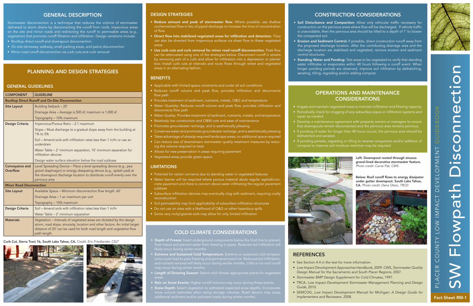
SW F
low
pat
h D
isco
nnec
tio
n
GENERAL DESCRIPTIONStormwater disconnection is a technique that reduces the volume of stormwater delivered to storm drains by disconnecting the runoff from roofs, impervious areas on the site and minor roads and redirecting the runoff to permeable areas (e.g., vegetation) that promote runoff filtration and infiltration. Design variations include:• Rooftop direct runoff and downspout disconnection• On-site (driveway, walkway, small parking areas, and patio) disconnection• Minor road runoff disconnection via curb cuts and curb removal
PL
AC
ER
CO
UN
TY
LO
W I
MP
AC
T D
EV
EL
OP
ME
NT
GU
IDE
BO
OK
Fact Sheet RM-1
DESIGN STRATEGIES
• Reduce amount and peak of stormwater flow. Where possible, use shallow unchannelized flow in lieu of piped discharge to increase the time of concentration of flow.
• Direct flow into stabilized vegetated areas for infiltration and detention. Flow can also be diverted from impervious surfaces via sheet flow to these vegetated areas.
• Use curb cuts and curb removal for minor road runoff disconnection. Peak flow can be attenuated using one of the strategies below: Disconnect runoff in streets by removing part of a curb and allow for infiltration into a depression or planter box; Install curb cuts at intervals and route flows through street and vegetated areas in an alternating fashion.
BENEFITS
• Applicable with limited space constraints and under all soil conditions• Reduces runoff volume and peak flow, provides infiltration and disconnects
flow path• Provides treatment of sediment, nutrients, metals, O&G and temperature• Water Quantity: Reduces runoff volume and peak flow, provides infiltration and
disconnects flow path• Water Quality: Provides treatment of sediment, nutrients, metals, and temperature• Relatively low construction and O&M cost and ease of maintenance• Promotes groundwater recharge, and is aesthetically pleasing• Conserves water and promotes groundwater recharge, and is aesthetically pleasing• Takes advantage of already-required landscape areas; no additional space required• Can reduce size of downstream stormwater quality treatment measures by reduc-
ing the volume required to treat• Allows for tree preservation in areas requiring pavement• Vegetated areas provide green space
LIMITATIONS
• Potential for vector concerns due to standing water in vegetated features• Water barrier will be required where porous material abuts regular asphalt/con-
crete pavement and there is concern about water infiltrating the regular pavement subbase
• Subsurface infiltration devices may eventually clog with sediment, requiring costly reconstruction
• Soil permeability may limit applicability of subsurface infiltration structures • Do not use on sites with a likelihood of O&G or other hazardous spills• Some very rocky/granite soils may allow for only limited infiltration
CONSTRUCTION CONSIDERATIONS • Soil Disturbance and Compaction: Allow only vehicular traffic necessary for
construction on the pervious areas where flow will be discharged. If vehicle traffic is unavoidable, then the pervious area should be tilled to a depth of 1’ to loosen the compacted soil.
• Erosion and Sediment Control: If possible, direct construction runoff away from the proposed discharge location. After the contributing drainage area and the discharge location are stabilized and vegetated, remove erosion and sediment control structures.
• Standing Water and Ponding: Test areas to be vegetated to verify that standing water infiltrates or evaporates within 48 hours following a runoff event. When longer ponding periods are observed, improve soil infiltration by dethatching, aerating, tilling, regrading and/or adding compost.
OPERATIONS AND MAINTENANCE CONSIDERATIONS
• Irrigate and maintain vegetated areas to maintain infiltration and filtering capacity.• Periodically check for clogging of any subsurface pipes or infiltration systems and
repair as needed.• Develop a maintenance agreement with property owners or managers to ensure
that downspouts remain disconnected and the pervious area remains pervious. • If ponding of water for longer than 48 hours occurs, the pervious area should be
dethatched and aerated. • If ponding persists, regrading or tilling to reverse compaction and/or addition of
compost to improve soil moisture retention may be required.
COLD CLIMATE CONSIDERATIONS • Depth of Freeze: Insert underground components below the frost line to prevent
frost heave and prevent water from freezing in pipes. Reduced soil infiltration will likely occur during winter months.
• Extreme and Sustained Cold Temperature: Extreme or sustained cold tempera-tures could lead to pipe freezing and permanent pool ice. Reduced soil infiltration, and nutrient removal will likely occur during winter months. Little or no roof runoff may occur during winter months.
• Length of Growing Season: Select cold climate appropriate plants for vegetated areas.
• Rain on Snow Events: Higher runoff volumes may occur during these events. • Snow Depth: Select vegetation to withstand expected snow depths. Incorporate
snow volume estimates when sizing storage volumes. Road deicers may cause additional sediment and/or pollutant loads during winter months.
GENERAL GUIDELINES
Left: Downspout routed through sinuous gravel-lined decorative stormwater feature. Photo credit: Carrie Pak, CWS.
Below: Roof runoff flows to energy dissipator under gutter downspout. South Lake Tahoe, CA. Photo credit: Dana Olson, TRCD
PLANNING AND DESIGN STRATEGIES
REFERENCES• See Section 4.4 in the text for more information.• Low Impact Development Approaches Handbook, 2009. CWS, Stormwater Quality
Design Manual for the Sacramento and South Placer Regions, 2007. • Stormwater BMP Design Supplement for Cold Climates, 1997.• TRCA, Low Impact Development Stormwater Management Planning and Design
Guide, 2010.• SEMCOG, Low Impact Development Manual for Michigan: A Design Guide for
Implementers and Reviewers. 2008.
COMPONENT GUIDELINE
Rooftop Direct Runoff and On-Site Disconnection
Site Layout Building Setback – 20’
Drainage Area – Average is 500 sf; maximum is 1,000 sf
Topography – 10% maximum
Design Criteria Impervious/Porous Ratio – 2:1 maximum
Slope – Must discharge to a gradual slope away from the building at 1% to 5%
Soil – Amend soils with infiltration rates less than 1 in/hr or use an underdrain
Water Table – 2’ minimum separation, 10’ minimum separation for infiltration devices
Design water surface elevation below the road subbase
Conveyance and Overflow
Level Spreading Device – Place a level spreading device (e.g., pea gravel diaphragm) or energy dissipating device (e.g., splash pad) at the downspout discharge location to distribute runoff evenly over the pervious area
Minor Road Disconnection
Site Layout Available Space – Minimum disconnection flow length: 60’
Drainage Area – 1 ac maximum per unit
Topography – 10% maximum
Design Criteria Soil – Amend soils with infiltration rates less than 1 in/hr
Water Table – 2’ minimum separation
Materials Vegetation – Intervals of vegetated areas are dictated by the design storm, road slope, sinuosity, location and other factors. An initial target distance of 20’ can be used for both road length and vegetative flow path length.
Curb Cut, Sierra Tract 1b, South Lake Tahoe, CA. Credit: Eric Friedlander, CSLT

Rai
nwat
er a
nd S
now
mel
t H
arve
stin
g
GENERAL DESCRIPTIONRainwater and snowmelt harvesting consists of collecting, conveying and storing rainfall and snowfall for future indoor and outdoor uses. The purpose of this harvest-ing is to collect high quality water to offset potable water demands. The rain or snow that falls upon an impervious surface (e.g. roof, driveway, or walkway) is collected and conveyed into a storage tank (e.g. rain barrel or cistern). With minimal pretreatment (e.g., gravity filtration or first-flush diversion), the captured rainwater or snowmelt can be used for outdoor non-potable water uses such as irrigation and pressure washing, or in the building to flush toilets or urinals.
PL
AC
ER
CO
UN
TY
LO
W I
MP
AC
T D
EV
EL
OP
ME
NT
GU
IDE
BO
OK
Fact Sheet RM-2
DESIGN STRATEGIES • Reduce volume of stormwater runoff by directing downspout to a rain barrel with
gravity distribution, routing multiple downspouts to a cistern and pump to reuse water, or collecting flows from impervious areas. Roof can also be used for snow storage, prior to snowmelt collection.
• Reduce potable water demands by using diverted and stored stormwater in lieu of potable water. Stored rain water and snowmelt can be used for non-potable uses, such as, landscaping, flushing toilets, and powerwashing.
• Reuse stormwater prior to pollutant contamination, as rainwater or snowmelt at the source is much cleaner than downstream runoff. Water from the roof or from low traffic areas is of higher quality and can be reused readily.
BENEFITS • Applicable with limited space constraints and under all soil conditions• Reduces runoff volume and peak flow and disconnects flow path• Does not add additional pollutants to runoff• Relatively low construction and O&M cost and ease of maintenance• Conserves water and promotes groundwater recharge• Managing stormwater runoff (including rainfall and snowmelt) and pollutants close
to the source can minimize costs of conveyance features• Cisterns can be combined with pervious parking areas • Rainwater harvesting systems can help reduce demand on municipal treated water
supplies• Reduced loads delay expansion of treatment and distribution systems, conserve
energy used for pumping and treating water and lower consumer water bills• It is estimated that these applications alone can reduce household municipal water
consumption by up to half• Where site designs permit, cisterns may be quite large, and shared by multiple
households, achieving economies of scale• Can be retrofitted into existing property
LIMITATIONS• Potential vector concerns should be addressed by using filter screens and keeping
storage tanks covered.• The stormwater volume/peak discharge rate benefits of cisterns and rain bar-
rels depend on the amount of storage available at the beginning of each storm. One rain barrel may provide a useful amount of water for garden irrigation, but it will have little effect on overall runoff volumes, especially if the entire tank is not drained in between storms.
• Greater effectiveness can be achieved by having more storage volume and by designing the system with a continuous discharge to an infiltration mechanism, so that there is always available volume for retention.
• Rain barrels and cisterns offer no primary pollutant removal benefits. However, this water is often cleaner than downstream runoff.
• The water collected is for nonpotable uses only.• Immediate use of harvested water is preferred to storage.
CONSTRUCTION CONSIDERATIONS • Soil Disturbance and Compaction: Allow only vehicular traffic necessary for
construction on the pervious areas where flow will be discharged. If vehicle traffic is unavoidable, then the pervious area should be tilled to a depth of 1’ to loosen the compacted soil.
• Erosion and Sediment Control: If possible, direct construction runoff away from the proposed discharge location. After the contributing drainage area and the discharge location are stabilized and vegetated, remove erosion and sediment control structures.
• Standing Water and Ponding: Test areas to be vegetated to verify that standing water infiltrates or evaporates within 48 hours following a runoff event. When longer ponding periods are observed, improve soil infiltration by dethatching, aerating, tilling, regrading and/or adding compost.
OPERATIONS AND MAINTENANCE CONSIDERATIONS
• Maintenance requirements for rainwater harvesting systems vary according to use • Systems that are used to provide supplemental irrigation water have relatively low
maintenance requirements, while systems designed for indoor uses have much higher maintenance requirements.
• Perform regular inspections every six months during the spring and fall seasons to keep leaf screens, eavestroughs and downspouts free of leaves and other debris; check screens and patch holes or gaps; clean and maintain first flush diverters and filters, especially those on drip irrigation systems; inspect and clean storage tank lids, paying special attention to vents and screens on inflow and outflow spigots; and replace damaged system components as needed.
• If screening is not sufficient to deter mosquitoes, use vegetable oil to smother larvae, or use mosquito dunks or pellets containing larvicide.
COLD CLIMATE CONSIDERATIONS • Depth of Freeze: Pipes are at risk for frost heave if they are above local frost
penetration depth. Frozen outlet pipes may be overwhelmed by first flush runoff. • Extreme and Sustained Cold Temperature: Extreme or sustained cold tempera-
tures could lead to pipe freezing and permanent pool ice . Little or no roof runoff may occur during winter months.
To prevent ice accumulation and damage during winter, place first-flush diverters or in-ground filters in a temperature controlled environment, bury below the local frost penetration depth or insulate or equip with heat tracing. Do the same with dual use cisterns and conveyance pipes leading to cisterns. Tank placement is recommended on the south side of the building. Insulate the tank outlet hose to the pump or services with mineral wool mat or molded insulation foam.
GENERAL GUIDELINES
PLANNING AND DESIGN STRATEGIES
COMPONENT GUIDELINE
Site Layout Available Space – Place storage tanks underground, indoors, on roofs, or adjacent to buildings, outside of County ROW
Building Setback – Make tanks water tight to avoid ponding or satura-tion of soils within 10’ of building foundations
Drainage Area – Dependent upon conveyance and storage tank sizing
Topography – Influences the placement of the storage tank and design of the distribution and overflow systems
Design Criteria Head – Locate rain barrels or above ground cisterns with gravity distri-bution systems up-gradient from irrigated areas
Soil – Locate underground cisterns in native, rather than fill soil for stability
Utility/Tree Clearance – Utilities may constrain the location of under-ground storage tanks
Water Table – Can be used under various depth to water ranges
Pretreatment Pretreat runoff to remove debris, dust, leaves, and other debris
Use Leaf and mosquito screens (1 mm mesh size), first-flush diverter, or in-tank filter
Use settling compartment for tanks over 2,500 gallons
Conveyance and Overflow
Rain barrels use head and gravity to feed hoses via a tap and spigot
Use a water pump for underground cisterns. Indoor systems usually require a pump, pressure tank, back-up water supply line and backflow preventer
Include an overflow system in the design (outflow pipe = inflow pipe size)
Storage Tank size varies based on rainfall and snowfall frequencies and totals, end-use of water, the catchment surface area, aesthetics, and budget
Storage tanks range in size from rain barrels for residential land uses (typically 50 to 100 gallons), to large cisterns (200-400 gallons) for industrial, commercial and institutional land uses
Use opaque, potable or food-grade structurally sound materials to construct storage tanks
Install tanks in locations where native soils or building structures can support the load from the stored water
Childproof rain barrels and cisterns and seal against mosquitoes
Materials Roof – Metal roofs are recommended
Downspouts and Eavestroughs – Materials include PVC pipe, vinyl, aluminum and galvanized steel
Do not use lead as solder
REFERENCES• See Section 4.4 in the text for more information.• KJ, Truckee Meadows Structural Control Design Manual, 2007.• CWS, LID Approaches Handbook, 2009.• Stormwater Quality Design Manual for the Sacramento and South Placer
Regions, 2007.• TRCA, LID Stormwater Management Planning and Design Guide, 2010.• CWP, Stormwater BMP Design Supplement for Cold Climates, 1997.• MAPC, Mass LID Toolkit, 2007.• CASQA, California Stormwater Best Management Practice Handbook,
New Development and Redevelopment, 2003.• UDFCD, Best Management Practices, 1999.
Left: TCES Rainfwater Harvesting System with UV, Photo Credit: Heather Segale, TERC
Below: Water Capture System, Credit: Heather Segale, TERC

Infil
trat
ion
Tren
ch a
nd D
ry W
ell
GENERAL DESCRIPTIONDry wells and infiltration trenches store water in the void (pore) space between crushed stone or gravel where the water slowly percolates downward into the sub-soil. An overflow outlet is needed for runoff from large storms that cannot be fully infiltrated by the trench or dry well.
PL
AC
ER
CO
UN
TY
LO
W I
MP
AC
T D
EV
EL
OP
ME
NT
GU
IDE
BO
OK
Fact Sheet RM-3
DESIGN STRATEGIES • Reduce peak discharge rate and total runoff volume by infiltrating a portion of
stormwater generated on-site, which will result in modest groundwater recharge.
BENEFITS • Reduce stormwater runoff volume, including most of the runoff from small frequent
storms• Reduce peak discharge rates by retaining the first flush of stormwater runoff and
creating longer flow paths for runoff• Reduce the size of more expensive downstream stormwater management structures
LIMITATIONS• Potential vector concerns due to standing water during infiltration• Cannot receive untreated stormwater runoff, except roof- top runoff. Pretreatment
is necessary to prevent premature failure that results from fine sediment, and to pre-vent potential groundwater contamination due to nutrient, salts, and hydrocarbons
• Can not be used to treat runoff from portions of the site that are not stabilized, and might result in erosion
• Rehabilitation of failed infiltration trenches requires complete reconstruction• Difficult to use in slowly permeable soils or in fill areas
CONSTRUCTION CONSIDERATIONS • Soil Disturbance and Compaction: Before site work begins, clearly mark areas
for dry well pits. Only allow vehicular traffic used for construction close to the strip.
• Erosion and Sediment Control: Do not use infiltration practices as a sediment control device during construction. Direct construction runoff away from the pro-posed filter strip site. After the site is vegetated, remove erosion and sediment control structures.
OPERATIONS AND MAINTENANCE CONSIDERATIONS
• After construction, inspect after every major storm for the first few months to ensure stabilization and proper function.
• On a monthly basis, remove sediment and oil/grease from pretreatment devices, overflow structures, and the surface of infiltration trenches.
• Semi-annually, check observation wells 3 days after a major storm. Failure to percolate within this time period indicates clogging.
• Semi-annually, inspect pretreatment devices and diversion structures for structural damage.
• If ponding occurs on the surface of an infiltration trench, remove and replace the topsoil or first layer of stone and top layer of filter fabric.
• Upon failure, perform total rehabilitation of the trench to maintain a storage capacity within 2/3 of the design treatment volume and 72-hour exfiltration rate.
COLD CLIMATE CONSIDERATIONS • Depth of Freeze: Pipes are at risk for freezing and/or frost heave if they are above
local frost penetration depth. Frozen outlet pipes may be overwhelmed by first flush runoff.
• Extreme and Sustained Cold Temperature: Extreme or sustained cold tempera-tures could lead to pipe freezing and permanent pool ice. Reduced soil infiltration, and nutrient removal will likely occur during winter months.
• Rain on Snow Events: Higher runoff volumes may occur during these events. To prevent ice accumulation and damage during winter, place conveyance pipes below the local frost penetration depth and/or insulate pipes. Increase depth of feature to keep stored runoff below frost line. Incorporate snow volume estimates when sizing storage volumes. Due to increased sediment and pollutant loads do not treat snow that has been exposed to deicers without pretreatment.
GENERAL GUIDELINES
PLANNING AND DESIGN STRATEGIES
REFERENCES• See Section 4.4 in the text for more information.• KJ,Truckee Meadows Structural Control Design Manual, 2007.• CWS, LID Approaches Handbook, 2009.• TRCA, LID Stormwater Management Planning and Design Guide, 2010.• CWP, Stormwater BMP Design Supplement for Cold Climates, 1997.• Massachusetts LID Toolkit, 2007.• TRCD and NTCD, Drip Line Infiltration Trench, 2006.
COMPONENT GUIDELINE
Site Layout Building Setback – 20’ minimum distanceDrainage Area – <5ac maximum per unitTopography – 5% maximum contributing slopeInstall outside of County ROW
Design Criteria
Soil – Infiltration rates of existing site soils must be a minimum of 0.5 in/hr and a maximum of 2.4 in/hr, or use an underdrainSlope – do not apply on slopes greater than 20 percentUtility/Tree Clearance – do not locate under tree drip lines; Consider remov-ing all trees within 10’Water Table – 10’ minimum separationWellhead Protection – 100’ setback from potable water wellsMaximum trench depth recommended is 10”The maximum depth of the stone in the dry well pit is 5’
Infiltration Rate
Drill borings to determine infiltration rate (one boring at each dry well, two borings at each infiltration trench), with additional borings at 50 feet intervalsDetermine the infiltrative capacity using a double-ring infiltrometer Base trench/drywell sizing on the slowest rateDo not use trenches or dry wells where soils are >30% clay or >40% silt clay
Pretreatment Remove sediment prior to treatment to prevent reduction of infiltration capacityVegetated filter strip, Vegetated swale, and Bioretention are all suitable pretreatment measures
Conveyance and Overflow
Inlet pipes are typically perforated pipe connected to a standard non-perforated pipe or eavestroughThe overflow outlet can be the perforated pipe inlet that backs up and discharges to a splash pad and pervious area at grade or can be a pipe that is at the top of the gravel layer and is connected to a storm sewerOutlet pipes must have capacity equal to or greater than the inlet.Use distribution pipes with perforations of 0.5” that are capped at least 1 foot short of the wall of the trench or well
Materials The dry well should be filled with uniformly-graded, washed 2” diameter stone with a 40% void capacityTrench should be filled with washed 3/4” to 1 1/2” drain rockAdd optional horizontal layer of geotextile fabric layer 2”-6” below the trench surface to reduce sedimentNon-woven filter cloth should be used to line the trench to prevent the pore space between the stones from being blocked by surrounding native materialTrim tree roots flush with the trench sides in order to prevent puncturing or tearing the filter fabricUse an HDPE underdrain pipe that has a perforated, smooth interior, and minimum inside diameter of 4”. Perforated pipe should run lengthwise through the dry wellInstall containment borders using pressure treated lumber, recycled compos-ites, brick, stone, cobble, or other landscape edging material
Credit: TRCA, 2010
Dry Rock Dry Well Photo Credit: Dana Olson, TRCD
Driveway runoff conveyed by slotted channel drain to infiltration system Photo Credits: Dana Olson, TRCD
Sloped driveway conveys runoff to infiltration trench
Infiltration Trench contoured along house Photo Credit: TRCA, 2010

GENERAL DESCRIPTIONBioretention areas (raingardens, tree pits, planters, and curb extensions) are planted depressions that store and filter rainwater to enhance water quality. Stormwater run-off flows into the cell and slowly percolates through the soil (which acts as a filter) and into the groundwater; some of the water is also taken up by the plants. Bioretention areas are usually designed to allow shallow ponding, with an overflow outlet to pre-vent flooding during heavy storms.
PL
AC
ER
CO
UN
TY
LO
W I
MP
AC
T D
EV
EL
OP
ME
NT
GU
IDE
BO
OK
Fact Sheet RM-4
DESIGN STRATEGIES • Provide water quality treatment through filtration: Bioretention areas treat storm-
water runoff by passing it through a mixture of sand, soil, and organic material.• Increase groundwater recharge through infiltration: Bioretention areas allow
infiltration to occur over an extended time period to enhance overall infiltration. • Reduce peak discharge rates and total runoff volume: Bioretention areas may
be used to store excess stormwater when the downstream infiltration system has been surcharged.
• Improve site landscaping: Bioretention areas are typically installed in commer-cial, institutional, and residential sites in spaces that are traditionally pervious and landscaped.
BENEFITS • Properly designed cells remove suspended solids, metals, and nutrients, and can
infiltrate an inch or more of rainfall.• Can provide excellent pollutant removal and recharge for the “first flush” of storm-
water runoff • Increase groundwater recharge as compared to a conventional “pipe and pond”
approach • Low-tech, decentralized bioretention areas are also less costly to design, install,
and maintain than conventional stormwater technologies that treat runoff at the end of the pipe.
• Bioretention areas enhance the landscape in a variety of ways: they improve the appearance of developed sites, provide wind breaks, absorb noise, provide wild-life habitat, and reduce the urban heat island effect.
LIMITATIONS• Potential vector concerns due to standing water in vegetated features• Not suitable for locations where the seasonally high groundwater table is near the
surface• Clogging may be a problem in areas with high sediment loads in runoff• Vegetation may require irrigation
CONSTRUCTION CONSIDERATIONS • Divert runoff (other than necessary irrigation) during the period of vegetation
establishment. Where runoff diversion is not possible, cover graded, seeded, and/or planted areas with suitable erosion control materials.
• For planters flush with the surrounding landscape, install sediment controls (staked straw wattles) around the planter to prevent high sediment loads from entering during construction activities.
• Focus on erosion and sediment control, materials elevation, and landscape stabi-lization during Construction Inspection.
OPERATIONS AND MAINTENANCE CONSIDERATIONS
• Inspect pretreatment devices and bioretention cells regularly for sediment build-up, structural damage, and standing water.
• Inspect soil and repair eroded areas monthly. Re-mulch void areas as needed. Remove litter and debris monthly.
• Treat diseased vegetation as needed. Remove and replace dead vegetation twice per year.
• Remove invasive species as needed to prevent these species from spreading into the bioretention area.
• Replace mulch every two years, in the early spring.• Upon failure, excavate bioretention area, scarify bottom and sides, replace filter
fabric and soil, replant, and mulch.
COLD CLIMATE CONSIDERATIONS • Depth of Freeze: Pipes are at risk for freezing and/or frost heave if they are
above local frost penetration depth. Frozen outlet pipes may be overwhelmed by first flush runoff.
• Extreme and Sustained Cold Temperature: Extreme or sustained cold tem-peratures could lead to pipe freezing and permanent pool ice. Reduced soil infiltration, and nutrient removal will likely occur during winter months.
• Length of Growing Season: Select cold climate appropriate plants for veg-etated areas.
• Rain on Snow Events: Higher runoff volumes may occur during these events.• Snow Depth: Select vegetation to withstand expected snow depths.To prevent ice accumulation and damage during winter, place conveyance pipes below the local frost penetration depth and/or insulate pipes. Size facilities for coldest temperature removal rates (decreased biological activity, settling etc.), expect enhanced removal during non-winter months. Incorporate snow volume estimates when sizing storage volumes. Road deicers may cause additional sediment and/or pollutant loads during winter months.
GENERAL GUIDELINES
PLANNING AND DESIGN STRATEGIES
REFERENCES• See Section 4.4 in the text for more information.• KJ, Truckee Meadows Structural Control Design Manual, 2007.• CWS, LID Approaches Handbook, 2009.• Stormwater Quality Design Manual for the Sacramento and South Placer
Regions, 2007.• TRCA, LID Stormwater Management Planning and Design Guide, 2010.• CWP, Stormwater BMP Design Supplement for Cold Climates, 1997.• CASQA, California Stormwater Best Management Practice Handbook,
New Development and Redevelopment, 2003.• UDFCD, Best Management Practices, 1999.
COMPONENT GUIDELINE
Site Layout Available Space – Minimum dimensions 15’ wide by 40’ longBuilding Setback – If no impermeable liner, minimum 10’ setbackDrainage Area – Typically 1,000 sf to 1 acTopography – Contributing slopes between 1 to 5%
Design Criteria Freeboard – Allow 3” of freeboard above ponding depth to prevent flooding to adjacent parking areasHead – 3’ minimum vertical distance from invert to inflow pointInlets and outlets should be located as far apart as possibleSoil – Infiltration rates of existing site soils must be a minimum of 0.5 in/hr and a maximum of 2.4 in/hr, or use an underdrainSlope – Do not apply on slopes greater than 20 percentWater Table – Minimum 5’ separationWellhead Protection – Minimum separation of 100’ from potable water supply wells
Pretreatment Pre-treatment measures include, grass filter strip, and vegetated swaleMay also be used to infiltrate overflow from infiltration trench/drywell or rainwater harvesting
Conveyance and Overflow
The inflow conveyance may consist of, downspout, sheet flow, curb cuts, covered drain, or pop-up emitters.Overflow can either be diverted by:• Sizing curb openings to capture only the water quality volume while
higher flows remain in the gutter• Utility landscaping type inlets or standpipes with trash guards as
overflow devices• Using a pre-treatment chamber with a weir design that limits flow to
the filter bed area
Storage Snow can be stored in shallow depressionsWater can be stored in pool areas
Materials Vegetation – Planting plan generally includes one tree or shrub per 50 s.f. of bioretention area, and at least 3 species each of native herbaceous perennials, shrubs, and trees. Select plants that tolerate intermittent flooding, occasionally saline conditions, and extended dry periods.Filter medium – 85% sand, 10% fines, 5% organic matterMulch layer – Shredded hardwood or bark Geotextile: Should be woven monofilament or non-woven needle punched fabrics. Woven slit film and non-woven heat bonded fabrics should not be used as they are prone to clogging.Gravel: Washed 2” diameter stone should be used to surround the underdrain and for the gravel drainage layer
Bio
rete
ntio
n
POLLU- TANT
% REMOVAL
TSS 75-90
TP 70-80
TN 65-80
ZINC 75-80
LEAD 75-80
ORGANICS 75-90
BACTERIA 75-90
Credits: Carrie Pak, CWS
Left: Flow-through-Planter Photo Credit: Ed Armstrong, Foothill
Right: Rain Garden Photo Credit: Dana Olson, TRCD
Left: Flow through planter
Right: Rain garden

GENERAL DESCRIPTIONVegetated filter strips (buffer strips and grass filter strips) are gently sloping, densely vegetated areas that treat runoff as sheet flow from adjacent impervious areas. They slow runoff velocity, filter out suspended sediment, provide some infiltration into underlying soils and are effective as a pretreatment practice. Vegetation may be comprised of a variety of trees, shrubs and groundcovers to add aesthetic value as well as water quality benefits. Vegetated Filter Strips provide a convenient area for snow storage and treatment, and are particularly valuable due to their capacity for snowmelt infiltration.
PL
AC
ER
CO
UN
TY
LO
W I
MP
AC
T D
EV
EL
OP
ME
NT
GU
IDE
BO
OK
Fact Sheet RM-5
DESIGN STRATEGIES • Reduce peak discharge rate and total runoff volume: Vegetated filter strips
redirect stormwater from pervious areas and slow the flow due to increased rough-ness in the vegetation.
• Provide snow storage areas: Grass filter strips provide areas where snow can be stored.
BENEFITS • Provide runoff pretreatment by trapping, filtering and infiltrating particulates
and associated pollutants. Effectiveness depends largely on the quantity of water treated, the slope and length of the filter strip, the type of vegetation, and the soil infiltration rate
• Reduce runoff velocities and increase the time of concentration as compared to channelized flow, resulting in a reduction of erosion and peak discharge rates
LIMITATIONS• Because filter strips infiltrate runoff to groundwater, they could be inappropriate at
stormwater “hotspots” (such as gas stations) with higher potential pollutant loads. Combine them with other LID features to ensure adequate treatment of polluted runoff prior to discharge.
• Channelization and premature failure may result from poor design, imprecise con-struction, or lack of maintenance. Proper design requires a great deal of finesse, and slight problems in the construction, such as improper grading, can render the practice less effective in terms of pollutant removal.
• Filter strips have low removal rates for nutrients, so use them in conjunction with other LID features.
• Filter strips often require lots of space, making them often infeasible in urban environments where land prices are high.
• Vegetation may require irrigation.
CONSTRUCTION CONSIDERATIONS • Soil Disturbance and Compaction: Clearly show the limits of disturbance on all
construction drawings. Before site work begins, clearly mark areas for filter strips and protect them by using acceptable signage and silt fencing. Isolate construc-tion vehicular traffic so that other traffic does not come near the filter strip.
• Erosion and Sediment Control: Direct construction runoff away from the pro-posed filter strip site. If used for sediment control during construction, regrade and revegetate after construction is finished.
OPERATIONS AND MAINTENANCE CONSIDERATIONS
• Inspect level spreader monthly and remove built-up sediment.• Inspect vegetation monthly for rills and gullies and correct. Fill any depressions or
channels. Seed or sod bare areas.• In the year following construction, inspect the filter strip regularly to ensure that
grass has established. If not, replace with an alternative species. Allow natural succession by native grasses and shrubs if it occurs.
• Mow grass, as rarely as 2-3 times per year, to maintain 4” to 6” of dense grass cover. Grass clippings should be collected and composted elsewhere. Provide a minimum of fertilizer only when necessary. Mow when the soil is dry and firm to prevent rutting.
• Semi-annually, remove sediment that has accumulated to prevent berms or channels.
COLD CLIMATE CONSIDERATIONS • Depth of Freeze: Pipes are at risk for freezing and/or frost heave if they are above
local frost penetration depth. Frozen outlet pipes may be overwhelmed by first flush runoff.
• Extreme and Sustained Cold Temperature: Extreme or sustained cold tempera-tures could lead to pipe freezing and permanent pool ice. Reduced soil infiltration, and nutrient removal will likely occur during winter months.
• Length of Growing Season: Select cold climate appropriate plants for vegetated areas.
• Rain on Snow Events: Higher runoff volumes may occur during these events• Snow Depth: Select vegetation to withstand expected snow depths.Install pipes components below the frost line to prevent frost heave and preventing water from freezing in pipes. Size facilities for coldest temperature removal rates (decreased biological activity, settling etc.), expect enhanced removal during non-winter months. Road deicers may cause additional sediment and/or pollutant loads during winter months.
GENERAL GUIDELINES
PLANNING AND DESIGN STRATEGIES
REFERENCES• See Section 4.4 in the text for more information.• KJ, Truckee Meadows Structural Control Design Manual, 2007.• CWS, LID Approaches Handbook, 2009.• Stormwater Quality Design Manual for the Sacramento and South Placer
Regions, 2007.• TRCA, LID Stormwater Management Planning and Design Guide, 2010.• CWP, Stormwater BMP Design Supplement for Cold Climates, 1997.• CASQA, California Stormwater Best Management Practice Handbook,
New Development and Redevelopment, 2003.• UDFCD, Best Management Practices, 1999.
COMPONENT GUIDELINE
Site Layout Available Space – Ratio of drainage area and footprint = 6:1. Minimum 20’ in direction of flow, 60’ maximum for impervious surfaces, and 100’ maximum for pervious surfaces
Building Setback – 10’ minimum separation
Design Criteria Soil – All soil types
Slope – Specify slopes should be between 1% and 15%, though slopes less than 5% are preferred. Design the top and toe of the slope to be as flat as possible.
Water Table – Minimum 3’ separation
Sheet flow must be maintained across strips
Vegetation – Requires dense vegetation minimum of 2” to 4” tall
Normal velocity should be <1.0 ft/s for design flow, with maximum permissible velocity of 3.0 ft/s for peak discharge during 10-yr storm
Pretreatment Functions well as a pretreatment device
Conveyance and Overflow
Use a cement level spreader or pea gravel diaphragm at the top of the slope.
Filter strips can be designed with a pervious berm of sand and gravel at the toe of the slope. This feature provides an area for shallow pond-ing at the bottom of the filter strip. Runoff ponds behind the berm and gradually flows through outlet pipes in the berm. The volume ponded behind the berm should be equal to the water quality volume.
Storage Snow can be stored on feature
Materials Soil – If soils on the filter strip site are highly compacted, or of such low fertility that vegetation cannot become established, they should be tilled to a depth of 1’ and amended with compost to achieve an organic content of 8 to 15% by weight or 30 to 40% by volume.
Vegetation – Select vegetation that can withstand calculated flow velocities, and both wet and dry periods. Also consider depth to groundwater and choose facultative wetland species if appropriate.
Veg
etat
ed F
ilter
Str
ip
Vegetated filter strip traffic island Photo Credit: Carrie Pak, CWS
Vegetated filter strip Photo Credit: Carrie Pak, CWS
Vegetated filter strip profile Credit: Carrie Pak, CWS
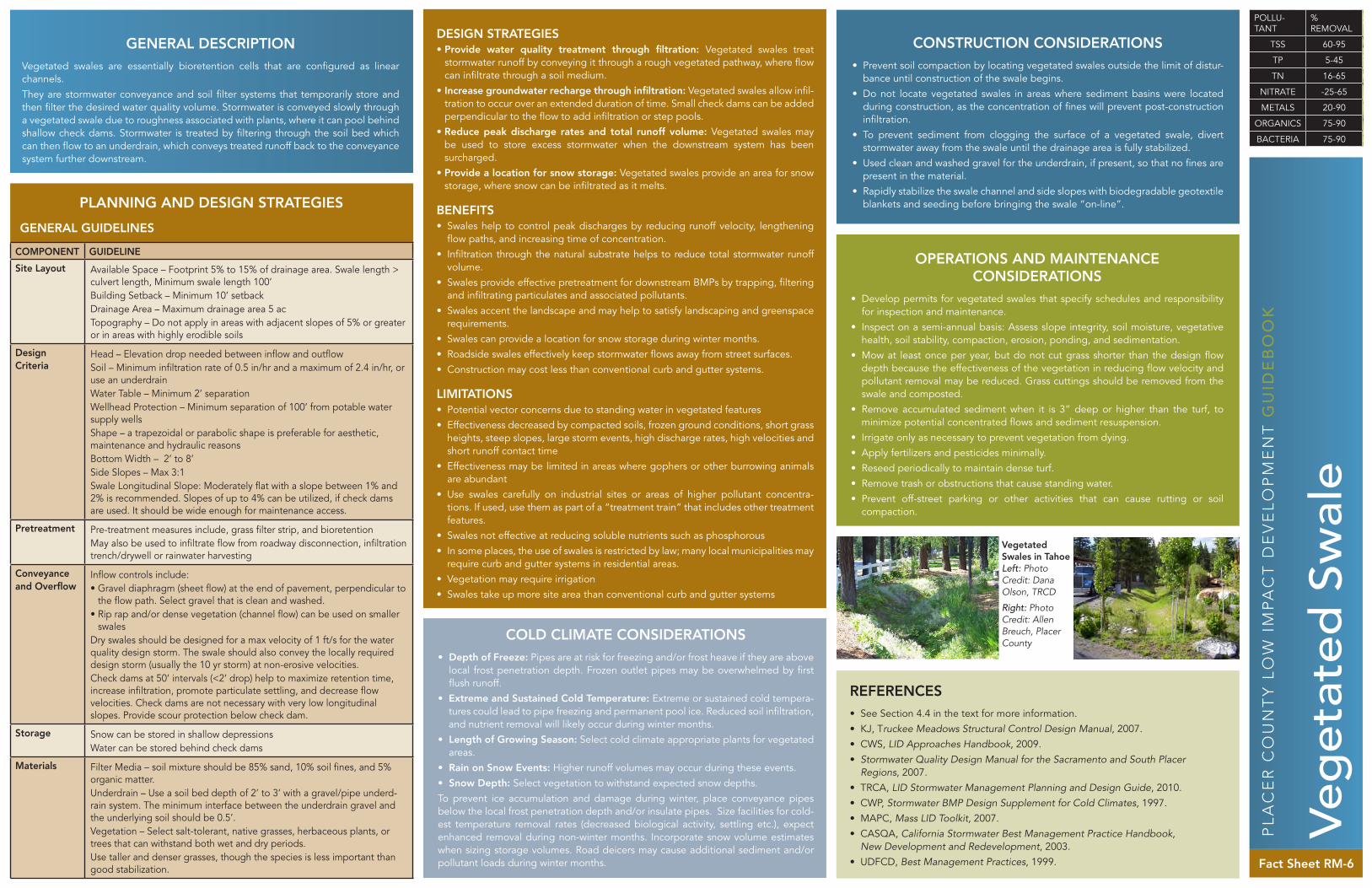
GENERAL DESCRIPTIONVegetated swales are essentially bioretention cells that are configured as linear channels.They are stormwater conveyance and soil filter systems that temporarily store and then filter the desired water quality volume. Stormwater is conveyed slowly through a vegetated swale due to roughness associated with plants, where it can pool behind shallow check dams. Stormwater is treated by filtering through the soil bed which can then flow to an underdrain, which conveys treated runoff back to the conveyance system further downstream.
PL
AC
ER
CO
UN
TY
LO
W I
MP
AC
T D
EV
EL
OP
ME
NT
GU
IDE
BO
OK
Fact Sheet RM-6
DESIGN STRATEGIES • Provide water quality treatment through filtration: Vegetated swales treat
stormwater runoff by conveying it through a rough vegetated pathway, where flow can infiltrate through a soil medium.
• Increase groundwater recharge through infiltration: Vegetated swales allow infil-tration to occur over an extended duration of time. Small check dams can be added perpendicular to the flow to add infiltration or step pools.
• Reduce peak discharge rates and total runoff volume: Vegetated swales may be used to store excess stormwater when the downstream system has been surcharged.
• Provide a location for snow storage: Vegetated swales provide an area for snow storage, where snow can be infiltrated as it melts.
BENEFITS • Swales help to control peak discharges by reducing runoff velocity, lengthening
flow paths, and increasing time of concentration.• Infiltration through the natural substrate helps to reduce total stormwater runoff
volume.• Swales provide effective pretreatment for downstream BMPs by trapping, filtering
and infiltrating particulates and associated pollutants. • Swales accent the landscape and may help to satisfy landscaping and greenspace
requirements.• Swales can provide a location for snow storage during winter months.• Roadside swales effectively keep stormwater flows away from street surfaces.• Construction may cost less than conventional curb and gutter systems.
LIMITATIONS• Potential vector concerns due to standing water in vegetated features• Effectiveness decreased by compacted soils, frozen ground conditions, short grass
heights, steep slopes, large storm events, high discharge rates, high velocities and short runoff contact time
• Effectiveness may be limited in areas where gophers or other burrowing animals are abundant
• Use swales carefully on industrial sites or areas of higher pollutant concentra-tions. If used, use them as part of a “treatment train” that includes other treatment features.
• Swales not effective at reducing soluble nutrients such as phosphorous• In some places, the use of swales is restricted by law; many local municipalities may
require curb and gutter systems in residential areas.• Vegetation may require irrigation• Swales take up more site area than conventional curb and gutter systems
CONSTRUCTION CONSIDERATIONS • Prevent soil compaction by locating vegetated swales outside the limit of distur-
bance until construction of the swale begins.• Do not locate vegetated swales in areas where sediment basins were located
during construction, as the concentration of fines will prevent post-construction infiltration.
• To prevent sediment from clogging the surface of a vegetated swale, divert stormwater away from the swale until the drainage area is fully stabilized.
• Used clean and washed gravel for the underdrain, if present, so that no fines are present in the material.
• Rapidly stabilize the swale channel and side slopes with biodegradable geotextile blankets and seeding before bringing the swale “on-line”.
OPERATIONS AND MAINTENANCE CONSIDERATIONS
• Develop permits for vegetated swales that specify schedules and responsibility for inspection and maintenance.
• Inspect on a semi-annual basis: Assess slope integrity, soil moisture, vegetative health, soil stability, compaction, erosion, ponding, and sedimentation.
• Mow at least once per year, but do not cut grass shorter than the design flow depth because the effectiveness of the vegetation in reducing flow velocity and pollutant removal may be reduced. Grass cuttings should be removed from the swale and composted.
• Remove accumulated sediment when it is 3” deep or higher than the turf, to minimize potential concentrated flows and sediment resuspension.
• Irrigate only as necessary to prevent vegetation from dying.• Apply fertilizers and pesticides minimally.• Reseed periodically to maintain dense turf.• Remove trash or obstructions that cause standing water.• Prevent off-street parking or other activities that can cause rutting or soil
compaction.
COLD CLIMATE CONSIDERATIONS • Depth of Freeze: Pipes are at risk for freezing and/or frost heave if they are above
local frost penetration depth. Frozen outlet pipes may be overwhelmed by first flush runoff.
• Extreme and Sustained Cold Temperature: Extreme or sustained cold tempera-tures could lead to pipe freezing and permanent pool ice. Reduced soil infiltration, and nutrient removal will likely occur during winter months.
• Length of Growing Season: Select cold climate appropriate plants for vegetated areas.
• Rain on Snow Events: Higher runoff volumes may occur during these events. • Snow Depth: Select vegetation to withstand expected snow depths.To prevent ice accumulation and damage during winter, place conveyance pipes below the local frost penetration depth and/or insulate pipes. Size facilities for cold-est temperature removal rates (decreased biological activity, settling etc.), expect enhanced removal during non-winter months. Incorporate snow volume estimates when sizing storage volumes. Road deicers may cause additional sediment and/or pollutant loads during winter months.
GENERAL GUIDELINES
PLANNING AND DESIGN STRATEGIES
REFERENCES• See Section 4.4 in the text for more information.• KJ, Truckee Meadows Structural Control Design Manual, 2007.• CWS, LID Approaches Handbook, 2009.• Stormwater Quality Design Manual for the Sacramento and South Placer
Regions, 2007.• TRCA, LID Stormwater Management Planning and Design Guide, 2010.• CWP, Stormwater BMP Design Supplement for Cold Climates, 1997.• MAPC, Mass LID Toolkit, 2007.• CASQA, California Stormwater Best Management Practice Handbook,
New Development and Redevelopment, 2003.• UDFCD, Best Management Practices, 1999.
COMPONENT GUIDELINE
Site Layout Available Space – Footprint 5% to 15% of drainage area. Swale length > culvert length, Minimum swale length 100’Building Setback – Minimum 10’ setbackDrainage Area – Maximum drainage area 5 acTopography – Do not apply in areas with adjacent slopes of 5% or greater or in areas with highly erodible soils
Design Criteria
Head – Elevation drop needed between inflow and outflowSoil – Minimum infiltration rate of 0.5 in/hr and a maximum of 2.4 in/hr, or use an underdrainWater Table – Minimum 2’ separationWellhead Protection – Minimum separation of 100’ from potable water supply wellsShape – a trapezoidal or parabolic shape is preferable for aesthetic, maintenance and hydraulic reasonsBottom Width – 2’ to 8’Side Slopes – Max 3:1Swale Longitudinal Slope: Moderately flat with a slope between 1% and 2% is recommended. Slopes of up to 4% can be utilized, if check dams are used. It should be wide enough for maintenance access.
Pretreatment Pre-treatment measures include, grass filter strip, and bioretentionMay also be used to infiltrate flow from roadway disconnection, infiltration trench/drywell or rainwater harvesting
Conveyance and Overflow
Inflow controls include:• Gravel diaphragm (sheet flow) at the end of pavement, perpendicular to
the flow path. Select gravel that is clean and washed.• Rip rap and/or dense vegetation (channel flow) can be used on smaller
swalesDry swales should be designed for a max velocity of 1 ft/s for the water quality design storm. The swale should also convey the locally required design storm (usually the 10 yr storm) at non-erosive velocities.Check dams at 50’ intervals (<2’ drop) help to maximize retention time, increase infiltration, promote particulate settling, and decrease flow velocities. Check dams are not necessary with very low longitudinal slopes. Provide scour protection below check dam.
Storage Snow can be stored in shallow depressionsWater can be stored behind check dams
Materials Filter Media – soil mixture should be 85% sand, 10% soil fines, and 5% organic matter.Underdrain – Use a soil bed depth of 2’ to 3’ with a gravel/pipe underd-rain system. The minimum interface between the underdrain gravel and the underlying soil should be 0.5’.Vegetation – Select salt-tolerant, native grasses, herbaceous plants, or trees that can withstand both wet and dry periods.Use taller and denser grasses, though the species is less important than good stabilization.
Veg
etat
ed S
wal
e
POLLU- TANT
% REMOVAL
TSS 60-95
TP 5-45
TN 16-65
NITRATE -25-65
METALS 20-90
ORGANICS 75-90
BACTERIA 75-90
Vegetated Swales in Tahoe Left: Photo Credit: Dana Olson, TRCD
Right: Photo Credit: Allen Breuch, Placer County

GENERAL DESCRIPTIONPermeable paving allows rainwater to percolate through the paving and into the ground before it runs off. This approach reduces stormwater runoff volumes and minimizes the pollutants introduced into stormwater runoff from parking areas. All permeable paving systems consist of a durable, load bearing, pervious surface over-lying a crushed stone base that stores rainwater before it infiltrates into the underlying soil. Permeable paving techniques include porous asphalt, pervious concrete, paving stones, and manufactured “grass pavers” made of concrete or plastic. Permeable paving may be used for walkways, patios, plazas, driveways, parking stalls, and over-flow parking areas.
PL
AC
ER
CO
UN
TY
LO
W I
MP
AC
T D
EV
EL
OP
ME
NT
GU
IDE
BO
OK
Fact Sheet RM-7
DESIGN STRATEGIES • Provide water quality treatment through filtration: Permeable pavement acts as
a filter to remove particulate matter from stormwater.• Increase groundwater recharge through infiltration: Permeable pavement allows
infiltration to occur. • Reduce peak discharge rates and total runoff volume: The portion of flow that is
filtered through the permeable pavement will reduce the overall amount of storm-water flowing downstream.
• Infiltrate into storage areas: Permeable pavement can be used to infiltrate storm-water into underground cisterns or storage areas (infiltration galleries)
BENEFITS • Permeable paving can infiltrate as much as 70% to 80% of annual rainfall.• Porous pavement can reduce peak discharge rates significantly by diverting storm-
water into the ground and away from the pipe-and-pond stormwater management system.
• Grass pavers can improve site appearance by providing vegetation.• Porous paving increases effective developable area on a site because portions of
the stormwater management system are located underneath the paved areas, and the infiltration provided by permeable paving can significantly reduce the need for large stormwater management structures on a site.
LIMITATIONS• Typically not to be applied on streets with speeds greater than 30 mph or streets
with high traffic loads• Permeable paving can be prone to clogging from sand and fine sediments that fill
void spaces and the joints between pavers. • In cold climates, the potential for frost heave may be a concern for the use of
permeable paving. Some design manuals recommend excavating the base course to below the frost line, but this may not be necessary in rapidly permeable soils. In addition, the dead air and void spaces in the base course provide insulation so that the frost line is closer to the surface.
• Snow plows can catch the edge of grass pavers and some paving stones. Rollers should be attached to the bottom edge of a snowplow to prevent this problem.
• Permeable paving should not receive stormwater from other drainage areas, espe-cially any areas that are not fully stabilized.
CONSTRUCTION CONSIDERATIONS • Fully protect treatment area throughout construction• Compact aggregate with a minimum 10 ton steel drum• Avoid extremely high and low temperatures during construction• Test materials onsite• Consult industry reps should be consulted for specifications on batching and
placement• Construct as one of the last items to be built on a development site, after most
heavy construction vehicles are finished and after the majority of the landscaping work is completed.
OPERATIONS AND MAINTENANCE CONSIDERATIONS
• The blade of the snow plow should be set 1 inch higher than normal when plow-ing on these surfaces. When contamination is an issue, do not direct snow piles and melt toward these systems.
• Post signs identifying porous pavement areas• Minimize use of salt or sand during winter months• Keep landscaped areas well-maintained and prevent soil from being transported
onto the pavement• Clean the surface using vacuum sweeping machines• For paving stones, periodically add joint material (sand) to replace material that
has been transported• Monitor regularly to ensure that the paving surface drains properly after storms• Do not reseal or repave with impermeable materials• Inspect the surface annually for deterioration• Grass pavers may require periodic reseeding to fill in bare spots• Clean out drainage pipes and structures within or draining to the subsurface bed-
ding beneath porous pavement at regular intervals
COLD CLIMATE CONSIDERATIONS • Depth of Freeze: Pipes are at risk for freezing and/or frost heave if they are
above local frost penetration depth. Frozen outlet pipes may be overwhelmed by first flush runoff.
• Extreme and Sustained Cold Temperature: Extreme or sustained cold tem-peratures could lead to pipe freezing and permanent pool ice. Reduced soil infiltration, and nutrient removal will likely occur during winter months.
• Rain on Snow Events: Higher runoff volumes may occur during these events.To prevent frost heave, increase depth of aggregate base to keep stored runoff below frost line. Incorporate snow volume estimates when sizing storage volumes. Do not use road deicers on permeable paving or allow contact with runoff that has been exposed to road deicers, to prevent clogging from added sediment load. Raise blades or add rollers on snow removal equipment in order to prevent dam-age to permeable pavement.
GENERAL GUIDELINES
PLANNING AND DESIGN STRATEGIES
REFERENCES• See Section 4.4 in the text for more information.• KJ, Truckee Meadows Structural Control Design Manual, 2007.• CWS, LID Approaches Handbook, 2009.• Stormwater Quality Design Manual for the Sacramento and South Placer
Regions, 2007.• TRCA, LID Stormwater Management Planning and Design Guide, 2010.• CWP, Stormwater BMP Design Supplement for Cold Climates, 1997.• MAPC, Mass LID Toolkit, 2007.• UDFCD, Best Management Practices, 1999.
COMPONENT GUIDELINE
Site Layout Available Space – Impervious areas should not exceed 2x the permeable pavement areaBuilding Setback – Minimum 10’ setbackDrainage Area – Impervious areas should not exceed 2x the permeable pavement areaTopography – Typical 1% to 5% slope. Maximum slope of contributing area: 20%
Design Criteria
Head – Minimum vertical distance between inflow and outlet is 1.5’ to 3’Soil – Soils with infiltration less than 1 in/hr will need underdrainUtility/Tree Clearance – Consult local utilities for design guidanceWater Table – Minimum separation of 3’Wellhead Protection – Minimum separation of 100’ from potable water supply wells
Conveyance and Overflow
Underdrain – Construct with 4” perforated pipesTerminate outflow pipe 1’ short of side of opening for base
Storage Can be used for snow storage if snow is free of pollutants (e.g. sediment, oil) that may clog pavementWater can be stored in base course below permeable pavement prior to infiltration/runoff
Materials Base Course – Reservoir layer of 1” to 2” crushed stone; depth to be determined by storage required and frost penetration depth Choice of base material is a compromise between stiffness, permeability, and stor-age capacityUse angular crushed rock material with a high surface friction to prevent traffic compaction and ruttingFilter Course – 2” thick layer of 0.5” crushed stone is applied over the base courseGeotextile fabric may be laid at the top of the filter layer to trap sediment and pollutants.Vegetation – select durable grass varieties and install by plug, seed, or sod
Pervious Concrete Specs
NO4-RG-S7 Proven to have the best freeze-thaw durability after 300 freeze- thaw cycles28 day compressive strength = 5.5MPa to 20MPaVoid Ratio = 14% to 31%Permeability= 35in/hr to 800in/hr
Permeable Paver Specs
Pavers to meet minimum material and physical properties set forth in the ASTM C 936Pigment on concrete pavers must conform to ASTM C979Max allowable breakage – 5%Min paver thickness 3” (vehicular) and 2.5” (pedestrian)Joint width max 0.6” (pedestrian)
Per
mea
ble
Pav
emen
t
POLLU- TANT
% REMOVAL
TSS 70-90
TP 40-55
TN 10-20
ZINC 40-80
LEAD 60-70
ORGANICS 75-90
BACTERIA 75-90
After pouring Photo Credits: Stefan Schuster, CDM
Finished Project Photo Credits: PR Design & Engineering
Base layer during construction
Leveling

GENERAL DESCRIPTIONGreen roofs, also known as “living roofs” or “eco-roofs,” consist of a layer of vegeta-tion and soil installed on top of a conventional flat or sloped roof. Green roofs are touted for their benefits to cities, as they can improve energy efficiency, reduce heat island effects, and create urban green space for passive recreation or aesthetics. Hydrologically speaking, the green roof assembly acts like a lawn or meadow by storing rainwater in the soil and pond areas. Excess rainfall flows to underdrains and overflow points and is conveyed in a typical building drainage system. After a storm, stored water either evaporates or is evapotranspired by the plants.
PL
AC
ER
CO
UN
TY
LO
W I
MP
AC
T D
EV
EL
OP
ME
NT
GU
IDE
BO
OK
Fact Sheet RM-8
DESIGN STRATEGIES • Reduce peak discharge rates and total runoff volume: The portion of flow that
is collected by a green roof will reduce the overall amount of stormwater flowing downstream.
• Reduce heating and cooling costs through roof insulation: Green roofs provide cooling effects through soil, plant, and water mixture on the roof which provides insulation.
BENEFITS • Green roofs reduce peak discharge rates by retaining runoff and creating longer
flow paths. Research indicates that peak flow rates are reduced by 50% to 90% compared to conventional roofs, and peak discharge is delayed by an hour or more.
• Green roofs lower heating and cooling costs because the trapped air in the underdrain layer and in the root layer help to insulate the roof of the building. During the summer, sunlight drives evaporation and plant growth, instead of heating the roof surface. During the winter, a green roof can reduce heat loss by 25% or more.
• Because green roofs shield roof membranes from intense heat and direct sunlight, the entire roofing system has a longer lifespan than conventional roofs.
• The presence of a green roof helps to reduce air temperatures around the build-ing, reducing the “heat island” effect and reducing the production of smog and ozone, which forms in the intense heat (175 degrees F) over large conventional roofs. The vegetation on green roofs also consumes carbon dioxide and increases the local levels of oxygen and humidity.
• Green roofs have demonstrated aesthetic benefits that can increase community acceptance of a high-visibility project; they may also add value to the property if marketed effectively.
LIMITATIONS• Load restrictions are usually the main limitation for green roofs in retrofit applica-
tions. A professional structural engineer must assess the necessary load reserves and design a roof structure that meets state and local codes.
• Slopes greater than 15% require a wooden lath grid or other retention system to hold substrate in place until plants form a thick vegetation mat.
• Green roofs should not be used where groundwater recharge is a priority, such as in aquifer recharge areas or watersheds experiencing low-flow stresses.
• The initial construction cost is higher than conventional roofs.• Vegetation may require irrigation
CONSTRUCTION CONSIDERATIONS • Use an experienced professional green roof installer to install the green roof
designed by an architect (or landscape architect) who must work with contractor to ensure that the waterproofing membrane installed is appropriate for use under a green roof assembly.
• Construct conventional green roof assemblies in sections for easier inspection and maintenance access to the membrane and roof drains.
• Green roofs can be purchased as a complete system from specialized suppliers who distribute all the assembly components, including the waterproofing mem-brane. Alternatively a professional landscape architect can design a customized green roof and specify different suppliers for each component of the system.
OPERATIONS AND MAINTENANCE CONSIDERATIONS
• Green roofs require some support during establishment and then yearly mainte-nance thereafter. Irrigate plants or sprigs until established, and additional plants or sprigs added to ensure good plant coverage if necessary. With drought-resis-tant vegetation, irrigation of an extensive green roof is rarely necessary after the two-year establishment period.
• Weed and mulch during the establishment period and periodically thereafter over the life of the roof. Remove any woody plants which become established on the roof.
• If necessary (many roofs can survive on deposition of airborne nitrogen and bio-mass breakdown), apply a slow-release fertilizer once a year will ensure continued vigorous growth of the vegetation. Do not use soluble nitrogen fertilizers and compost due to the potential for nutrient and bacteria export.
COLD CLIMATE CONSIDERATIONS • Extreme and Sustained Cold Temperature: Permanent pool ice covering,
reduced biological activity• Length of Growing Season: Select cold climate appropriate plants for veg-
etated areas.Size facilities for coldest temperature removal rates (decreased biological activity, settling etc.), but will see enhanced removal during non-winter months. Select climate appropriate vegetation.
GENERAL GUIDELINES
PLANNING AND DESIGN STRATEGIES
REFERENCES• See Section 4.4 in the text for more information.• CWS, LID Approaches Handbook, 2009.• Stormwater Quality Design Manual for the Sacramento and South Placer
Regions, 2007.• CWP, Stormwater BMP Design Supplement for Cold Climates, 1997.• TRCA, LID Stormwater Management Planning and Design Guide, 2010.• MAPC, Mass LID Toolkit, 2007.
COMPONENT GUIDELINE
Site Layout Available Space – Limited to rooftopDrainage Area – Green rooftops are designed to capture rainfall directly onto the surfaceTopography – Green rooftops may be installed on roofs with slopes up to 10%
Design Criteria
Soil – Soils with adequate infiltration rates (1 in/hr)Load – Roof structure must be able to support soil and plants of the green roof assembly, and maintenance staff accessing the roof.Slope – Can be used on roof slopes up to 10%.ASTM International released the following Green Roof standards in 2005:• E2396-05 Standard Test Method for Saturated Water Permeability of
Granular Drainage Media;• E2397-05 Standard Determination of Dead Loads and Live Loads
associated with Green Roof Systems;• E2398-05 Standard test method for water capture and media retention
of geocomposite drain layers for green roof systems;• E2399-05 Standard Test Method for Maximum Media Density for Dead
Load Analysis of Green Roof Systems; and• E2400-06 Standard Guide for Selection, Installation, and Maintenance
of Plants for Green Roof Systems.
Conveyance and Overflow
The drainage system includes a porous drainage layer and a geosynthetic filter mat to prevent fine soil particles from clogging the porous media. The drainage layer can be made up of gravels or recycled-polyethylene materials that are capable of water retention and efficient drainage. The depth of the drainage layer depends on the load bearing capacity of the roof structure and the stormwater retention requirements. The porosity of the drainage layer should be greater than or equal to 25%.
Materials Waterproof Membrane – Modified asphalts (bitumens), synthetic rubber (EPDM), hypolan (CPSE), and reinforced PVCModified asphalts usually require a root barrier, while EPDM and rein-forced PVC generally do notCommon european membrane design is a 60-80 mil PVC singleply roof systemGrowing Medium – Typically a mixture of sand, gravel, crushed brick, compost or organic matter combined with soil, 3” to 6” in depth, increas-ing the roof load by 16 lb/sqft to 35 lb/sqft when fully saturatedDo not use growing media that contain phosphorus rich fertilizers or excessive nutrient levelsVegetation – Use low-growing, spreading perennial or self-sowing annuals that are drought tolerant including: sedum, delospermum, sempervivium, creeping thyme, allium, phloxes, anntenaria, ameria, and abretiaVegetation may be planted as vegetation mats, plugs or potted plants, sprigs (cuttings), or seeds
Gre
en R
oo
f
Above: California Academy of Sciences Green Roof Photo Credit: California Academy of Sciences
Green Roof Layers Credit: TRCA
Cedar Hotel Vegetated Roof Photo Credit: Cedar House Sport Hotel