Embed Size (px)
Citation preview
203.743.6741 • 203.798.7313www.preferred-mfg.com
Preferred Manufacturing
PLANT WIDE CONTROLLER (PWC)Overview
Plant Wide Controller(Shown with three I/O boards)
• Programmable Function Controller (PFC) Large 704 “Block” memory, six (6) I/O board Rack (Chassis).
• LCD Operator and Setup Display 160 x 240 pixel LCD display with Membrane, tactile feedback
keyboard, cursor arrow and full numeric keypad.
• Hardwired Panel Status lights, switches and control dials provide simple
manual control for easy troubleshooting and service.
• Multiple four (4) Pen “Paperless Chart Recorder” Non-volatile historical trending memory for up to 32
data points for at least 45 days of history with 8 minute thru 24 hour chart “width” selections.
• Alarm / Event Summary 200 point, alarms, system events and operator actions
are listed in “first in first out” order with time/date stamp.
• Internal Telephone Modem “Dial in” for remote operation and setup and “dial out”
to alphanumeric pagers for immediate notification of alarms or events.
• Optically Isolated RS485 Modbus Data Highway SCADA (Supervisor Control and Data Acquisition)
remote monitoring and/or control.
• 120 VAC Power Distribution Fuses, terminals and internal 24 VDC power supply.
• Wall Mount Enclosure UL508A labeled, key lockable viewing window,
mounting holes and multiple conduit knockouts.
• Universal Analog Input Board
State-of-the-Art Sequencing, Monitoring and Control
The Plant Wide Controller (PWC) is a state-of-the-art equipment sequencing, control and monitoring system. The PWC combines innovative ease of operation, communication and expansion capabilities with boiler plant control application expertise. Off-the-shelf, standard applications for boiler modulating lead/lag, cooling towers and air compressors can be expanded to include additional monitoring or control additional pumps, variable speed drives and valves. Multiple communication protocols allow simultaneous communication to alphanumeric pagers, laptops via standard telephone lines and Building Automation System or SCADA Systems using a control network. The PWC is a complete plant monitoring, control and communication interface.
Easy to Use• Easy Installation – The PWC integrates a powerful
Programmable Function Controller (PFC), I/O boards, hardwired and LCD HMI, power distribution, 24 VDC power supplies, external communications, isolation relays into a single wall mountable controller. No external control devices are required.
• Easy to Operate – Large LCD Display, intuitive operation, setup, alarm / event summary and historical trend displays allow quick process assessment and maintenance monitoring.
• Easy to Configure – PWC configuration tools maintain the look and feel of the PCC-III and offer advanced features. The PWC uses an intuitive “Blockware” configuration language with multiple block outputs and special purpose “Super” blocks that greatly simplify complex logic such as Outdoor Air Reset and boiler sequencing.
203.743.6741 • 203.798.7313www.preferred-mfg.com
Preferred Manufacturing
PLANT WIDE CONTROLLER (PWC)Applications
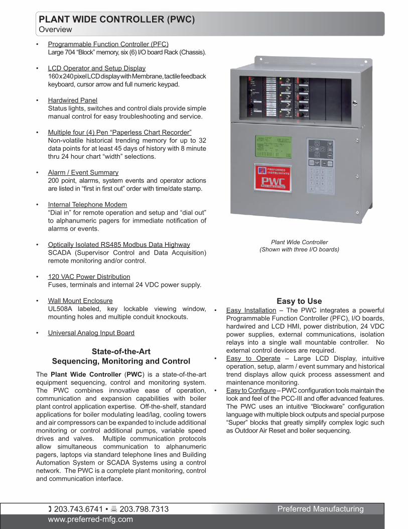
Plant Wide ControllerBoiler Modulating Lead/Lag, Deaerator and Surge Tank Control Example Application
Boiler Modulating Lead/Lag Applications• Full Boiler Modulation - Multiple boiler firing rates are
automatically adjusted to satisfy the overall plant hot water or steam demand. Either unison (parallel) or series modulation is used.
• Improved Steam or Hot Water System Availability Automatic Sequencing ensures that the number of boilers in service meets hot water or steam demand. Tripped equipment is automatically replaced with a standby unit.
• Boiler Monitoring - Flue gas temperature, smoke opacity and boiler draft may be monitored and trended. Warning alarms and burner safety shutdown interlocks may be included.
• Unmanned Boiler Plants - Provides for off-site monitoring and control using internal modem or RS485 interface. Serves as a single plant monitoring point for Building Automation Systems and personal alphanumeric pagers.
Extensive Plant Wide Control Applications• Cooling Tower Optimization – Multiple Tower Cells are
sequenced and fan speed controlled with wet bulb optimization. Substantial fan and chiller electrical savings can be realized.
• Improved E-Gen Fuel System Availability – Fuel pump standby sequencing, day tank level control and fuel storage tank level and leak monitoring.
• Improved Steam System Availability – Condensate transfer and feed pump standby sequencing, Deaerator and Surge tank level monitoring, alarm and remote communications.
• Coordinated Hot Water System Operation – Pumps, isolation valves, distribution pumps and temperature monitoring for reduced thermal stress and energy consumption.
• Fresh Air Dampers, Air Compressors and Fans Sequencing, monitoring, and control are based on the number of boilers online. A single damper failure will not prevent a boiler from firing.
203.743.6741 • 203.798.7313www.preferred-mfg.com
Preferred Manufacturing
PLANT WIDE CONTROLLER (PWC)Configuration
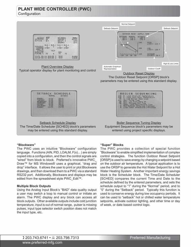
“Blockware”The PWC uses an intuitive “Blockware” configuration language. Functions (AIN, PID, LOALM, F(x)... ) are simply copied into a configuration, and then the control signals are “wired” from block to block. Preferred’s innovative PWC_Draw™ for MS Windows® uses a graphical, “drag and drop” interface. It allows the user to print or plot Blockware drawings, and then download them to a PWC via a standard RS232 port. Additionally, Blockware and displays may be edited from the spreadsheet style PWC_Edit™.
Multiple Block OutputsUsing the Analog Input Block’s “BAD” data quality output a user may switch a loop to manual control or initiate an alarm. The PWC display and any block can access all block outputs. Other available outputs include cold junction temperature, input is out of normal range, pulser is missing pulses, input type selector switch position does not match the input type, etc.
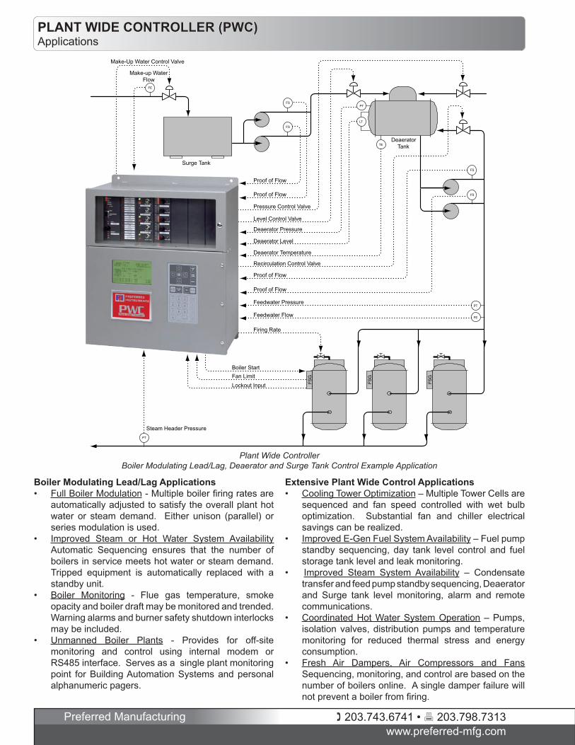
Normal Setpoint
Setback Setpoint
Automatic Graphical Representation Outdoor Cutoff
Setback Setpoint
High & Low Limits
Plant Overview DisplayTypical operator display for plant monitoring and control
Outdoor Reset DisplayThe Outdoor Reset Setpoint [ORSP] block's
parameters may be entered using this standard display.
Setback Schedule DisplayThe Time/Date Scheduler [SCHED] block's parameters
may be entered using this standard display.
Boiler Sequence Tuning DisplayEquipment Sequence block's parameters may be
entered using project specific displays.
“Super” BlocksThe PWC provides a collection of special function “Blockware” to enable simplified implementation of complex control strategies. The function Outdoor Reset Setpoint [ORSP] is used to save energy by changing a setpoint based on the outdoor air temperature. A typical application is to use the ORSP to generate the Hot Water Setpoint for a Hot Water Heating System. Another important energy savings block is the Scheduler block. The Time/Date Scheduler [SCHED] compares the current Time and Date to the schedule defined by the entered parameters, and sets the schedule output to “1” during the “Normal” period, and to “0” during the “Setback” period. Typically this function is used to conserve energy during low occupancy periods. It can be used to “setback” hot or chilled water temperature setpoints, activate outdoor lighting, and other time or day of week, or date based control logic.
203.743.6741 • 203.798.7313www.preferred-mfg.com
Preferred Manufacturing
PLANT WIDE CONTROLLER (PWC)Configuration
LCD Display CommissioningPlant Wide Controller configurations are designed to allow commissioning to be accomplished from the controller mounted displays. Project specific tuning displays may be created to present and group key “Blockware” parameters for field tuning. Additionally, any block parameter may be edited from the front panel display using the “Parameter Edit” mode. Laptop computers are only required when it is necessary to change wiring between blocks or add additional blocks.
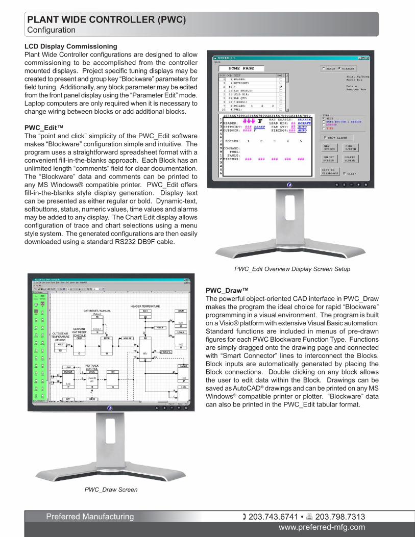
PWC_Edit™The “point and click” simplicity of the PWC_Edit software makes “Blockware” configuration simple and intuitive. The program uses a straightforward spreadsheet format with a convenient fill-in-the-blanks approach. Each Block has an unlimited length “comments” field for clear documentation. The “Blockware” data and comments can be printed to any MS Windows® compatible printer. PWC_Edit offers fill-in-the-blanks style display generation. Display text can be presented as either regular or bold. Dynamic-text, softbuttons, status, numeric values, time values and alarms may be added to any display. The Chart Edit display allows configuration of trace and chart selections using a menu style system. The generated configurations are then easily downloaded using a standard RS232 DB9F cable.
PWC_Edit Overview Display Screen Setup
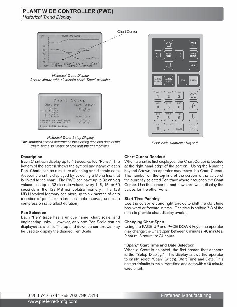
PWC_Draw Screen
PWC_Draw™The powerful object-oriented CAD interface in PWC_Draw makes the program the ideal choice for rapid “Blockware” programming in a visual environment. The program is built on a Visio® platform with extensive Visual Basic automation. Standard functions are included in menus of pre-drawn figures for each PWC Blockware Function Type. Functions are simply dragged onto the drawing page and connected with “Smart Connector” lines to interconnect the Blocks. Block inputs are automatically generated by placing the Block connections. Double clicking on any block allows the user to edit data within the Block. Drawings can be saved as AutoCAD® drawings and can be printed on any MS Windows® compatible printer or plotter. “Blockware” data can also be printed in the PWC_Edit tabular format.
203.743.6741 • 203.798.7313www.preferred-mfg.com
Preferred Manufacturing
PLANT WIDE CONTROLLER (PWC)Historical Trend Display
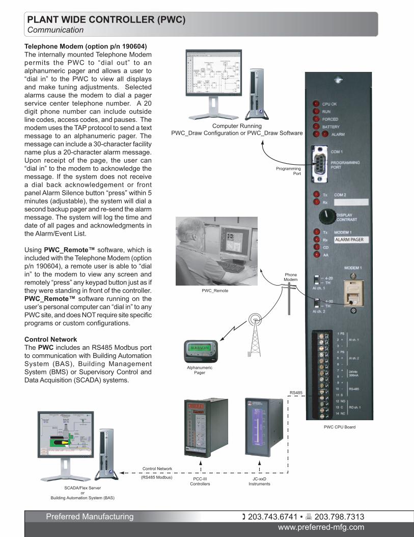
DescriptionEach Chart can display up to 4 traces, called “Pens.” The bottom of the screen shows the symbol and name of each Pen. Charts can be a mixture of analog and discrete data. A specific chart is displayed by selecting a Menu line that is linked to the chart. The PWC can save up to 32 analog values plus up to 32 discrete values every 1, 5, 15, or 60 seconds in the 128 MB non-volatile memory. The 128 MB Historical Memory can store up to six months of data (number of points monitored, sample interval, and data compression ratio affect duration).
Pen Selection Each "Pen" trace has a unique name, chart scale, and engineering units. However, only one Pen Scale can be displayed at a time. The up and down cursor arrows may be used to display the desired Pen Scale.
Chart Cursor ReadoutWhen a chart is first displayed, the Chart Cursor is located at the right hand edge of the screen. Using the Numeric keypad Arrows the operator may move the Chart Cursor. The number on the top line of the screen is the value of the currently selected Pen trace where it touches the Chart Cursor. Use the cursor up and down arrows to display the values for the other Pens.
Start Time PanningUse the cursor left and right arrows to shift the start time backward or forward in time. The time is shifted 7/8 of the span to provide chart display overlap.
Changing Chart SpanUsing the PAGE UP and PAGE DOWN keys, the operator may change the Chart Span between 8 minutes, 40 minutes, 2 hours, 8 hours, or 24 hours.
“Span,” Start Time and Date Selection When a Chart is selected, the first screen that appears is the “Setup Display.” This display allows the operator to easily select “Span” (width), Start Time and Date. This screen defaults to the current time and date with a 40 minute wide chart.
Plant Wide Controller Keypad
Chart Cursor
Historical Trend DisplayScreen shown with 40 minute chart “Span” selection
Historical Trend Setup DisplayThis standard screen determines the starting time and date of the
chart, and also “span” of time that the chart covers.
203.743.6741 • 203.798.7313www.preferred-mfg.com
Preferred Manufacturing
PLANT WIDE CONTROLLER (PWC)Communication
(RS485 Modbus) PCC-IIIControllers
JC-xxDInstruments
Control Network
SCADA/Flex Serveror
Building Automation System (BAS)
PWC_Remote
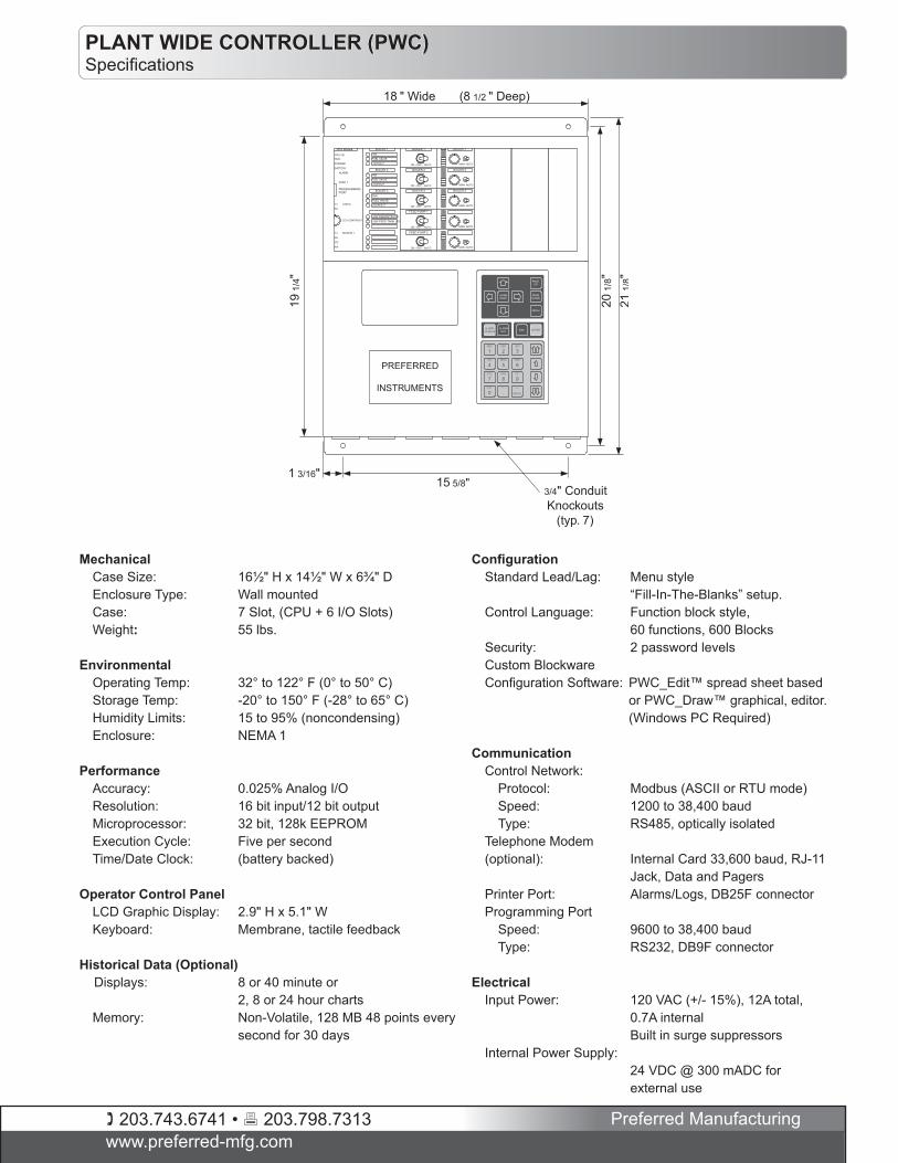
PWC CPU Board
Computer RunningPWC_Draw Configuration or PWC_Draw Software
AlphanumericPager
ProgrammingPort
PhoneModem
RS485
�����������
Telephone Modem (option p/n 190604)The internally mounted Telephone Modem permits the PWC to “dial out” to an alphanumeric pager and allows a user to “dial in” to the PWC to view all displays and make tuning adjustments. Selected alarms cause the modem to dial a pager service center telephone number. A 20 digit phone number can include outside line codes, access codes, and pauses. The modem uses the TAP protocol to send a text message to an alphanumeric pager. The message can include a 30-character facility name plus a 20-character alarm message. Upon receipt of the page, the user can “dial in” to the modem to acknowledge the message. If the system does not receive a dial back acknowledgement or front panel Alarm Silence button “press” within 5 minutes (adjustable), the system will dial a second backup pager and re-send the alarm message. The system will log the time and date of all pages and acknowledgments in the Alarm/Event List.
Using PWC_Remote™ software, which is included with the Telephone Modem (option p/n 190604), a remote user is able to “dial in” to the modem to view any screen and remotely “press” any keypad button just as if they were standing in front of the controller. PWC_Remote™ software running on the user’s personal computer can “dial in” to any PWC site, and does NOT require site specific programs or custom configurations.
Control NetworkThe PWC includes an RS485 Modbus port to communication with Building Automation System (BAS), Building Management System (BMS) or Supervisory Control and Data Acquisition (SCADA) systems.
203.743.6741 • 203.798.7313www.preferred-mfg.com
Preferred Manufacturing
PLANT WIDE CONTROLLER (PWC)Specifications
Mechanical Case Size: 16½" H x 14½" W x 6¾" D Enclosure Type: Wall mounted Case: 7 Slot, (CPU + 6 I/O Slots) Weight: 55 lbs.
Environmental Operating Temp: 32° to 122° F (0° to 50° C) Storage Temp: -20° to 150° F (-28° to 65° C) Humidity Limits: 15 to 95% (noncondensing) Enclosure: NEMA 1
Performance Accuracy: 0.025% Analog I/O Resolution: 16 bit input/12 bit output Microprocessor: 32 bit, 128k EEPROM Execution Cycle: Five per second Time/Date Clock: (battery backed)
Operator Control Panel LCD Graphic Display: 2.9" H x 5.1" W Keyboard: Membrane, tactile feedback
Historical Data (Optional) Displays: 8 or 40 minute or 2, 8 or 24 hour charts Memory: Non-Volatile, 128 MB 48 points every second for 30 days
Configuration Standard Lead/Lag: Menu style “Fill-In-The-Blanks” setup. Control Language: Function block style, 60 functions, 600 Blocks Security: 2 password levels Custom Blockware Configuration Software: PWC_Edit™ spread sheet based
or PWC_Draw™ graphical, editor. (Windows PC Required)
Communication Control Network: Protocol: Modbus (ASCII or RTU mode) Speed: 1200 to 38,400 baud Type: RS485, optically isolated Telephone Modem (optional): Internal Card 33,600 baud, RJ-11 Jack, Data and Pagers Printer Port: Alarms/Logs, DB25F connector Programming Port Speed: 9600 to 38,400 baud Type: RS232, DB9F connector
Electrical Input Power: 120 VAC (+/- 15%), 12A total, 0.7A internal Built in surge suppressors Internal Power Supply: 24 VDC @ 300 mADC for external use
G
G
G
G
G
15 5/8"1 3/16"
18 " Wide (8 1/2 " Deep)
19 1
/4"
20 1
/8"
21 1
/8"
3/4" ConduitKnockouts
(typ. 7)
FAN
FUEL VALVE
LOCKOUT
BOILER 1
FAN
FUEL VALVE
LOCKOUT
BOILER 2
FANFUEL VALVELOCKOUT
BOILER 3
LOW FEEDWTR PSILOW FEED TANK LEV
MAN AUTO
BOILER 1
MAN AUTO
BOILER 2
MAN AUTO
BOILER 3
MAN AUTO
MAN AUTO
RUNCPU OK
FORCED
CPU Module
ALARM
BATTERY
COM 1
PROGRAMMINGPORT
Tx MODEM 1
Rx
CD
AA
Tx COM 2
Rx
LCD CONTRAST
BOILER 2
ON - OFF - AUTO
BOILER 1
BOILER 3
ON - OFF - AUTO
FEED PUMP 1
ON - OFF - AUTO
FEED PUMP 2
ON - OFF - AUTO
ON - OFF - AUTO
PREFERRED
INSTRUMENTS
ABC
1DEF
2GHI
3JKL
4MNO
5STU
7VWX
8YZ "
9% # ,
0: < >
./ + -
SPACE
PQR
6
PAGEDOWN
PAGEUP
MENU
HOMEPAGE
ESC ENTERALARMLIST
ALARMSILENCE
203.743.6741 • 203.798.7313www.preferred-mfg.com
Preferred Manufacturing
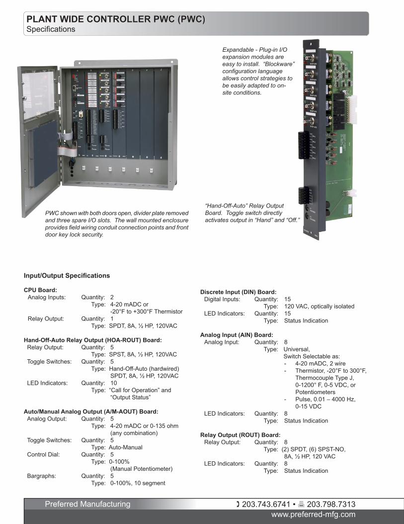
PLANT WIDE CONTROLLER PWC (PWC)Specifications
Expandable - Plug-in I/O expansion modules are easy to install. “Blockware” configuration language allows control strategies to be easily adapted to on-site conditions.
Input/Output Specifications
CPU Board: Analog Inputs: Quantity: 2 Type: 4-20 mADC or -20°F to +300°F Thermistor Relay Output: Quantity: 1 Type: SPDT, 8A, ½ HP, 120VAC
Hand-Off-Auto Relay Output (HOA-ROUT) Board: Relay Output: Quantity: 5 Type: SPST, 8A, ½ HP, 120VAC Toggle Switches: Quantity: 5 Type: Hand-Off-Auto (hardwired) SPDT, 8A, ½ HP, 120VAC LED Indicators: Quantity: 10 Type: “Call for Operation” and “Output Status”
Auto/Manual Analog Output (A/M-AOUT) Board: Analog Output: Quantity: 5 Type: 4-20 mADC or 0-135 ohm (any combination) Toggle Switches: Quantity: 5 Type: Auto-Manual Control Dial: Quantity: 5 Type: 0-100% (Manual Potentiometer) Bargraphs: Quantity: 5 Type: 0-100%, 10 segment
Discrete Input (DIN) Board: Digital Inputs: Quantity: 15 Type: 120 VAC, optically isolated LED Indicators: Quantity: 15 Type: Status Indication
Analog Input (AIN) Board: Analog Input: Quantity: 8 Type: Universal,
Switch Selectable as: - 4-20 mADC, 2 wire - Thermistor, -20°F to 300°F,
Thermocouple Type J, 0-1200° F, 0-5 VDC, or Potentiometers
- Pulse, 0.01 – 4000 Hz, 0-15 VDC LED Indicators: Quantity: 8 Type: Status Indication
Relay Output (ROUT) Board: Relay Output: Quantity: 8 Type: (2) SPDT, (6) SPST-NO, 8A, ½ HP, 120 VAC LED Indicators: Quantity: 8 Type: Status Indication
PWC shown with both doors open, divider plate removed and three spare I/O slots. The wall mounted enclosure provides field wiring conduit connection points and front door key lock security.
“Hand-Off-Auto” Relay Output Board. Toggle switch directly activates output in “Hand” and “Off.”
203.743.6741 • 203.798.7313www.preferred-mfg.com
Preferred Manufacturing
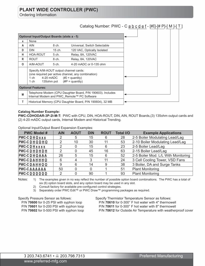
Optional Input/Output Boards (slots a - f):x NoneA AIN 8 ch. Universal, Switch SelectableD DIN 15 ch. 120 VAC, Optically IsolatedH HOA-ROUT 5 ch. Relay, 8A, 120VACR ROUT 8 ch. Relay, 8A, 120VAC
O A/M-AOUT 5 ch. 4-20 mADC or 0-135 ohm
Specify A/M-AOUT output channel cards: (one required per active channel, any combination)1 ch 4-20 mADC (#I = quantity)1 ch 135ohm pot (#P = quantity)
Optional Features:
M Telephone Modem (CPU Daughter Board, P/N 190603). Includes Internal Modem and PWC_Remote™ PC Software
T Historical Memory (CPU Daughter Board, P/N 190604), 32 MB
Catalog Number: PWC - C a b c d e f - [#I]-[# P]-[ M ]-[ T ]
PWC Model # AIN AOUT DIN ROUT Total I/O Example ApplicationsPWC-C D H O x x x 2 5 15 6 28 2-5 Boiler Modulating Lead/LagPWC-C D H O D H O 2 10 30 11 53 2-10 Boiler Modulating Lead/LagPWC-C D H x x x x 2 0 15 6 23 2-5 Boiler Lead/LagPWC-C D H D H D H 2 0 45 16 63 2-15 Boiler Lead/LagPWC-C D H O A A A 26 5 15 6 52 2-5 Boiler Mod. L/L With MonitoringPWC-C D A H H H O 6 4 3 11 24 3 Cell Cooling Tower, VSD FansPWC-C D A H H O O 9 6 14 9 38 3 Boiler, DA and Surge TanksPWC-C A A A A A A 50 0 0 1 51 Plant MonitoringPWC-C D D D D D D 2 0 90 1 93 Plant Monitoring
Catalog Number Example:PWC-CDHODAR-3P-2I-M-T: PWC with CPU, DIN, HOA-ROUT, DIN, AIN, ROUT Boards,(3) 135ohm output cards and (2) 4-20 mADC output cards, Internal Modem and Historical Trending.
Optional Input/Output Board Expansion Examples:
Notes: 1) The examples given in no way reflect the number of possible option board combinations. The PWC has a total of six (6) option board slots, and any option board may be used in any slot.
2) Consult factory for available pre-configured control strategies. 3) Separately order PWC Edit™ or PWC Draw™ programming packages as required.
Specify Pressure Sensor as follows: P/N 70600 for 0-25 PSI with syphon loop P/N 70601 for 0-200 PSI with syphon loop P/N 70602 for 0-500 PSI with syphon loop
Specify Thermistor Temperature Sensor as follows: P/N 70610 for 0-300° F hot water with 4" thermowell P/N 70611 for 0-300° F hot water with 8" thermowell P/N 70612 for Outside Air Temperature with weatherproof cover
PLANT WIDE CONTROLLER (PWC)Ordering Information
203.743.6741 • 203.798.7313www.preferred-mfg.com
Preferred Manufacturing
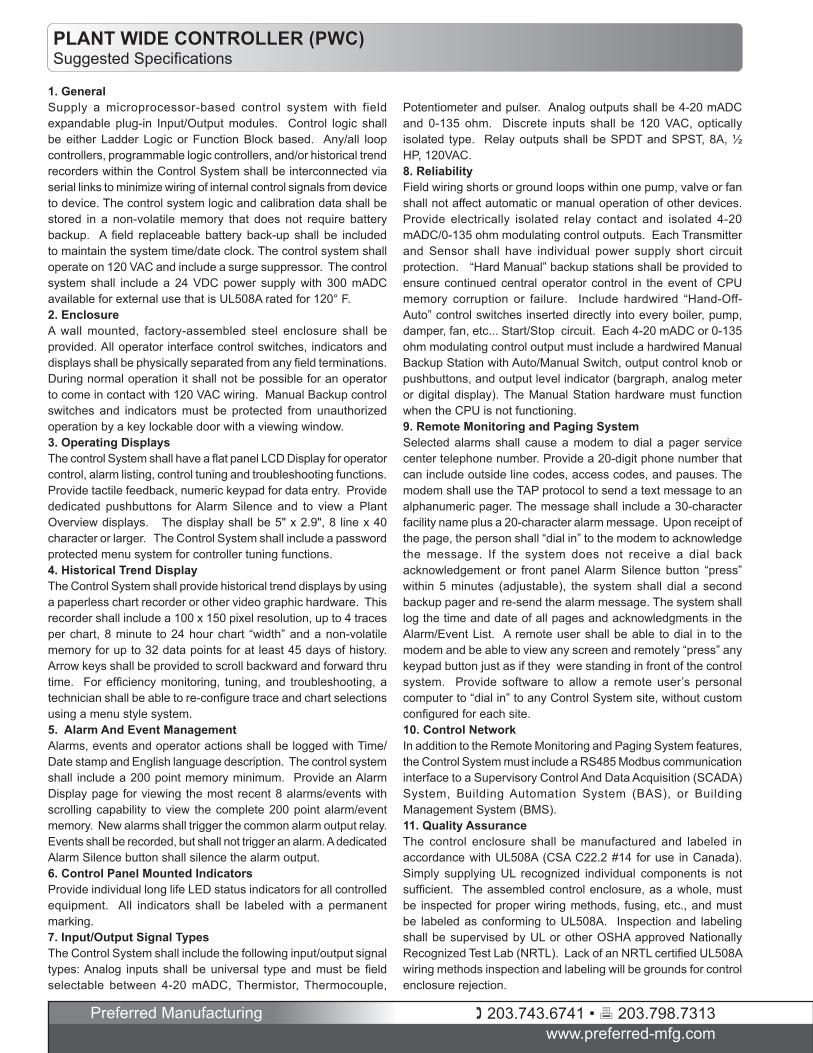
PLANT WIDE CONTROLLER (PWC)Suggested Specifications
1. GeneralSupply a microprocessor-based control system with field expandable plug-in Input/Output modules. Control logic shall be either Ladder Logic or Function Block based. Any/all loop controllers, programmable logic controllers, and/or historical trend recorders within the Control System shall be interconnected via serial links to minimize wiring of internal control signals from device to device. The control system logic and calibration data shall be stored in a non-volatile memory that does not require battery backup. A field replaceable battery back-up shall be included to maintain the system time/date clock. The control system shall operate on 120 VAC and include a surge suppressor. The control system shall include a 24 VDC power supply with 300 mADC available for external use that is UL508A rated for 120° F. 2. EnclosureA wall mounted, factory-assembled steel enclosure shall be provided. All operator interface control switches, indicators and displays shall be physically separated from any field terminations. During normal operation it shall not be possible for an operator to come in contact with 120 VAC wiring. Manual Backup control switches and indicators must be protected from unauthorized operation by a key lockable door with a viewing window.3. Operating DisplaysThe control System shall have a flat panel LCD Display for operator control, alarm listing, control tuning and troubleshooting functions. Provide tactile feedback, numeric keypad for data entry. Provide dedicated pushbuttons for Alarm Silence and to view a Plant Overview displays. The display shall be 5" x 2.9", 8 line x 40 character or larger. The Control System shall include a password protected menu system for controller tuning functions.4. Historical Trend DisplayThe Control System shall provide historical trend displays by using a paperless chart recorder or other video graphic hardware. This recorder shall include a 100 x 150 pixel resolution, up to 4 traces per chart, 8 minute to 24 hour chart “width” and a non-volatile memory for up to 32 data points for at least 45 days of history. Arrow keys shall be provided to scroll backward and forward thru time. For efficiency monitoring, tuning, and troubleshooting, a technician shall be able to re-configure trace and chart selections using a menu style system. 5. Alarm And Event ManagementAlarms, events and operator actions shall be logged with Time/Date stamp and English language description. The control system shall include a 200 point memory minimum. Provide an Alarm Display page for viewing the most recent 8 alarms/events with scrolling capability to view the complete 200 point alarm/event memory. New alarms shall trigger the common alarm output relay. Events shall be recorded, but shall not trigger an alarm. A dedicated Alarm Silence button shall silence the alarm output.6. Control Panel Mounted IndicatorsProvide individual long life LED status indicators for all controlled equipment. All indicators shall be labeled with a permanent marking. 7. Input/Output Signal TypesThe Control System shall include the following input/output signal types: Analog inputs shall be universal type and must be field selectable between 4-20 mADC, Thermistor, Thermocouple,
Potentiometer and pulser. Analog outputs shall be 4-20 mADC and 0-135 ohm. Discrete inputs shall be 120 VAC, optically isolated type. Relay outputs shall be SPDT and SPST, 8A, ½ HP, 120VAC.8. ReliabilityField wiring shorts or ground loops within one pump, valve or fan shall not affect automatic or manual operation of other devices. Provide electrically isolated relay contact and isolated 4-20 mADC/0-135 ohm modulating control outputs. Each Transmitter and Sensor shall have individual power supply short circuit protection. “Hard Manual” backup stations shall be provided to ensure continued central operator control in the event of CPU memory corruption or failure. Include hardwired “Hand-Off-Auto” control switches inserted directly into every boiler, pump, damper, fan, etc... Start/Stop circuit. Each 4-20 mADC or 0-135 ohm modulating control output must include a hardwired Manual Backup Station with Auto/Manual Switch, output control knob or pushbuttons, and output level indicator (bargraph, analog meter or digital display). The Manual Station hardware must function when the CPU is not functioning.9. Remote Monitoring and Paging SystemSelected alarms shall cause a modem to dial a pager service center telephone number. Provide a 20-digit phone number that can include outside line codes, access codes, and pauses. The modem shall use the TAP protocol to send a text message to an alphanumeric pager. The message shall include a 30-character facility name plus a 20-character alarm message. Upon receipt of the page, the person shall “dial in” to the modem to acknowledge the message. If the system does not receive a dial back acknowledgement or front panel Alarm Silence button “press” within 5 minutes (adjustable), the system shall dial a second backup pager and re-send the alarm message. The system shall log the time and date of all pages and acknowledgments in the Alarm/Event List. A remote user shall be able to dial in to the modem and be able to view any screen and remotely “press” any keypad button just as if they were standing in front of the control system. Provide software to allow a remote user’s personal computer to “dial in” to any Control System site, without custom configured for each site.10. Control NetworkIn addition to the Remote Monitoring and Paging System features, the Control System must include a RS485 Modbus communication interface to a Supervisory Control And Data Acquisition (SCADA) System, Building Automation System (BAS), or Building Management System (BMS). 11. Quality AssuranceThe control enclosure shall be manufactured and labeled in accordance with UL508A (CSA C22.2 #14 for use in Canada). Simply supplying UL recognized individual components is not sufficient. The assembled control enclosure, as a whole, must be inspected for proper wiring methods, fusing, etc., and must be labeled as conforming to UL508A. Inspection and labeling shall be supervised by UL or other OSHA approved Nationally Recognized Test Lab (NRTL). Lack of an NRTL certified UL508A wiring methods inspection and labeling will be grounds for control enclosure rejection.