Embed Size (px)
Citation preview
1
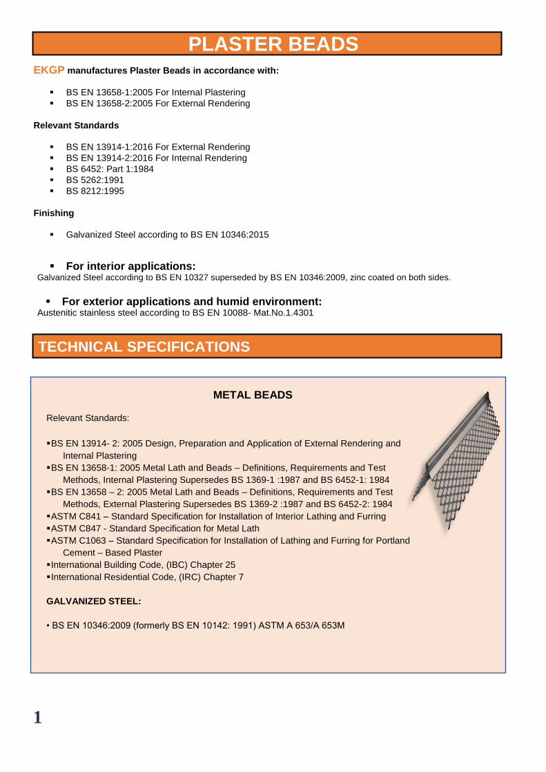
PLASTER BEADS
EKGP manufactures Plaster Beads in accordance with:
▪ BS EN 13658-1:2005 For Internal Plastering ▪ BS EN 13658-2:2005 For External Rendering
Relevant Standards
▪ BS EN 13914-1:2016 For External Rendering ▪ BS EN 13914-2:2016 For Internal Rendering ▪ BS 6452: Part 1:1984 ▪ BS 5262:1991 ▪ BS 8212:1995
Finishing
▪ Galvanized Steel according to BS EN 10346:2015
▪ For interior applications: Galvanized Steel according to BS EN 10327 superseded by BS EN 10346:2009, zinc coated on both sides.
▪ For exterior applications and humid environment:
Austenitic stainless steel according to BS EN 10088- Mat.No.1.4301
TECHNICAL SPECIFICATIONS
METAL BEADS
Relevant Standards:
▪ BS EN 13914- 2: 2005 Design, Preparation and Application of External Rendering and
Internal Plastering
▪ BS EN 13658-1: 2005 Metal Lath and Beads – Definitions, Requirements and Test
Methods, Internal Plastering Supersedes BS 1369-1 :1987 and BS 6452-1: 1984
▪ BS EN 13658 – 2: 2005 Metal Lath and Beads – Definitions, Requirements and Test
Methods, External Plastering Supersedes BS 1369-2 :1987 and BS 6452-2: 1984
▪ ASTM C841 – Standard Specification for Installation of Interior Lathing and Furring
▪ ASTM C847 - Standard Specification for Metal Lath
▪ ASTM C1063 – Standard Specification for Installation of Lathing and Furring for Portland
Cement – Based Plaster
▪ International Building Code, (IBC) Chapter 25
▪ International Residential Code, (IRC) Chapter 7
GALVANIZED STEEL:
• BS EN 10346:2009 (formerly BS EN 10142: 1991) ASTM A 653/A 653M
2
ANGLE BEAD
CORNER MESH
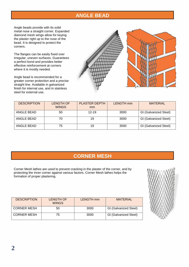
Angle beads provide with its solid
metal nose a straight corner. Expanded
diamond mesh wings allow for keying
the plaster right up to the nose of the
bead. It is designed to protect the
corners.
The flanges can be easily fixed over
irregular, uneven surfaces. Guarantees
a perfect bond and provides better
effective reinforcement at corners
where it is mostly needed.
Angle bead is recommended for a
greater corner protection and a precise
straight line. Available in galvanized
finish for internal use, and in stainless
steel for external use.
DESCRIPTION LENGTH OF WINGS
PLASTER DEPTH mm
LENGTH mm MATERIAL
ANGLE BEAD 50 12-19 3000 GI (Galvanized Steel)
ANGLE BEAD 70 19 3000 GI (Galvanized Steel)
ANGLE BEAD 75 19 3000 GI (Galvanized Steel)
DESCRIPTION LENGTH OF WINGS
LENGTH mm MATERIAL
CORNER MESH 50 3000 GI (Galvanized Steel)
CORNER MESH 75 3000 GI (Galvanized Steel)
Corner Mesh lathes are used to prevent cracking in the plaster of the corner, and by protecting the inner corner against various factors. Corner Mesh lathes helps the formation of proper plastering.
3
CONTROL JOINT BEAD
ARCHITRAVE BEAD
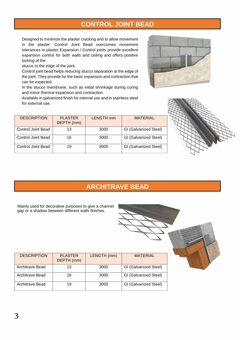
Mainly used for decorative purposes to give a channel gap or a shadow between different walls finishes.
DESCRIPTION PLASTER DEPTH (mm)
LENGTH mm MATERIAL
Control Joint Bead 13 3000 GI (Galvanized Steel)
Control Joint Bead 16 3000 GI (Galvanized Steel)
Control Joint Bead 19 3000 GI (Galvanized Steel)
DESCRIPTION PLASTER DEPTH (mm)
LENGTH (mm) MATERIAL
Architrave Bead 13 3000 GI (Galvanized Steel)
Architrave Bead 16 3000 GI (Galvanized Steel)
Architrave Bead 19 3000 GI (Galvanized Steel)
Designed to minimize the plaster cracking and to allow movement
in the plaster. Control Joint Bead overcomes movement
tolerances in plaster Expansion / Control joints provide excellent
expansion control for both walls and ceiling and offers positive
locking of the
stucco to the edge of the joint.
Control joint bead helps reducing stucco separation at the edge of
the joint. They provide for the basic expansion and contraction that
can be expected
in the stucco membrane, such as initial shrinkage during curing
and minor thermal expansion and contraction.
Available in galvanized finish for internal use and in stainless steel
for external use.
4
PLASTER STOP BEAD
COIL LATH
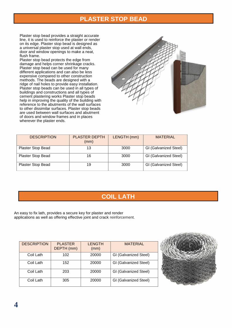
An easy to fix lath, provides a secure key for plaster and render applications as well as offering effective joint and crack reinforcement.
DESCRIPTION PLASTER DEPTH (mm)
LENGTH (mm) MATERIAL
Plaster Stop Bead 13 3000 GI (Galvanized Steel)
Plaster Stop Bead 16 3000 GI (Galvanized Steel)
Plaster Stop Bead 19 3000 GI (Galvanized Steel)
DESCRIPTION PLASTER DEPTH (mm)
LENGTH (mm)
MATERIAL
Coil Lath 102 20000 GI (Galvanized Steel)
Coil Lath 152 20000 GI (Galvanized Steel)
Coil Lath 203 20000 GI (Galvanized Steel)
Coil Lath 305 20000 GI (Galvanized Steel)
Plaster stop bead provides a straight accurate line, it is used to reinforce the plaster or render on its edge. Plaster stop bead is designed as a universal plaster stop used at wall ends, door and window openings to make a neat, flush frame. Plaster stop bead protects the edge from damage and helps corner shrinkage cracks. Plaster stop bead can be used for many different applications and can also be less expensive compared to other construction methods. The beads are designed with a ridge of nail holes to provide easy installation. Plaster stop beads can be used in all types of buildings and constructions and all types of cement plastering works Plaster stop beads help in improving the quality of the building with reference to the abutments of the wall surfaces to other dissimilar surfaces. Plaster stop beads are used between wall surfaces and abutment of doors and window frames and in places wherever the plaster ends.
5
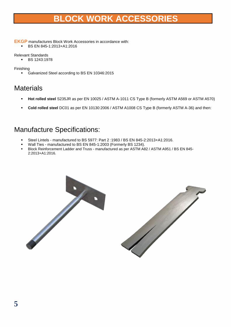
BLOCK WORK ACCESSORIES
EKGP manufactures Block Work Accessories in accordance with:
▪ BS EN 845-1:2013+A1:2016
Relevant Standards ▪ BS 1243:1978
Finishing
▪ Galvanized Steel according to BS EN 10346:2015
Materials
▪ Hot rolled steel S235JR as per EN 10025 / ASTM A-1011 CS Type B (formerly ASTM A569 or ASTM A570)
▪ Cold rolled steel DC01 as per EN 10130:2006 / ASTM A1008 CS Type B (formerly ASTM A-36) and then:
Manufacture Specifications:
▪ Steel Lintels - manufactured to BS 5977: Part 2 :1983 / BS EN 845-2:2013+A1:2016. ▪ Wall Ties - manufactured to BS EN 845-1:2003 (Formerly BS 1234). ▪ Block Reinforcement Ladder and Truss - manufactured as per ASTM A82 / ASTM A951 / BS EN 845-
2:2013+A1:2016.
6
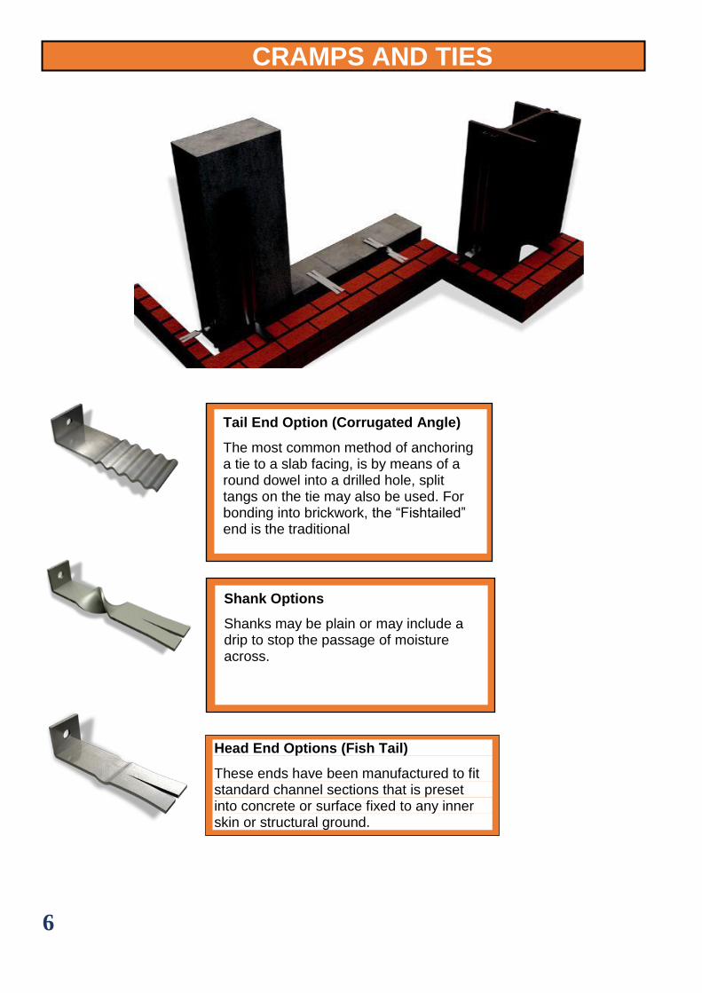
CRAMPS AND TIES
Head End Options (Fish Tail)
These ends have been manufactured to fit standard channel sections that is preset into concrete or surface fixed to any inner skin or structural ground.
Tail End Option (Corrugated Angle)
The most common method of anchoring a tie to a slab facing, is by means of a round dowel into a drilled hole, split tangs on the tie may also be used. For bonding into brickwork, the “Fishtailed” end is the traditional
Shank Options
Shanks may be plain or may include a drip to stop the passage of moisture across.
7
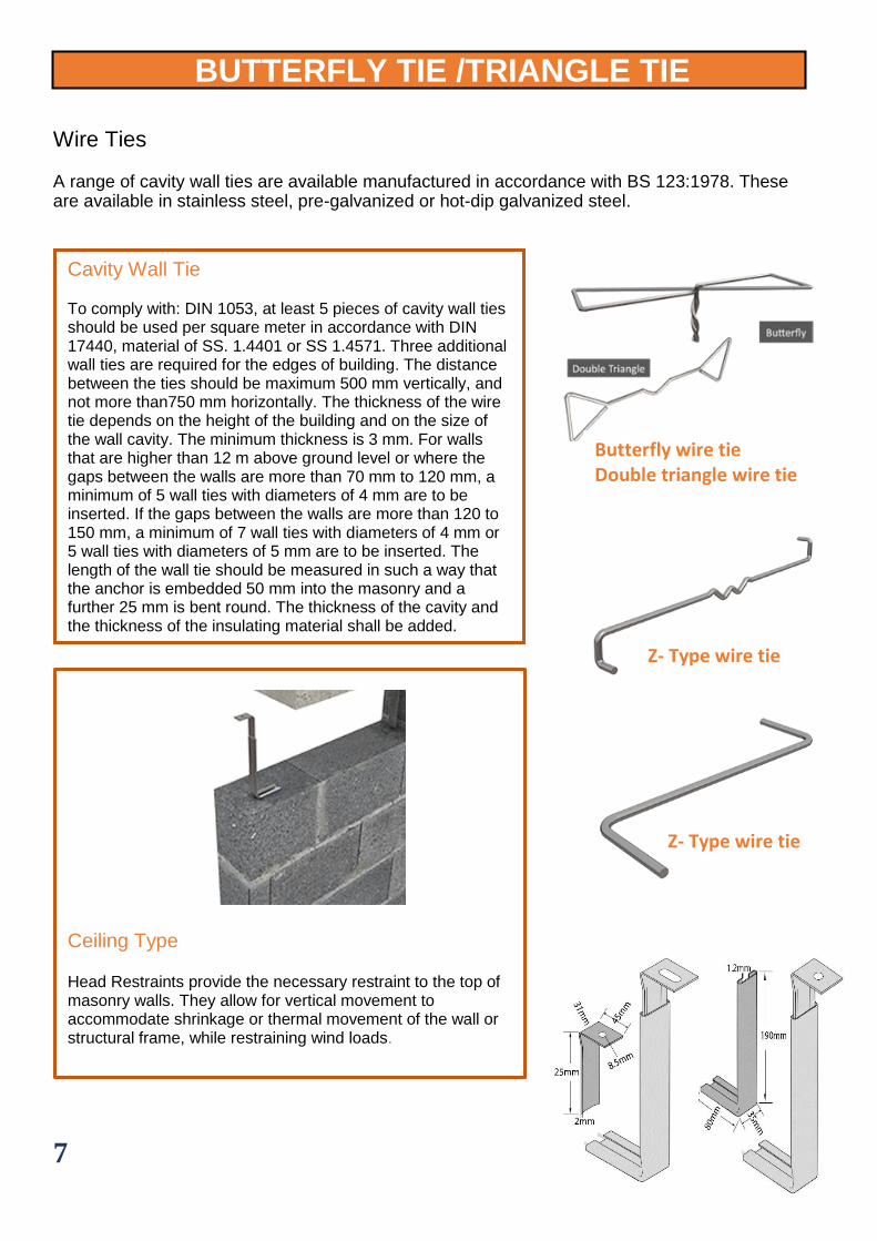
Ceiling Type Head Restraints provide the necessary restraint to the top of masonry walls. They allow for vertical movement to accommodate shrinkage or thermal movement of the wall or structural frame, while restraining wind loads.
BUTTERFLY TIE /TRIANGLE TIE Wire Ties
A range of cavity wall ties are available manufactured in accordance with BS 123:1978. These are available in stainless steel, pre-galvanized or hot-dip galvanized steel.
Butterfly wire tie Double triangle wire tie
Z- Type wire tie
Z- Type wire tie
Cavity Wall Tie To comply with: DIN 1053, at least 5 pieces of cavity wall ties should be used per square meter in accordance with DIN 17440, material of SS. 1.4401 or SS 1.4571. Three additional wall ties are required for the edges of building. The distance between the ties should be maximum 500 mm vertically, and not more than750 mm horizontally. The thickness of the wire tie depends on the height of the building and on the size of the wall cavity. The minimum thickness is 3 mm. For walls that are higher than 12 m above ground level or where the gaps between the walls are more than 70 mm to 120 mm, a minimum of 5 wall ties with diameters of 4 mm are to be inserted. If the gaps between the walls are more than 120 to 150 mm, a minimum of 7 wall ties with diameters of 4 mm or 5 wall ties with diameters of 5 mm are to be inserted. The length of the wall tie should be measured in such a way that the anchor is embedded 50 mm into the masonry and a further 25 mm is bent round. The thickness of the cavity and the thickness of the insulating material shall be added.
8
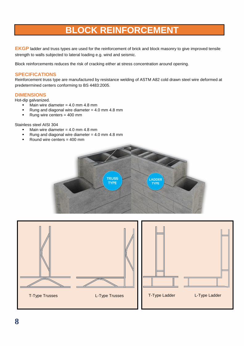
BLOCK REINFORCEMENT
EKGP ladder and truss types are used for the reinforcement of brick and block masonry to give improved tensile
strength to walls subjected to lateral loading e.g. wind and seismic. Block reinforcements reduces the risk of cracking either at stress concentration around opening.
SPECIFICATIONS Reinforcement truss type are manufactured by resistance welding of ASTM A82 cold drawn steel wire deformed at
predetermined centers conforming to BS 4483:2005.
DIMENSIONS Hot-dip galvanized.
▪ Main wire diameter = 4.0 mm 4.8 mm ▪ Rung and diagonal wire diameter = 4.0 mm 4.8 mm ▪ Rung wire centers = 400 mm
Stainless steel AISI 304 ▪ Main wire diameter = 4.0 mm 4.8 mm ▪ Rung and diagonal wire diameter = 4.0 mm 4.8 mm ▪ Round wire centers = 400 mm
T-Type Trusses L-Type Trusses T-Type Ladder L-Type Ladder