Embed Size (px)
Citation preview

Engineering Fracture MecMnics, 1971,Vol. 3, pp. 435-451. Pergamon Press. Printed in Great Britain
PLASTIC INTENSITY FACTORS FOR CRACKED PLATESt
PETER D. HILTON and JOHN W. HUTCHINSON Harvard University, Cambridge, Mass. 02138, U.S.A.
Abstract-An elastic-plastic analysis is performed for two problems relevant to fracture mechanics: a semiinfinite body with an edge crack in a far out-of-plane shearing field and an infinite plate under plane stress conditions containing a finite line crack in a remote tensile field. Amplitudes of the dominant singularity in the plastic region at the crack tip, the plastic stress and strain intensity factors, are calculated for applied stress levels approaching the yield stress. A technique is developed for using the dominant singular solution in conjunction with the finite element method to make accurate calculations for the near-tip fields. Additionally, a comparative study of deformation theory with flow theory is performed for cracks in an anti-plane shear field. Elastic fracture mechanics is extended to high levels of applied stress for which the plastic zone is no longer small compared to the crack length by relating the critical stress for fracture initiation to the plastic intensity factors.
INTRODUCTION AN ELASTiC-plastic analysis of plates of hardening material containing cracks will be carried out. This analysis is then employed to extend classical fracture mechanics to the case when the plastic zone about the crack tip can no longer be considered small. Work pertinent to this area of fracture mechanics has been reviewed by McClintock and Irwinj l] and very recently by Rice [2].
Initiation of crack growth depends on the stress and strain fields in the immediate vicinity of the crack tip. For the cases considered in the present study, cracks in remote anti-plane shear and tensile fields, these near-tip solutions are known except for their amplitudes, the plastic stress and strain intensity factors which relate the behavior at the crack tip to the geometry and applied stress. In the small scale yielding range, when the plastic zone about the crack tip is small in comparison with the crack length, the plastic intensity factors can be related directly to the elastic stress intensity factor. Results of this type, which will be further discussed, are due to Hult and McClintock[3], Neuber[4] and Rice[5] for the anti-plane shear case and to Rice and Rosengren[6] and Hutchinson [7, 8] for the tensile case. At higher values of applied stress, in what will be referred to as the large scale yielding range, the plastic zone is no longer small compared to the crack length and the elastic stress intensity factor is no longer relevant without some modification.
Use of plastic intensity factors is in no way restricted by the extent of the plastic zone; and thus the concept of a critical value of the plastic stress or strain intensity factor can be introduced and employed in much the same way as the elastic stress intensity factor is used in classical fracture mechanics. A numerical procedure is developed here which combines details of the dominant singularity in the plastic region with the finite element technique for accurate computation of the plastic intensity factors. Standard numerical techniques which have been applied to these crack problems with no special treatment for the singularity at the crack tip fail to give accurate solutions about the tip, the region of prime interest.
[Presented at the Third National Symposium on Fracture Mechanics, Lehigh University, Bethlehem, Pa., August 25-27, 1969.
435
•

436 P. D. HILTO N and J . W. HU TC H INSON
T he probl em of a semi-infinite bod y with an edge crac k subjected to a far out-ofplane shear field is used to illustra te the techniqu es developed. Accuracy estima tes fo r thi s problem fo r th e case of a deformati on theory of pla sticity are es tablished throu gh co mparisons with the re sults which Rice [5] obtained with a differen t techniqu e. F urth er , th e ca lc ula tions are re peated with an inc reme nta l theo ry to stud y th e discrep ancies be tween the p redictions of deformation theory and those bas ed on flow theory . The major co ntri butio n of thi s wo rk is the result s which have been obta ined fo r a finit e line c rack in an infinit e sheet und er plan e stress co nditions subjec ted to a te nsile field .
PLASTI C STRESS AND STRAIN INTENSITY FAC TORS
T he do minant singu lar term of the elastic so lution in the ne ighborhood of a crack tip is wr itten as
(1)
where ( I'. 0) are polar coordinates ce nte re d at the tip. f A co llection of e las tic so lutio ns to crack problems for a va riety of geo metries an d load ing co nditions is given in the review paper by Paris a nd Sih [9] . Fo r all loa dings and geomet ries suc h th at th e stress fields are symmetric (or ant isyrnrnetric), th e circumferen tial var iat ion of the st ress field, &;;(8), is independen t of additional features of both the geometr y and the bou ndary co nditions of the pa rt icular problem co nsidered . Only the amp litude K ef' co mmon ly ca lled the st ress inte ns ity fac to r, varies fro m problem to pro blem. Fract ure initiat ion takes place , for a given set of co nd itions. when the amplitude of th e st res s field at th e crack tip reaches a critica l va lue . Th is approac h pre sum es that the plastic l o ne is sufficie ntly sma ll so that ( I) rep resents th e stre ss field accura te ly in the ne ighbo rhood of the crack tip outs ide th e plastic l one.
It is no w st andard proced nre to expe rimentally determine the va lue of the stress intensity factor at which fracture initiates an d to apply the result s to initial frac ture predict ion for othe r configurations. T here are a nu mbe r of necessaril y re st ricti ve condition s w hich must be p lace d on this technique , and det ails such as co nditio ns ap proac hing plane stress and p lane strain mus t be different iated as discussed in [10].
A simple example wh ich illustr ate s elas tic frac ture mec hanics is that of an infinite (T u = ~ a'l j {H) (1 )
v 2m"
whe re ( I'. 0) are po lar coordinates ce nte red at th e tip .f A co llect ion of e las tic so lutions to c rack problems for a va riety of geometries and loading co nditions is given in the rev iew paper by Paris and Sih [9]. Fo r all loadings and geomet ries such th at th e stress fields are symme tr ic (or ant isy rnmet ric) , th e circu mfe re ntial variation of th e stress field , lfiJ(8) , is independent of additional feat ures of both the geometry and the boundary co nditio ns of the parti cul ar pro blem co nsidered . On ly the amp litude K ef, co mmon ly ca lled th e stress in tens ity facto r, varies fro m problem to problem. Fractu re initi at ion takes place, fo r a given set of cond ition s . when the amplitude of th e st res s field at the crack tip reaches a critica l va lue. Thi s approac h presum es th a i the plasti c l o ne is sufficie ntly small so that ( I ) represents the st re ss field accu rate ly in the ne ighb orhood of the crack tip outs ide the p lastic l one.
It is no w standard procednre to expe rimentally determine the va lue of the st re ss inte nsity factor at which fracture initi ates and to apply the results to initial fract ure predict ion for ot her configurat ions . There are a numbe r of necessaril y re strictive con ditio ns w hich mu s t be placed on this techniq ue , and details such as co nd itio ns approaching plane stress and plane strain must be different iated as discussed in [10].
A simp le example which illustr ate s elast ic fracture mech an ics is that of an infin ite
437 Plastic intensity factors
As discussed irr the Introduction, the dominant singularity in the plastic zone for hardening materials will be exploited to extend elastic fracture mechanics, and the plastic stress (or strain) intensity factor associated with the dominant term for the neartip fields will be used in a manner analogous to the elastic stress intensity factor to correlate fracture initiation results.
A small strain formulation of plasticity is used as the basis for the present studies. The tensile stress-strain relations
<T~1 (3)
<T>1
are chosen to model the tensile elastic-plastic behavior of the material where the material coefficient is n.
For the present discussion a total deformation theory of plasticity is employed. Plastic deformation is assumed to be independent of the hydrostatic component of stress, <Tkk, and completely determined by the first invariant of the stress deviator Sij = <Tlj -!<TkkOij. This invariant, the 'effective stress' <Te, is defined by <Tl = fSijsij. For simple tension <T = <Tand the Mises yield condition is <T 1.The generalized stresse e strain relationship which reduces to (3) for simple tension is
ejj/(l + v); Sij =
[ee/(l +v)](l-nlln eij/(l +v); <Te > 1
where v is Poisson's ratio, the strain deviator is elj = €ij-1€ppOij and the effective strain ee is defined by ee2 ~BiAj. In the subsequent formulation it will be assumed that no unloading occurs for the monotonic loading histories considered in this paper. This necessitates an a posteriori check of the solution to assure that this assumption has not been violated.
As in the elastic analysis, the dominant singular term of the asymptotic expansion at the crack tip can be written as an intensity factor multiplying a function which is independent of geometry and boundary conditions. For plane stress, plane strain, and anti-plane shear the dominant fields associated with a 'power hardening material' can be written in the followingform
(5)
where K£ (Ka)n and where the dimensionless functions of 0, a-ij and Eij, are detailed for plane stress and plane strain in [8].t
In the region at the crack tip dominated by the singularity solution (5) the deformation is proportional, that is, the relative magnitudes of the stress components do not change with increasing applied load. For this reason, (5) is valid for flow theory as well as deformation theory; however, in general, the amplitudes will differ depending on which theory is employed.
tUnlike in [8], here r is the distance from the crack tip and has not been normalized by the crack length 2a.

438 P. D. HILTON and J. W. HUTCHINSON p{a.si"t' c
It must be emphasized that the concept of a¥ eIa!;tic strain intensity factor associated with a dominant singularity is tied to hardening materials. The distribution of strain at the tip of a crack in a perfectly plastic material is no longer in one to one correspondence with the stress distribution and, in most cases, €iPJ) will depend on the applied stress. Alternate measures of the crack tip deformation are possible in this limiting case, but they will not be dwelt on here.
Asymptotic expressions relating the plastic intensity factors to the elastic stress intensity factor, valid for small scale yielding, can be obtained using the methods outlined in [6, 7]. These results are of the form
(6)
and values of the coefficients en, which depend on the hardening coefficient, are given for a number of cases for both plane stress and plane strain in [8]. For an infinite plate containing a line crack of length 2a, K(T and K E can be rewritten as
(7)
In the large scale yielding range (7) no longer holds and in its place are expressions of the form
(8)
where/will be calculated up to values of (T'" = 0·9 for the problems investigated in this paper.
In direct analog to elastic fracture mechanics, critical values for the plastic stress and strain intensity factors associated with fracture initiation, K(Tc and K/ = (K(Tc)n, are introduced. In the small scale yielding range, when K(T' KE and Ke1 are directly related by (6), the predictions based on the plastic intensity factors are identical to those based on the elastic stress intensity factor. When large scale yielding occurs, K(T and Kel are no longer directly related, independent of the crack length, and it will be necessary to use (8) to modify the elastic predictions.
ELASTIC-PLASTIC ANALYSIS OF CRACKED BODIES IN ANTI-PLANE SHEAR
The equations governing the anti-plane shear case are simpler in form than those for in-plane problems so that it is convenient to use this problem as a model to exhibit the techniques developed in the present work. Further, the numerical results can be compared to those that Rice [5] obtained with a different technique.
Consider an infinite body containing a finite straight crack subjected to a remote, out-of-plane shearing field. From symmetry considerations, this is the same problem as that of a semi-infinite body containing an edge crack (Fig. 1). Let w represent the displacement normal to the plane of the plate. The only non-zero strains are 'Yxz W. x and 'YIIZ = w,lI .t The dominant singular solution for a power hardening material of the form given by (4) has been derived by Neuber[4] and Rice [5]. With polar coordinates
tin this section only. (T".. Tv" K,,) ('T",,, Tw K,,)!Ty where 'Tyis the yield stress in shear and (".r.' "y••K.) = (1.r., yye- K.)/yywhere yy ""TylG and w = wl"iY·

439 Plastic intensity factors
Fig. l(a). A semi-infinite body with an edge crack in a remote anti-plane shear field.
I -CD 2 Ro' -(! )2L Ty
130:(n+rn-I) Ro
Fig. 1(b). The elastic-plastic boundary for small scale yielding in anti-plane shear.
(r, (J) centered at the crack tip, this solution can be reduced to the form
{T:rZ}= K(T [h«(J)]lIln+ll {-Sin p } r cospT IIZ
{'Y:rz}= K£ [tll!!l]nlln+lJ {-Sin p } (9)'YYZ r cos p
h«(J )]-IJ(n+ll .w=K -- Slnp
£ [ r
where
For small scale yielding, the character of the entire field is exceptionally simple as has been discussed in [5]. The plastic zone bounded by a circle of radius T"'"a/2 with its center shifted a distance T""a/2(n--l/n+ 1) ahead of the crack tip is shown in Fig. l(b). The plastic stress intensity factor is given by
- ",2/(n+ll l/(n+llK(T-T a . (10)
Moreover, (9) is the full solution everywhere in the plastic zone. The plastic deformation is exactly proportional and this solution is also a solution to J 2 flow theory.

440 P. D. HILTON and J. W. HUTCHINSON
Attention is now directed to the large scale yielding problem for which the shape of the plastic zone becomes non-circular and (10) for K; no longer holds. A numerical procedure is developed to connect, or match, the field at the crack tip which is governed by the dominant singularity to the uniform stress field (Tz z = 0, TIIZ = TOO) far from the crack. A finite element technique is specialized to this purpose. The variational principle of minimum potential energy for deformation theory plasticity forms the basis for this method. A modified potential energy functional is introduced next which remains finite for all admissible displacement fields and can, therefore, be applied to the infinite domain under consideration.
Let r R be a circular arc centered at the intersection of the axes and of sufficient radius, R, so that the plastic region is contained within it as shown in Fig. 2. Designate the
y
Fig. 2. The division of the quarter plane into two regions associated with the modified potential energy functional.
region outside rR as region A 2 , the region inside rR as A I' In A 2 , the displacements are written for the general case as the sum of ul and Ui' where UfO is chosen in such a way that Ui = (u; Uj0) is oforder (1/r) for large R.
The modified potential energy functional is
(11)MPE = JSED(ut)dA +JSED(ai)dA Al A2
Eli
where SED (u;) = f (J"iJdEij, SED(u;) = !UijE,j, nj is the outward unit normal to r R and
(J"~ are the stresses derived from Uto. It can be shown that the functional MPE for a monotonically hardening material is minimized by the exact solution among all admissible fields U; in A 1 and 17, in the infinite domain A 2• In the present application, WO = T"'y
which corresponds to the uniform stress state approached far from the crack, and (J"~ njat TOOWsin () on I'R'
In A 2 , the solution is expressible in terms of an analytic function of the complex variable z, cP(z), where
w = Real[cP(z)] and Tzz-iTy Z = cP'(z).

441 Plastic intensity factors
The symmetry conditions are used to write the Laurent series for <p(z) about the origin as
"" z-2m+l«>(z)=-iT""z+ ~ iam <Po+<f) for Izl;;:o R (12) m=l
where <Po = -iT""z and the am are real. The series is convergent on and outside of f R•
oer; R ""
w(R,8)=-t/r""sin8+ ~ amR-2m+l sin(2m-l)8. (13) m=l
The coefficients am are related to the displacement field along I'R by
1f12
am = -R21'''''131 m +~ R2m-1 f w(R, 8) sin (2m -1)8 d8 (14)
o
where 131m 1 for m = 1 and 131m =cO for m ¥- 1. In what follows, symmetry is exploited and integrations are performed over only the first quadrant of the x, y plane. The contribution fromA 2 to MPE is
"" 1f/2
f SED(w)dA !f rdr f d8(<f}'~')=i ~ am2(2m-l)R-4m+2.
R 0 m=lA.
Attention is now focused on the immediate vicinity of the crack tip. Consider a circular are, f 1 , centered at the tip and contained in the fully plastic region. If ro, the radius to f 1 , is taken sufficiently small, then the dominant term of the expansion (9), which is asymptotically correct at the crack tip, is a good representation to the full solution on and within [1' The strain energy of the region within [1' calculated from the dominant singular solution is
Til TT' 71'
n_!:if si? 2p d8SE = _n_f rdrfd8(rn+ 1) = K <n+llIn_ KE<n+Oln Sn n+ 1 n + 1 2 sin 8 E
o 0 0
and the displacement fieldon [1 is given by
The finalform ofthe modifiedpotential energy functional can be written as
MPE=KE<n+O/nSn+ f SED(w)dA+i-~am2(2m 1)R-4m+2 - f 1''''' sin 8 w(R, 8)Rd8 Ai 1 rR
(15)
where Ai is the area between I', and f R• The displacement field along [1 is now known except for its amplitude K E which will be determined through the minimization of MPE.

442 P. D. HILTON and J. W. HUTCHINSON
A finite element technique is employed to provide a representation of the solution in the region between [1 and I'R' This region is divided into a triangular grid pattern. Over each element, the displacement field is approximated by a general linear function; thus the strain components in each element are constant[13]. The strain energy of an element is expressed in terms of the displacements at the three nodes of the triangular element. For a typical element, the strain energy is
3
SE = D I BUWjWj j,j=1
where Bij is a symmetric matrix whose elements depend only on the triangle geometry and D is a nonlinear coefficient related to the element stiffness and given by D 1 if the element is elastic and, if not, by
The Laurent series for the solution in A 2 is terminated at a finite number of terms arbitrarily chosen to equal the number of nodal points along I'R' The coefficients am are calculated in terms of the displacements at the nodes along f R using (14).
The above procedure results in a discretization of the modified potential energy functional which depends on the plastic strain intensity factor K. and the nodal displacements Wj' Equilibrium equations associated with the minimization of MPE with respect to each of these parameters are given by
oMPE(K., WI) o j= I,M (16)OWj
where M is the total number of nodal points in the grid pattern. Equations (16) are nonlinear algebraic in form and an iterative procedure is used to solve them. A choice of initial values for the coefficients D of the stiffness matrix for each element and for the stiffness parameter, K.o-nnn, for the inner core region bounded by f 1 renders the system of equations linear in the nodal deflections and K •. This large system of equations is solved and the coefficients D and K.o-n>/n are recalculated. The iterative process is continued until convergence is attained.
The accuracy of these calculations depends on the number and distribution of elements and on the radius ro chosen for the inner boundary. A grid pattern consisting of 546 elements with the inside radius ro equal to two percent of the crack length was chosen. Eleven node points are taken along the half-circular arcs near the crack tip. The resulting procedure for a given value of TOO converged within six iterations for all cases considered with a reasonable set of initial guesses. The strain invariant for each element increased with increasing values of the loading parameter. Thus unloading did not occur and its exclusion in the formation of the stress-strain relations is justified. A comparison with the results by Rice [5J indicated that the accuracy ofthe technique for a material with high strain hardening capacity was quite good and the results were never more than two percent in error for n = 10/3.However, when the strain hardening capacity diminished as in the case of n = 10,values for the plastic strain intensity factor were as much as five percent low for large values of the applied stress.
The deviation of the plastic strain intensity factor from the small scale yielding value as given by (10) is shown in Fig. 3(a). Specifically, the ratio A(Too
) K./(K.)s.s.II., which

443 Plastic intensity factors
1.4
1.3
1.2
K. 11 (K.)u.y. I.~I-
.9
-
o
Fig. 3(a). The plastic strain intensity factor as a function of the applied stress for anti-plane shear.
Fig. 3(b). The critical initiation stress for large scale yielding, anti-plane shear.
by (7) and (8) is independent of the crack length, is plotted against T'" == "f"'Fiy • These results are now employed in conjunction with the fracture criterion, that K. reach the critical value K/ when the crack starts to extend, to predict the critical initiation stress in the large scale yielding range. Using the critical elastic stress intensity factor and the identity (6) in the small scale yielding range, an implicit equation for Tj'" results:
7:'" = K%z • 1 (17) j [.\(Tt')] n+112n "\.1;;;'
In this form it is clear by comparison with (2) that K;Z/[.\(Tt')] n+ 1/2n can be regarded as the modified 'elastic' stress intensity factor. Plots of lft,/lfy vs. K;z/'lfy y:;;;;, are given in Fig. 3(b); and thus, deviations from the 45° line at roughly half the yield stress indicate a departure from the predictions of elastic fracture mechanics.
The plastic intensity factors for the anti-plane shear problem treated above were recalculated using an incremental theory of plasticity. The same uniaxial stress-strain curve was used in conjunction with J2 flow theory. As has already been noted, the form of the dominant singularity given by (5) and (9) will still hold for this incremental

444 P. D. HILTON and J. W. HUTCHINSON
theory but the amplitude out of the small scale yielding range will, in general, differ from the predictions of deformation theory.
Most of the aspects of the incremental theory calculation are similar to the method discussed in the foregoing. A modified strain rate functional, specialized to the incremental problem, is again used together with the embedded singularity. In this calculation, however, the load is increased in small steps and a sequence of linear incremental problems is solved. Now, increments of the intensity factor K., as well as the nodal displacements Wi, are solved. Since the small scale yielding solution is correct for J 2
flow theory as well as deformation theory, it is used to 'start' the incremental solution at a sufficiently low value of the applied stress. Accuracy checks were made in several ways. First, the effect of varying the load increments was determined, and second, this same incremental procedure was applied to the deformation theory problem for which a comparison with known results was possible. The plastic strain intensity factors calculated on this basis for flow theory for the cases n = 10/3 and n = 10 up to the value 7
00 = 0·9 were only very slightly below the corresponding predictions of deformation theory and were within the accuracy of the numerical method.
To further demonstrate the versatility of the techniques developed in this section, the linear-elasticity problem was also solved with the same grid pattern. The calculated value for the stress intensity factor was well within one percent of the known value. Thus, the method described for combining the knowledge of the character of the singular solution with a finite element technique may tum out to be a useful technique for the determination of elastic intensity factors associated with complicated geometries. Other work along these lines is already underway[II], including a fairly sophisticated analysis of this type of procedure [12].
CRACKED PLATES IN TENSILE FIELDS The techniques which have been developed for the anti-plane shear problem are
applicable to the tensile case with only minor revision. In this section both the small and large scale yielding problem for an infinite plate under plane stress conditions containing a finite line crack in a far tensile field will be treated. Deformation theory is employed.
The extended Michell theorem[14] is exploited to permit consideration of an incompressible material. This considerably simplifies the stress-strain relations in the plastic region. The theorem states that for problems with tractions specified on all boundaries, the stress field is independent of Poisson's ratio. Note that the features of interest, namely, the plastic stress intensity factor and the plastic strain intensity factor, which is related to it by K. = (Ku)n, as well as the elastic-plastic boundary, are independent of Poisson's ratio for plane stress conditions.
Small scale yielding analysis
Here our primary interests are to obtain an accurate description of the elastic-plastic boundary and to determine the accuracy that this type of calculation, which will later be employed for the general problem, gives for the plastic intensity factor. The small scale yielding problem is the asymptotic problem posed for the case in which the plastic zone is very small in comparison with the crack length, 2a, so that it is embedded in the elastic field dominated by the singular elastic solution. Mathematically, the problem treated is a plate with a semi-infinite crack in a far stress field which is the elastic
I•

445 Plastic intensity factors
singular solution, i.e.
5/4 cos 8/2 1/4cos 38/2
«; {I 8)= .;;:; 1/4 sin 8/2 + 1/4 sin 38/2
v27Tr
3/4 cos 8/2 + 1/4cos 38/2
where e; ifoov:;;,;. The solution asymptotically close to the crack tip is the dominant singular solution
whose form is given in (5). The circumferential variation of the fields (iTl,f(8) and EjJ(8» associated with the singular solution are reproduced from Ref. [8] in Fig. 4. For the
87'/2
0-3 o
1·5r--------------,
Fig. 4.IJ-Variationofstresses and strains at the tip ofa tensile crack for plane stress (from (7)).
small scale yielding problem, the plastic strain intensity factor is given by (7). The values for Cn given in [8] which willbe used here for comparison purposes are
C = {O'949 n = 3 {I 9) n 1.004 n = 9.
The following non-dimensionalization collapses the set of solutions corresponding to different values of (J'-OO into one set of similar solutions:

446 P. D. HILTON and J. W. HUTCHINSON
"V 1 (Cfy )2(U ii) ~(:~r (x,y)(u, ) = a (f'" Ey' Ey , (l,y) =
" ~ Et;= (20)Ey
where u, x, a'ij, and EU satisfy the same equations as ii, x, (Til' and Eil respectively. The far stress field with this non-dimensionalization is the same (18) with Ke,/V'Ziii replaced by 1/"I/iJ. The non-dimensionalized plastic intensity factors are KIT = Cn and KE = (cn)n. This non-dimensionalization is only for the small scale yielding problem and will be used exclusively throughout this section. For convenience the "" symbol will be omitted henceforth.
As in the anti-plane shear case, the plane is divided into two regions associated with the modified potential energy functional. Denote as I'R a circular arc centered at the
s crack tip and of sufficient radius R, so that the plastic zone is contained within it. In region A2 , outside f R , the solution is written in terms of the Muskhelishvili[15] func
s tions ~ and e where (with lJ = 1)
a'1I-a';r + 2ia'ZlI = 2(Z~" + .p')
a';r + a'1I = 2(~' +1>') (21)
u + iv = 5/2~ - 3/2(z4}' + $).
The expansions for ~ and .p which satisfy the stress-free condition along the crack and symmetry are
'" ~ = zl/2/V2 + L llmZ-m+112 = ~o + (f,m=l (22)
.p = Z1l2/2V2 + ~ (m + 1/2)amCm+112 = .po + .pm=l
where each am is real, and ~o = ZlI2/V2 and .po = ZlI2/2V2 are the terms which correspond to the far field of the dominant singularity of the elastic solution. The unknown coefficients am can be expressed in terms of the displacements along I'R , u(R, 8), etc.
s as
'tI'
a =Rm-l/2-.l.j[(U+iV) (uo+ivo)]ei(m-l/2J/ld8.m s 5," . e
The contribution from a, to the modified potential energy functional is found to be
SE2( il ) = I L'" (-m+ 1/2)[(1+3(m+ 1/2)2)am2r - 2m+1 m=l
-3(m+ 3/2)(-m +5/2)amam+2r2m-l].
A circular arc I', of radius ro is centered at the crack tip and the dominant singular solution described previously is used to obtain the fields on and within fl' The values
Plastic intensity factors 44 7
for the circumferential variation of the displacements along [1 were obtained from the calculations made in [7]. This information is used, just as in the anti-plane shear case , to determine the contribution of the inner core to the modified potential energy.
The region between [1 and [R is divided into a node pattern by a series of concents
ric circul ar arcs and a set of radial lines. The resulting quadrangles are each divided into two triangles , and in this way the finite element technique with constant strain, triangular elements is used to connect the region between [1 and [ R' Thi s leads to a set of nonlinear algebraic equations for K. and the nodal displacements whose solution is carried out in the same way as it was for the anti-plane shear problem.
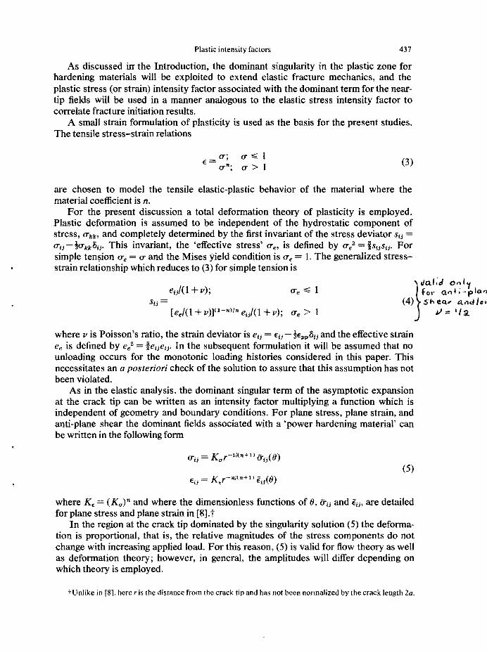
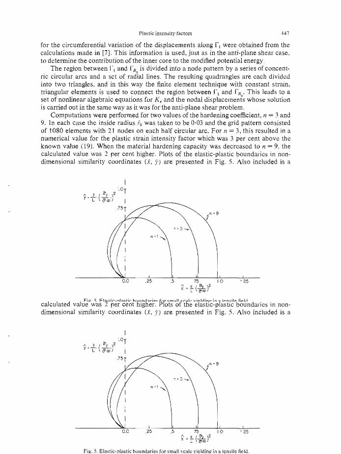
Computations were performed for two values of the hardening coefficient , n = 3 and 9. In each case the inside radius Po was taken to be 0·03 and the grid pattern consisted of 1080 elements with 21 nodes on each half circular arc . For n = 3, this resulted in a numerical value for the plastic strain intensity factor which was 3 per cent above the known value (19). When the material hardening capacity was decreased to n = 9, the calculated value was 2 per cent higher . Plots of the elastic-plastic bound aries in nondimensional similarity coordinates (x, 5') are pre sented in Fig. 5. Also included is a
I _ l'OT
1\ , .1...12)2 Y L \ 5 (I) I
75 T
.25 .5 75 10 125 1\ : z. (!!:L)2x L ?yO>
calculated val:~ <JvJa~1 2<t~e?l ~c~~thlg'h~e~ < p1oy; o~rihle '~t~.iitic~pl~ti2 "bRot~d aries in nondimensional similarity coordinates (x, 5') are pre sented in Fig. 5. Also included is a
I _ l'OT
1\ , .1...12)2 Y L \ 5(I) I
75T
.25 .5 75 10 125 f'o : z. (!!:L)2x L ?yO>
Fig. 5. Elastic-plastic bound aries for small scale vieldinz in a ten sile field.

448 P. D. HILTON and J. W. HUTCHINSON
sions for <b and tjI which satisfy the symmetry conditions about both axes for Iz I ;;;;. R, are
'" (f> = ~ ~m_lZ-2m+1 m=l
00
~ b z-2m+l ~ 2m-l
m=l
where am and bm are real. Outside rR, <P = <Po + <P and .p .po + tjI. The coefficients am and bm are related to the displacements along rR by
m= 1,3,5...
1T/2
R2rr'" 4R f---- (u+iv)e- 18 dO (23)6 31T o
1T/2
bm=R2(m-2)am_2-4~m f (u+iv)e- i m6 dO m 3,5,7... o
The procedure from here follows that for the anti-plane shear problem. The contribution from A 2 to the modified potential energy functional is written in terms of the coefficients am and bm which are in tum related to the displacement field along rR
through (23). The dominant singular solution discussed for small scale yielding is used to describe the solution on and within the small circular arc fl' Its amplitude, K E, is to be found through the minimization of the modified potential energy functional. The region between f l and f R is divided into a triangular grid pattern and the finite element technique is employed to connect the singular solution to the far field.
The computations for the large scale yielding problem were performed with a grid consisting of 1066 elements and an inside radius To of two percent of the half crack length. The calculated values for the plastic strain intensity factor in the large scale yielding range associated with this grid are expected to be low by several per cent paralleling the findings for anti-plane shear. A check was made on the assumed condition of loading inherent in this formulation. Careful examination of the solution over the range of the loading parameter investigated here indicated that with monotonically increasing values of the load parameter, the stress invariant everywhere in the field also increased monotonically.
The results are presented in the same form as they were for the anti-plane shear problem. In the large scale yielding range, the plastic strain intensity factor is KE = [f(rrOOW anJ( n + ll , while the formula for the plastic strain intensity factor for the small scale yielding problem is given by (7). In Fig. 6(a). A(rrOO KE/(KE)s.s. s, is plotted (
against a" "" iJoo/Uy. The modifiedformula for the crack initiation stress is
1
and plots of rrloo/rry vs. K~l/rry v;a are given in Fig. 6(b) for n = 3 and 9. The elastic-plastic boundaries corresponding to the above calculations are exhibited
in Fig. 7. At an applied stress level of half the yield stress the maximum extent of the
i

449 Plastic intensity factors
1.3
1.2
J5..s.. 1.1
(K.)s.s.y 1.01-----.-=:::.::::;-
.9
o
Fig. 6(a). The plastic strain intensity factor as a function of the applied stress for tensile loading.
io
.8
.4
.2
-c ~ _1_
'i'y .fTi'O
Fig. 6(b). The critical initiation stress for large scale yielding, tension.
elastic-plastic boundary is already greater than 40 per cent of the half crack length. Even so, elastic fracture mechanics, which is based on the dominant singularity of the purely elastic solution, still gives quite accurate predictions for the critical initiation stress at this level of applied stress.
The present predictions are now compared with predictions for fracture initiation based on two perfect-plasticity models. The first, due to Irwint, is a semi-empirical adjustment of the elastic stress intensity factor to take into account the size of the plastic zone. Irwin makes use of the plastic zone size predicted for the perfect-plasticity, anti-plane shear problem and argues that the effective crack length is increased by an amount comparable to the size of the plastic zone. For the present problem, Irwin's suggestion for the modifiedelastic stress intensity factor is
The predictions for the critical stress based on this are included in Fig. 6(b). Irwin's formula is quite good for low hardening materials over the range of the loading parameter plotted.
f Private communication, see also [1].

450 P. D. HILTON and J. W. HUTCHINSON
liIL
Fig. 7. Elastic-plastic boundaries for a crack subjected to a remote field.The half crack length is unity and the crack tip is taken at s = O.
The Dugdale-Barenblatt model, for the perfect-plasticity treatment of necking ahead of the crack tip in thin sheets of certain metals, is the basis of the second comparison. The crack opening displacement, the separation which occurs between the top and bottom faces of the crack at the tip, as predicted by this model[2] is
0= ~ £y log [sec (0''''' I)]' (24)
The associated fracture initiation criterion for a sequence of sheets with identical thicknesses is that the crack opening displacement reach a critical value oC. For small scale yielding this criterion leads to
2.4
2.2
2.0
1.8
1.6
Y 1.4
L 1.2
1.0
.8
.6
.4
.2
0 2.0 2.2 2.4 2.6
Where there is no restriction on the applied stress, the critical stress is given by (24) with 0 identified with OC. The resulting predictions fall between the present results for n = 9 and those from Irwin's formula.
Rice [2, p. 293] has discussed the extension of fracture mechanics into the large scale yielding range using results from the anti-plane shear problem as well as from the

451 Plastic intensity factors
Dugdale-Barenblatt modeL Instead of emphasizing the plastic intensity factors, he uses the value of a path independent integral defined for deformation theory as a measure ofthe level of deformation at the crack tip. It can readily be shown that these two approaches lead to identical results as long as a deformation theory of plasticity is employed. The present approach which accents the use of the plastic intensity factors is not restricted to use of a deformation theory as has been discussed and may, for this reason, be somewhat more attractive.
SUMMARY The initial fracture predictions from classical fracture mechanics for cracked sheets
in tension are quite accurate for applied stresses up to approximately half the yield stress, even though at half the yield stress the elastic-plastic boundary has been distorted considerably from that associated with the small scale yielding solution. For cracks of shorter length which fracture at higher stress levels, the critical initiation stress is found to deviate more from the small scale yielding predictions as the strain hardening capacity is reduced. Very similar conclusions follow from previous work on the anti-plane shear problem.
The method developed here for combining the knowledge of the dominant singular solution with the finite element technique to obtain accurate solutions in the neighborhood of the crack tip is also applicable to the treatment of problems involving cracks in finite bodies. It is for unusual geometries that the finite element technique is particularly attractive. The application of these techniques to the calculation of elastic stress intensity factors is straightforward and has been carried out for each of the problems considered in this study.
REFERENCES
[1] F. A. McClintock and G. R. Irwin, Plastic aspects offracture mechanics. ASTM Spec. Tech. Publ. No. 381,84(1965).
[2] J. R. Rice, Mathematical analysis in the mechanics of fracture. Fracture Vol. II, pp. 191-311. Academic Press, New York, (1968).
[3] J. A. Hult and F. A. McClintock, Elastic-plastic stress and strain distribution around sharp notches under repeated shear. Proc. 9th Int. Congr. Appl. Mech., Brussels. Vol. 8, pp. 51-58 (1956).
[4] H. Neuber, Theory of stress concentration for shear-strain prismatical bodies with arbitrary non-linear stress strain law. ASME 83-E, 544 (1961).
[5] J. R. Rice, Stresses due to a sharp notch in a work hardening elastic plastic material loaded by longtudinal shear. J. appl. Mech, 34, 287-298 (1967).
[6] J. R. Rice and G. Rosengren, Plane strain deformation near a crack tip in a power-hardening material. J. Mech. Phys. Solids 16, (1968).
[7] J. W. Hutchinson, Singular behavior at the end of a tensile crack in a hardening material.J. Mech. Phys, Solids 16, 13 (1968).
[8] J. W. Hutchinson, Plastic stress and strain fields at a crack tip. J. Mech. Phys, Solids 16,337 (1968). [9] P. C. Paris and G. C. Sih, Stress analysis ofcracks. ASTM Spec. Tech. Publ. No. 381,30 (1965).
[to] W. F. Brown and J. E. Srawley, Plane strain crack toughness testing of high strength metallic materials. AS1'M Spec. Tech. Publ. No. 410 (1966),
[tl] 1.S. Tuba, private communication. [12] G. Fix, Higher-order rayleigh-ritz approximations, J. Math. Mech. 18,645-658 (1969). [13] O. C. Zienkiewicz, The Finite Element Method in Structural and Continuum Mechanics. McGraw
Hill, New York (1967). [14] B. Budiansky, Extension of rnichell's theorem to problems of plasticity and creep. Q. appl. Math. 16
307-309 (1958). [15] N. I. Muskhelishvili, Some Basic Problems of the Mathematical Theory ofElasticity. N.V.P. Noord
hoff Groningen, Holland (1963).
(Received 10May 1969)

![Classical Mechanics - people.phys.ethz.chdelducav/cmscript.pdf · References [1]LandauandLifshitz,Mechanics,CourseofTheoreticalPhysicsVol.1., PergamonPress [2]Classical Mechanics,](https://img.pdfslide.net/doc/110x75/5e1e9832bac1ea74484e9601/classical-mechanics-delducavcmscriptpdf-references-1landauandlifshitzmechanicscourseoftheoreticalphysicsvol1.jpg)