Embed Size (px)
Citation preview


Welded Conti,nuous Frames and Their Components
PLASTICANALYSltS' OF, C'UR'VED KNEE,CORNER _C.ONNECTIONS
by
John W$ FisherGeorge Co Lee
George Co Driscoll, Jr@
This work has been carried out as part of an: investi~gation. sponsored jointly by the Welding~ Research Counciland the Department of the l'favy with funds furnished b,Ythe following:
American Institute of Steel ConstructionAmerican Iron and Steel Institute ,Bureau of Ships
Reproduction of this report in whole or in part ,ispermitted for any purpose of the United States Govern~mente
. Fritz Engineering LaboratoryLehigh' University
. Bethlehem,. Pennsylvania
'. October 1961
Fritz 'Engineering: Labor~tory;ReportN00 205C~26

ABSTRACT
~
) A method is presented for,analyzing connections with\
curved inner flanges commonly used in rigid frame construction.
The method is based on simpl~ plastic theory. The bending
capacity: and the stability of the connection are considered.•
Also, the effect of cross=bending of the .flanges, shear, and
axial force is discussede
Design procedures for proportioning a connection with
a curved inner flange are presented. The design of the
stiffeners is included~ Examples illustrating. the design
method are presentede

TABLE OF CONTENTS
l~
A-BSTRACT
INTRODUCTION
PLASTIC ANALYSIS
1
2
2.1 Solution by Simple Plastic· Theory 2
2~2 Location of Critical: Section in a·Curved Knee h
2.3 Influence of Shear and Axial Thrust 6
3 ~ STABILITY OF, THE COMPRESSION -FLANGE 7
3.1 Lateral Buckling of the Compression Flange 7
3.2 Effect of Warping 11
.3~3 Radial Stiffener in Curved- Knees' 13
4e DESIGN,RECOMlVIENDATIONS ANDILLUS·TRATIVE EXAMPLES 16
4~1 Recommended Design Procedure 16
4,,2 Design Examples 18
5 ~ SUIVJMARY' AND CONCLUSIONS 21
6& ACKNOWLEDGEMENT .23
70 NOMENCLATURE 24
8. FIGURES 26
9. , REFERENCES 33

2050.26 -1
l~ INTRODUCTION
It is the purpose of this study to present a plastic
method of analysis for connections having curved inner ,flanges.
A detailed description of haunched connections with straight~
tapered knees and a review of related literature may be found
elsewhere(l).
The sequence of analyzing various aspects of a curved
knee is as follows. A solution is first obtained based on
simple plastic theory, in which the most critical section
within a curved knee is determined. The influence of shear
and axial force on the plastic solution is then discussed.
Also, the stability of the compression flange is treated; the
relationships between the maximum unsupported length, the
thickness of the compression flange, and the geometry of the
knee are analyzed. Finally a recommended design procedure: is
presented, and design examples are given.
,The theory developed 'in this study has been verified
experimentally(2). The observed results ~howed good agree-
ment with those predicted by the theories presented herein.

2G PLAST~C ANALYSIS
This section presents a plastic method of analysis for
connections having curved· inner flangesa A typical connec-
tioD. is shown in Fig. 1. A solution based on, simple pl~stic
theory is developed fir8t~ ,The location. of the most critical
section. within. the haunch is obtained, bT~aximizing the
solution~ The influence of axial force .and shear on the
plastic _-;solution. is also, treated ~
,Solution. by Simple Plastic Theory
The assumptions and conditions upon which this analysis
is based are as follows:
1. Plane sections remain. plane ·after bending;thu~ the
bending strains are proportio~al to the distance
from the neutral axis.
2. The idealized stress-strain diagram. is assumed, and
the behavior of fibers in bending is the same ,as in
. compression, and tensiono
3. ,Equilibrium.between the applied loads, and moments and
the resulting stress distribution. exists in order that
Normal force: P £'C-y dA . (;1)
Moment~ M = j cryyd!dA ( 2)A
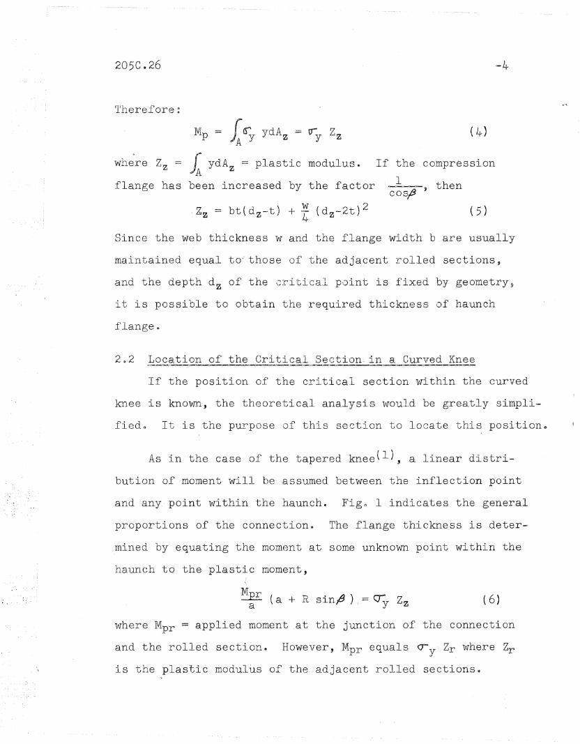
4. The forc~ in the curved flanges. is approximately
uniform,. along, its length. ,( Since the depth of the
haunch increases rapidly after f9 is greater than 718
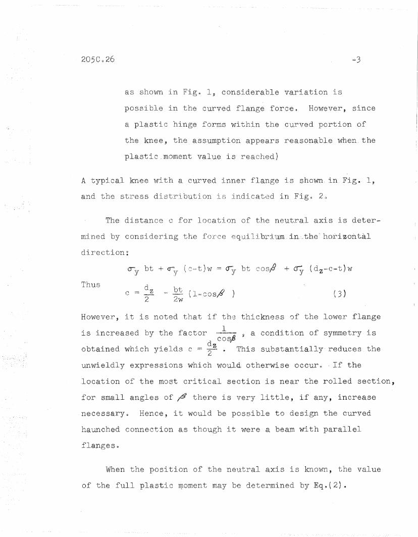
as shown in Fig@ 1, considerable variation is
possible in the curved flange force~ However, since
a plastic hinge forms within the curved portion of
the knee j the assumption appears reasonable when. the
plastic.moment value is reached)
A 'typical knee with a curved inner flange is shovm. in Fig. 1,
and the stress distribution is indicated in Fig. 20
The distance c for location of the neutral axis is deter-
mined by consider~ing t118 for'ce eq'ui.libl~:lcum,;in.:,.the~horizonta.l
direction:
Thus d z2,
lJt, ( .IJ ),= ='= ',l=cosr'
21/1T( 3)
However, it is noted that if the thickness of the lower flange
is increased by the factor ~ ~ a condition of symmetry isd cos,..,
obtained which yields c = T. This substantially reduces the
unwieldly expressions which would otherwise occuro ,If the
,location of the most critical section is near the rolled section,
for small angles of ;9 there is very little, if any, increase
necessary@ Hence, it would be possible to design the curved
haunched connection as though it were a beam with parallel
When the position of the neutral axis is known, the value
of the full plastic l1).oment may be de"term.ined by Eq~( 2) (J
If the compression
1 ,thencosj3
rr11erefore:
M = rcr ydA = IT: ZzP )A Y z Y
where Zz = ~ ydA z = plastic modulus.
flange has been. increased by the factor
(-4)
Since the web thickness wand the flange width b are usually
maintained equal to·' ·those of the adjacent rolled sections,
and the depth d z of the critical point is fixed by geometrys
it is possible to obtain the required thickness of haunch
flange &
2~2 Location of the Critical Section. in a Curved Knee
If the position of the critical section within the curved
knee is known, the theoretical ana,lysis WQu.l.d be greatly simpli.
fiedG It is the purpose of this section to locate this position&
As in the case of the tapered knee(l), a linear distri-
bution of moment will be assumed between the inflection point
and any. point within the haunche Figo 1 indicates the general
proportions of the connectione The flange thickness is deter~
.mined by equating the moment at some unknown point within the
haunch to the plastic moment,
( 6)
where Mpr = applied moment at the junction of the connection
and the rolled section. However, Mpr equals cry Zr where Zr
is the plastic modultis of the adjacent rolled sectiorts~

Hence:
or'
sily9 )= u y GtE d ~t)+R(1-cosl )J + ~ ~ d - 2 t ) +R(1-C0S!~~)d+R( 1-cos;9) ~ I /d+R( l~co.. eI) .2 (b~W) 4Zr( a+R sir}6')
t. = ~~~_~~V~l~~~ ~_~ ~-=a~(~b~·<:'"':"~w......,,)_____2 (7)
It is PQssible to maximize the thickness of the haunch flange
wi th respect to the ·angle ;J 0
Th1.lS :
If values of a and R are assumed for typical connections, it is
possible to plot the rate of change of thickness with respect
to the ,angle ~ for various sizes of rol~ed sectionso _The values
of d,_ b, w, and Zr in, Eq~(g) are those of the rolled sectiono
A plot of EqG(8) is shown in Fig~ 3~ Since the thickness t is a
m.aximum when zero slope is approached from, a positive sen'se, the
critical angle is ap~roximately 12 deg$ Values of a and R used
in the computations for the curves in Fig~ 3 are indicated.
Except for unusual cases where shear is very large, it is con
sidered that the critical section can always be taken atl = 12 deg.
If the angle of intersection. between the girder and column
is increased, the assumption of a linear moment diagram between
the points of tangency and the critical section. will not be
affectedQ Therefore, the critical section for rectangular and
gable £r~me knees w~ll always be approximately 12 deg~ frOID. the
points of tangency~

Test results of various curved knees having a variety of
proportions have all seemed to indicate that the critical sec-
tion is within thei,mmed~iate vicinity of a point ;12 deg. from
the point of t f ngencY0 It is therefore concluded that this is
a reasonable solution. Also, since the critical angle f1 is
so small, the compression flange only' needs to be increased by
the factor lo02~ For all practical purposes this can be
ignored, and hence the required thickness of the haunch flanges
can be readily obtained~
2:~ 3 Influence of Shear _and Axia.l Thrust
Since the area of a section within, the haunch is always
greater than a comparable section, in the adjacent rolled
section, it may be concluded that the effect of the axial
force ,and the shea.r in the knee wil.l be less critical than
in the rolled section0 Also~ previous tests ~ave shown that
shear has little influence on the ~aximum bending strength of
most structural members(3). Thus, as long as the critical
section~._±s equal to or grea~er than the rolled section, the
effect of axial force and shear may be neglected.

205C~26 -7
3 ~ STABILI-TYOF THE .C.OMPRESSION~, FLANGE
If a connection is to develop its fully plastic capacity,
pre~ature failure due to stability considerations must be pre
vented. Both local and lateral stability are treated in this
section.
3.1 Lat.eral. Buckl.ing of t.he Compression.,.,Flange
Due to the curved shape of the compression flange the strain
energy approach was useda The strain energy of lateral beriding
was equated to the work done by the flange force when deformation
occurSe Before formulating the energy of the system, it is
necessary to state the conditions and assumptions madelt
l~ The curved compression flange buckles independently of
the re~aining component parts of the cross sectiono The resistance
to buckling offered by the adjacent" web is assumed negligibleo
20 The curved flange is assuroed to have a uniform stress
distribution corresponding to the yield stress over its area
and is assumed to have reached the strain-hardening state along
its length.
3. The compression flange is simply supported at its
connection with the roll~d~~section.
4. The flange must buckle normal to the plane of the
haunch. (Twisting is assumed not to occur in the compression
flange because of the restraint of the web. A solution which
includes the effect of twisting is contained in Timoshenko's
Theory of Elastic Stability, p~ 2$5)

5s The forces restraining the flange from buckling in
the plane of bending are transmitted by the web~ It is
assumed in the derivation that the directions of the loads
do not change during buckling, and that they are displaced
laterally only, thus remaining parallel to their ftiiti~l
directiolle Hence, no work is performed by the forces re~
straining the flange during, this translation.
The general case of the curved flange is shown in Fig. 4.
From the assumption of simply supported ends the deflection
curve of the slightly buckled flange may be expressed by the
equation
.~Y = Sln Ro(
where s is taken as the arc length
The displacement of the load P during buckling producesI
Hence
the corresponding wor~·lid 2
T = - (~ds. 2 -1, d s
T= P (~) 2 IR;< 2 'ITs d
2 Rot _B£< cos RD' S2
(10)r
Likewise, the
p (JI) 2 .Re<(11)- .~
2 Ro( 2
corresponding energy of bending- U is'" given by
Estlx IS d 2 2~ (12 )U 2 ( ds 2 ) ds
0

-9
Hence pRo(
Estlx '\Ir 4 1 sin2 1'r SU = 2 ( RC<) Ro< ds
0
EstIx 11 4 Ro{2 (Ro( ) () 2 (13)
The critical value of the load at which e,quilibrium changes
from stable to unstable with respect to lateral buckling in the
strain-hardening range is determined from the equation
Hence
. U:~ T (14)
(15)
Since Ix = r x2 Af and P = cry Af , the critical length of the
curved flange can then be expressed as
(16)
The strain-hardening modulus Est will be taken.as 900 ksi(4).
Hence,. Eq.(16) can now be expressed as
16.5 (17 )
Since
Then
fflx 1 tb3 br=-==-~--=-
x ,Af tb 12 -(i2
(1,8 )
For square-corner curved knees used in portal frames.a maximum
all.owable radius of the curved flange may be formulated $ If

~lO
lateral support is provided at points A, B, and C in Fig. 5,
it can be assumed that the compression, flange is forced to
buckle in the second mode$ Hence, the critical length can
then be expressed 'as
R : = 4.8 b
T11erefore, the rp.ax i mum ,allowable radius of the curved inner
flange isR = 6b (19)
A larger radius may be permitted if the number of points
of lateral support is increased or the magnitude of r x is in
creased in.Eq.(17)* The radius of gyration can· be increased
by widening the co~pression flange or incorporating a,special
shape which will greatly increase rx~ It is also possible to
increase the flange thickne?s to achieve stability when. a radius
larger than 6b is desirable. It has been shown(l) that the in-
cy'ease in flange thickness A t required- for, any radius. is
Therefore
At ( 20)
(21 )
where t is the flange' thickness determined from· EqoC-7) using
the critical dimensions of ~ = 12 0 and R = 6bo
For knees used in gabled frames it wi,ll be necessary ~o
determine the angle ~between,the points of lateral support2
before t,he critical buckling length and hence the maximum

-11
a,llowable l~adius can 'be obtained. However, it can be seen
from Figffi 6 that the angle '" will a.lways be less than 1\ in2 .4
gabled framesril Tl1us the maximum a,llowable radius will: be
gY'eater" than t1:lat allowed for' knees whose members inte,rsect
at right angles;)
One of the important assumptions made in the previous
sectiDn was that the fiber stress along the curved flanges
was approximately at the yield value throughout its length.
This stress produces a radial cowponent, which tends to bend
the curved flange across the web plate* This problem was
recognized in the elastic analysis of curved flanges, and a
solution was developed by Bleich(S). It was realized in
elastic analysis that the transverse displacement of the flang~s
could greatly influence the distribution. of longitudi~al stresS
over the cross section (ll Therefore., when the plastic analysis
of a curved knee was considered, it was felt necessary to· in-
vestigate the effect of this phenomenon on the full plastic
moment and geometry of the section.
In order to complete the analysis, it is first necessary
-to calculat.e the ~agnitude of the transverse forces acting
in,the curved flange of the knee. From the first assumption
in Section.3~1 the force in a fiber of unit width with radius
of curvature R becomes 0;t. From, Fig$ 7, the tra11sverse force
in the length dp becomesI;
p= a; t do(. (2'2 )

205C.26
The transverse force per unit of length is
L _ do< = o;tds - a; t ds """'"R ( 23)
-12
A strip of flange having a unit width and a length Of~ can
then be subjected to this uniform transverse force as shown
in.Fig~ 8~ This can be examined as an approximation, of the
true behavior of the compression flange of a curved knee when
subjected to forces tending to close the knee$ . It is assumed
that the symmetry of the section causes a strip of unit width
of the flange to act as a cantilever rigidly fixed~at the
base and subjected to a uniform load ofa;t •=-r
From, Figo 8 the maximum moment is
= cL.1 b2
M y R 8
The plastic modulus of a one~~nch strip of curved flange
ass'urnes the value
Z ==
The· limiting value of the warping stress, which is equal
to the yield stress, can now be equated
or
Hence~
. ~t 2() = M = Uy b
y. Z 8R
~. = ayb2
y' 2Rt
< 2
4· :2t
( 26)
(27)

-13
It is interesting to note that Eq8(27) corresponds identi~ally
with Rule 7 presented by Griffiths ( 6) in his "De sign Rules"
for the proportioning of rigid frawe'knees~ One other point
"LO note is that, this critica,l conditioD is maximum only, at
the junction of fla~ge and web. The transverse stress varies
from zero on the flange tips to the assumed maximum. value cry'
3.3 Radial Stiffeners ~n Curv~d Knees
It was recogn'ized in elastic design that it was desirable
to provide stiffeners at the mid point and at or near the
extremities of a curvedknee(6). It is evident that they
should be used also in plastic design to prevent undue shear
deformation and premature web buckling~ Unfortunately, no
flpl'8cise" ma~thematical or empirical solution exists for the
design of such members~ It is not proposed in,this section
to present a rigorous mathematical solution to this problem~
The analysis and rules presented ,are an approximate means of
tietermining the required stiffener,area.
The following assumptions are ~ade:
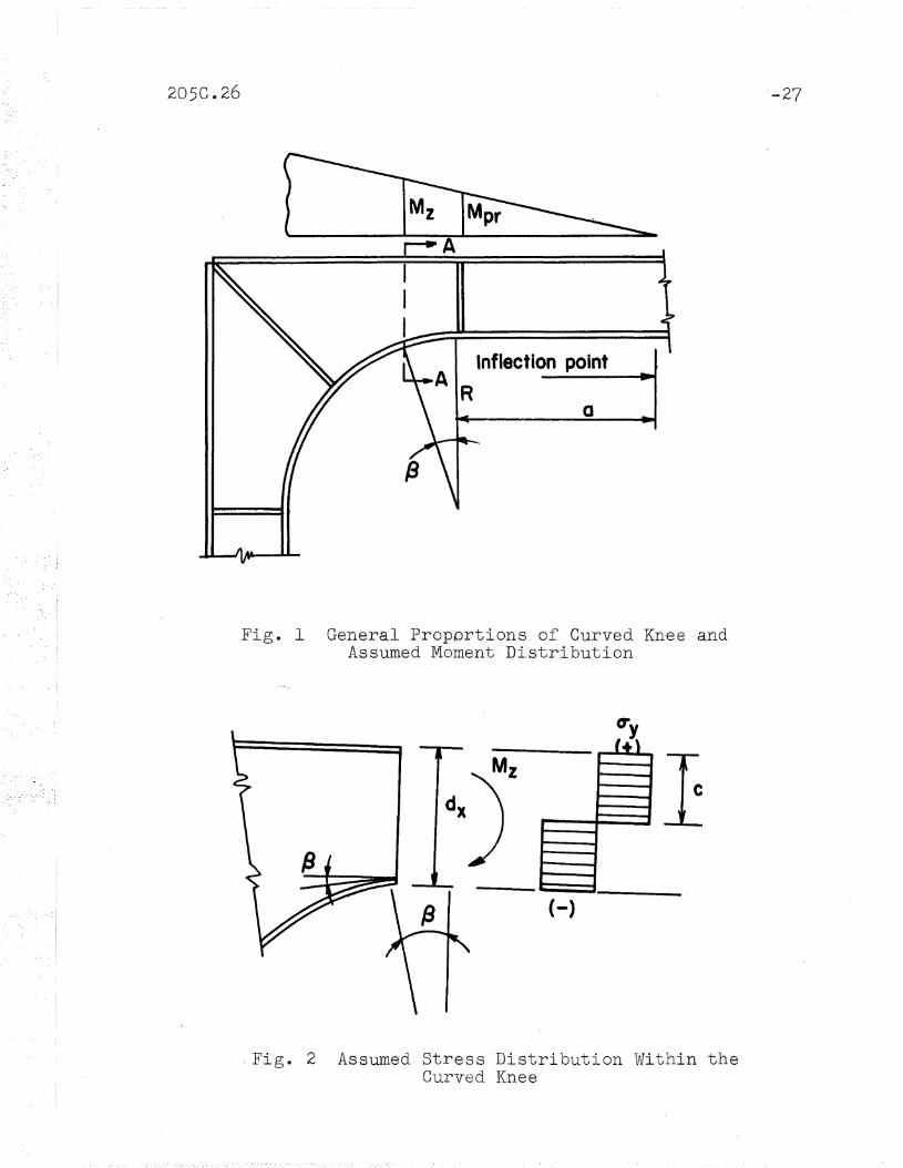
1. The diagonal stiffener at the corner must resist a
force due to the curved flange.
20 The force transmitted is the component of a force
equal to the pla~stic ,flange force which passes through the
midpoint of the curved flange and the points of tangency at
the rolled section (Figs~ 9 and 10) e

:-14
The above assumptions are ,arbitrary, but it is believed
that they result in a conservative solution@ The actual forces
transmitted by the curved flange into the diagonal stiffener
are no doubt much smaller since much of the ra.dial force is
taken by the web of the haunch~ However, it is desirable to
have sorne way of proportioning the diagonal stiffener, which
is pri~arily used to prevent the haunch, web from,buckling.
For a rectangular portal frame having'a curved inner
flange as shown in Figo 9, the required. stiffener thickness
is determined as follows. The force Fs acting on the diagonal
stj~ffener is, from assumption 2, equal to
The required stiffener area is then obtained asFsoy
If the width of the stiffener is maintained the same as the
width of the ~aunch flange" the required stiffener thickness
becomes
(30)
Generally, for ease in fabrication and as"a matter of practi-
calitY9 the stiffener could be cut from material'with the
same thickness as that of the flanges.
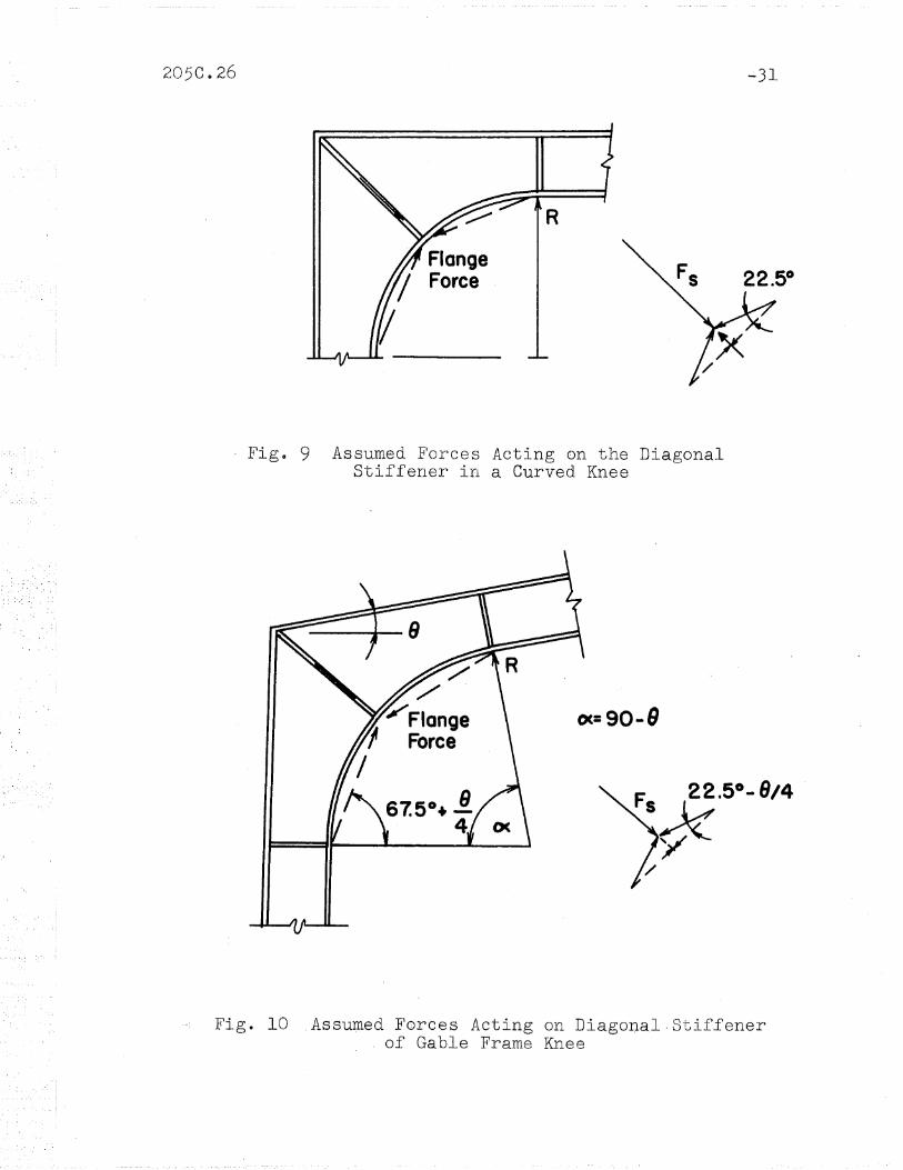
For connections proportioned for use in gabled frames in
which the girder intersects the column at an angle larger than
'. ,} I

205C.26
a right angle,. the following!~o~ution for the required
-15
stiffener thickness is obtained. The component of the flange
forces resisted by the diagonal stiffener can be obtained. from
Hence,Fs = 2 cJy Af sin (31 )
Thus, the required stiffener area is
1As = 2Af sin (22. 50 - 4 e )L I
(32)
Again, this can be simplified further by making the stiffener
width the SalJl8 as the haunch, flanges. The required. stiffener
thickness that is obtained is1
t s = 2t sin ( 22 • 5 0 - 4 e ) (33)
For most gabled frames of practical, proportions such that the
roof pitch is not excessive, the influence of the gable angle can
'be Yleglected.

4 e DES1GN, ,REC,0IVJMEND,ATIONS AND, ILLUSTRATIVE EXAMPLE-S
The recoll1mendations pl'lesented here were evolved from
the preceding sections. The examples are included to illus-
trate the application of the design. procedure to a hypotheti-
cal cases
4 at 1 Rec_Q:rnm.en-de,d, .Design P~ocedure
A curved knee way be proportioned on the following basis:
lQ The critical design sections are taken at the points
of tangency and at sections 12 dego from the points of
tapgencyQ
28 The size of rolled section required ,at the points of
tangency would be selected by simple plastic theory. The
flange width and web thickness of the haunch is usually main-
tained the same as in the rolled section~
3$ The required flange thickness of the inner'and outer
flanges at the critical·section 12 deg. within the haunch can
be determined by Eq. (7) 'r----------
t dz -l/dz2(~)
2
where the dimensiops and moment'Mz are taken,at ~he critical
section.
4e Because of local buckling the value of t must be .such
that ~ does not exceed 17(7).
5~ The maximum allowable radius of the curved flange
for a rectangular portal frame knee is R = 6b when positive

-17
lateral support is provided for the compression (curved)
flange at the midpoint and at or near the points of tangency.
If it is desirable to increase the radiu,s of the curved flang.e.,
more lateral support must be provided such that the 'arc length
between support points does,not exceed 5b. Another methode of
increasing the radius without increasing the points of lateral
support is to increase the radius of gyration, of the curved
flange so that
(~o() = 16. 5x cr
,,;.
If it is undesirable to provide intermediate points of support,
the thickness of the flanges within the haunch can be in
creased to control, the strains by util,izing, Eqs$ (20) and (21').
6. For knees in gabled frames, where ~ is the angle be-
tween, the points of lateral support g the maximum allowable
radius can be found from Eq~ (1~0
7 (f The relations'hip between the width of the cu,rved flange
to its thickness must such that
b2-<. 1
2Rt
~f this is exceede~, it is"necessary to increase the thick-
ness of the flange or to provide short, stiffeners along the
Cl1101 ved flange-.~
. g~ Stifferiers should; be-provided at the ~idpoint of the
curved flange :and at ;~r -near the points of tangency. TheI.~ :, ,.<_,_
,stiffener at, them~dp6int which- connects the point of inter-
section of the two outside fla~ges with- the midpoint of the

20 5C.v 26 -18
curved flanges should be proportioned so that the minimum
area of the diagonal stiffener is three~fourths of the
£lange ·area. Generally though, for ease in fabrication and
as a matter of practicallity~,the stiffener can be made the
same thickness as the haunch flanges. The stiffeners at the
points of tangency can be of nominal size.
4$2 Design .Examples
The design procedure developed in this section can be
illustrated by using two examples, one a connection for a
I'ectangular portal frame and the other for a gabled frame.
Consider first the design of the curved knee in FigG 11.
In the assumed loading condition ,a plastic hinge forms
at A, the point of tangency~ Lateral support will be pro-
vided at the midpoint of the curved flange .and at, the points
of tJangency wi th the rolled section; there.fore, the waximum
allowab~e radius that is permitted is
R = 6~= 6(8) == 48 inG
The plastic modulus requ~red at point B is
Z == ~ == 1900( 40+48 pin 12°) == 72.0 · ,3cry 33 40 In.
The required thickness of the haunch flanges at B then· be-
COlues13.0 .-
0.635
(8.0 4(71.2)8.0-0.294 ~ 8~O~O.294
2

According to ,procedure 7
b 2t > ~-
2R
:> 82
t - 2( 48)
-19
Therefore increasing the thickness of the curved flange is
necessary11
Use 16 in. Plate (0.69)
The diagonal stiffeners can be proportioned so the stiffener
area is three~fourths of the flange areaa
lienee,
In view of the above required stiffener area, all radial
stiffener requirements can be provided by ~ ift.Jplate.
The second design example will be a curved knee for a
gabled frame (t It will. again be assumed that the prismatic
sections have been, selected so that the plastic binge condi-
tion occurs at the point of tangency of the knee. The knee
to be designed is shown in Fige 12~ From the loads and
moments it is apparent that the critical section in the haunch
occurs at 12 deg. from point A~ Lateral support is provided
at :points A, 0, and D~ Hence, the maximum allowable radiusI
lJ8 comes 5b 5(10.0)Rcr = c< 0064
,= 78 in.
The radius used was
R == 72 ins < 78 ,in~

-20
According to procedure 3 the required flange thickness of
the haunch at point B is
t.= dz ~ 'Jdz2(~)
2
Since
MZz = c1 = 9930 = 301 in3
y 33
and
the thickness of the flange isI
t
2
= 0076 in. (Use ~~ in. Plate)
Next, from procedure 7
bt
2Rb
10 <=2(72)o:rro = 10
Thus the thickness provided is sufficient.
According to procedure 8 the radial stiffeners.at the knee
centerline and the points of tangency are considered. The
required stiffener thickness is three~fourths of the flange
thickness for the diagonal stiffener. Hence,
(Use i6 ino Plate)·
The stiffeners at the points of tangency will be arbitrarily
made of the same materia10

2050026 -21
58 SUMMARY AND CONCLUSIONS
A- method of proportioning curved corner connections based
on simple plastic theory has been presented~ The method is
much simplier than any kno~m elastic solution0 The solution
presented also considers the buckling characteristics of the
component parts of the connection as well as the- bending
strength~ The following summarizes the results of this
theoretical study of curved haunched connections:
l~ It has been shown tha.t haunched corner connections
with curved inner flanges may be analyzed by the plastic
bending theoryo The steps for proportioning curved haunched
connections are given in Section 4@lo
2~ Previous work has shown that failure of a built~up
haunch has been through lateral buckling of the compression
flange, even though adequate bending strength is provided.
Plastic bending theory is based on the precepts of a structure
stabilized against buckling. Therefore, a method has been
developed for assuring sufficient rotation capacity such that
failure does not prevent the haunch from transmitting the re
quired plastic hinge momente
3. The influence of axial force and shear on haunched
connections can be considered in the same manner as for rolled
sections. Generally the same modification that is applied to
the adjacent rolled sections can be used~
4~ The critical section in the knee is located iat
~ = 12 deg.

5. The effect
b 2<::: ±.~=--
2Rt-,'
of cross bending can be neglected if
--22
6. A design. procedure has been formulated and design
examples presented.
It should. also be mentioned that a series of tests was
conducted on connections desigried and proportio~ed by the
procedures developed herein, and the results showed good
agreement(2).

205C.26 -23
6~ ACKNOWLEDGEMENT
This work was carried out in,the Fritz Engineering
Laboratory at Lehigh University. The paper is based upon
a thesis by John W~ Fisher which was submitted in partial
requirements for the degree of Master of Science in June 1958~
The work was done as part of a program on. Welded Continuous
Frames and Their Components, sponsored jointly by the Welding
Research' Councill and the United States Navy with funds
supplied by the American Institute of Steel Construction,
the American Iron and Steel Institute" and the Bureau of
Ships. Technical guidance for this project was furnished
by the Lehigh Project Subcommittee of the Structural Steel
Committee, Welding Research Councilo TIro T~ R~ Higgins is
Chairwan of the Lehigh Project Subcommittee. Dr$ Le' s~ Beedle
is director of the project~
The authors wish to express their appreciation to
Joseph A. Yura for his assistance in producing this report.

7$ NOMENCLATURE
a
b
c
d
M
M.P
Mpr
Area of cross section
= Area of one flange
= Area of stiffener
= Area of section. within the haunch
= Distance between inflection point and. end ofhaunched connection
~ Width of flange
= Distance from neutral axis to extreme fiber
= Depth of rolled section
= Depth of section. within, the haunch
= Strain-hardening modulus
= Force resisted by diagonal stiffener
Moment of inertia about· the x~axis
Bending moment
= Plastic moment
Applied moment at junction of the connectionand the rolled section
= Applied moment at section within the haunch
Normal force
p = Transverse force acting on the flange
R Radius of curved haunch
r x = Radius of gyration
s = Arc length: length of compression,flange
T = External work
t, = Thickness of flange

-2p~
u
w
y
z
Thickness of compression flange
= Thic'kness of tension flange
Thickness of the stiffener
:=: Strain energy of bending
Thickness of web
Vertical distance between a point on the crosssection and the neutral axis
Plastic modulus
= Plastic modulus of rolled section
Plastic modulus of a section. within. the haunch
= Central angle between points of tangency of thecurved connection .
Angle between end of curved connection and criticalsection within, the haunch
Angle of rise in gabled frame
Yield stress'1'
Stress in z~direction

8* FIGURES
205C.26
A
Inflection pointA R
a
Mz
Fig. 1 General Propprtions of Curved Knee·and_Assumed Moment- Distribution
1+\I ~
- l-
,--..I
.....
- --(-)
c
,Fig. 2 Assumed, Stress Distribution Within theCurved Kn.ee

.205C@26
0.2
o
0= 3.25d,R =6b
o 8813• 14WF30A 24WFI00o 36WF230
a =3.5d,R =4b
5 10fJ (degrees)
Fig$ 3 Rate of Change of Flange ThicknessWith Respect to Angle.·(3
II
III zI III II
.. I III II OCX ....
YI II
y =sin .".s, IIROC\ I
r
\ I,I
~b -IFig. 4 .Buc-kli.ng Mode of Cur\Ted Flange

205C.26 ~29
CV2= "./4
Fig~ 5 Square~C9rner Curved Knee S~owing~Pointsof, Lateral Support
e Points ofLateral Support
. Figw 6 Gable Frame Knee Showing Points ofLateral Support

205C.26
r ds J________.7VZ l ---t: ~ c~7f
~Id Pcrzt
.-30
Fig. 7 Force in a Fiber of Radius ttRtt
b/2
y --:It .......... .... ----:)......
TP - CTztdi=ff
Fig. 8 Assumed· Loading on Curved Flange and ResultingDeflection
22.5°
205C.26 .;.31
Fig~ 9 Assumed Forces Acting on the DiagonalStiffener in a Curved Knee
oc=90-9
F 22.50 -8/4SsX/
Fig. 10 Assumed Forces Acting on Diagonal.Stiffener, of Gable Frame Knee

-32
Section Properties12WF40
A =11.77in~d=II.94in.b= 8.0in.t=O.516in.w=O.294in.z=57.6in~aa40.0in
R= 48in.
+47.5kips
r==========::=::::1) ..- 47.5kips
1--...............
-:::::::.;",............. 1900in...kips
205C.26
Fig. 11 Moment and Forces Acting on· Knee
74.1 in
~52.2kiPS~84.4kips
Section Properties27WF94
A= 2'l65in.2d= 26.91 in.b=9.99in.w=O.490io-t= 0.747In.z=2 77.7 in~3
Haunch web - I/2in.Haunch Flange width - lOin.
_.....-~ 8300 in- kips
65.5 kips f74.3kips .
Fig" 12 Moments clnd, Forces Acting on .Gable .Frame Knee
2050.26
,,REFERENCES
-33
10 Fisher, J~ W~, Lee, GG c., ,and Driscol1 9 G.. C. Jr.PLASTIC ANALYSIS OF TAPERED HAUNCHED CONNECTIONS,Fritz Engineering Laboratory Report. 205Ce25Lehigh University,1961
2. Fisher, Jo We' Lee, G~ C., and Driscoll, G. CG Jr.BEHA,VIOR. OF HAUNCHED CORNER, CON,NECTI10NS, Frit zEngineering Laboratory Report. 205Ce27,- LehighUniversity, 1961
! 3~ Beedle,- Le Se, Thurli~ann~ Bo,and Ketter, R~ L.PLASTIC DESIGN IN STRUCTURAL STEEL 9 1955 SummerCourse Lecture Notes,- Lehigh Uni\Tersitys 1955
40 Haaijer, G.)PLATE BUCKLING IN THE STRAIN-HARDENING RANGE,ASCE Transactions, Vola 124(1959)
50 Bleich, HG>. STRESS, DISTRIBUTION IN THE FLANGES OF CURVED T ANDI BEAMS, Navy Department, The David W. Taylor ModelBasin, Washington 7, DoC., January 1950Translation 228
'6. Griffiths, J~ D~
SINGLE SPAN RIGID FRAMES IN. STEEL, AISC, New York1948
7$ Baaijer, G., and Thunlimann, B.ON INELASTIC BUCKLING IN STEEL, Journal of the Engineering Mechanics Division" Proceedings ASCE. 84( EM-2)P~per 1581, April 1958