Embed Size (px)
Citation preview

Red: 0-100-100-0 Blue: PMS 293 100-56-0-0
Color Logo use on white background only
Black Logo use on white background only
White Logo use on black background only
Owners Manual
LH200Platform Hoist
4 color
TIE DOWN ENGINEERING • 255 Villanova Drive SW • Atlanta, GA 30336www.tiedown.com (404) 344-0000 Fax (404) 349-0401
TIE DOWN ENGINEERING • 255 Villanova Drive SW • Atlanta, GA 30336www.tiedown.com (404) 344-0000 Fax (404) 349-0401
Instructions #08100
010
312,
E122
5
• Lift Hoist 200 lb. Capacity• Quick Change Drum• Collapsible Carriage
Updated 1/3/2012
Tie Down Engineering • 255 Villanova Dr. SW • Atlanta, Georgia 303361
Congratulations on your Purchase of theTranzSporter Lift Hoist.
The TranzSporter Lift Hoist - Series was designed to last.
Features include...•CollapsibleCarriageAssembly•UnitizedDesign-Fewerparts,stronger,lessmaintenance•Non-SlipCarriageDeck-Saferoperation•HeavyDutyAluminumTrack-Absorbsmorepunishment•TetheredPushPin-Keepsdeckinplacewhentransportingorwhenoperatorisawayfrom thehoist.•DualBrakeSystem-Bettercontrol,longerbrakelife•Hi-ImpactNylonBeltGuard-Saferoperation•Ovenbaked,BlackPowderCoatFinish-Durable,longlasting•WideFootPlate-Bettercontrolofliftoperation•PermanentSafetyInformation-Combinationofstamped-insafetyinformationanddecal’sremind youroperatortousehoistinasafemanner•LargeSteelFootPads-Addsmorestability,lastslonger•ExtendedBrakeHandle-Keepsoperatorawayfromhoistwhenraisingorloweringmaterials
User Responsibilities
PERFORM THE FOLLOWING AT THE START AND END OF THE WORK DAY AND AFTER4 HOURS OF OPERATION DURING THE DAY:
•Checkoillevelinengineandfillaccordingtomanufacturer’sspecifications.•Checkcableforsmoothoperationandforsignsofwear.•Checkforlooseboltsandtightenaccordingtospecifications.•Checktracksectionsandallothermovingpartsforexcessivewearorfatigue.•Checkgeneralconditionofequipment.•Checkoperator’sunderstandingoftheproperoperationforthisequipment.•Checkextensioncordsandconnectionsforwearordamage.•Checkbrakepartsregularlyforwearordamage.•Checkcabledrumbearings,theyshouldrunsmoothlywhenthebrakeisreleased.Ifthereisanynoiseor ifthecabledrumdoesnotspinfreely,replacedrumbearingsimmediately.
WARNING: DO NOT OPERATE THIS EQUIPMENT IF ANY UNSAFE CONDITIONS EXIST OR OCCURDURING OPERATION.
Remember: Safety First!!
(404) 344-0000 • Fax (404) 349-0401 • www.tranzsporter.com 2
REPAIR INFORMATIONYourLiftHoistisdesignedtoprovideyearsofservice,however,whenyourhoistrequiresparts,serviceorrepairs,pleasecontactyournearestauthorizeddealer,orcall1-800-241-1806,ext.1525forinformationonwheretotakeyourplatformhoist.
WARNING:• KEEP TRACK SECTION CLEAR OF ALL ELECTRICAL WIRES AND EQUIPMENT• BE AWARE OF OVERHEAD OBJECTS• NEVER USE HOIST AS A LADDER• NEVER OPERATE HOIST WITH A HUMAN ON PLATFORM • NEVER STAND UNDER PLATFORM WHEN LOWERING• NEVER USE INDOORS OR IN AN AREA WITH POOR VENTILATION• NEVER USE HOIST TO LOWER MATERIALS
PLEASE READ!Theequipmentdescribedhereinhasbeenengineeredtoperformspecificliftingtasks,withaminimumofrisktotheoperator.Theinstructionsforoperationandsafetycontainedhereinweredesignedtohelpinsurethatthisequipment,performsitsfunction,asstatedwithoutaddingtotheendangermentofpersons,equipment,and/ormaterials.
LH200 - Series Specifications:200 lb. MAXIMUM Hoisting CapacityLH-Series-gasolinepowerunit-(4hp.LifanEngine,4hp.HondaorHighTorqueElectricMotor)Self-energizingbrake,3ft.steelbasesection,8ft.tracksections.
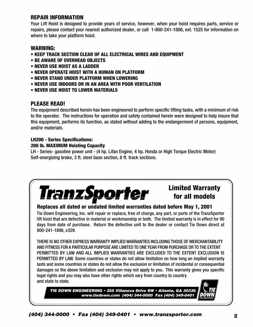
Replaces all dated or undated limited warranties dated before May 1, 2001 Tie Down Engineering, Inc. will repair or replace, free of charge, any part, or parts of the TranzSporter lift hoist that are defective in material or workmanship or both. The limited warranty is in effect for 90 days from date of purchase. Return the defective unit to the dealer or contact Tie Down direct at 800-241-1806, x329.
THERE IS NO OTHER EXPRESS WARRANTY IMPLIED WARRANTIES INCLUDING THOSE OF MERCHANTABILITY AND FITNESS FOR A PARTICULAR PURPOSE ARE LIMITED TO ONE YEAR FROM PURCHASE OR TO THE EXTENT PERMITTED BY LAW AND ALL IMPLIED WARRANTIES ARE EXCLUDED TO THE EXTENT EXCLUSION IS PERMITTED BY LAW. Some countries or states do not allow limitation on how long an implied warranty lasts and some countries or states do not allow the exclusion or limitation of incidental or consequential damages so the above limitation and exclusion may not apply to you. This warranty gives you specific legal rights and you may also have other rights which vary from country to countryand state to state.
Limited Warranty for all models
TIE DOWN ENGINEERING • 255 Villanova Drive SW • Atlanta, GA 30336www.tiedown.com (404) 344-0000 Fax (404) 349-0401
Tie Down Engineering • 255 Villanova Dr. SW • Atlanta, Georgia 303363
Safety instructionsCAUTION: Please read the safety warnings and Instructions contained in this manual beforeoperating the lift hoist. Failure to obey the warnings contained herein could result inpersonal injury or damage to the equipment; however, this information should not be a substitute for routine accident prevention, but rather an addition to routine accident prevention.
GENERAL SAFETY INSTRUCTIONS:1. Transportandhandleyourlifthoistwithcare.2. UnpacktheTranzSportercarefullyandinspectforanydamagethatmayoccurduringtransportation. DONOTUSETHEHOISTIFANYPARTISDAMAGED3. Pleaseobserveallsafetyandwarninglabelsattachedtothehoist.4. Useonlyreplacementpartsfurnishedbythemanufacturer.5. AlwayskeeptheareaaroundthebasesectionoftheTranzSporterhoistcleartohelpprevent slipping,trippingorfallingagainstthehoist.6. DONOTALLOWANYONETOOPERATETHETRANZSPORTERHOISTWHOHASNOTBEENTHOROUGHLY ANDPROPERLYTRAINEDINTHECORRECTOPERATIONANDUSEOFTHISHOIST.7. Thishoistismanufacturedtoliftmaterialsonly.Donotusethelifthoistforthepurposeof transportingpersonnelfromoneleveltoanother.8. Donotclimbthelifthoistoruseasapersonnelladder.9. Donotoverload-maximumliftingcapacityfortheLH200is200lbs.withaloadcapacityof180lbs.10. Keephands,feetandotherbodypartsaswellasclothingawayfromthetracksectionsandmovingor rotatingpartsofthehoistwhenstartingtheengineorwhenoperatingthehoist.11. Donotallowanypersonstowalkorworkunderornearthehoistwhileinoperation.12. Donotusethishoisttotransporthotasphaltoranyotherhotmoltensubstancefromone elevationtoanother.13. Storeallpartsofthehoistinsuchafashionasnottodamageanyofthecomponents.14. Donotoperateindoorsorinanareawithpoorventilation.
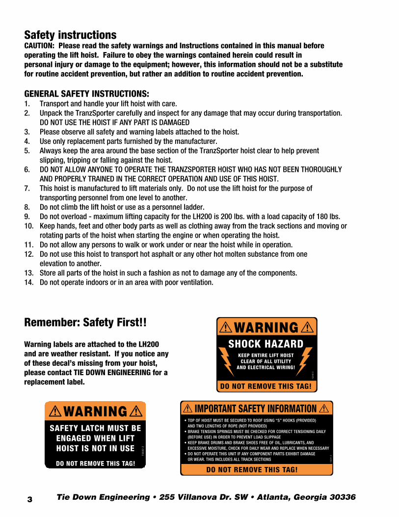
Warning labels are attached to the LH200 and are weather resistant. If you notice any of these decal’s missing from your hoist, please contact TIE DOWN ENGINEERING for a replacement label.
Remember: Safety First!!
1564
0-2
WARNING
DO NOT REMOVE THIS TAG!
SHOCK HAZARDKEEP ENTIRE LIFT HOISTCLEAR OF ALL UTILITY
AND ELECTRICAL WIRING!
1564
1-2
DO NOT REMOVE THIS TAG!
IMPORTANT SAFETY INFORMATION• TOP OF HOIST MUST BE SECURED TO ROOF USING “S” HOOKS (PROVIDED) AND TWO LENGTHS OF ROPE (NOT PROVIDED)• BRAKE TENSION SPRINGS MUST BE CHECKED FOR CORRECT TENSIONING DAILY (BEFORE USE) IN ORDER TO PREVENT LOAD SLIPPAGE• KEEP BRAKE DRUMS AND BRAKE SHOES FREE OF OIL, LUBRICANTS, AND EXCESSIVE MOISTURE, CHECK FOR DAILY WEAR AND REPLACE WHEN NECESSARY• DO NOT OPERATE THIS UNIT IF ANY COMPONENT PARTS EXHIBIT DAMAGE OR WEAR. THIS INCLUDES ALL TRACK SECTIONS
WARNINGSAFETY LATCH MUST BE
ENGAGED WHEN LIFTHOIST IS NOT IN USE
DO NOT REMOVE THIS TAG!15
642-2
1564
0-2
WARNING
DO NOT REMOVE THIS TAG!
SHOCK HAZARDKEEP ENTIRE LIFT HOISTCLEAR OF ALL UTILITY
AND ELECTRICAL WIRING!
1564
1-2
DO NOT REMOVE THIS TAG!
IMPORTANT SAFETY INFORMATION• TOP OF HOIST MUST BE SECURED TO ROOF USING “S” HOOKS (PROVIDED) AND TWO LENGTHS OF ROPE (NOT PROVIDED)• BRAKE TENSION SPRINGS MUST BE CHECKED FOR CORRECT TENSIONING DAILY (BEFORE USE) IN ORDER TO PREVENT LOAD SLIPPAGE• KEEP BRAKE DRUMS AND BRAKE SHOES FREE OF OIL, LUBRICANTS, AND EXCESSIVE MOISTURE, CHECK FOR DAILY WEAR AND REPLACE WHEN NECESSARY• DO NOT OPERATE THIS UNIT IF ANY COMPONENT PARTS EXHIBIT DAMAGE OR WEAR. THIS INCLUDES ALL TRACK SECTIONS
WARNINGSAFETY LATCH MUST BE
ENGAGED WHEN LIFTHOIST IS NOT IN USE
DO NOT REMOVE THIS TAG!
1564
2-2
www.tranzsporter.com 4
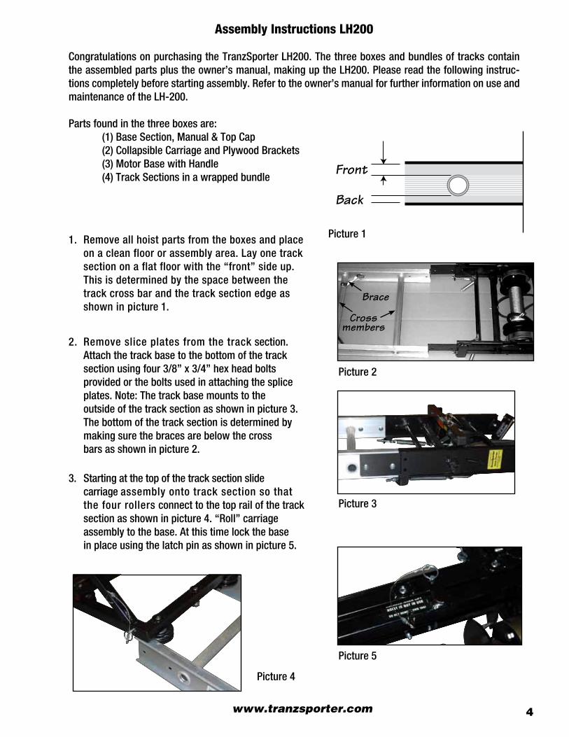
Assembly Instructions LH200
CongratulationsonpurchasingtheTranzSporterLH200.Thethreeboxesandbundlesoftrackscontaintheassembledpartsplustheowner’smanual,makinguptheLH200.Pleasereadthefollowinginstruc-tionscompletelybeforestartingassembly.Refertotheowner’smanualforfurtherinformationonuseandmaintenanceoftheLH-200.
Partsfoundinthethreeboxesare: (1)BaseSection,Manual&TopCap (2)CollapsibleCarriageandPlywoodBrackets (3)MotorBasewithHandle (4)TrackSectionsinawrappedbundle
1. Removeallhoistpartsfromtheboxesandplace onacleanfloororassemblyarea.Layonetrack sectiononaflatfloorwiththe“front”sideup. Thisisdeterminedbythespacebetweenthe trackcrossbarandthetracksectionedgeas showninpicture1.
2. Removesliceplatesfromthetracksection. Attachthetrackbasetothebottomofthetrack sectionusingfour3/8”x3/4”hexheadbolts providedortheboltsusedinattachingthesplice plates.Note:Thetrackbasemountstothe outsideofthetracksectionasshowninpicture3. Thebottomofthetracksectionisdeterminedby makingsurethebracesarebelowthecross barsasshowninpicture2.
3. Startingatthetopofthetracksectionslide carriage assemblyontotracksectionsothat thefourrollersconnecttothetoprailofthetrack sectionasshowninpicture4.“Roll”carriage assemblytothebase.Atthistimelockthebase inplaceusingthelatchpinasshowninpicture5.
Picture1
Picture2
Picture3
Picture5
Picture4
Brace
Crossmembers
Front
Back
Tie Down Engineering • 255 Villanova Dr. SW • Atlanta, Georgia 303365
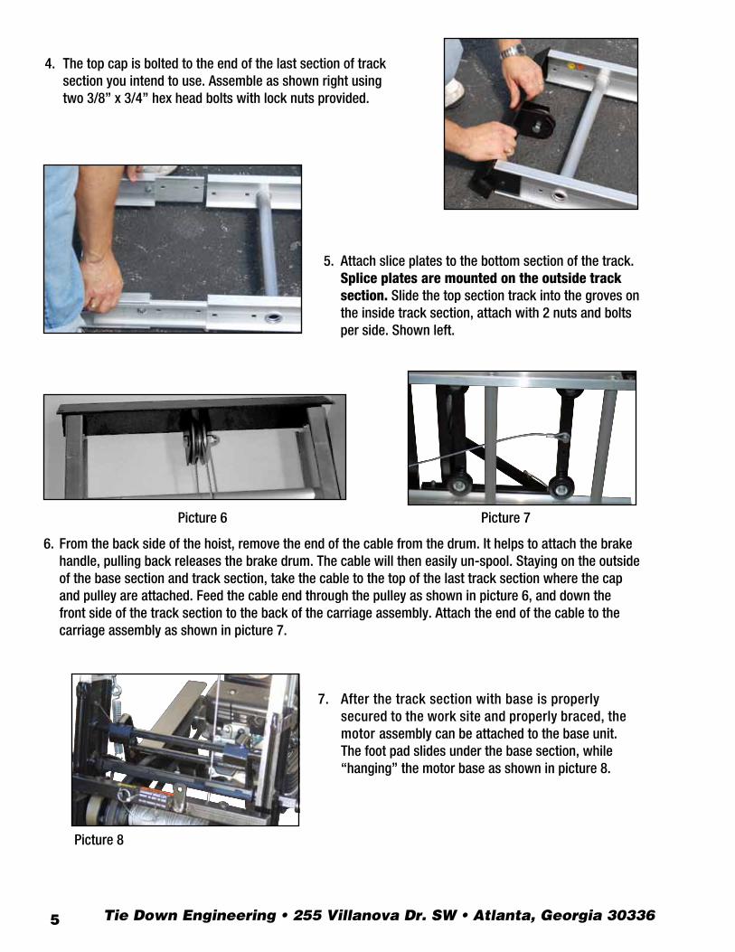
4. Thetopcapisboltedtotheendofthelastsectionoftrack sectionyouintendtouse.Assembleasshownrightusing two3/8”x3/4”hexheadboltswithlocknutsprovided.
7. Afterthetracksectionwithbaseisproperly securedtotheworksiteandproperlybraced,the motorassemblycanbeattachedtothebaseunit. Thefootpadslidesunderthebasesection,while “hanging”themotorbaseasshowninpicture8.
Picture7
Picture8
5. Attachsliceplatestothebottomsectionofthetrack. Splice plates are mounted on the outside track section.Slidethetopsectiontrackintothegroveson theinsidetracksection,attachwith2nutsandbolts perside.Shownleft.
6. Fromthebacksideofthehoist,removetheendofthecablefromthedrum.Ithelpstoattachthebrake handle,pullingbackreleasesthebrakedrum.Thecablewilltheneasilyun-spool.Stayingontheoutside ofthebasesectionandtracksection,takethecabletothetopofthelasttracksectionwherethecap andpulleyareattached.Feedthecableendthroughthepulleyasshowninpicture6,anddownthe frontsideofthetracksectiontothebackofthecarriageassembly.Attachtheendofthecabletothe carriageassemblyasshowninpicture7.
Picture6
(404) 344-0000 • Fax (404) 349-0401 • www.tranzsporter.com 6
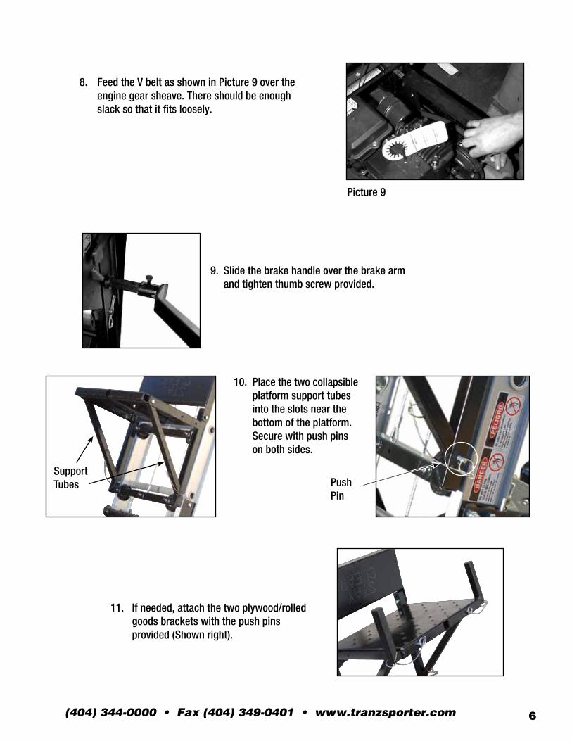
9. Slidethebrakehandleoverthebrakearm andtightenthumbscrewprovided.
Picture9
11. Ifneeded,attachthetwoplywood/rolled goodsbracketswiththepushpins provided(Shownright).
10. Placethetwocollapsible platformsupporttubes intotheslotsnearthe bottomoftheplatform. Securewithpushpins onbothsides.
SupportTubes Push
Pin
8. FeedtheVbeltasshowninPicture9overthe enginegearsheave.Thereshouldbeenough slacksothatitfitsloosely.
Tie Down Engineering • 255 Villanova Dr. SW • Atlanta, Georgia 303367
Raising the Track Section Assembly
WARNING: KEEP TRACK SECTIONS CLEAR OF ALL ELECTRICAL WIRES AND EQUIPMENTBE AWARE OF OVERHEAD OBJECTS-NEVER CLIMB HOIST!Thehoistassemblyisextremelytopheavyandmustbekeptundercontrolatalltimes.Twoalternatemethodsaresuggestedforraisingtheplatformhoisttotheoperatingposition.
PROCEDURE “A” Thisprocedurerequirestwoorpreferablythreemen.1.Laytheassembledtracksectionswiththeplatformattachedparalleltothebuildingwallthatistosupportthehoist.2.Tiearopetotheheadbracketandhavethemanonroofpullupthehoistwhiletheothermanonthegroundbracestheshoesonthebottomsectiontopreventslippageofthehoistshoes.Thethirdmanonthegroundmayaidinerectingby“walking”thehoistuphandoverhandbytherungs.3.Whenthehoistreachesaverticalposition,carefullyturnthehoist90degreeswiththeplatformpointingawayfromthebuilding.Movethebottomofthehoistawayfromthebuilding,1/4oftheheightofthebuildingwherethetopofthehoististobesupported.Makeallowancesforoverhang.Seetracksectionsupportchartforapproximatedistancesofthebasefromthebottomtrack.
ALTERNATE PROCEDURE “B”1.Placetracksectionassemblyperpendiculartothebuildingwiththebottomshoesofthesteelbottomsectionrestingagainstthebuildingtopreventslipping.2.Tiearopetotheheadbracketandhavethemanontheroofpullupthehoistwhiletheothermanonthegroundbracestheshoesonthesteelbottomsectiontopreventslippageofthehoistshoes.Thethirdmanonthegroundmayaidinerectingby“walking”thehoistuphandoverhandbytherungs.
GASOLINE POWER UNIT1. Handlefuelwithcare.ItisEXTREMELYflammableandexplosiveundercertainconditions.2. Donotsmoke,allowopenflamesorsparkstobepresentduringtherefuelingoperation.3. Useonlyanapprovedfuelcontainertotransportfuel.4. Donotfuelwhileengineishot-allowtocoolbeforeattemptingtherefuelingoperation.5. Replaceallfueltankcapssecurelyandwipethespilledfuelbeforerestartingengine.6. DonotoperatetheLH-Seriesgasolineengineinanenclosedarea.Theexhaustcanbeespecially hazardousinanenclosedarea.7. Stoptheengineandlowertheplatformwhenleavingthevicinityofthehoist.8. Alwaysstoptheengine,lowertheplatform,waitforallmovingpartstostop,andallowtheengine tocoolbeforedisassemblingormovingthehoist.9. Disconnectthesparkplugwirefromtheplugbeforedisassemblingormovingthehoist.10. DONOTstoretheengineinanenclosedarea.11. Allowenginetocoolbeforestoring.12. DONOTstoreenginewhereitmightbesubjectedtoflames,sparks,extremeheatoranyother sourceofcombustion.
(404) 344-0000 • Fax (404) 349-0401 • www.tranzsporter.com 8
WARNING: BEFORE LOWERING THE TRACK SECTIONS, CAREFULLY CHECK FOROVERHEAD OBJECTS AND POWER LINES.
Raising the platform with or without loadWARNING: THE OPERATOR OF THIS HOIST UNIT SHOULD WEAR APPROPRIATE SAFETY EQUIPMENT WHICH SHOULD INCLUDE APPROVED HAND PROTECTION, HEAD PROTECTION AND EYE PROTECTION.
ToraisetheplatformonLH200,facetheplatformandstandasfaraspossiblefromthehoisttooperate.Placeyourfootonthefootcontrolbracetoengagethemotortodrumbelt,permittingtheplatformtorollupthetracksection.Whentheplatformreachesthetop,releasefootIMMEDIATELY.Thiswillapplytheselfenergizingbrake.Moveawayfromthehoistwhiletheloadisbeingremovedfromtheplatform.
Lowering the platformTolowerthecarriage,standtotherightorleftsideofthehoistandgraspthebrakehandle.Lightlyfeathertheplatformdownbyengaginganddisengagingthebraketoslowthecarriage.Lowerthecarriagetothegroundataslowspeed(nottoexceed50/feetperminute).Continuetodeceleratetheplatformasitnearsthegroundtopreventdamagetotheplatformorbottombracestops.DO NOT USE THE HOIST TO LOWER MATERIALS.
CAUTION: NEVER APPLY THE BRAKE ABRUPTLY - BROKEN HOIST CABLES AND/OR SEVERE INJURY TO PERSONNEL OR EQUIPMENT MAY OCCUR. MAKE CERTAIN PLATFORM DOES NOT STRIKE THE BOTTOM BRACE STOPS UPON REACHING THE BOTTOM OF THE TRACK SECTION.
Loweranddismantletheplatformhoistassemblyinthereverseoftheerectionprocedure,observingallsafetyprocedures.
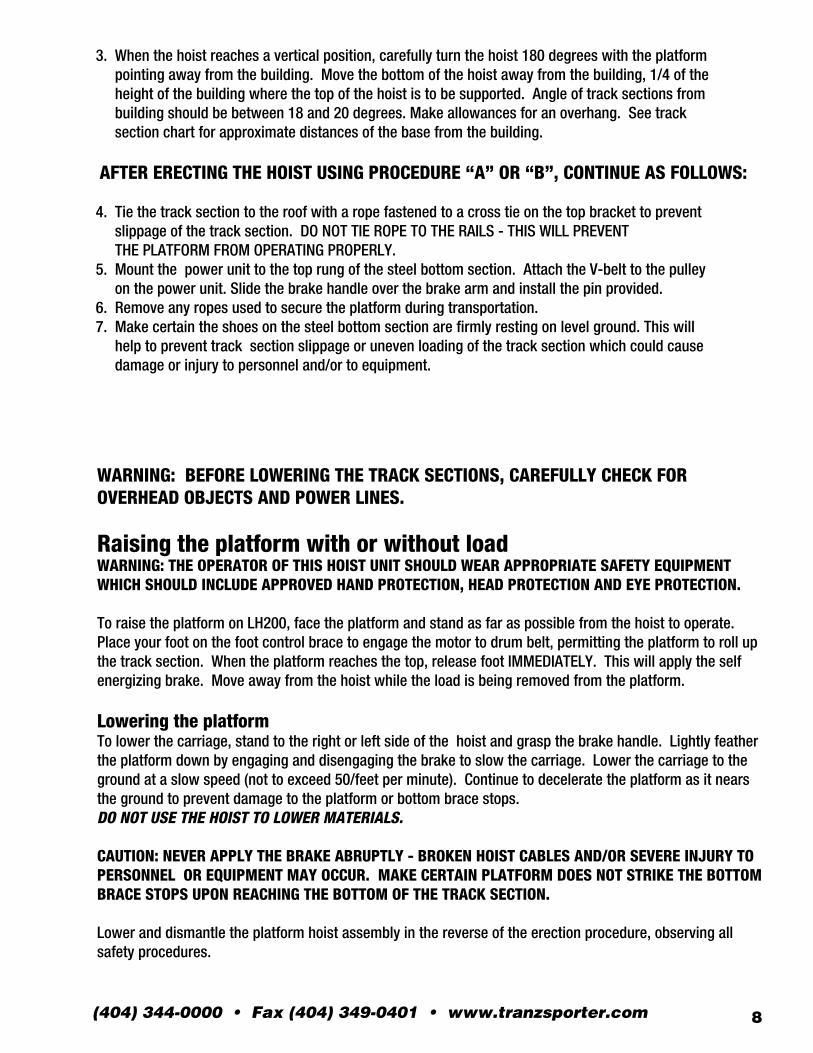
3.Whenthehoistreachesaverticalposition,carefullyturnthehoist180degreeswiththeplatformpointingawayfromthebuilding.Movethebottomofthehoistawayfromthebuilding,1/4oftheheightofthebuildingwherethetopofthehoististobesupported.Angleoftracksectionsfrombuildingshouldbebetween18and20degrees.Makeallowancesforanoverhang.Seetracksectionchartforapproximatedistancesofthebasefromthebuilding.
AFTER ERECTING THE HOIST USING PROCEDURE “A” OR “B”, CONTINUE AS FOLLOWS:
4.Tiethetracksectiontotheroofwitharopefastenedtoacrosstieonthetopbrackettopreventslippageofthetracksection.DONOTTIEROPETOTHERAILS-THISWILLPREVENTTHEPLATFORMFROMOPERATINGPROPERLY.5.Mountthepowerunittothetoprungofthesteelbottomsection.AttachtheV-belttothepulleyonthepowerunit.Slidethebrakehandleoverthebrakearmandinstallthepinprovided.6.Removeanyropesusedtosecuretheplatformduringtransportation.7.Makecertaintheshoesonthesteelbottomsectionarefirmlyrestingonlevelground.Thiswillhelptopreventtracksectionslippageorunevenloadingofthetracksectionwhichcouldcausedamageorinjurytopersonneland/ortoequipment.
Tie Down Engineering • 5901 Wheaton Drive • Altanta, Georgia 303369
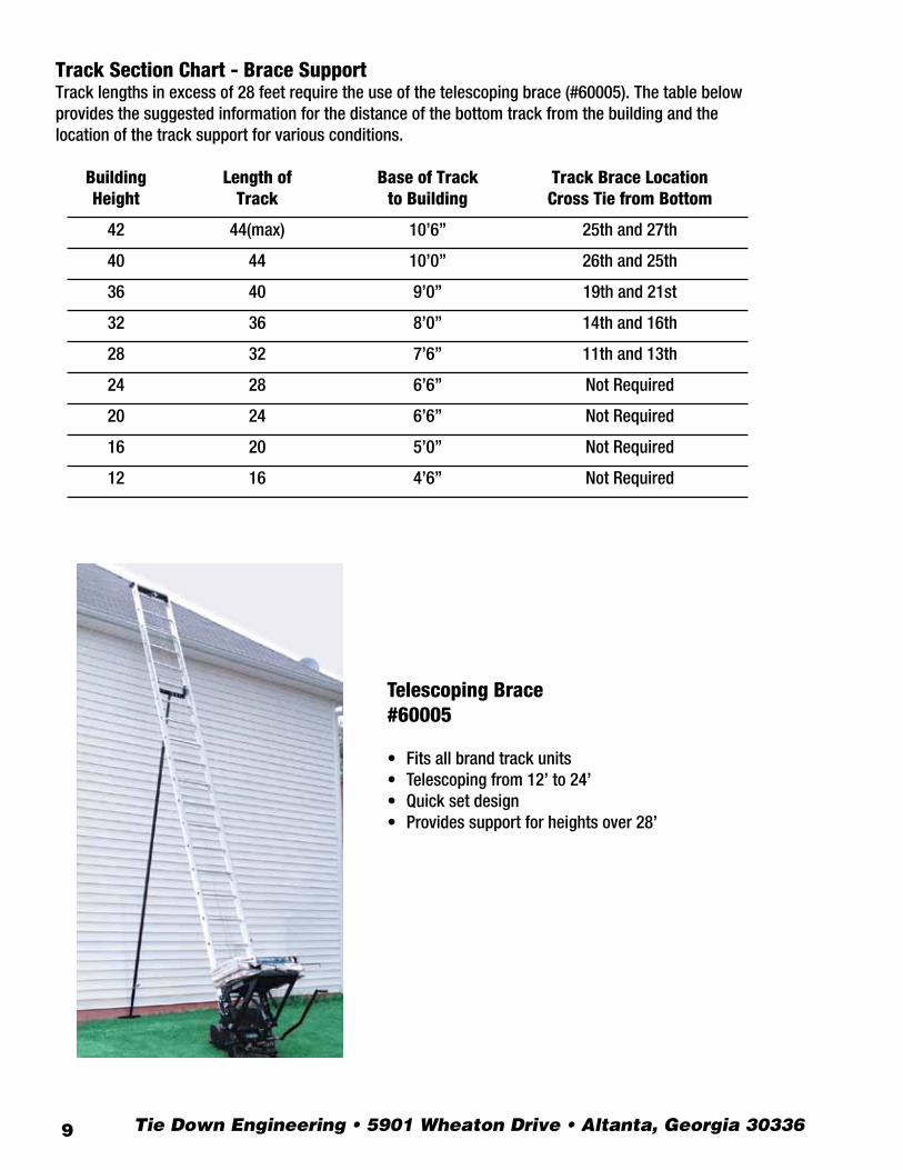
Telescoping Brace#60005
• Fitsallbrandtrackunits• Telescopingfrom12’to24’• Quicksetdesign• Providessupportforheightsover28’
Track Section Chart - Brace SupportTracklengthsinexcessof28feetrequiretheuseofthetelescopingbrace(#60005).Thetablebelowprovidesthesuggestedinformationforthedistanceofthebottomtrackfromthebuildingandthelocationofthetracksupportforvariousconditions.
Building Length of Base of Track Track Brace Location Height Track to Building Cross Tie from Bottom
42 44(max) 10’6” 25thand27th
40 44 10’0” 26thand25th
36 40 9’0” 19thand21st
32 36 8’0” 14thand16th
28 32 7’6” 11thand13th
24 28 6’6” NotRequired
20 24 6’6” NotRequired
16 20 5’0” NotRequired
12 16 4’6” NotRequired
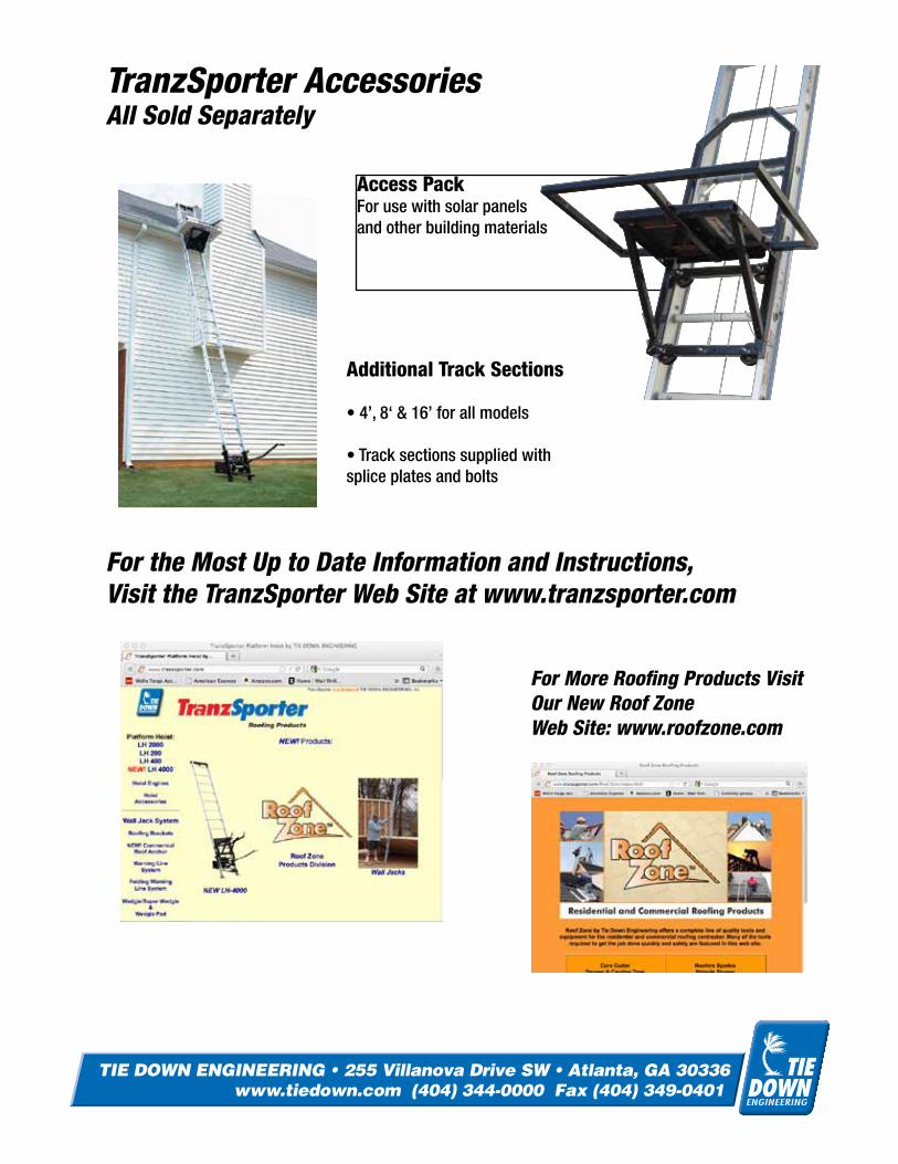
Access PackForusewithsolarpanelsandotherbuildingmaterials
TranzSporter AccessoriesAll Sold Separately
For the Most Up to Date Information and Instructions,Visit the TranzSporter Web Site at www.tranzsporter.com
For More Roofing Products Visit Our New Roof ZoneWeb Site: www.roofzone.com
Additional Track Sections
•4’,8‘&16’forallmodels
•Tracksectionssuppliedwithspliceplatesandbolts
4 color
TIE DOWN ENGINEERING • 255 Villanova Drive SW • Atlanta, GA 30336www.tiedown.com (404) 344-0000 Fax (404) 349-0401
TIE DOWN ENGINEERING • 255 Villanova Drive SW • Atlanta, GA 30336www.tiedown.com (404) 344-0000 Fax (404) 349-0401
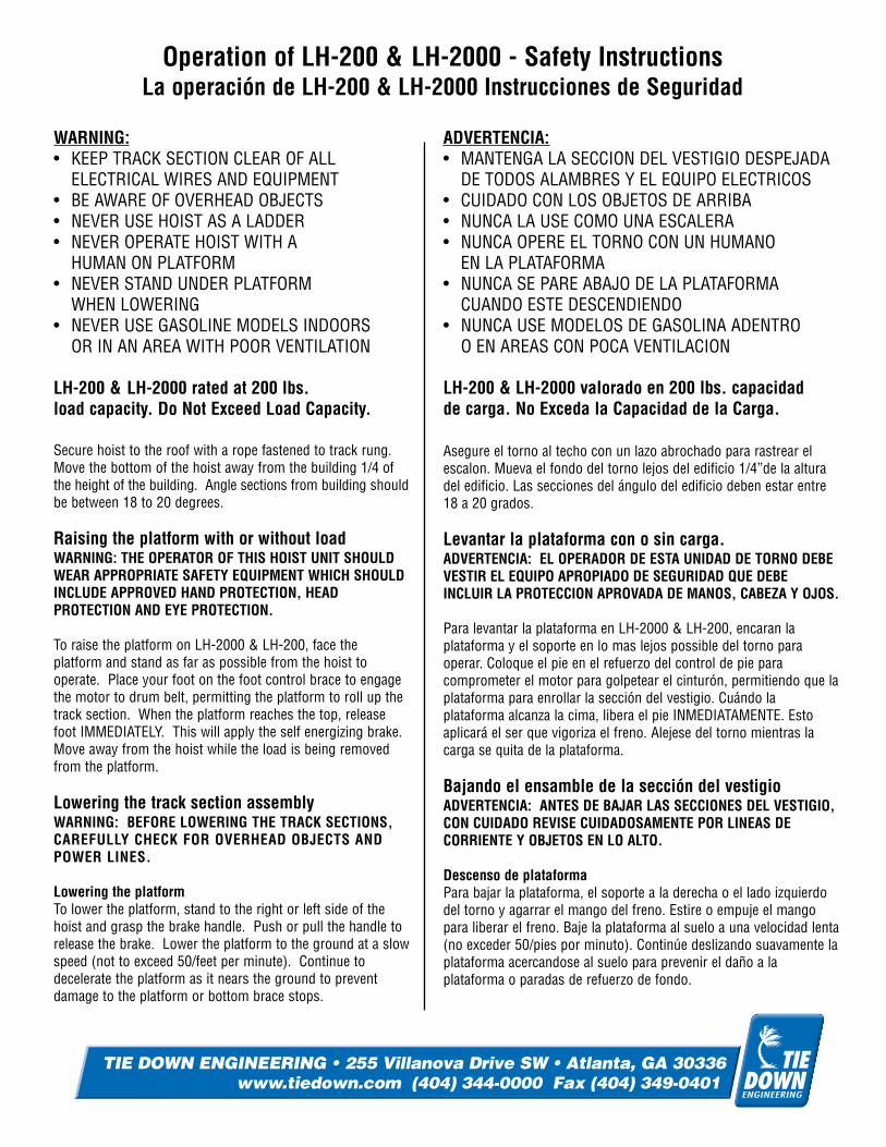
Operation of LH-200 & LH-2000 - Safety InstructionsLa operación de LH-200 & LH-2000 Instrucciones de Seguridad
WARNING:• KEEP TRACK SECTION CLEAR OF ALL
ELECTRICAL WIRES AND EQUIPMENT• BE AWARE OF OVERHEAD OBJECTS• NEVER USE HOIST AS A LADDER• NEVER OPERATE HOIST WITH A
HUMAN ON PLATFORM • NEVER STAND UNDER PLATFORM
WHEN LOWERING• NEVER USE GASOLINE MODELS INDOORS
OR IN AN AREA WITH POOR VENTILATION
ADVERTENCIA:• MANTENGA LA SECCION DEL VESTIGIO DESPEJADA
DE TODOS ALAMBRES Y EL EQUIPO ELECTRICOS • CUIDADO CON LOS OBJETOS DE ARRIBA • NUNCA LA USE COMO UNA ESCALERA • NUNCA OPERE EL TORNO CON UN HUMANO
EN LA PLATAFORMA• NUNCA SE PARE ABAJO DE LA PLATAFORMA
CUANDO ESTE DESCENDIENDO • NUNCA USE MODELOS DE GASOLINA ADENTRO
O EN AREAS CON POCA VENTILACION
LH-200 & LH-2000 rated at 200 lbs.load capacity. Do Not Exceed Load Capacity.
LH-200 & LH-2000 valorado en 200 lbs. capacidadde carga. No Exceda la Capacidad de la Carga.
Secure hoist to the roof with a rope fastened to track rung.Move the bottom of the hoist away from the building 1/4 ofthe height of the building. Angle sections from building shouldbe between 18 to 20 degrees.
Raising the platform with or without loadWARNING: THE OPERATOR OF THIS HOIST UNIT SHOULDWEAR APPROPRIATE SAFETY EQUIPMENT WHICH SHOULDINCLUDE APPROVED HAND PROTECTION, HEADPROTECTION AND EYE PROTECTION.
To raise the platform on LH-2000 & LH-200, face theplatform and stand as far as possible from the hoist tooperate. Place your foot on the foot control brace to engagethe motor to drum belt, permitting the platform to roll up thetrack section. When the platform reaches the top, releasefoot IMMEDIATELY. This will apply the self energizing brake.Move away from the hoist while the load is being removedfrom the platform.
Lowering the track section assemblyWARNING: BEFORE LOWERING THE TRACK SECTIONS,CAREFULLY CHECK FOR OVERHEAD OBJECTS ANDPOWER LINES.
Lowering the platformTo lower the platform, stand to the right or left side of thehoist and grasp the brake handle. Push or pull the handle torelease the brake. Lower the platform to the ground at a slowspeed (not to exceed 50/feet per minute). Continue todecelerate the platform as it nears the ground to preventdamage to the platform or bottom brace stops.
Asegure el torno al techo con un lazo abrochado para rastrear elescalon. Mueva el fondo del torno lejos del edificio 1/4”de la alturadel edificio. Las secciones del ángulo del edificio deben estar entre18 a 20 grados.
Levantar la plataforma con o sin carga.ADVERTENCIA: EL OPERADOR DE ESTA UNIDAD DE TORNO DEBEVESTIR EL EQUIPO APROPIADO DE SEGURIDAD QUE DEBEINCLUIR LA PROTECCION APROVADA DE MANOS, CABEZA Y OJOS.
Para levantar la plataforma en LH-2000 & LH-200, encaran laplataforma y el soporte en lo mas lejos possible del torno paraoperar. Coloque el pie en el refuerzo del control de pie paracomprometer el motor para golpetear el cinturón, permitiendo que laplataforma para enrollar la sección del vestigio. Cuándo laplataforma alcanza la cima, libera el pie INMEDIATAMENTE. Estoaplicará el ser que vigoriza el freno. Alejese del torno mientras lacarga se quita de la plataforma.
Bajando el ensamble de la sección del vestigio ADVERTENCIA: ANTES DE BAJAR LAS SECCIONES DEL VESTIGIO,CON CUIDADO REVISE CUIDADOSAMENTE POR LINEAS DECORRIENTE Y OBJETOS EN LO ALTO.
Descenso de plataformaPara bajar la plataforma, el soporte a la derecha o el lado izquierdodel torno y agarrar el mango del freno. Estire o empuje el mangopara liberar el freno. Baje la plataforma al suelo a una velocidad lenta(no exceder 50/pies por minuto). Continúe deslizando suavamente laplataforma acercandose al suelo para prevenir el daño a laplataforma o paradas de refuerzo de fondo.
4 color
TIE DOWN ENGINEERING • 255 Villanova Drive SW • Atlanta, GA 30336www.tiedown.com (404) 344-0000 Fax (404) 349-0401
TIE DOWN ENGINEERING • 255 Villanova Drive SW • Atlanta, GA 30336www.tiedown.com (404) 344-0000 Fax (404) 349-0401


![[XLS] · Web viewHOIST HOIST EQUIPMENT ACTUATOR, MLG HOIST HOIST EQUIPMENT - ACTUATOR, MLG HOIST HOIST - CARDAN PIN HOIST HOIST-CARDAN PIN HOIST HOIST-DEVICE,FLAP TRACK 2-5 HOIST](https://img.pdfslide.net/doc/110x75/5b1fa5177f8b9aa64c8b4800/xls-web-viewhoist-hoist-equipment-actuator-mlg-hoist-hoist-equipment-actuator.jpg)