Embed Size (px)
Citation preview

Cable Systems, Cables and Accessories
Plug-in TerminaTions for XlPe-insulaTed 12 – 52 kV medium VolTage Cables
aCCessories

siliCone rubber – righT from The sTarT
Südkabel has set many milestones with its cable accessories for energy transmission. The company has done pioneering work, particularly in the field of silicone rubber technology. The first one-piece medium voltage accessories were already being used back in the seventies. The company is therefore the trailblazer of a technology that did not take long to become a standard for medium voltage accessories and that is used today in accessories for up to 550 kV.
The properties of silicone rubber make it the ideal material for cable accessories:
• Gooddielectricproperties• Highdegreeofelasticity(forperfectadaptiontostrippedcableinsulations)• OzoneandUVresistance• Long-termhydrophobicity• Highleakagecurrentandarcresistance• Usableinawiderangeoftemperatures• Carbon-freematerial
AtSüdkabel,differenttypesofsiliconerubberareused.Ontheonehand,this enables the cost-efficient production of standard accessories on a largescale.Ontheotherhand,smallbatchescanalsobemanufacturedat a reasonable expense.
The Südkabel standard range of medium voltage accessories includes:
• Multi-rangeterminationsforindoorandoutdoorapplications• Multi-rangestraight-throughandtransitionjoints• Plug-typeconnectors(cableplugs)formetal-enclosedswitchgears
with inner or outer cone
All accessories are type tested to the DIN VDE 0278-629-1 revision valid at the time of market launch.
2

ConTenTs
Plug-in terminations (cable plugs) for metal-enclosed switchgears
Since their introduction to the market in the 1980s, metal-enclosed SF6-insulated medium voltage switchgears have become increasingly important due to their undisputed benefits. Amongst others, the compact design enabled by this technology lead to reduction of phase spacings which meant, however, that traditional terminations in an uninsulated connection technique used up until then could no longer be allowed. Otheradvantagessuchasshock-proofconditions,independencefromambient conditions and no maintenance requirements could no longer be realised with these terminations. It was therefore necessary to develop a new generation of terminations: metal-enclosed cable terminations.
Unlikeconventionalterminations,theswitchgearinterfaceofmetal-enclosed terminations has to be defined more precisely. In this case, it consists of cone-shaped bushings according to the European standards DIN EN 50180 “Bushings above 1 kV to 36 kV and 250 A to 3150 A for liquid-immersedtransformers”andDINEN50181“Plug-inbushingsabove 1 kV to 36 kV and 250 A to 1.25 kA for equipment other than liquid-immersed transformers”.
Today, two systems with different application areas are established: a system with inner cone and a system with outer cone.
Welcome to Südkabel 2
Outer cone system 5 - 15
Bushings 5
Cableplug-interminations 6
Bushing type A 6
Bushing type B 7
BushingtypeC 8
Accessories 12
Inner cone system 16 - 17
Bushings 16
Cableplug-interminations 17
Accessories 18 - 19
Our offer 20
3

TesTing Values
Testing to DIN VDE 0278-629-1(TestingmethodsaccordingtoDINVDE0278-628)
EN 61442Section
Test values for rated voltage Results
U0/UUm
6/1012
12/2024
18/3036
26/4552 *
kV kV
DCwithstandvoltage15min 5 kV 36 72 108 156 no breakdown or flashover
ACwithstandvoltage5min 4 kV 27 54 81 117 no breakdown or flashover
Partialdischargeatambienttemperature 7 kV 12 24 36 45 max.10pCatXLPE/EPRcables
Impulse at elevated temperature(10impulseswithpos.andneg.polarity)
6 kV 75 125 170 250 no breakdown or flashover
Loadcyclesinair(63cycles)9 kV 15 30 45 65
no breakdown or flashoverTemperature acc. to DIN VDE 0278-628 section 9
Loadcyclesunderwater(63cycles) 9 kV 15 30 45 65 no breakdown or flashover
Partialdischargeatambientandelevated temperature
7 kV 12 24 36 45 max.10pCatXLPE/EPRcables
Thermalshortcircuit(screen) 10 2 short circuits ISC
Thermalshortcircuit(conductor) 112 short circuits to increase the conductor temperature
Dynamic short circuit 12 to be agreed upon
Disconnect/Connect 5 times no visible damage at the contact element
Partialdischargeatambientandelevated temperature
7 kV 12 24 36 45 max.10pCatXLPE/EPRcables
Impulse at elevated temperature(10impulseswithpos.andneg.polarity)
6 kV 75 120 170 250 no breakdown or flashover
ACwithstandvoltage15min 4 kV 15 30 45 65 no breakdown or flashover
Operatingeye 19Axial force: 1.3 kN for 1 minTorque: 14 Nm
Partialdischargeatambienttemperature 7 kV 12 24 36 45 max.10pCatXLPE/EPRcables
Screen resistance 17max5,000Ohmmax0.5mAatUm
Fault current ignition 18
Faultignitionmustoccurwithin3s(solidlyearthedsystem);faultcurrenttoflowcon-tinuously(unearthed/impedanceearthedsystem)
Operatingforce Force less than 900 Nm
Capacitivetestpointperformance CTC<1pF,CTC/CTE < 12
Allplug-interminationsaretypetestedtotheDINVDE0278-629-1revisionvalidatthetimeofmarketlaunch.Pleaserefertothefollowingtable for the current test values.
* According to DIN VDE 0278-629-1
4

ouTer Cone sysTembushings
As a result of the different models of bushings and the varying field requirements, different versions of plug-in terminations with outer cones are available. Südkabel offers plug-in terminations that are elbow-shaped, straight or T-shaped. In many cases, the insulation bodies made of silicone rubber are multi-ranged and can be combined with hexagonal compression cable lugs or with mechanical cable lugs with shear-off bolts. A conductive coating makes these plug-in terminations independent of ambient conditions, maintenance-free and submersible.
All plug-in terminations are available with an additional metal housing for electric shock protection.
The standards EN 50180 and EN 50181 define six types of bushings for the outer cone system up to 36 kV, of which only 3 are relevant in practice:
Bushing type A (Rated current 250 A)
• BushingtypeAwitharatedcurrentof 250 A are suitable for a maximum operating voltage of 24 kV.
• Thecontactelementisdimensionedforcontact pins of 7.9 mm in diameter.
• Theyaregenerallyusedondistributiontransformers,motorjunctionboxesandattransformer feeders of switch disconnector substations up to 24 kV in distributor sta-tions for local networks.
For these bushings, elbow-shaped and straight plug-in terminations are available (e.g.SEW24andSEHDG21.1).
Bushing type B (Rated current 250 – 400 A)
• BushingtypeBwitharatedcurrentof250 to 400 A are suitable for a maximum operating voltage of 36 kV.
• Thecontactelementisdimensionedforcontact pins of 14 mm in diameter.
• Theyaregenerallyusedondistributiontransformers,motorjunctionboxesandontransformer feeders of switch disconnector substations up to 36 kV in distributor sta-tions for local networks.
For these bushings, T-shaped and straight plug-in terminations are available (e.g.SET24-BandSEHDG22).
Bushing type C (Rated current 630 – 1250 A)
• BushingtypeCwitharatedcurrentof 630 to 1250 A are appropriate for a maximum operating voltage of 36 kV.
• ThecontactelementisdimensionedforM16x2threadedpins.
• Theyaregenerallyusedonring-mainsystems of substations in local networks but also in switch disconnector substations of transformer stations.
For these bushings, T-shaped and straight plug-in terminations are available (e.g.SETandSEHDG23).
All values in mm
Rated current Maximumoperatingvoltage Designation Contactelement
250 A 24 kV Interface type A Contactpin Ø 7.9 mm
250 – 400 A 36 kV Interface type B Contactpin Ø14mm
630 – 1250 A 36 kV InterfacetypeC M16threadedpin
5

Elbow plug-in terminations SEW and SEHDW, Um up to 24 kV
• Conductorandscreenconnectionforcompressionand mechanicalconnections(shear-offbolts).
• Availablewithconductivecoatingonly.• Optionallywithadditionalmetalhousing.• Coveroffivecablecross-sectionswithoneinsulating
bodysizeandastresscontrollingadapter(SEW).• Fixationwithtwoextensionsprings(SEW)oronefixingring
and hooks.
Elbow and straight plug-in terminations of type A are suitable for bushings according to DIN EN 50180 and DIN EN 50181, interface type A, rated current 250 A.
Straight plug-in termination SEHDG, Um up to 24 kV
• Conductorandscreenconnectionforcompressionand mechanicalconnections(shear-offbolts).
• Availablewithconductivecoatingonly.• Optionallywithadditionalmetalhousing.• Eachcross-sectionisassignedaninsulatingbodysize.• Fixationwithfixingringandhooks.
1) Forcablesacc.toDINVDE0276-620(crosssectionsinbracketsareonlypartlycovered)2) Withstresscontrollingadapter
3) Eachcrosssectionisassignedaseparateinsulatingbody4) Datawithout/withmetalhousing
aCCessories for ouTer Cone sysTems inTerfaCe TyPe a
1 Bushing with outer cone
2 Insulating body
3 Connectionboltwithcontactpin
4 Stress controlling electrode
5 Conductivecoating
6 Earthing connections
7 Sealing and insulating wrap
8 Earthing clamp
9 Fixing elements
VoltageUm
kV
Type Admissible outer diameter
mm
Conductorcrosssectionofthe insulating body 1)
mm²
MeasureD
mm
MeasureL1
mm
MeasureL2
mm
12 SEW12 12.2 – 18.6 2) 25–70(95) 58/74 4) 105/108 4) 245/245 4)
12 SEW12 17.3 – 25.0 (70)95–150 58/74 4) 105/108 4) 245/245 4)
12 SEHDG11.1 12.7 – 24.3 3) 25 – 150 58/68 4) - 275/285 4)
24 SEW24 17.3 – 25.0 2) (25)35–95 58/74 4) 105/108 4) 245/245 4)
24 SEHDW21 22.5 – 28.5 3) (95)120–150 64/74 4) 118/134 4) 235/265 4)
24 SEHDG21.1 17.0 – 24.3 3) 25 – 70 58/68 4) - 275/285 4)
24 SEHDG21 22.5 – 28.5 3) 95 – 150 71/92 4) - 280/310 4)
6

aCCessories for ouTer Cone sysTems inTerfaCe TyPe b
T-shaped plug-in terminations SET-B, Um up to 36 kV
• Conductorandscreenconnectionforcompressionand mechanicalconnections(shear-offbolts).
• Availablewithconductivecoatingonly.• Optionallywithadditionalmetalhousing.• Coveruptoeightcablecross-sectionswithoneinsulating
body size and a stress controlling adapter.• Fixationwithonefixingringandtwoextensionspringsor
alternatively with fixing ring and claws.• Capacitivevoltagetap.
Straight plug-in termination SEHDG, Um up to 24 kV
• Conductorconnectionforaspecialclampingboltsuitable forAlandCuconductors.
• Availablewithconductivecoatingonly.• Optionallywithadditionalmetalenclosure.• Eachcross-sectionisassignedaninsulatingbodysize.• Fixationwithfixingringandclaws.
1 Bushing with outer cone
2 Insulating body
3 Castresinterminatingelement
4 Connectionboltwithcontactpin
5 Stress controlling electrode
6 Conductivecoating
7 Earthing connections
8 Sealing wrap
9 Earthing clamp
10 Earthing cap
11 Fixing elements
12 Braided copper tape
13 Heatshrinkabletube
1) Forcablesacc.toDINVDE0276-6202) Withstresscontrollingadapter3) Datawithout/withmetalhousing
4) Datawithout/withmetalhousingonrequest5) Eachcrosssectionisassignedaseparateinsulatingbody6) Datawith/withoutmetalhousing,metalhousingisflattenedonthesidefor85mmphasespacing
T-shaped and straight plug-in terminations of type B are suitable for bushings according to DIN EN 50180 and DIN EN 50181, interface type B, rated current 250/400 A.
VoltageUm
kV
Type Admissible outer diameter
mm
Conductorcrosssectionoftheinsulating body 1)
mm²
MeasureD1
mm
MeasureD2
mm
MeasureL1
mm
MeasureL2
mm
12 SET 12-B 2) 15.0 – 23.5 50 – 150 74/88 3) 53/71 3) 188/188 3) 275/275 3)
12 SET 12-B 21.8 – 32.6 185 – 300 74/88 3) 53/71 3) 188/188 3) 275/275 3)
12 SEHDG12 13.7 – 28.4 5) 50 – 240 79/896) - - 317/347 6)
24 SET 24-B 2) 15.0 – 23.5 25 – 70 74/88 3) 53/71 3) 188/188 3) 275/275 3)
24 SET 24-B 21.8 – 32.6 95 – 240 74/88 3) 53/71 3) 188/188 3) 275/275 3)
24 SEHDG22 15.0 – 32.6 5) 25 – 240 79/89 6) - - 317/347 6)
36 SET 36-B 26.2 – 32.0 70 – 120 74/- 4) 85/- 4) 188/- 4) 290/- 4)
36 SET 36-B 30.8 – 39.6 150 – 300 74/- 4) 85/- 4) 188/- 4) 290/- 4)
7

aCCessories for ouTer Cone sysTems inTerfaCe TyPe C
TheT-shapedterminationoftypeCissuitablefor bushings according to DIN EN 50180 and DIN EN 50181, interfacetypeC,ratedcurrent630/1250A.
T-shaped plug-in terminations SET and SAT, Um up to 36 (42) kV / coupling termination SEHDK, Um up to 36 (42) kV
• Conductorandscreenconnectionforcompression andmechanicalconnections(shear-offbolts).
• Availablewithconductivecoatingonly.• Optionallywithadditionalmetalhousing.
• Coveruptoeightcablecross-sectionswithone insulating body size and a stress controlling adapter.
• Capacitivevoltagetap.
ThecouplingterminationSEHDKcanbeusedtoexpanda T-shaped termination connected to the system to a space-saving and convenient parallel connection without a coupling element.
1 Bushing with outer cone
2 Insulating body
3 Castresinterminatingelement
4 Connectionboltwiththreadedpin
5 Stress controlling electrode
6 Conductivecoating
7 Earthing connections
8 Sealing wrap
9 Earthing clamp
10 Earthing cap
11 Copperbolt
12 InsulatingbodySEHDK
13 Insulating body SET
1) Forcablesacc.toDINVDE0276-6202) Withstresscontrollingadapter
3) Datawithout/withmetalhousing4) Datawithout/withmetalhousingonrequest5) Eachcrosssectionisassignedaseparateinsulatingbody
VoltageUm
kV
Type Admissible outer diameter
mm
Conductorcrosssectionoftheinsulating body 1)
mm²
MeasureD1
mm
MeasureD2
mm
MeasureL1
mm
MeasureL2
mm
12 SET 12 2) 15.0 – 23.5 50 – 150 74/88 3) 53/71 3) 188/188 3) 275/275 3)
12 SET 12 21.8 – 32.6 185 – 300 74/88 3) 53/71 3) 188/188 3) 275/275 3)
12 SEHDK13.12) 15.0 – 23.5 50 – 150 77/- 4) 53/- 4) 290/- 4) 275/- 4)
12 SEHDK13.1 21.8 – 32.6 185 – 300 77/- 4) 53/- 4) 290/- 4) 275/- 4)
24 SET 24 2) 15.0 – 23.5 25 – 70 74/88 3) 53/71 3) 188/188 3) 275/275 3)
24 SET 24 21.8 – 32.6 95 – 240 74/88 3) 53/71 3) 188/188 3) 275/275 3)
24 SEHDT23.1 31.6 – 34.6 300 74/88 3) 53/71 3) 188/188 3) 275/275 3)
24 SEHDK23.12) 15.0 – 23.5 25 – 70 77/- 4) 53/- 4) 290/- 4) 275/- 4)
24 SEHDK23.1 21.8 – 32.6 95 – 240 77/- 4) 53/- 4) 290/- 4) 275/- 4)
36(42) SET36(42) 26.2 – 32.0 70 – 120 74/- 4) 73/- 4) 196/- 4) 290/- 4)
36(42) SET36(42) 30.8 – 39.6 150 – 300 74/- 4) 73/- 4) 196/- 4) 290/- 4)
36(42) SAT 36 35.0 – 59.4 5) 300 – 1000 110/- 4) 88/- 4) 209/- 4) 425/- 4)
36(42) SEHDK36(42) 25.2 – 32.0 70 – 120 81/- 4) 73/- 4) 303/- 4) 290/- 4)
36(42) SEHDK36(42) 29.8 – 39.6 150 – 300 81/- 4) 73/- 4) 303/- 4) 290/- 4)
8

aCCessories for ouTer Cone sysTems inTerfaCe TyPe C
T-shaped plug-in termination SEHDT, Um up to 36 kV
• Conductorconnectionforcompressionconnections.• Availablewithconductivecoatingonly.• Optionallywithadditionalmetalhousing.• Eachcrosssectionisassignedaninsulatingbodysize.• Suitablefordoubleconnectionforatotalcurrentof1250A,whereas each individual plug may have a maximum current of 630 A. • Capacitivevoltagetap.
Straight plug-in termination SEHDG, Um up to 24 kV
• ConductorconnectionforaspecialclampingboltsuitableforAland Cuconductors.• Availablewithconductivecoatingonly.• Optionallywithadditionalmetalhousing.• Eachcross-sectionisassignedaninsulatingbodysize.
Depending on the design, a maximum current load of 400 A is permissible.
1 Bushings with outer cone
2 Insulating body
3 Castresinterminatingelement
4 Connectionboltwiththreadedpin
5 Stress controlling electrodes
6 Conductivecoating
7 Earthing connections
8 Sealing and insulating wrap
9 Earthing clamp
10 Earthing cap
11 Braided copper tape
12 Heatshrinkabletube
VoltageUm
kV
Type Admissible outer diameter
mm
Conductorcrosssectionoftheinsulating body 1)
mm²
MeasureD1
mm
MeasureD2
mm
MeasureL1
mm
MeasureL2
mm
12 SEHDT13 22.0 – 40.6 2) 185 – 500 78/89 3) 67/78 3) 265/278 3) 260/290 3)
12 SEHDG13 13.7 – 28.4 2) 50 – 240 - 79/89 3) - 317/347 3)
24 SEHDT23 26.3 – 45.6 2) 185 – 630 78/89 3) 67/78 3) 265/278 3) 260/290 3)
24 SEHDG23 15.0 – 32.6 2) 25 – 240 - 79/89 3) - 317/347 3)
36 SEHDT33 22.8 – 45.6 2) 35 – 500 78/89 3) 78/89 3) 265/278 3) 260/290 3)
1) Forcablesacc.toDINVDE0276-6202) Eachcrosssectionisassignedaseparateinsulatingbody
3) Datawith/withoutmetalenclosure,metalenclosureisflattenedonthesidefor85mm phase spacing
TheT-shapedandthestraightterminationoftypeCissuitableforbushingsaccordingtoDINEN50180and DINEN50181,interfacetypeC,ratedcurrent630/1250A.
9
VoltageUmkV
Type MeasureL1 MeasureL2mm
MeasureL3mm
MeasureD1mm
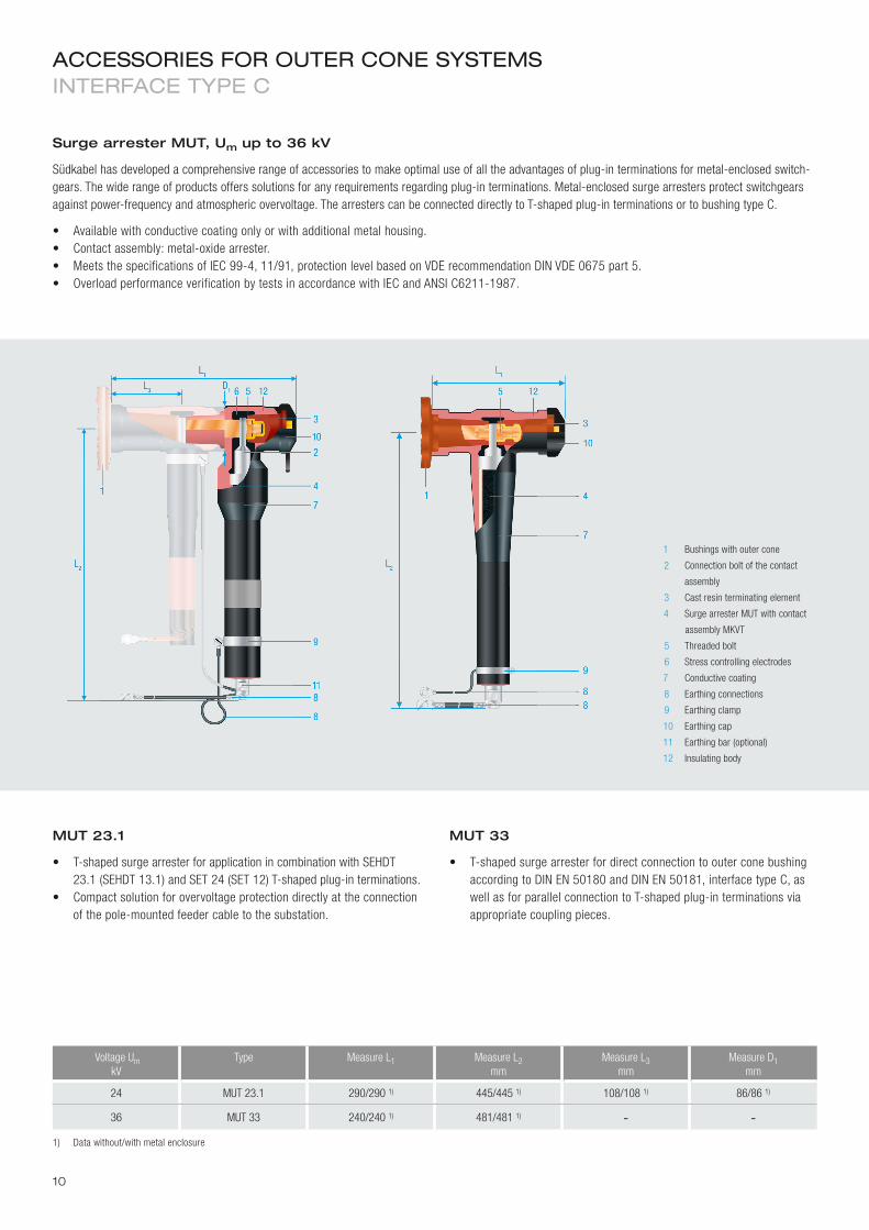
24 MUT23.1 290/290 1) 445/445 1) 108/108 1) 86/86 1)
36 MUT33 240/240 1) 481/481 1) - -1) Datawithout/withmetalenclosure
aCCessories for ouTer Cone sysTems inTerfaCe TyPe C
MUT 23.1
• T-shapedsurgearresterforapplicationincombinationwithSEHDT23.1(SEHDT13.1)andSET24(SET12)T-shapedplug-interminations.
• Compactsolutionforovervoltageprotectiondirectlyattheconnection of the pole-mounted feeder cable to the substation.
MUT 33
• T-shapedsurgearresterfordirectconnectiontoouterconebushingaccordingtoDINEN50180andDINEN50181,interfacetypeC,aswell as for parallel connection to T-shaped plug-in terminations via appropriate coupling pieces.
Surge arrester MUT, Um up to 36 kV
Südkabel has developed a comprehensive range of accessories to make optimal use of all the advantages of plug-in terminations for metal-enclosed switch-gears.Thewiderangeofproductsofferssolutionsforanyrequirementsregardingplug-interminations.Metal-enclosedsurgearrestersprotectswitchgearsagainstpower-frequencyandatmosphericovervoltage.ThearresterscanbeconnecteddirectlytoT-shapedplug-interminationsortobushingtypeC.
• Availablewithconductivecoatingonlyorwithadditionalmetalhousing.• Contactassembly:metal-oxidearrester.• MeetsthespecificationsofIEC99-4,11/91,protectionlevelbasedonVDErecommendationDINVDE0675part5.• OverloadperformanceverificationbytestsinaccordancewithIECandANSIC6211-1987.
1 Bushings with outer cone
2 Connectionboltofthecontact
assembly
3 Castresinterminatingelement
4 SurgearresterMUTwithcontact
assemblyMKVT
5 Threaded bolt
6 Stress controlling electrodes
7 Conductivecoating
8 Earthing connections
9 Earthing clamp
10 Earthing cap
11 Earthingbar(optional)
12 Insulating body
10

ACCESSORIESFOROUTERCONESySTEMS
Metal-oxidesurgearresterMKTVcontactassembly
MUT23.12)/MUT333)
6 12 18 20 22 24 30 36
ContinuousloadvoltageUC(kVrms 1)) 6 12 18 20 22 24 30 36
RatedVoltage(kVrms) 7.5 15 22.5 25 27.5 30 37.5 45
Rateddischargecurrent(kApv) 10 10 10 10 10 10 10 10
Maximumdischargecurrent(kApv) 65 65 65 65 65 65 65 65
Rect. wave strength, 2000 µsec A pv 250 250 250 250 250 250 250 250
Energyabsorptioncapacityatrect.wavestrengthkJ/kVUC 1.5 1.5 1.5 1.5 1.5 1.5 1.5 1.5
EnergyabsorptioncapacityathighimpulsecurrentkJ/kVUC 2.6 2.6 2.6 2.6 2.6 2.6 2.6 2.6
Short circuit current up to kA 16 16 16 16 16 16 16 16
DischargevoltageUp(peakvalue)
with1/10µsecwaveat5kA(kVpv) 21.8 43.6 65.3 72.6 79.8 87.1 108.9 130.6
with1/10µsecwaveat10kA(kVpv) 24.0 48.0 72.0 80.0 88.0 96.0 120.0 144.0
with8/20µsecwaveat1kA(kVpv) 17.4 34.8 52.1 57.9 63.7 69.5 86.8 104.2
with8/20µsecwaveat2.5kA(kVpv) 18.6 37.1 55.6 61.8 68.0 74.1 92.7 111.2
with8/20µsecwaveat5kA(kVpv) 19.5 39.0 58.5 65.0 71.5 78.0 97.5 117.0
with8/20µsecwaveat10kA(kVpv) 21.5 42.9 64.4 71.5 78.7 85.8 107.3 128.7
with8/20µsecwaveat20kA(kVpv) 23.8 47.6 71.4 79.3 87.3 95.2 119.0 142.8
mitWelle30/60µsbei100A(kVsw) 14.9 29.7 44.5 49.4 54.4 59.3 74.1 89.0
with30/60µsecwaveat250A(kVpv) 15.5 30.9 46.3 51.4 56.5 61.7 77.1 92.5
with30/60µsecwaveat500A(kVpv) 16.0 32.0 48.0 53.3 58.7 64.0 80.0 96.0
with30/60µsecwaveat1000A(kVpv) 16.8 33.6 50.4 55.9 61.5 67.1 83.9 100.7
1) Furtheroperatingvoltagesonrequest2) MUT23.1forvoltagesupto24kV3) MUT33forvoltagesupto36kV
Definitions
ThemaximumpermissiblecontinuousoperatingvoltageUC(MCOV) is the highest power-frequency voltage the arrester can withstand on a continual basis. This value is specified in kV as an r.m.s. value.
The energy absorption capacity E is the maximum permissible electrical energyexpressedinkJperkVUC that the surge arrester can absorb in total without its thermal stability being endangered. The energy absorption capacity is temperature-dependent and is specifiedforanambienttemperatureof45°C.
Explanation of the protection characteristics
Gap-free arresters have no sparkover voltage but only a discharge voltageUp. This represents the voltage between the arrester terminals while a power pulse current passes through.
The 1/10 µsec current wave at a rated discharge current of 10 kA represents very steep overvoltage waves. The associated discharge voltage is comparable to the front sparkover voltage of conventional ar-resters with spark gaps.
The 8/20 µsec pulse wave at a peak value of 10 kA results in a discharge voltage approximately corresponding to the protection level in case of lightning impulses.
The 30/60 µsec current wave corresponds to a steep switching impulse voltage.Withthiswaveform,thedischargevoltageat1kAresultsinap-proximately the protection level for switching impulse voltage stress.
The protection characteristics are sufficiently described with these three current waves.
Technical data of the contact assemblies MKVT in surge arresters MUT 23.1/MUT 33
11

aCCessories for ouTer Cone sysTems
Insulating termination IS 21
• Forplug-interminationtypeA.• Suitableforupto24kV.
Insulating termination IS 23.1
• Forplug-interminationtypeBandC.• Suitableforupto36kV.
Earthing accessory ER 21
• Forplug-interminationtypeA.
Earthing accessory ER 22 / ER 23
• Forplug-interminationtypeBandC.
1 Contacttube
2 Castresinterminatingelement
3 Mountingplatewithboringsforfasten-
ing the insulating termination to plug-in
terminations
1 Earthing pin with contact tube for plug-in
or screwed contact
2 Polyamidebody
3 Mountingplatewithboringsforfastening
the earthing accessories to plug-in
terminations with plug-in contacts
4 Coppercompressioncablelug,tin-plated
5 ESUyearthingcable(50mm2 for bushing
type A, 95 mm2forbushingtypeBandC),
cable length 500 mm, counterpart with
copper compression cable lug with strap
boring(10.5mmforbushingtypeA
and13mmforbushingtypeBandC).
AlternativelyavailablewithballpinØ20mm.
Surge-proof insulating terminations ISUm up to 36 kV
Surge-proof insulating terminations are used for surge-proof and shock-proof insulation of plug-in terminations which are disconnected from the switchgear or the transformer.
Earthing accessories ER
Earthing accessories are used for short circuit-proof earthing of plug-in terminations.
12

Coupling piece KU 21
• Insulatingmaterial:castresin.• Forinterconnectingplug-interminationsof
interface type A up to 24 kV.
Coupling piece KU 23.2 / 23
• Insulatingmaterial:siliconerubber.• ForconnectingSET12/24(SEHDT13.1/23.1)
plug-in terminations to plug-in terminations ofinterfacetypeCwithatleastone combined type SET plug-in termination.
Coupling piece KU 33
• Insulatingmaterial:siliconerubber.• Forinterconnectingplug-interminations
ofinterfacetypeCupto36kV.
1 Copperconnectionbolt
2 Lamellatedcontact
3 M16thread
4 Castresininsulatingbody
5 Silicone rubber insulating body
6 Stress controlling electrode
7 Earthing connection
Coupling pieces KU Um up to 36 kV
Couplingpiecesareusedincombinationwithshapedplug-interminationsforsurge-proofandshock-proofconnectionofcomponentssuchasparallelcablesor surge arresters. It is also possible to provide cable connections or highly-flexible cable connections in the form of detachable sections using coupling pieces and appropriate plug-in terminations. Special coupling pieces are available for connecting plug-in terminations for different connection types.
ACCESSORIESFOROUTERCONESySTEMS
13

aCCessories for ouTer Cone sysTems
Test bushing PR 23.1
• ForT-shapedSETandSEHDTplug-interminationsofinterface typeCupto24kV.
• T-shapedplug-interminationscanremainconnectedtothesystem.• Assemblyofthetestbushingontherearcastresinterminatingele-
ment of the T-shaped plug-in termination.
Test bushing PR 23.1 with extension
• ForT-shapedSETandSEHDTplug-interminationsofinterface typeCupto36kV.
• T-shapedplug-interminationscanremainconnectedtothesystem.• Assemblyofthetestbushingontherearcastresinterminatingele-
ment of the T-shaped plug-in termination.
Test bushing PRUm up to 36 kV
Testbushingsareusedtoperformvoltagetests(cabletests, faultlocating)oncablesthatareconnectedwithplug-interminations.
Wall bushing WA 23Um up to 24 kV
ThewallbushingWA23enablesthetransitionfrommediumvoltageoverhead lines to metal-enclosed termination systems up to 24 kV inside masonry-enclosed substations.
• Ontheoutside:outdoorinsulatormadeofepoxycastresin.• Insidethestation:outerconebushingaccordingtoEN50180and
DIN EN 50181 with screw-type contact.• Metal-enclosedthroughinsulatorforwallthicknessofupto25cm.• Forplug-interminationsofinterfacetypeC.
Post insulator STF 21Um up to 24 kV
ThepostinsulatorSTF21isusedtoconnectsingle-coreXLPEcablestoouter cone bushing type A via conventional terminations.
1 Connectingbolt
2 Thread for testing lead connection
3 M16threadforthethreadedboltof
the plug-in termination
4 Insulating body made of cast resin
5 Insulating body made of silicone rubber
6 Extension
1 Bushing with outer cone
interfacetypeC
2 Fixing elements for earthing of
the metal housing and stress
controlling electrode
3 Metalhousing
4 Flange boring for fastening the wall
bushing at the wall surface of the
masonry-enclosed substation
5 Epoxy cast resin outdoor insulator
6 Radiation hood of the outdoor insulator
7 M16connectionboltforoverhead-line
connection
1 Bushing with outer cone
interface type A
2 Threaded bolt for termination connection
3 Contactpin
4 Castresininsulator(outdoorversion)
5 Insulating body made of silicone rubber
with smoothing tube
6 Support ring with stress controlling
electrode
7 Support tube with mounting flange
8 Mountingplate
14

1 Bushings
2 Insulating body
3 Metalhousing
4 Castresinterminatingelement
5 Conductivecoating
6 Earthing cap
7 Earthing connection
Terminating cap SP 21
• ForbushingstypeAupto24kV.• ConnectorbailholderaccordingtoDINEN50180and
DIN EN 50181 required.
Terminating cap SP 23.1
• ForbushingstypeBandCupto24kV.• ConnectorbailholderaccordingtoDINEN50180and
DIN EN 50181 required.
Terminating cap SP 33
• ForbushingstypeCupto36kV.• ConnectorbailholderaccordingtoDINEN50180and
DIN EN 50181 required.
Terminating cap AD 23.1 SP
• ForbushingstypeCupto24kV.• Noconnectorbailholderrequired.• IncludestheadapterAD23.1*),threadedpin,castresinterminating
element and earthing cap.
*) FordirectswitchgearconnectionofaccessorypartsthatcanonlybeassembledonSET.
Surge-proof terminating caps SPUm up to 36 kV
Terminating caps are used for surge-proof and shock-proof insulation of bushings on distribution transformers and metal-enclosed switchgears.
ACCESSORIESFOROUTERCONESySTEMS
15

inner Cone sysTem Cable Terminals
Bushings
The standards EN 50180 and EN 50181 define four types of interfaces for the inner cone system up to 52 kV of which only three are relevant in practice.
Its bushings type 1, type 2 and type 3 mainly vary in dimensions:
For the inner cone system too, particularly used in power switchgears and power transformers, Südkabel has developed a designated compatible product range for flexible application.
The basic designs of all inner cone plug-in terminations can be compared. The size of the insulator and the design of the individual plug-in contacts, however, vary according to the size of the respective bushing. The plug-in contact consists of a lamellated contact that is connected to the conductor with a cone clamp. A pressure spring between insulating body and mount-ing flange ensures compensation of the expansion of the silicone compo-nents during operation. It also provides sufficient contact pressure at the interface between the silicone component and cast resin bushing.
Designation Rated current Max.operatingvoltage
Contactelement Measure
A B C D E
Interface type 1 400 – 630 A 36 kV Lamellatedcontact 137 mm 63.5 mm 83 mm 95 mm 82.3 mm
Interface type 2 800 A 42 kV Lamellatedcontact 137 mm 69.5 mm 83 mm 102 mm 88.3 mm
Interface type 3 1250 A 52 kV Lamellatedcontact 185 mm 92.5 mm 110 mm 130 mm 112.6 mm
16

aCCessories for inner Cone sysTems inTerfaCe TyPe 1 – 3
1 Pressureringwithlamellatedcontact
2 Coneclamp
3 Stop disc
4 Silicone rubber insulator with
integrated stress control element
5 Pressurespring
6 Silumin entry gland with
mounting flange
7 Earthing connection
8 Switchgear interface
9 Pressurediscwithmountingscrews
Inner cone plug-in termination SEIK Um up to 52 kV
• Straightplug-interminationsforconnectionofXPLEcables12–52kV to metal-enclosed switchgears and transformers.
• Capacitivevoltagetap-offonrequest.• Enclosuretestavailablewithoptionalinsulatingwrap. • TheinsulatingsealstypeISIKserveforsurge-proofandshock-proof
termination of bushings for inner cone systems.
TheSEIKinnerconeplug-interminationsserve for bushings according to DIN EN 50180 and DIN EN 50181, interface types 1, 2 and 3.
Type Interface type
Rated current load of the bushing
A
Permissiblewirediameter 1)
mm
Voltage
kV
Conductordiameterassignmentofthe insulator 1)
mm2
Measure L
mm
MeasureD1
mm
MeasureD2
mm
SEIK 13 / 23 / 33 1 630 13.0 – 33.6 12 / 24 / 36 35 – 240 / 25 – 240 / 35 – 150 80 - -
ISIK 13 / 23 / 33 1 - - 12 / 24 / 36 - - 95 112
SEIK 14 / 24 / 34 2 800 13.0 – 41.4 12 / 24 / 36 / 42 35 – 300 / 25 – 300 / 35 – 300 / 2) 80 - -
ISIK 14 / 24 / 34 2 - - 12 / 24 / 36 / 42 - - 102 119
SEIK 15 / 25 / 35 / 55 3 1250 20.3 – 52.0 12 / 24 / 36 / 52 150 – 630 / 70 – 630 / 35 – 630 / 2) 80 - -
ISIK 15 / 25 / 35 3 - - 12 / 24 / 36 / 52 - - 130 147
1) ForcablesaccordingtoDINVDE0276-6202) Onrequest
TheproductrangeISIKoffersdifferentvariations of insulating seals for all sizes of bushings. TheinnerconeinsulatingsealISIKcanbeinstalled on all bushings according to DIN EN 50180 and DIN EN 50181, interface types 1, 2 and 3.
Inner cone insulating seal ISIKUm up to 52 kV
• Forsurge-proofandshock-proofterminationsofbushingsforinner cone systems.
• AllmodelsbyfarcomplywiththerequirementsofDINVDE0278-629-1.
17

PreassembledlinksareXLPEcablesorflexibleEPR-insulatedtrailingcablesthatarefactory-equippedwith terminations. They are primarily used for connections between transformers and switchgears.
Preassembled cable and high flexible cable-links 12 – 36 kV
• Theminimumbendingradiusofflexibletrailingcablesisideal for installation in narrow areas.
• Rationalizationofsubstationassemblyasnoinstallationonsite is necessary.
• Theaccessoryequipmentofthelinkscanbefreelychosenasanytypeof termination and plug-in connectors admissible for cables or flexible cable links can be combined.
• Outputcheckonrequest.
Type Admissible current carrying
capacity 1)
A
Short circuit cur-
rent 1sKA
Outerdiameter
mm
Minimumbending radiusmm
Trailing cable 24 kV 2)
NTMCWOEU1x35mm² 240 5.0 29.5 145
NTMCWOEU1x50mm² 300 7.2 31.5 155
Cable24kV2)
N2XSy1x35mm² 235 5.0 30 450
N2XSy1x50mm² 282 7.2 34 550
1) Airinstallationatanambienttemperatureof30°C2) Furtherdiametersonrequest
aCCessories for ouTer and inner Cone Plug-in TerminaTions
Sheath cutter WM 20.1
SheathcuttertoremovePEover-sheathsandXLPEinsulationsfrom medium voltage cables.
Cable stripper WL 20.1
Cablestripperforremovalofthefix-bondedouterinsulationscreenof XLPE-insulatedmediumvoltagecables.
Indicator unit for capacitive voltage tap
The indicator unit enables long-term use of the voltage tap for safe and reliable display that the plug-in termination is de-energised. The indicator unit can be adaptedtodifferentdesignsbymeansofdesignatedadjustmentkits.
Further accessories
Productsforcableinstallationandlaying:
• Earthingmaterialforcableswithcoppertapescreens.• Shrinkablecablebreakoutforthree-coreXLPEcables.• Cablebundlingtapeforshortcircuit-proofbundlingof
single-core cables.• RUK500cleaningtissueimpregnatedwithcablecleaningagent
for cable sheaths and insulations.
18

Type K
(mechanicalshort-circuitstability10.000N)forfixingofsingleand multi-core cables.
Type KP
(mechanicalshort-circuitstability25.000N)forfixingofsingle-corecables in trefoil formation for high short-circuit stress levels.
Type KS
(mechanicalshort-circuitstability12.500N)forfixingofsingle-corecables in trefoil formation.
Type KR
(mechanicalshort-circuitstability20.000N)forfixingofsingleand multi-corecables(individualfixing).
Glassfibrereinforcedpolyamidefixingclampsforsafemountingofcablesonpoles,instationsandcableducts.
Type K26/38 K36/52 K50/75 K66/90 KP29/41 KP39/53 KS25/36 KS33/46 KR75/100 KR100/130 KR130/160
suitable for cable diameters of [mm]
26 – 38 36 – 52 50 – 75 66 – 90 29 – 41 39 – 53 25 – 36 33 – 46 75 – 100 100 – 130 130 – 160
MeasureL1 90 105 126 158 172 190 150 170 180 210 250
MeasureL2 60 75 95 120 125 145 110 130 150 175 210
MeasureB 60 60 60 70 80 80 80 80 77 97 97
Measured 12 12 12 14 14 14 12 12 14 14 18
ACCESSORIESFOROUTERANDINNERCONEPLUG-INTERMINATIONS
19
ww
w.ja
nu
s-w
a.d
e
Südkabel 3003 E
Südkabel GmbH
Rhenaniastrasse12-30|68199Mannheim Phone:+49621850701|Fax:+496218507294 E-mail: [email protected]
www.suedkabel.de
Note:Wereservetherighttomaketechnicalchangesormodifythecontentsofthisdocumentwithoutpriornotice.Withregardtopurchaseorders,theagreedparticularsshallprevail.Südkabeldoesnotacceptanyresponsibilitywhatsoeverforpotentialerrorsorpossiblelackofinformationinthisdocument.Wereserveallrightsinthisdocumentandinthesubjectmatterandillustrationscontainedtherein.Anyreproduction–inwholeorinpart– is forbidden without Südkabel’s prior written consent.
Copyright©2013Südkabel.Allrightsreserved.
Cables
• XLPE-insulatedcablesfrom6kVto500kV
Accessories for medium, high and extra-high voltage cables
• Outdoorterminations
• Conventionalandplug-interminationsforSF6 switchgears and transformers
• CableJoints
• Plug-interminationsforouterandinnerconesystems
• Mediumvoltagecablelinks
• Accessoriesforelectrostaticprecipitatorcables
Cable systems
• TurnkeyXLPE-insulatedcablesystemsupto500kV
Services
• Consultingserviceonapplicationrelatedquestions
• Trainingforinstallationpersonnel
• Cablelayingandsupervisionoflaying
• Installationofaccessories
• Commissioning
• Aftersalesservices
our offer


![XLPE Insulated Cables[1]](https://img.pdfslide.net/doc/110x75/54651acaaf79596e458b492d/xlpe-insulated-cables1.jpg)