Embed Size (px)
Citation preview
Point 5 - Cooling Network - Key
Primary Water
Chilled Water
Mixed Water
Eau Bruite
Standard Power
DieselBackup
Comp Air
Primary Water at 20-25C – Produced by Cooling Towers
Chilled Water at 5C – Produced by Chillers
Mixed Water at 14-18C – Produced by Chillers, Heat Exchangers or by mixing Primary & Chilled water
Eau Bruite – Supplied for refilling of circuits & the fire fighting network
Demi Water Demi Water at 16-18C – Produced by Heat Exchangers from either Chilled or Mixed water – Divided into Copper and Aluminum types
Standard Power – Electrical power for pumps, valves & chillers
Diesel Backup Power – Electrical power for control panels & cubicles
Compressed Air – Instrument Quality or Standard air for actuators and control valves
Pri
ma
ry W
ate
rM
ixe
d +
Ch
ille
d W
ate
rM
ixe
d +
Ch
ille
d +
De
mi
Wa
ter
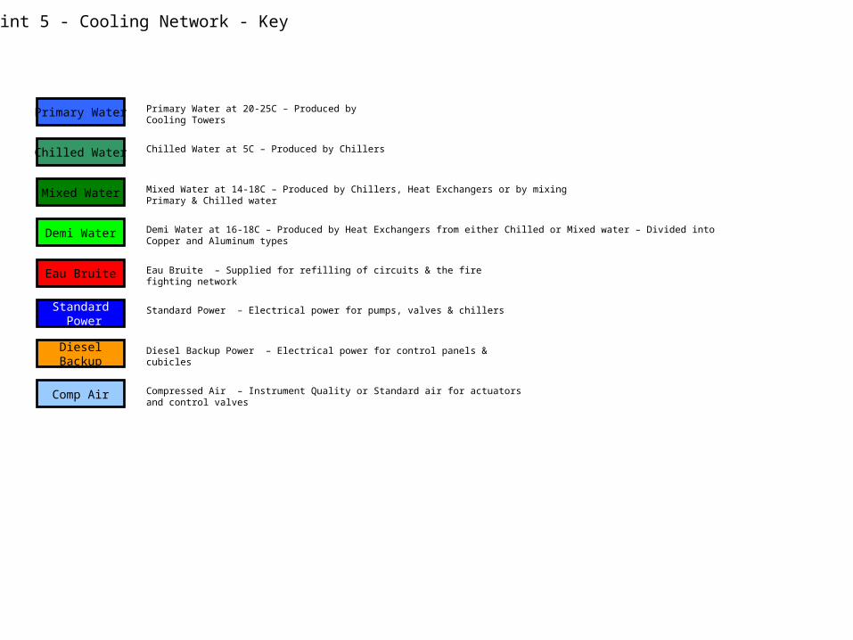
Point 5 - Cooling Network SF5 Cooling Towers
SUX5 Chilled Water Production
USC55 CV Zone Cooling Distribution
CHILLED5 C
MIXED14-15 C
PRIMARY22-25 C
CHILLED - 7 C DEMI - 18C MIXED -16C
DEMI WATERPOINT 4
DEMI WATERPOINT 4
PM56EAU BRUITE
SH5Comp Air
SU5Comp Air
Standard Power
DieselBackup
SF5 Cooling Towers
SUX5 Chilled Water Production
USC55 CV Zone Cooling Distribution
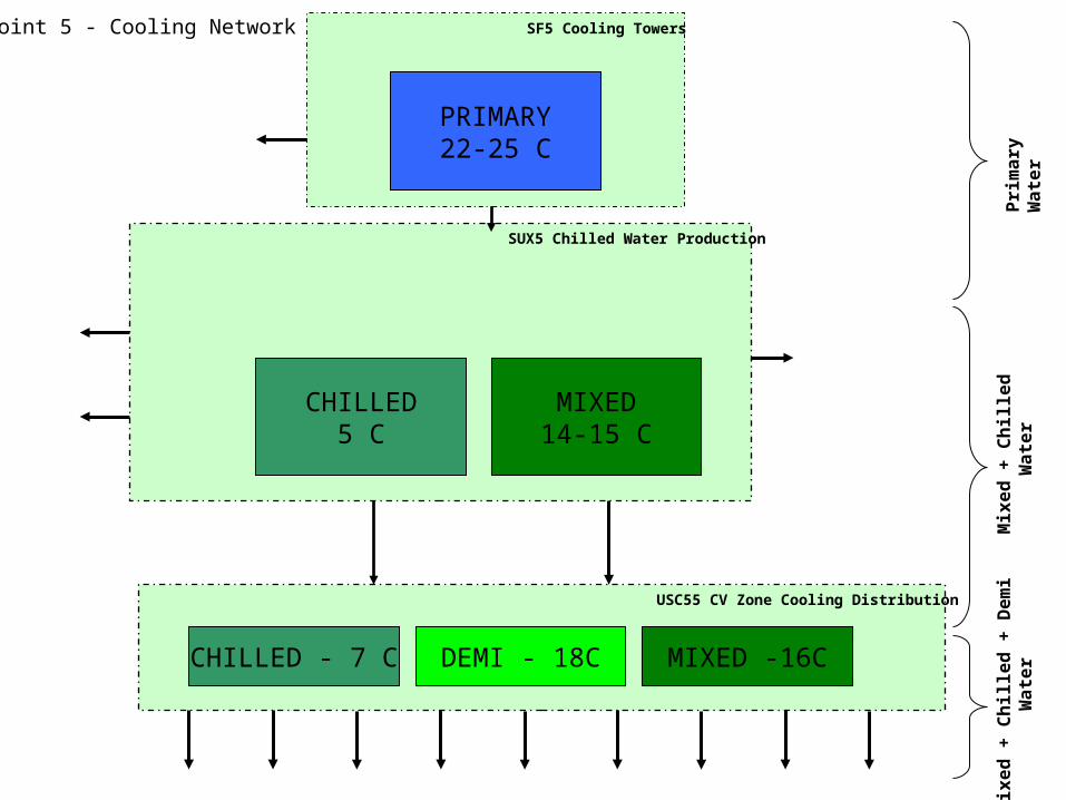
Point 5 –Security of Supply
Instrument AirTo CV Zone, Tracker & CRYO
Standard AirTo Eau Bruite, Gas Room & UXC
Eau Bruite for Refilling of all circuits & Fire Fighting network
Demi Water supply for Refilling of circuits in UXC
Diesel Backup Power only for supply of control Panels
Standard Power supply of pumps & Chillers
Failure of cooling towers results in loss of primary water to chilled water production, Interlocks stop the chillers.
1-2 hours before underground areas are affected.
Failure of Eau Bruite will stop circuits when circuits are required to be refilled. Failure of power will stop cooling towers, however system shall restart automatically on return of power
Failure of chillers results in loss of chilled or mixed water. 1-2 hours before users in underground areas are affected, depending on current demand
Failure of distribution pumps will affect users within 30 mins.
Failure of Eau Bruite will stop circuits when circuits are required to be refilledFailure of power will stop chillers & distribution circuits, however system shall restart automatically on return of power
Failure of distribution pumps will result in a loss of cooling immediately.
Failure of Eau Bruite or Demi Water supply will stop circuits when circuits are required to be refilled. Failure of power will stop chillers & distribution circuits, however system shall restart automatically on return of power. Failure of instrument air will stop circuits on low pressure condition
PM56EAU BRUITE
SH5Comp Air
SU5Comp Air
SUX5SX5
SR5 SGX5SX5
SCX5
DEMI WATERPOINT 4 COLD BOXRACKSECALMUONSEND CAPYOKEBUS BARHVACTRACKER
DEMI WATERPOINT 4
SH5
SF5 Cooling Towers
SUX5 Chilled Water Production
USC55 CV Zone Cooling Distribution
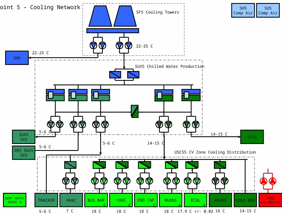
Point 5 – Cooling Network
5-6 C
5-6 C5-6 C 14-15 C
14-15 C
5-6 C 7 C 18 C 18 C 18 C 18 C 17.9 C +/- 0.02 16 C 14-15 C
22-25 C
22-25 C
c c c A A
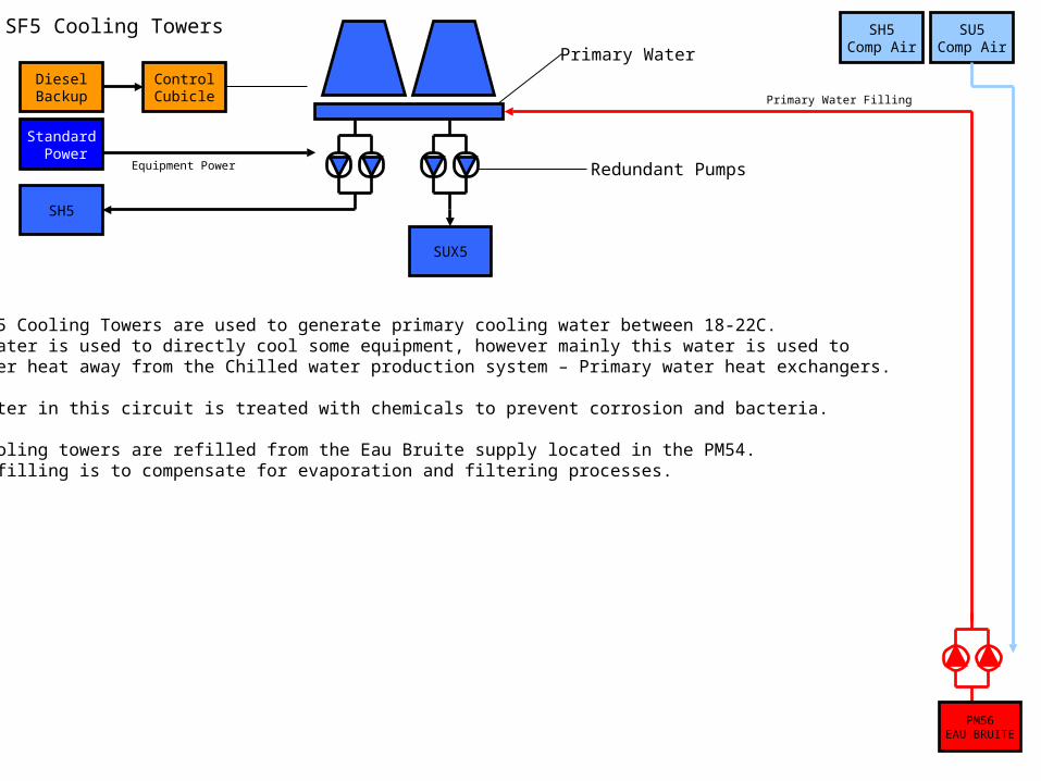
SF5 Cooling TowersPrimary Water
Redundant Pumps
SH5
SUX5
PM56EAU BRUITE
Standard Power
DieselBackup
ControlCubicle
Equipment Power
SH5Comp Air
SU5Comp Air
The SF5 Cooling Towers are used to generate primary cooling water between 18-22C.This water is used to directly cool some equipment, however mainly this water is used to Transfer heat away from the Chilled water production system – Primary water heat exchangers.
The water in this circuit is treated with chemicals to prevent corrosion and bacteria.
The Cooling towers are refilled from the Eau Bruite supply located in the PM54. The refilling is to compensate for evaporation and filtering processes.
Primary Water Filling

PM56EAU BRUITE
SH5Comp Air
SU5Comp Air
SUX5SX5
SR5 SGX5SX5
SCX5
DEMI WATERPOINT 4 COLD BOXRACKSECALMUONSEND CAPYOKEBUS BARHVACTRACKER
DEMI WATERPOINT 4
SH5
SF5 Cooling Towers
SUX5 Chilled Water Production
USC55 CV Zone Cooling Distribution
Point 5 – Cooling Network
SUX5SX5
SR5 SGX5SX5
SCX5
PM56EAU BRUITE
USC55Chilled Water
USC55Mixed Water
Standard Power
DieselBackup
ControlCubicle
Equipment Power
3.3KV Power
Chiller Power
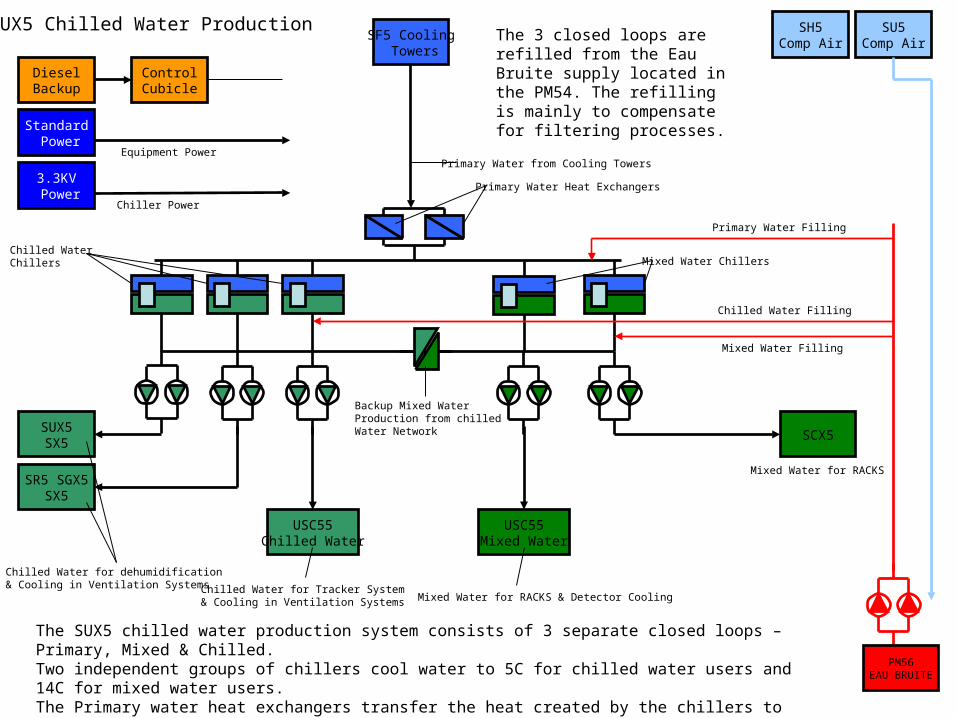
SUX5 Chilled Water ProductionSF5 Cooling
Towers
Primary Water Filling
Mixed Water Filling
Chilled Water Filling
Primary Water from Cooling Towers
Primary Water Heat Exchangers
Mixed Water ChillersChilled Water Chillers
Backup Mixed WaterProduction from chilled Water Network
Chilled Water for dehumidification & Cooling in Ventilation Systems Chilled Water for Tracker System
& Cooling in Ventilation Systems Mixed Water for RACKS & Detector Cooling
Mixed Water for RACKS
SH5Comp Air
SU5Comp Air
The SUX5 chilled water production system consists of 3 separate closed loops – Primary, Mixed & Chilled.Two independent groups of chillers cool water to 5C for chilled water users and 14C for mixed water users.The Primary water heat exchangers transfer the heat created by the chillers to the SF5 cooling towers.5 groups of distribution pumps then supply this cooled water to the users.
The 3 closed loops are refilled from the Eau Bruite supply located in the PM54. The refilling is mainly to compensate for filtering processes.
PM56EAU BRUITE
SH5Comp Air
SU5Comp Air
SUX5SX5
SR5 SGX5SX5
SCX5
DEMI WATERPOINT 4 COLD BOXRACKSECALMUONSEND CAPYOKEBUS BARHVACTRACKER
DEMI WATERPOINT 4
SH5
SF5 Cooling Towers
SUX5 Chilled Water Production
USC55 CV Zone Cooling Distribution
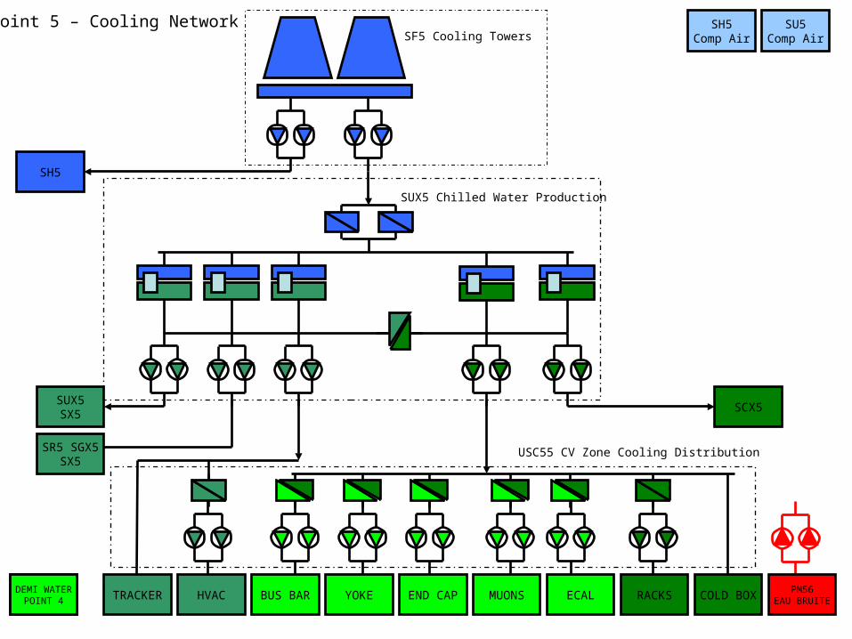
Point 5 – Cooling Network
COLD BOXRACKSECAL
AluminumMUONS
AluminumEND CAP
CopperYOKECopper
BUS BARCopper
HVACTRACKERPM56
EAU BRUITE
SUX5Chilled Water
SUX5Mixed Water
DEMI WATERPOINT 4
Standard Power
DieselBackup
ControlCubicle
Equipment Power
SH5Comp Air
SU5Comp Air
USC55 Cooling Distribution
Chilled Water from SUX5 Chilled Water Production at 5C
Mixed Water from SUX5 Chilled Water Production at 14C Demineralised Water Filling Chilled Water
Filling
Mixed Water Filling
Instrument AirFor Operating ValvesShared with Tracker & Cyro
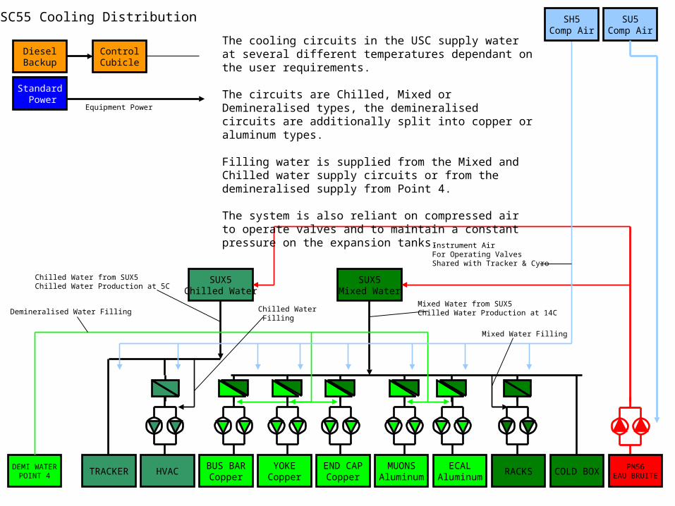
The cooling circuits in the USC supply water at several different temperatures dependant on the user requirements.
The circuits are Chilled, Mixed or Demineralised types, the demineralised circuits are additionally split into copper or aluminum types.
Filling water is supplied from the Mixed and Chilled water supply circuits or from the demineralised supply from Point 4.
The system is also reliant on compressed air to operate valves and to maintain a constant pressure on the expansion tanks.
PM56EAU BRUITE
SUX5 Primary Water Filling
SUX5 Mixed Water Filling
SU5Comp Air
SF5 Primary Water Basin
SUX5 Chilled Water Filling
Fire Fighting Network
UXC Fire Fighting Basin (Foam)
Point 5 – Eau Bruite & Demi Water
DEMI WATERPOINT 4
CV Zone – Demi Water Filling
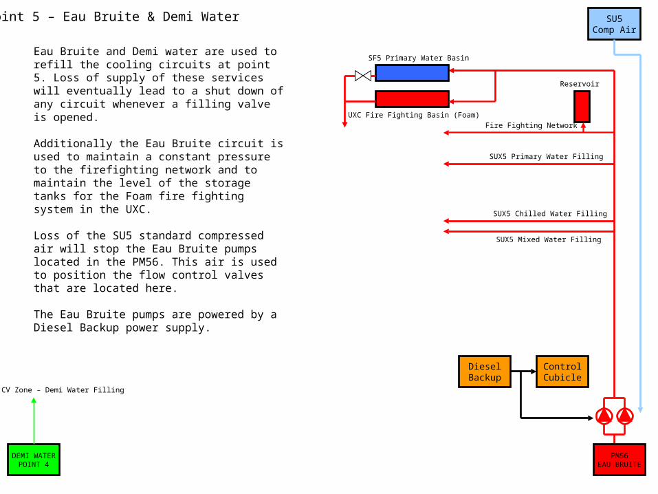
Eau Bruite and Demi water are used to refill the cooling circuits at point 5. Loss of supply of these services will eventually lead to a shut down of any circuit whenever a filling valve is opened.
Additionally the Eau Bruite circuit is used to maintain a constant pressure to the firefighting network and to maintain the level of the storage tanks for the Foam fire fighting system in the UXC.
Loss of the SU5 standard compressed air will stop the Eau Bruite pumps located in the PM56. This air is used to position the flow control valves that are located here.
The Eau Bruite pumps are powered by a Diesel Backup power supply.
Reservoir
DieselBackup
ControlCubicle
SU5Comp Air
Point 5 – Compressed Air Network
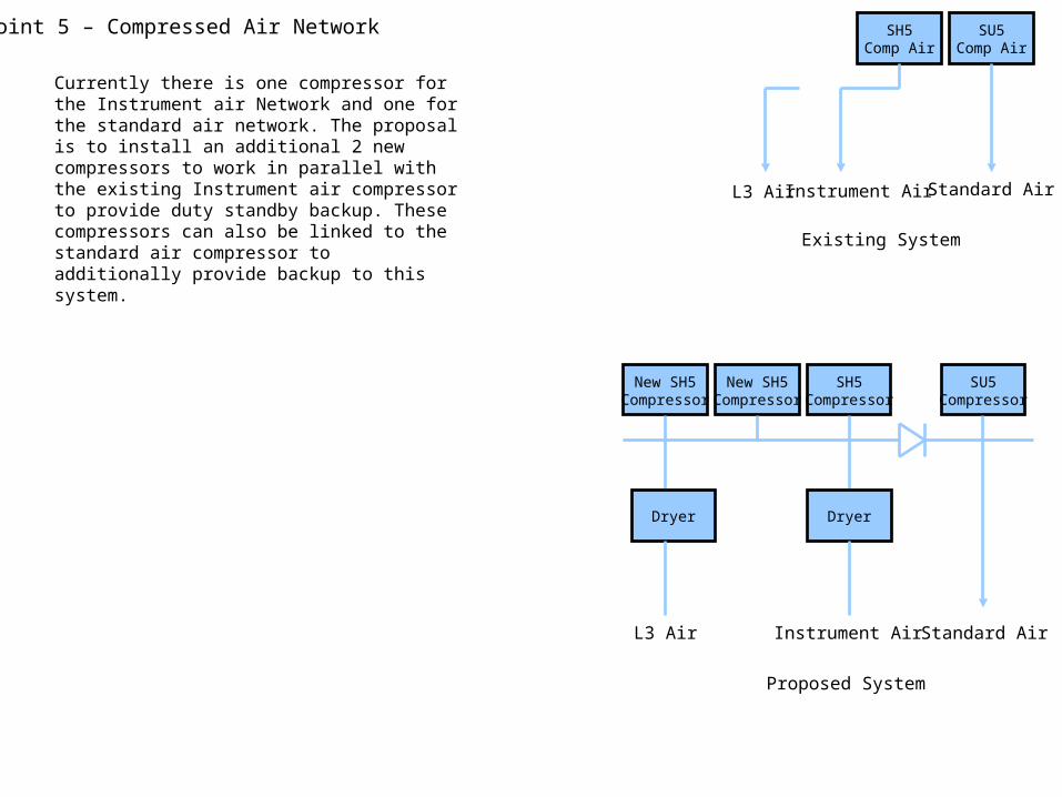
Currently there is one compressor for the Instrument air Network and one for the standard air network. The proposal is to install an additional 2 new compressors to work in parallel with the existing Instrument air compressor to provide duty standby backup. These compressors can also be linked to the standard air compressor to additionally provide backup to this system.
SH5Comp Air
L3 Air Instrument Air Standard Air
New SH5Compressor
New SH5Compressor
SH5Compressor
SU5Compressor
Dryer Dryer
L3 Air Instrument Air Standard Air
Existing System
Proposed System
DCS
VGTCCOOLUSC55
OPC SERVER
GTCCOOLUSC55
TECHNICAL NETWORK
PCvue
Remote PC
PCvue Server
LOCAL TOUCH PANEL
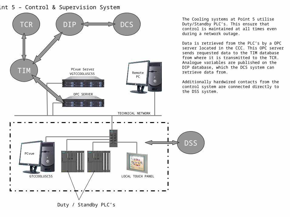
The Cooling systems at Point 5 utilise Duty/Standby PLC’s. This ensure that control is maintained at all times even during a network outage.
Data is retrieved from the PLC’s by a OPC server located in the CCC. This OPC server sends requested data to the TIM database from where it is transmitted to the TCR. Analogue variables are published on the DIP database, which the DCS system can retrieve data from.
Additionally hardwired contacts from the control system are connected directly to the DSS system.TIM
Duty / Standby PLC’s
TCR DIP
DSS
Point 5 – Control & Supervision System


![[25c]Anestesicos Generales](https://img.pdfslide.net/doc/110x75/55cf968a550346d0338c2a87/25canestesicos-generales.jpg)