Embed Size (px)
Citation preview
Polychaete-like Pedundulatory Robotic Locomotion
Michael Sfakiotakis, Dimitris P. Tsakiris and Kostas Karakasiliotis
Abstract—The polychaete annelid marine worms propelthemselves in a variety of challenging locomotion environmentsby a unique form of tail-to-head body undulations, combinedwith the synchronized action of numerous parapodial lateralappendages. This combined parapodial and undulatory modeof locomotion is termed pedundulatory in the present work.Robotic analogues of this type of locomotion are being studied,both in simulation, and via experiments with biomimetic roboticprototypes, which combine undulatory movements of theirmulti-link body with appropriately coordinated parapodial linkoscillations. Extensive experimental studies of locomotion onsand demonstrate the potential of the pedundulatory roboticprototypes, especially their rich gait repertoire and their en-hanced performance compared to robotic prototypes relyingonly on body undulations.
Keywords - biomimetic robotics, undulatory locomotion,legged locomotion, motion control, polychaete annelids.
I. INTRODUCTION
Our previous work [1]–[3] has identified, and startedreplicating, an intriguing biological paradigm of locomotionin a variety of unstructured environments, namely that of thepolychaete annelid segmented marine worms: they are livingin the depths of the ocean, floating near the surface, or bur-rowing in the mud and sand of the seashore. Their adaptationto so diverse habitats impacts directly their morphology, sen-sory apparatus and nervous system structure (Fig. 1a). Theirlocomotion is characterized by the combination of a uniqueform of tail-to-head body undulations (opposite direction ofpropagation than snakes or eels), with the rowing-like actionof their numerous active lateral appendages, called parapodia,distributed along their segmented body [4]–[6]. Roboticanalogues of the polychaete tail-to-head body undulationswere studied in [1], in the context of locomotion on sand.However, the combination of parapodial and undulatory lo-comotion, termed pedundulatory in the present work, meritsspecial attention, as it provides these worms with distinctivelocomotory modes, increasing their terrain traversing andmanipulation capabilities. If properly replicated, it couldbenefit emerging robotic applications ranging from noveldiagnostic systems for healthcare (e.g. endoscopic access tothe human gastrointestinal tract) to robotic tools for search-and-rescue operations and to planetary exploration.Robotic investigations of undulatory locomotion, has led
mostly to wheeled mechanisms for terrestrial locomotion
This work was supported in part by the European Commission, throughthe IST projects MATHESIS (FP6-027574) and VECTOR (FP6-033970).The authors are with the Institute of Computer Science, Foundation
for Research & Technology – Hellas, Vassilika Vouton, P.O. Box 1385,Heraklion, Greece {sfakios,tsakiris}@ics.forth.gr
(a)
(b)
Fig. 1. (a) Nereis virens, a polychaete annelid marine worm. (b) TheNereisbot pedundulatory robotic prototype.
over relatively smooth surfaces (e.g., [7]–[11]). Recent in-novative research efforts on non-wheeled undulatory loco-motion bring forth the importance of understanding the in-teraction of the undulatory mechanism with the environmentenabling the locomotion [1], [8], [12]–[16].Drawing inspiration from the body plan and locomotion
strategies of the polychaete annelids, we have developedseveral robotic prototypes, which combine body undulationswith the paddle-like action of active lateral parapodial ap-pendages. Sections II and III of the paper describe modelsof the mechanics and motion control of polychaete pedundu-latory locomotion, and present associated simulation studies.Section IV describes the Nereisbot pedundulatory roboticprototype (Fig. 1b), which is capable of locomotion overunstructured substrates, and allows the validation and refine-ment of these models. The locomotory advantage of usingparapodia to complement body undulations is demonstratedin Section V by robotic experiments of locomotion on sand,which also verify that our computational models captureadequately essential features of polychaete locomotion.
II. MODELING PEDUNDULATORY LOCOMOTIONThe computational models developed to study the pro-
posed locomotion strategy employ the SIMUUN simulationenvironment [17], which is based on the SimMechanicsphysical modeling toolbox of Matlab/Simulink.
A. Mechanism ModelFollowing the Nereisbot prototype design, the mechanism
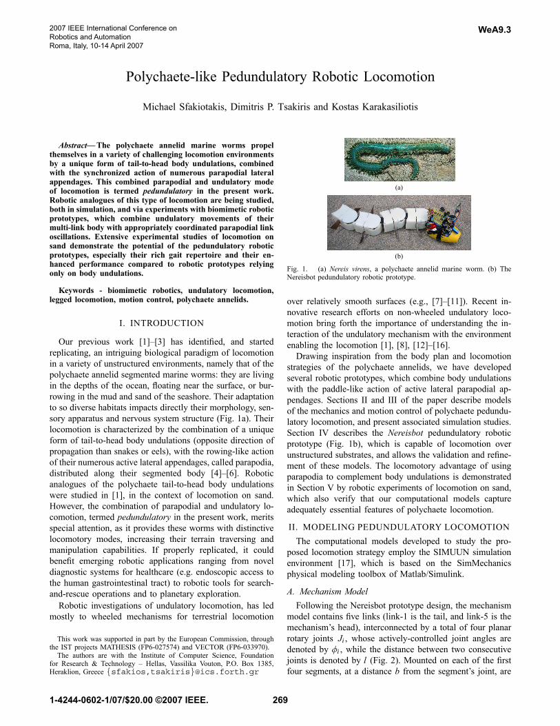
model contains five links (link-1 is the tail, and link-5 is themechanism’s head), interconnected by a total of four planarrotary joints Ji , whose actively-controlled joint angles aredenoted by φi , while the distance between two consecutivejoints is denoted by l (Fig. 2). Mounted on each of the firstfour segments, at a distance b from the segment’s joint, are
2007 IEEE International Conference onRobotics and AutomationRoma, Italy, 10-14 April 2007
WeA9.3
1-4244-0602-1/07/$20.00 ©2007 IEEE. 269
ζi
lp
χi
Head LinkJ2
l
Top view
Front view
b
J4
φ1
φ2
FN
Bi
FT
Bi
FT
Pj
FN
Pj
Fig. 2. Model of the Nereisbot prototype.
a pair of laterally placed parapodial links of length l p. Theseare connected to the segment via planar dorso-ventrally ori-ented single-degree-of-freedom rotary joints, whose angles tothe horizontal are denoted by χi and ζi . The system’s equa-tions of motion are automatically derived by the SIMUUNcomputational tools.
B. Interaction with the Environment
Locomotion of an undulating body results from the cou-pling of its internal shape changes to external motion con-straints, usually due to external frictional forces appliedthrough the interaction with the locomotion environment, re-sisting the motion of body segments. In order to approximatethe characteristics of this interaction, resistive force modelshave been developed, whereby the force on each link involvesdecoupled components in the normal and tangential directionof its motion (FN and FT , respectively), which depend on thecorresponding link velocity components vT and vN . Use ofsuch force models dates back to the analysis of anguilliformswimming in [18], variants of which have been applied toboth aquatic and terrestrial locomotion. Assuming isotropicCoulomb-like interaction with the substrate, the resistiveforce components acting on the i th body link are obtainedas FBiT = −μTmg sgn(vBiT ) and FBiN = −μNmg sgn(vBiN ),where m is the link’s mass and g is the constant of gravity,while μT and μN are the tangential and normal Coulombfriction coefficients, respectively (Fig. 2). The latter dependon the configuration and material properties both of thelinks’ contact surface and of the locomotion environment. Ingeneral, the larger the differential between these coefficients,the larger the stride length (distance traveled per undulationcycle) attainable for a given body wave. Moreover, thefriction coefficients’ ratio also determines, to a large extent,the direction of motion of the undulatory locomotor withrespect to the body wave direction [1]. Most research effortsrelated to undulatory robots have considered the eel-likemode, which, for the friction model at hand, correspondsto μN/μT 1, resulting in devices that achieve forwardpropulsion by head-to-tail body waves (e.g., [7]–[9], [13]–[16]). By contrast, when resistance in the tangential directionof link motion is higher than resistance in the normal direc-tion (corresponding to μN/μT < 1), the overall locomotionis along the body wave direction, so that forward motionis by tail-to-head waves; we focus here on this polychaete-like mode of undulatory locomotion. It should be noted that,for the Coulomb model employed, when μN/μT 1, the
system’s resulting direction of motion also depends on theother system parameters.Experiments with the robot parapodia moving on sand,
detailed in Section V, indicated that the following simpleCoulomb-like frictional force model FPjT = − fT sgn(v P jT ),FPjN = − fN sgn(v P jN ) is sufficient to describe the interactionof the j th parapodium with the specific environment (Fig.2). The frictional coefficients fN and fT are determinedexperimentally.
III. MOTION CONTROL AND GAIT GENERATIONA. Pedundulatory Gait GenerationThe pedundulatory mode of locomotion is based on the
synergetic action of the body wave traveling along themechanism, with appropriately coordinated movements ofthe parapodial appendages.A traveling body wave can be generated in a serial chain
of N links by having the N−1 joint angles vary sinusoidally,with a common amplitude A, frequency f , angular offset ψand a constant phase lag φlag between consecutive joints.The time variation of the i th joint angle is:
φi (t) = A sin(2π f t + (N − i)φlag)+ ψ , i = 1, .., N − 1(1)
This approach assumes full position control of the mecha-nism’s joint angles. The propagation direction for the wavedepends on the sign of the phase lag parameter, and is fromlink-1 to link-N for φlag > 0. For ψ = 0, the locomotion ofthe mechanism is along a straight line, while curved pathsare obtained for ψ = 0, where the resultant turning directiondepends on the sign of both ψ and φlag , as well as on the typeof environmental interaction (eel-like or polychaete-like).The parapodial movements need to be appropriately coor-
dinated with the body wave, in order to ensure their positivecontribution in thrust generation during each periodic cycleof the system. In polychaete annelid worms, the alternatingwaves of parapodial activity are synchronized with the tail-to-head body undulations, so that the power stroke of eachparapodium (when thrust is produced) occurs when thecorresponding body segment is at the crest of the body wave,while its recovery phase occurs when the segment is in thetrough of the body wave [4]–[6]. A straightforward wayto achieve this with the mechanical system at hand (Fig.2), involves the alternating activation of the right and leftparapodium of the i th body segment as follows:
χi = Ap, for si > ri0, otherwise , ζi = Ap, for si < −ri
0, otherwise ,(2)
for si = sin(2π f t + (N + b/ l − i)φlag), where the b/ lterm refers to the placement of the parapodia on the segmentwith respect to the joint (see Fig. 2), ri is an appropriatethreshold (0 < ri < 1) and Ap is the parapodium joint angleamplitude, which should be sufficiently high to ensure thatthe parapodium penetrates the substratum.Simulations of the robot “lifted in the air”, i.e., in the
absence of any external frictional forces (hence resulting
WeA9.3
270
−200
−150
−100
−50
0
50
100 −100
−50
0
50
100
−50
0
50
PL,4
J4
y (mm)
PL,3
J3
PL,2
J2
PR,4
PL,1
PR,3
x (mm)
J1
[tail joint]
PR,2
PR,1
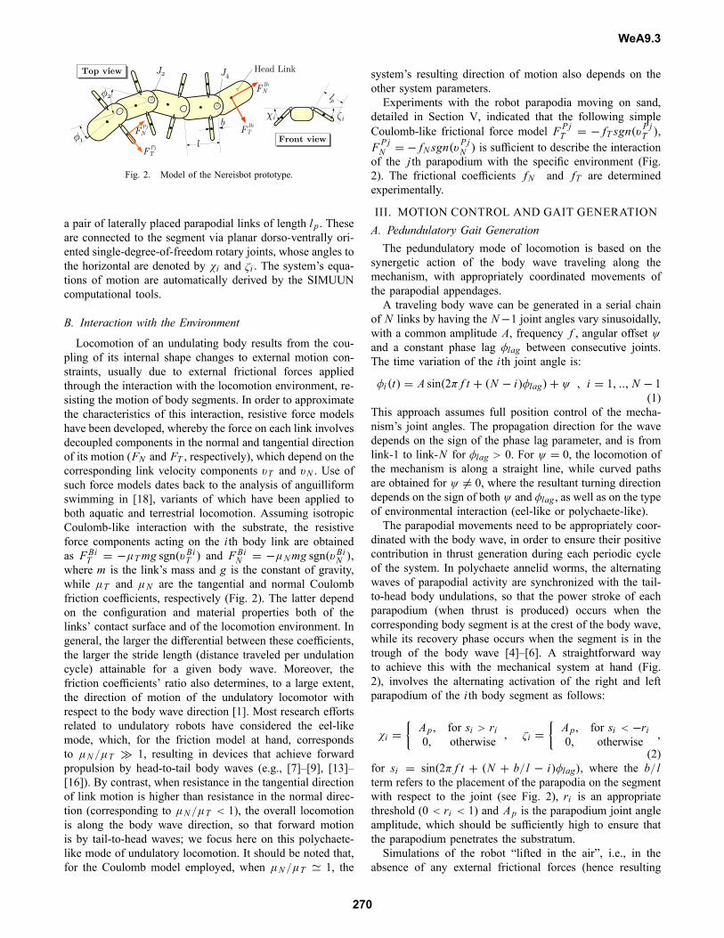
A = 30◦, Ap = 20◦, ri = 0.2z
(mm
)
Fig. 3. Trajectories traced by the tips of all the parapodia in the Nereisbotmodel during a cycle of in-place pedundulation of the system. The partof the traces shown in red indicates the power stroke of the parapodia,when they are in contact with the substrate. The blue and cyan lines denoterespectively the x− and y−components of the parapodium velocity duringthe power stroke, indicating that the velocity is mostly directed towards thetail. The trajectories of the four body joints are also shown on the graph.
in in-place pedundulations of the system, without any netmovement), indicate that the adopted control law (2) for theparapodia, when used in conjunction with a tail-to-head bodywave (1), ensures that the parapodia move backwards relativeto the substrate during their power stroke. Therefore, theircontribution in thrust generation is, in general, positive whenthey are in contact with the ground (Fig. 3).The parapodia provide a number of alternatives for in-
stigating turning motions in pedundulatory systems. Morespecifically, the methods identified here are: (a) by introduc-ing an angular offset ψ = 0 in the body wave (1), while theparapodia operate in the bilateral fashion described by (2),(b) by unilateral parapodial activations, while ψ = 0, and(c) by combining a non-zero angular offset with unilateralparapodial activation. The “unilateral” parapodial activationin these methods implies disabling all parapodial movementin the appropriate side of the mechanism, depending on thedesired turning direction.
B. Simulation Studies of Pedundulatory GaitsThis section presents a series of SIMUUN simulations
of the Nereisbot prototype, demonstrating pedundulatorylocomotion by implementing the motion control strategies ofthe previous Section. The mechanical parameters (masses,dimensions, etc.) of the Nereisbot model developed inSIMUUN reflect those of the actual prototype. Appropriatefrictional force measurements with the robot are used toselect a plausible force model, for simulating the interactionof the body segments and of the parapodia, with the loco-motion environment. This procedure is detailed in SectionV, for experiments over fine sand, where the parameters ofthe models of Section II-B, are specified. In the simulationspresented, Coulomb friction is used to model the interaction
0 50 100 150 200 250 300 350 400
−100
−50
0
x (mm)
y (m
m)
Trajectory of tail joint J1
f = 1Hz, A = 30◦
undulatory mode (inactive parapodia)pedundulatory mode (active parapodia)
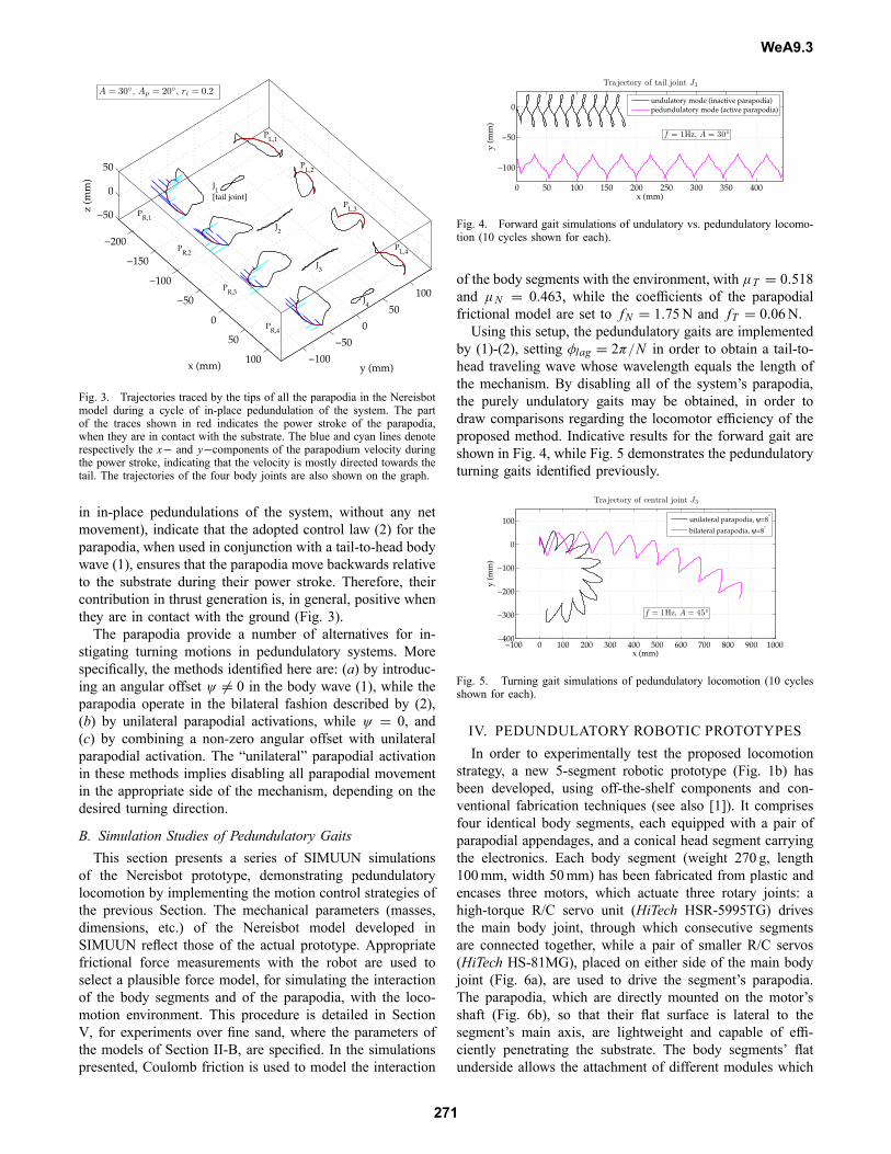
Fig. 4. Forward gait simulations of undulatory vs. pedundulatory locomo-tion (10 cycles shown for each).
of the body segments with the environment, with μT = 0.518and μN = 0.463, while the coefficients of the parapodialfrictional model are set to fN = 1.75N and fT = 0.06N.Using this setup, the pedundulatory gaits are implemented
by (1)-(2), setting φlag = 2π/N in order to obtain a tail-to-head traveling wave whose wavelength equals the length ofthe mechanism. By disabling all of the system’s parapodia,the purely undulatory gaits may be obtained, in order todraw comparisons regarding the locomotor efficiency of theproposed method. Indicative results for the forward gait areshown in Fig. 4, while Fig. 5 demonstrates the pedundulatoryturning gaits identified previously.
−100 0 100 200 300 400 500 600 700 800 900 1000−400
−300
−200
−100
0
100
x (mm)
y (m
m)Trajectory of central joint J3
f = 1Hz, A = 45◦
unilateral parapodia, ψ=8°
bilateral parapodia, ψ=8°
Fig. 5. Turning gait simulations of pedundulatory locomotion (10 cyclesshown for each).
IV. PEDUNDULATORY ROBOTIC PROTOTYPESIn order to experimentally test the proposed locomotion
strategy, a new 5-segment robotic prototype (Fig. 1b) hasbeen developed, using off-the-shelf components and con-ventional fabrication techniques (see also [1]). It comprisesfour identical body segments, each equipped with a pair ofparapodial appendages, and a conical head segment carryingthe electronics. Each body segment (weight 270 g, length100mm, width 50mm) has been fabricated from plastic andencases three motors, which actuate three rotary joints: ahigh-torque R/C servo unit (HiTech HSR-5995TG) drivesthe main body joint, through which consecutive segmentsare connected together, while a pair of smaller R/C servos(HiTech HS-81MG), placed on either side of the main bodyjoint (Fig. 6a), are used to drive the segment’s parapodia.The parapodia, which are directly mounted on the motor’sshaft (Fig. 6b), so that their flat surface is lateral to thesegment’s main axis, are lightweight and capable of effi-ciently penetrating the substrate. The body segments’ flatunderside allows the attachment of different modules which
WeA9.3
271

(a) (b) (c)
Fig. 6. Components of the Nereisbot prototype: (a) placement of the servomotors inside the body segments. (b) The instrumented parapodium, shownmounted on its motor. (c) The underside of a body segment, shown withtwo sets of longitudinally mounted blades.
implement the interaction with the locomotion environment,by providing differential friction in the tangential and normaldirections of motion. For movement over relatively smoothsurfaces, wheeled modules can be used. For movement overunstructured environments, such as sand, special moduleshave been developed (Fig. 6c), which employ aluminumblades whose number, spacing and orientation can be easilyaltered. The head segment has been shaped as a cone toaid the advancement through unstructured substrates, andcarries the batteries powering the robot, as well as theon-board microcontroller unit (Motorola DSP56807), whichgenerates all the control signals for the motors implementingthe pedundulatory movements. Space restrictions prohibitedfitting parapodia on this segment.In addition, a special instrumented parapodium unit has
been developed (Fig. 6b), which incorporates a set of fourstrain gauges (Showa N11-MA2-120-11) in a Wheatstone-bridge setup, appropriately configured to measure the normalcomponent FPjN of the force generated by the parapodium.The characteristic of the sensor was found, via calibrationtests, to be linear in the operational range of interest.This robotic prototype is versatile enough to allow the
experimental study, not only of polychaete-like gaits, but ofother, very different, pedundulatory gaits as well.
V. EXPERIMENTS ON SAND
Experimental results from tests, with the Nereisbot pro-totype moving over sand, are presented here and comparedwith the corresponding SIMUUN simulation results. Initialexperiments (presented in Section V-A below) implementpurely undulatory gaits by disabling all parapodial activity.This provides a comparative measure for evaluating theperformance gains obtained by the pedundulatory mode.Experiments with the latter mode are presented in SectionV-B.Experimental setup: The prototype was placed inside abox (measuring 1.7m x 1.7m), which was uniformly filledwith 35mm of fine seashore sand (mean particle diameter:0.6mm). The experiments were conducted over a range ofvalues for A (20◦ − 60◦), with f = 1Hz, and for twodifferent configurations of the body segments’ underside: (i)without blades, and (ii) with a total of four transversallymounted blades. A pair of colored markers was mounted ontop of the tail (J1) and central (J3) joints of the mechanism.
TABLE IFRICTION FORCE COEFFICIENTS.
μT μN μT /μNWithout blades 0.518 0.463 1.111
Transversally mounted blades 0.852 0.741 1.150Longitudinally mounted blades 0.741 0.926 0.800
These allowed the reconstruction of the respective joints’trajectories, via post-processing of the experiment videos.In order to assess the developed computational models,
corresponding simulations were carried out in SIMUUN,replicating for each experimental run the set of parametersused, and incorporating the frictional data below.Frictional force measurements: In order to select an appro-priate force model for the simulations, special measurementswere performed to obtain data on the frictional characteristicsof the mechanism, with respect to the configuration of thesegments’ underside (i.e., with or without blades) and thespecific locomotion substrate. The forces required to movea single body segment over sand, in both the tangentialand normal directions with respect to its main axis, weremeasured using a load cell. Much like the corresponding testsin [1], the interaction forces presented little variance in therange of traction velocities tested, indicating that a simpleCoulomb friction model could be used for the interactionof the body with the sand environment. The resultant setsof Coulomb friction coefficients (summarized in Table I)indicate that, for the no-blade configuration, the resistance inthe tangential direction is slightly higher than in the normaldirection. The use of blades, despite significantly increasingthe magnitude of the interaction forces (i.e., the resistanceof the mechanism to motion), achieves only small increasesin the friction differential μT /μN .Due to their shape (cf. Fig. 6b) and movement, the tan-
gential force component FPjT of the parapodia is negligiblewith respect to the normal one FPjN . A series of tests wasperformed with the instrumented parapodium mounted on thetail link of the mechanism, for the no-blades configuration.The measurements indicate that, for the specific parametersconsidered in (2), the movement of the parapodia is properlycoordinated with the body wave, so that the forces impartedthroughout the power stroke of each pedundulation cycle arepositive (i.e., contributing to thrust generation). The averagegenerated normal forces during the power stroke, for the
0 1 2 3 4
0
1
2
3
Time (sec)
A = 60◦
0 1 2 3 4
0
1
2
3
Time (sec)
Forc
e (N
)
A = 45◦
Fig. 7. Measurements of the normal force generated by the instrumentedparapodium, placed at the mechanism’s tail segment, during pedundulatorylocomotion.
WeA9.3
272
10 cm
(a) no-blade configuration, A=60◦
10 cm
(b) transversal-blades configuration, A=60◦
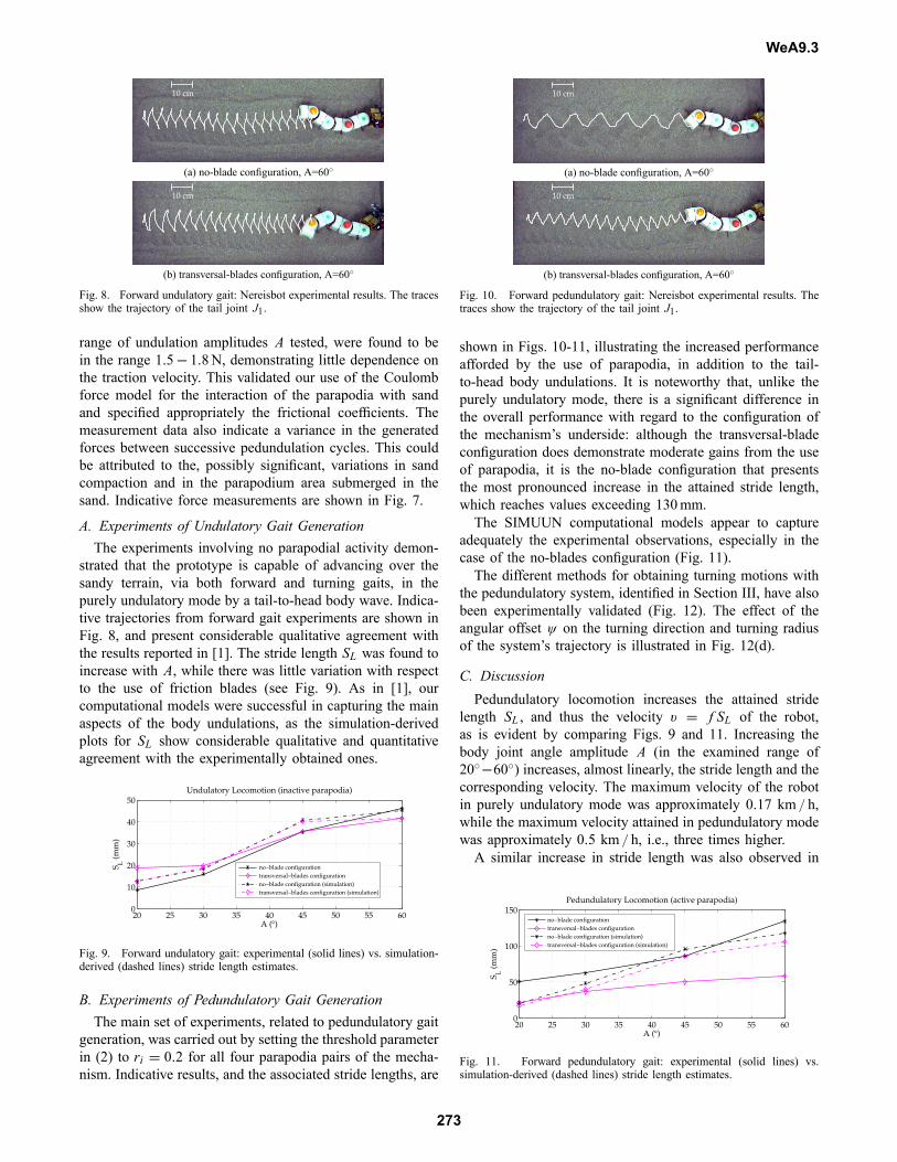
Fig. 8. Forward undulatory gait: Nereisbot experimental results. The tracesshow the trajectory of the tail joint J1.
range of undulation amplitudes A tested, were found to bein the range 1.5− 1.8N, demonstrating little dependence onthe traction velocity. This validated our use of the Coulombforce model for the interaction of the parapodia with sandand specified appropriately the frictional coefficients. Themeasurement data also indicate a variance in the generatedforces between successive pedundulation cycles. This couldbe attributed to the, possibly significant, variations in sandcompaction and in the parapodium area submerged in thesand. Indicative force measurements are shown in Fig. 7.
A. Experiments of Undulatory Gait GenerationThe experiments involving no parapodial activity demon-
strated that the prototype is capable of advancing over thesandy terrain, via both forward and turning gaits, in thepurely undulatory mode by a tail-to-head body wave. Indica-tive trajectories from forward gait experiments are shown inFig. 8, and present considerable qualitative agreement withthe results reported in [1]. The stride length SL was found toincrease with A, while there was little variation with respectto the use of friction blades (see Fig. 9). As in [1], ourcomputational models were successful in capturing the mainaspects of the body undulations, as the simulation-derivedplots for SL show considerable qualitative and quantitativeagreement with the experimentally obtained ones.
20 25 30 35 40 45 50 55 600
10
20
30
40
50
A (°)
S L (m
m)
Undulatory Locomotion (inactive parapodia)
no−blade configurationtransversal−blades configurationno−blade configuration (simulation)transversal−blades configuration (simulation)
Fig. 9. Forward undulatory gait: experimental (solid lines) vs. simulation-derived (dashed lines) stride length estimates.
B. Experiments of Pedundulatory Gait GenerationThe main set of experiments, related to pedundulatory gait
generation, was carried out by setting the threshold parameterin (2) to ri = 0.2 for all four parapodia pairs of the mecha-nism. Indicative results, and the associated stride lengths, are
10 cm
(a) no-blade configuration, A=60◦
10 cm
(b) transversal-blades configuration, A=60◦
Fig. 10. Forward pedundulatory gait: Nereisbot experimental results. Thetraces show the trajectory of the tail joint J1.
shown in Figs. 10-11, illustrating the increased performanceafforded by the use of parapodia, in addition to the tail-to-head body undulations. It is noteworthy that, unlike thepurely undulatory mode, there is a significant difference inthe overall performance with regard to the configuration ofthe mechanism’s underside: although the transversal-bladeconfiguration does demonstrate moderate gains from the useof parapodia, it is the no-blade configuration that presentsthe most pronounced increase in the attained stride length,which reaches values exceeding 130mm.The SIMUUN computational models appear to capture
adequately the experimental observations, especially in thecase of the no-blades configuration (Fig. 11).The different methods for obtaining turning motions with
the pedundulatory system, identified in Section III, have alsobeen experimentally validated (Fig. 12). The effect of theangular offset ψ on the turning direction and turning radiusof the system’s trajectory is illustrated in Fig. 12(d).
C. DiscussionPedundulatory locomotion increases the attained stride
length SL , and thus the velocity v = f SL of the robot,as is evident by comparing Figs. 9 and 11. Increasing thebody joint angle amplitude A (in the examined range of20◦−60◦) increases, almost linearly, the stride length and thecorresponding velocity. The maximum velocity of the robotin purely undulatory mode was approximately 0.17 km / h,while the maximum velocity attained in pedundulatory modewas approximately 0.5 km / h, i.e., three times higher.A similar increase in stride length was also observed in
20 25 30 35 40 45 50 55 600
50
100
150
A (°)
S L (m
m)
Pedundulatory Locomotion (active parapodia)
no−blade configurationtransversal−blades configurationno−blade configuration (simulation)transversal−blades configuration (simulation)
Fig. 11. Forward pedundulatory gait: experimental (solid lines) vs.simulation-derived (dashed lines) stride length estimates.
WeA9.3
273
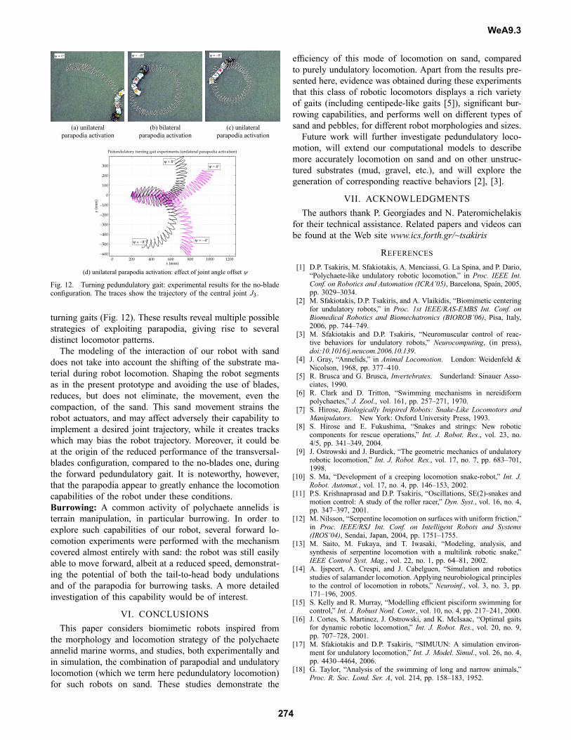
ψ = 0° ψ = −8° ψ = −8°
(a) unilateral (b) bilateral (c) unilateralparapodia activation parapodia activation parapodia activation
0 200 400 600 800 1000 1200−600
−500
−400
−300
−200
−100
0
100
200
300 ψ = 4°ψ = 8°
ψ = −4°ψ = −8°
x (mm)
y (m
m)
Pedundulatory turning gait experiments (unilateral parapodia activation)
(d) unilateral parapodia activation: effect of joint angle offset ψ
Fig. 12. Turning pedundulatory gait: experimental results for the no-bladeconfiguration. The traces show the trajectory of the central joint J3.
turning gaits (Fig. 12). These results reveal multiple possiblestrategies of exploiting parapodia, giving rise to severaldistinct locomotor patterns.The modeling of the interaction of our robot with sand
does not take into account the shifting of the substrate ma-terial during robot locomotion. Shaping the robot segmentsas in the present prototype and avoiding the use of blades,reduces, but does not eliminate, the movement, even thecompaction, of the sand. This sand movement strains therobot actuators, and may affect adversely their capability toimplement a desired joint trajectory, while it creates trackswhich may bias the robot trajectory. Moreover, it could beat the origin of the reduced performance of the transversal-blades configuration, compared to the no-blades one, duringthe forward pedundulatory gait. It is noteworthy, however,that the parapodia appear to greatly enhance the locomotioncapabilities of the robot under these conditions.Burrowing: A common activity of polychaete annelids isterrain manipulation, in particular burrowing. In order toexplore such capabilities of our robot, several forward lo-comotion experiments were performed with the mechanismcovered almost entirely with sand: the robot was still easilyable to move forward, albeit at a reduced speed, demonstrat-ing the potential of both the tail-to-head body undulationsand of the parapodia for burrowing tasks. A more detailedinvestigation of this capability would be of interest.
VI. CONCLUSIONSThis paper considers biomimetic robots inspired from
the morphology and locomotion strategy of the polychaeteannelid marine worms, and studies, both experimentally andin simulation, the combination of parapodial and undulatorylocomotion (which we term here pedundulatory locomotion)for such robots on sand. These studies demonstrate the
efficiency of this mode of locomotion on sand, comparedto purely undulatory locomotion. Apart from the results pre-sented here, evidence was obtained during these experimentsthat this class of robotic locomotors displays a rich varietyof gaits (including centipede-like gaits [5]), significant bur-rowing capabilities, and performs well on different types ofsand and pebbles, for different robot morphologies and sizes.Future work will further investigate pedundulatory loco-
motion, will extend our computational models to describemore accurately locomotion on sand and on other unstruc-tured substrates (mud, gravel, etc.), and will explore thegeneration of corresponding reactive behaviors [2], [3].
VII. ACKNOWLEDGMENTSThe authors thank P. Georgiades and N. Pateromichelakis
for their technical assistance. Related papers and videos canbe found at the Web site www.ics.forth.gr/~tsakiris
REFERENCES[1] D.P. Tsakiris, M. Sfakiotakis, A. Menciassi, G. La Spina, and P. Dario,
“Polychaete-like undulatory robotic locomotion,” in Proc. IEEE Int.Conf. on Robotics and Automation (ICRA’05), Barcelona, Spain, 2005,pp. 3029–3034.
[2] M. Sfakiotakis, D.P. Tsakiris, and A. Vlaikidis, “Biomimetic centeringfor undulatory robots,” in Proc. 1st IEEE/RAS-EMBS Int. Conf. onBiomedical Robotics and Biomechatronics (BIOROB’06), Pisa, Italy,2006, pp. 744–749.
[3] M. Sfakiotakis and D.P. Tsakiris, “Neuromuscular control of reac-tive behaviors for undulatory robots,” Neurocomputing, (in press),doi:10.1016/j.neucom.2006.10.139.
[4] J. Gray, “Annelids,” in Animal Locomotion. London: Weidenfeld &Nicolson, 1968, pp. 377–410.
[5] R. Brusca and G. Brusca, Invertebrates. Sunderland: Sinauer Asso-ciates, 1990.
[6] R. Clark and D. Tritton, “Swimming mechanisms in nereidiformpolychaetes,” J. Zool., vol. 161, pp. 257–271, 1970.
[7] S. Hirose, Biologically Inspired Robots: Snake-Like Locomotors andManipulators. New York: Oxford University Press, 1993.
[8] S. Hirose and E. Fukushima, “Snakes and strings: New roboticcomponents for rescue operations,” Int. J. Robot. Res., vol. 23, no.4/5, pp. 341–349, 2004.
[9] J. Ostrowski and J. Burdick, “The geometric mechanics of undulatoryrobotic locomotion,” Int. J. Robot. Res., vol. 17, no. 7, pp. 683–701,1998.
[10] S. Ma, “Development of a creeping locomotion snake-robot,” Int. J.Robot. Automat., vol. 17, no. 4, pp. 146–153, 2002.
[11] P.S. Krishnaprasad and D.P. Tsakiris, “Oscillations, SE(2)-snakes andmotion control: A study of the roller racer,” Dyn. Syst., vol. 16, no. 4,pp. 347–397, 2001.
[12] M. Nilsson, “Serpentine locomotion on surfaces with uniform friction,”in Proc. IEEE/RSJ Int. Conf. on Intelligent Robots and Systems(IROS’04), Sendai, Japan, 2004, pp. 1751–1755.
[13] M. Saito, M. Fukaya, and T. Iwasaki, “Modeling, analysis, andsynthesis of serpentine locomotion with a multilink robotic snake,”IEEE Control Syst. Mag., vol. 22, no. 1, pp. 64–81, 2002.
[14] A. Ijspeert, A. Crespi, and J. Cabelguen, “Simulation and roboticsstudies of salamander locomotion. Applying neurobiological principlesto the control of locomotion in robots,” Neuroinf., vol. 3, no. 3, pp.171–196, 2005.
[15] S. Kelly and R. Murray, “Modelling efficient pisciform swimming forcontrol,” Int. J. Robust Nonl. Contr., vol. 10, no. 4, pp. 217–241, 2000.
[16] J. Cortes, S. Martinez, J. Ostrowski, and K. McIsaac, “Optimal gaitsfor dynamic robotic locomotion,” Int. J. Robot. Res., vol. 20, no. 9,pp. 707–728, 2001.
[17] M. Sfakiotakis and D.P. Tsakiris, “SIMUUN: A simulation environ-ment for undulatory locomotion,” Int. J. Model. Simul., vol. 26, no. 4,pp. 4430–4464, 2006.
[18] G. Taylor, “Analysis of the swimming of long and narrow animals,”Proc. R. Soc. Lond. Ser. A, vol. 214, pp. 158–183, 1952.
WeA9.3
274