Embed Size (px)
Citation preview

Polymer and Hybrid Capacitor Product Overview

Capacitor Selection
Capacitors selection, to the uninformed, seems like a simple choice.
But the demands, challenges and expectations of modern electronics prove otherwise.
Design Engineers have many considerations when choosing the right capacitor for the job.
Electrical Characteristics Stability Life and reliability Safety Cost
Many conventional capacitor technologies offer strong value propositions while no longer meeting the demands of today’s challenging designs.

The Solution …
Advanced Polymer Capacitors from Panasonic provide solutions to these challenges.

Why Switch to Polymer Technology?
Requirements and challenges of high performance miniaturized modern electronic design combined with expectations of high reliability and long life Conventional capacitors are not up to the challenge Advanced Polymer capacitors provide higher performance in a reduced footprint while offering longer life and improved reliability!

Polymer Capacitor Advantages
Polymer capacitors offer distinctive advantages over conventional capacitors in these specific areas:
Stability Life Reliability Safety Component Reduction

Capacitance Stability
Conventional Electrolytic and MLCCs suffer from capacitance drifts of up to 90% in response to temperature and DC bias.
Polymer Capacitors have no such problem.

Versus MLCC
-90
-80
-70
-60
-50
-40
-30
-20
-10
0
10
0 1 2 3 4 5 6 7
DC Bias (V)
dC /
C (%
)
-30
-20
-10
0
10
20
-55 -35 -15 5 25 45 65 85 105
Temp. ()
⊿C
/C (%
)
MLCCMLCC
MLCC:6.3V47uF/3216/X5R
POSCAP/SP-Cap/OS-CON:6.3V47uF
DC biased characteristic Temperature characteristic
POSCAP/SP-Cap/OS-CON are stable under actual use condition. (Temperature and DC Bias)
HybridStability

Life

Reliability

Over Voltage Test:The test capacitors were made to short purposely.Smoke and ignition were checked by the constant current examination.
1A
3A
5A 7A
5A
3A
General tantalum (MnO2 type)
This data is an experimental example. A numerical value and a phenomenon are not guaranteed.
SP-Cap vs. Tantalum Cap
Benign failure mode vs. catastrophic failure of tantalum cap (MnO2)
Applied Voltage :30V.DC, Limit current :6A max
General tantalum(MnO2 type)
POSCAP vs. Tantalum Cap
Safety

OpenOpenOpenOpenLife EndFailure Modes
4600 mA / 100 kHz, 105 4400 mA / 100 kHz, 105 3000 mA / 100 kHz, 105 3200 mA / 100 kHz, 105 Total Ripple
20 % (100 mm2)100 % (491 mm2)13 % (62 mm2)100 % (491 mm2)
Mounting Area
105 , 10,000 h105 , 5,000 h105 , 10,000 h105 , 5,000 hEndurance
13.5 m / 100 kHz15 m / 100 kHz40 m / 100 kHz40 m / 100 kHzTotal ESR
Index: 0.5
6.3×7.7 / DC 63 V / 22 F× 2 pcs.
Hybrid type Al. Electrolytic
Index: 1
12.5×13.5 / 63 V / 220 F× 4 pcs.
Al. Electrolytic
DC 48V Line Solution
Index: 0.58Index: 1Total Cost
8.0×10.2 / DC 35 V / 150 F× 2 pcs.
12.5×13.5 / 35 V / 680 F× 4 pcs.Item
Hybrid type Al. ElectrolyticAl. ElectrolyticCapacitors
DC 24V Line Solution
Replacement Proposal
Aluminum Electrolytic Capacitors(SMD)
12.513.5 mm / 63 V / 220 uF 4 pcs.
12.513.5 mm / 35 V / 680 uF 4 pcs.
You can achieve high performanceand miniaturization of equipmentby adopting Hybrid Capacitor!!
You can achieve high performanceand miniaturization of equipmentby adopting Hybrid Capacitor!!
DC 48 V
TRX PA DUPBase Band
AC/DC
DC/DC DC/DCDC 24 V
Component Reduction

Panasonic Polymer CapacitorPanasonic has four Polymer Capacitor alternatives, each with distinct sweet spots that can address ideal voltages, frequency characteristics, environmental conditions and other application requirements that are challenging for conventional capacitors.
• SP‐Cap®– Layered Polymer Aluminum Capacitors
• POSCAP®– Polymer Tantalum Capacitors
• Hybrid– Polymer Hybrid Aluminum Capacitors
• OS‐CON®–Wound Polymer Aluminum Capacitors
Panasonic Polymer CapacitorSP-Cap®
Layered Polymer Aluminum Capacitor – polymer is used as the electrolyte with an aluminum cathode. SP-Caps are packaged in a molded resin surface mount package.
SP-Caps are available with a voltage rating from 2 to 25V and capacitance of 2.2 to 560uF. The distinguishing electrical characteristic of these polymer capacitors is their extremely low equivalent series resistance (ESR) as low as 3mΩ

Panasonic Polymer CapacitorsPOSCAP®
Polymer Tantalum Capacitors employ a polymer as the electrolyte and have a tantalum cathode. Packaged in a molded resin case, the tantalum polymer capacitors are among the most compact on the market. The M size measures just 1.6 by 0.8 mm.
POSCAP capacitors are available with a voltage rating from 1.8 to 35V and capacitances from 2.7 to 680µFThey, too, have low ESR values as low as 5mΩ.

Panasonic Polymer CapacitorsOS-CON®
Wound Polymer Aluminum Capacitors utilize conductive polymer as the electrolyte and wound aluminum as the cathode. The polymer electrolyte yields very low ESR (below 5mΩ) while the wound aluminum cathode provides a large surface area enabling high capacitance.
OS-CON Capacitors are available in a voltage range of 2 to 50 VDC and capacitances from 3.3 to 2700µF.

Life Formula – POSCAP & OS-CON

Panasonic Polymer Capacitor
PANASONIC HYBRIDPolymer Hybrid Aluminum Capacitors use a combination of a liquid and polymer to serve as the electrolyte and aluminum as the cathode. This combination attains the best of polymer and electrolytic capacitor technology; low ESR of a polymer (20 to 120mΩ) along with high voltages and higher capacitance of an electrolytic.
Hybrid capacitors are available in a voltage range of 25 to 80V and capacitances between 10 and 330µF.
30
40
50
60
70
80
90
100
110
2000 100000 200000(h)
Am
bien
t Tem
pera
ture
(ºC
)
5000020000100005000
Years
24hoperation 207 101 2 3 4 5
85C 1000h
85C 2000h
105C1000h
105C2000h
105C3000h
105C5000h
105C10000h
20 303 6 10 15
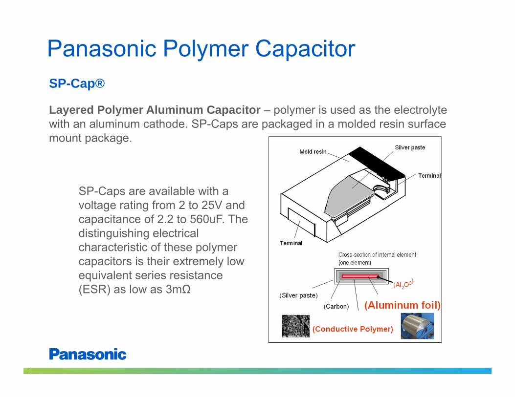
Aluminum Capacitor Life Calculation
Every -10ºC, x 2 life
Years8h Op.
Liquid electrolyte Dry-up Open Failure Finite Life

Choosing the Right Polymer Capacitor
OS‐CON and Hybrid vs. Lytic POSCAP and SP‐Caps vs. Ceramic and/or Tantalum

OS-CON and HybridKey difference with Standard Aluminum Capacitor Ultra Low ESR, Low impedance (as low 1/100 of a typical lytic) Higher ripple current capability (upwards of 3~5 times) Stable characteristics, longer life time (up to 15 years in case of OS‐CON)

POSCAP and SP-CapKey with Standard Tantalum Capacitor and MLCC Ultra Low ESR, Low impedance (as low as 1/100) High reliability (does not explode like a Tantalum) SP‐Cap: no derating. No Piezo effect for both POSCAP and SP‐Cap (unlike MLCC)

22
MLCC POSCAP
Benefit
AntiNoise MLCC POSCAP x 1pcs
25V 10uF x 8 pcs
1. Cost 50%off
2. Space 80% off
3. Same Capacitance
Large current power supply circuit
25TQC15MYFB
Actual Cap. Approx. 15uF(3.5 x 1.7) x 8 pcs = 48mm2 (3.5 x 2.8) x 1 pcs = 9.8mm2
size 3517
Actual Cap.25V 15uFMurata:KMR31FR61E106KH01K
MLCC SP‐Cap
Benefit
High Voltage MLCC SP‐Cap x 1pcsSize 3225
27uF x 5 pcs
1. Cost 30%off
2. Space 25% off
Large current DC/DC or LSI
EEFSX0D471E4EEFLXoD471R4
Actual Cap. 1.5V 470uF
(7.3 x 4.3) x 1 pcs = 31mm2
Condition
Condition
Replacement from MLCC to POSCAP/SP‐Cap

23
MLCC OS‐CON
BENEFIT
High Voltage MLCC
OS‐CON x 1pcs
100V 22uF x 4 pcs
1. Cost 70~80%off
2. Space ‐47%~58% off
3. Same Capacitance
High voltage & Large current power supply circuit
100SXV15M63SXV33M
Actual Cap.
100V 15uF63V 33uF
Actual Cap. Approx. 15uF(6.1 x 5.3) x 4 pcs = 129mm2
(8.3 x 8.3) x 1 pcs = 69mm2
size 5750
50V 22uF x 5 pcssize 5750
TDK:CKG57NX7S2A226M500JH
TDK:CKG57NX7S1H226M500JHMurata:KRM55WR71H226MH01K
Condition
Replacement from MLCC to OS‐CON

24
MLCC + E‐CAP Hybrid
BENEFIT
High Voltage MLCC +
Radial E‐CAP
Hybrid‐Cap x1pcs
1. Space ‐58% off
2. Same Capacitance
3. Low ESR/High ripple
High voltage & Large current power supply circuit
EEHZC1E221P
25V 220uF x 1 pcssize φ10x12.5mm
Mount Area = 110mm2
Condition
100V 22uF x 4 pcssize 5750
+
Mount Area = 69mm2
size φ8x10.2mm
ESR = 20mΩRipple= 1600mA
ESR = 110mΩRipple= 680mA
Replacement from MLCC + Radial AL to Hybrid

Polymer and Hybrid Capacitor Product Overview
Thank You!