Embed Size (px)
Citation preview
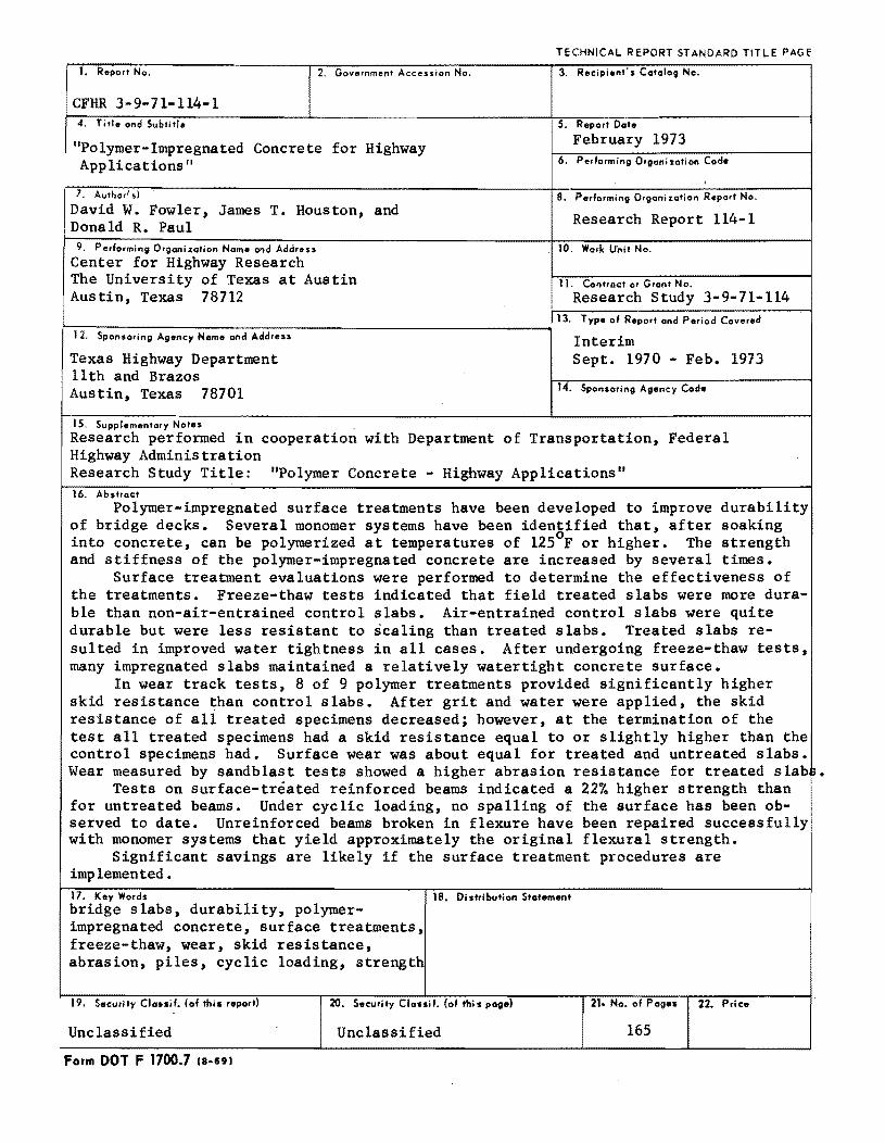
1. Report No. 2, Government Accession No.
CFHR 3-9-71-114-1 4. Title and Subtitle
"Polymer-Impregnated Concrete for Highway Applications"
7. Authorf,)
David W. Fowler, James T. Houston, and Donald R. Paul
9. Perlorming Orgonizolion Nome end Address
Center for Highway Research The University of Texas at Austin Austin, Texas 78712
~~~--------~--~~--------------------------~ 12. Sponsoring Agency Norne and Addre ..
Texas Highway Department 11th and Brazos Austin, Texas 78701
15. Supplementary Notes
TECHNICAL REPORT STANDARD TITLE PAGE
3. Recipient's Catalog No.
5. Reporl Dale
February 1973 6. Performing Organ; zolion Code
B. Performing Organization Reporl No.
Research Report 114-1
10. Work Unit No.
11. Contract or Grant No.
Research Study 3-9-71-114 13. Type 01 Report and Period Covered
Interim Sept. 1970 - Feb. 1973
14. Sponsoring Agency Code
Research performed in cooperation with Department of Transportation, Federal Highway Administration Research Study Title: "Polymer Concrete - Highway Applications" 16. Abstract
Polymer-impregnated surface treatments have been developed to improve durability of bridge decks. Several monomer systems have been identified that, after soaking into concrete, can be polymerized at temperatures of l250 F or higher. The strength and stiffness of the polymer-impregnated concrete are increased by several times.
Surface treatment evaluations were performed to determine the effectiveness of the treatments. Freeze-thaw tests indicated that field treated slabs were more durable than non-air-entrained control slabs. Air-entrained control slabs were quite durable but were less resistant to scaling than treated slabs. Treated slabs resulted in improved water tightness in all cases. After undergoing freeze-thaw tests, many impregnated slabs maintained a relatively watertight concrete surface.
In wear track tests, 8 of 9 polymer treatments provided Significantly higher skid resistance than control slabs. After grit and water were applied, the skid resistance of all treated specimens decreased; however, at the termination of the test all treated specimens had a skid resistance equal to or slightly higher than the control specimens had. Surface wear was about equal for treated and untreated slabs. Wear measured by sandblast tests showed a higher abrasion resistance for treated slab~
Tests on surface-treated reinforced beams indicated a 22% higher strength than for untreated beams. Under cyclic loading, no spalling of the surface has been observed to date. Unreinforced beams broken in flexure have been repaired successfully with monomer systems that yield approximately the original flexural strength.
Significant savings are likely if the surface treatment procedures are implemented. 17. Key Words lB. Distribution Statement bridge slabs, durability~ polymer-impregnated concrete, surface treatments, freeze-thaw, wear, skid reSistance, abrasion, piles, cyclic loading, strength
19. Security Clauil. (01 thi. report) 20. Security Classil. (01 this page) 21. No. 01 Pag.. 22. Price
! Unclassified Unclassified 165
Form DOT F 1700.7 (B-691
POLYMER-IMPREGNATED CONCRETE FOR HIGHWAY APPLICATIONS
by
David W. Fowler James T. Houston
Donald R. Paul
Research Report Number 114-1
Research Project 3-9-71-114
conducted for
The Texas Highway Department
in cooperation with the U. S. Department of Transportation
Federal Highway Administration
by the
CENTER FOR HIGHWAY RESEARCH THE UNIVERSITY OF TEXAS AT AUSTIN
February 1973

The contents of this report reflect the views of the authors I who are responsible for the facts and the accuracy of the data presented herein. The contents do not necessarily reflect the official views or policies of the Federal Highway Administration. This report does not consti tute a standard I specification, or regulation.
Ii
PREFACE
The research on "Polymer-Impregnated Concrete for Highway Appli
cations II began September I, 1970, and is in the third year. This is the
first formal report issued on the research and summarizes the results of
the study through the first two and one-half years.
Polymer-impregnated concrete was developed less than ten years
ago: the first public mention was about five years ago. When this study
began, nearly all related research had been conducted in laboratories
under idealized conditions. Concrete had been fully impregnated using
an initial vacuum, immersion in monomer baths I and curing by either
cobalt- 60 irradiation or elevated temperatures. These techniques were
simply not adequate for large scale use in treating the surfaces of bridges.
But the excellent improvement in strength and durability properties made
the effort to develop practical surface treatments worthwhile.
While the purpose of this investigation was to determine if polymer
impregnated surface treatments were effective in improving durability, the
major problem was in developing practical surface treatments. The
obstacles encountered have been numerous and challenging, but with the
dedicated help of graduate research assistants Jimmie Henze, Michael
-11i-
McNeil, Ragan Broyles, and John Wyman, and the fine work of Robert
Garcia, project technician, practical surface treatment techniques have
been developed that have proven to be effective in improving slab dura
bility. Significant savings should result from the expected implementa
tion of these findings. Many other applications of polymer-impregnated
concrete for highway uses also appear probable.
The project would never have been initiated, however, without the
vision , faith and support of the Texas Highway Department and the Fed
eral Highway Administration. The continued patience I encouragement,
and helpful suggestions of these agencies have been greatly appreciated.
In particular the study supervisors are indebted to Donald 0 'Connor and
M. U. Ferrari , contact representatives of the Texas Highway Department,
and Jerry Bowman and Robert Pike of the Federal Highway Administration.
February 1973
iv
David W. Fowler
James T. Houston
Donald R. Paul
ABSTRACT
Polymer-impregnated surface treatments have been developed to
improve durability of bridge decks. Several monomer systems have been
identified that, after soaking into concrete I can be polymerized at tem
peratures of 12 SOF or higher. Several methods of obtaining the required
temperature are available. The strength and stiffness of the polymer
impregnated concrete are increased by several times.
Surface treatment evaluations were performed to determine the
effectiveness of the treatments. Freeze-thaw tests indicated that field
treated slabs were more durable than non-air-entrained control slabs.
Air-entrained control slabs were quite durable but were less resistant to
scaling than treated slabs. Treated slabs resulted in improved water
tightness in all cases. After undergoing freeze-thaw tests, many impreg
nated slabs maintained a relatively watertight concrete surface.
In wear track tests, 8 of 9 polymer treatments provided significantly
higher skid resistance than control slabs after 140, 000 wheel passes.
After grit and water were applied I the skid resistance of all treated speci
mens decreased; however, at the termination of the tes t (42 0, 000 wheel
passes) all treated specimens had a skid resistance equal to or slightly
v
higher than the control specimens had. Surface wear was approximately
equal for treated and untreated slabs. Wear measured by sandblast tests
indicated a higher abrasion resistance for treated slabs.
Tests on surface-treated reinforced beams indicated a 22 percent
higher strength than for untreated beams. Under cyclic loading, no
spalling of the surface has been observed to date.
Unreinforced beams broken in flexure have been repaired success
fully with several monomer systems that yield approximately the original
flexural strength.
The estimated total cost of surface treatments for bridge decks
ranges from $0.40 to $0.90/sq ft. Significant savings are likely if the
surface treatment procedures are implemented.
KEY WORDS: bridge slabs, durability, polymer-impregnated concrete,
surface treatments, freeze-thaw, wear, skid resistance, abrasion, piles,
cyclic loading, strength.
vi
SUMMARY
The use of polymer-impregnated concrete for highway applications
has been investigated. The primary research effort has been focused on
the development of practical surface treatments for highway bridge decks
to increase the durability. Several liquid plastics, called monomers,
have been identified as being suitable for this purpose. A quarter-inch
layer of sand on the surface of the concrete is sprayed with the monomer
and it is allowed to soak into the concrete for 8 to 10 hours. The sand
serves the purpose of holding the monomer on sloped bridge decks and
minimizing the run-off. The 8 to 10-hour soaking interval is required to
allow the monomer to fill the minute pore structure of the concrete to an
adequate depth. Upon completion of the soaking interval, the slab sur
face temperature is increased to 125° F or higher I which cause s the mono
mer to polymerize. The slab heating can be accomplished by one of sev
eral ways: (1) ponded hot water in plastic-lined wood frames or (2) steam
or warm air blown inside a shallow canvas covered portable enclosure over
the slab. The estimated total cost of the surface treatment is less than
$1. OO/sq ft.
vii
The plastic-filled concrete is up to 2 or 3 times stronger and stiffer
than ordinary conl')rete. The water tightness of treated slabs has been
found to be improved over that of non-treated slabs. For example I in a
24-hour water penetration test, untreated slabs are usually penetrated
to a depth of 2 to 3 inches or more while normally no water penetration is
observed in the treated slabs. In tests where water was ponded on the
slab and alternately frozen and thawed I untreated slabs with no air en
trainment usually fail by excessive cracking after 20 to 60 cycles; several
polymer treatments resulted in slabs which were durable through 120 cycles
of freeze-thaw, at which point the tests were terminated. Good quality
air-entrained slabs that had no surface treatment were volumetrically stable
through 100 or more cycles of the freeze-thaw testing, but more surface
scaling was evident than there was for treated slabs. The protection
against freeze-thaw failure and water penetration is perhaps the most im
portant advantage of polymer-impregnated surface treatments.
In wear track tests where treated slabs were placed around a 10-ft
diameter track and subjected to wear by a rotating weighted tire, 8 of 9
slab treatments provided higher skid resistance over that of untreated slabs
after 140 ,000 wheel passes over each. When the wear was accelerated by
application of grit and water to the surface I the skid resistance of the
treated slabs was reduced but still equalled or slightly exceeded that of
the untreated slabs. Generally the wear depth of the treated and untreated
slabs was about the same. Sand blast abrasion tests showed the treated
viii
slabs to be slightly more resistant than high quality control specimens and
significantly more resistant than lower quality concrete slabs.
Flexural tests on reinforced concrete slabs indicated that the surface
treatment resulted in 22 percent greater strength. Slabs subjected to
2,000,000 cycles of load application showed no tendency for the surface
treated portion of the concrete to spall off.
The repair of broken small unreinforced concrete beams has been
accomplished by filling the crack with monomer and allowing it to harden.
Strengths equal to the original strength have been obtained.
Fully-impregnated wood and reinforced concrete piles have been sub
jected to long-term exposure tests in the ocean. After seven months, the
treated wood piles showed severe attack by marine borers. The treated
concrete specimens, however, showed no evidence of corrosion on the re
inforcing whereas some corrosion had begun in the untreated piles.
ix

!!!!!!!!!!!!!!!!!!!"#$%!&'()!*)&+',)%!'-!$-.)-.$/-'++0!1+'-2!&'()!$-!.#)!/*$($-'+3!
44!5"6!7$1*'*0!8$($.$9'.$/-!")':!
IMPLEMENTATIO N
The results of the research undertaken in this study indicate that
better, more maintenance-free bridge decks are possible through the use
of polymer-impregnated concrete surface treatments. The problem of
bridge deck deterioration in Texas, as in nearly every state, is a most
serious one, resulting in the expenditure of millions of dollars annually
for repair and replacement. The surface treatments developed in this
study are sufficiently practical to be used on bridge decks in Texas.
Additional field testing needs to be performed to verify the simulated
field tests and to refine the application techniques. Several surface
treatments have been shown to be very effective in protecting the slabs
against water penetration and freeze-thaw deterioration. The estimated
cost, which is dependent upon several variables, ranges from $0.40 to
$ 0 • 90 per sq ft. The surface trea tments can be app lie d to l::oth new and
old bridges.
It should be possible to develop instruction manuals that will en
able these treatments to be implemented routinely by either highway
department personnel or independent contractors. The instruction manuals
would give detailed procedures for: (1) handling of materials; (2) prepara-
xi
tion of surface; (3) application of monomer system; (4) curing the mono
mer; and (5) perf\. rming quality control tests.
The polymer-impregnation of concrete has many potential applica
tions other than surface treatments. To provide the protection against
corrosion of reinforcement is suggested as a use of this material where
extreme exposure conditions exist such as for reinforced concrete struc
tures exposed to ocean spray. The high strength and stiffness also sug
gest the potential use of polymer-impregnated reinforced concrete for
long span precast girders and slabs. The low (and in some cases I nega
tive) creep of polymer-impregnated concrete makes it attractive in the
use of prestressed components. Further research will be needed to de
velop these applications I however.
xii
TABLE OF CONTENTS
Page
PREFACE . . . . . .. iii
v ABSTRACT
SUMMARY . . • . . • • • • • • • • • • • • • • • • • • • • • • • • • • • • • • • •• VII
IMPLEMENTATION STATEMENT
CHAPTER 1. INTRODUCTION
CHAPTER 2. INVESTIGATION OF MONOMER SYSTEMS
xi
1
5
CHAPTER 3. SURFACE TREATMENTS . . • • • • • • • • • • • • • . • . • .• 25
CHAPTER 4. PROPERTIES OF POLYMER-IMPREGNATED CONCRETE .. 59
CHAPTER 5. EVALUATION OF SURFACE-TREATED SLABS. • . . • . • .• 71
CHAPTER 6. OTHER APPLICATIONS ••.•••••••••.••.•.••• 119
CHAPTER 7. IMPLEMENTATION •.•••.•.••••••.•••.••.•• 127
CHAPTER 8. CONCLUSION •.••..•.••••••••••.•.•••••• 133
APPENDIX 141
REFERENCE LIST ......................••.......... 157
xiii
CHAPTER 1.
Introduction
1.1 Bridge Deck Deterioration
The deterioration of concrete bridge decks in many parts of the United
States and foreign countries has received much attention from various re-
search groups. A large number of research reports dealing with the various
parameters influencing bridge deck deterioration have appeared, mostly in
(1-19)* the last ten to fifteen years.
A review of the published reports reveals that, by far, the most promi-
nent parameters affecting the durability of bridge decks are the permeability,
volume change characteristics and wear strength of the hardened concrete.
Almost all mechanisms of observed deterioration of bridge deck concrete can
be related to one or more of these parameters. For example, evidence of
unsatisfactory performance of bridge decks has been noted in high rates of
surface wear and surface polishing I shrinkage cracking I corrosion of rein-
forcement, surface spalling or scaling, and chemical attack.
The corrective measures offered by researchers of bridge deck dura-
bility and skid resistance problems can generally be classed as (1) proper
*See list of references, which follows the appendix.
1
concrete mix design I (2) proper placement, finishing and curing, and
(3) overlays or systematic surface treatments. This suggests either the revi
sion of those specifications and construction practices employed or the re
quirement of more rigid adherence to the existing specifications. It also
suggests that the normal variation in the quality of in-place concrete may
continue to result in bridge deck durability problems which, unfortunately I
tend to require expensive corrective measures. For example, efforts to sal-
vage badly deteriorated bridge decks have included such methods as appli-
cation of portland cement concrete I asphaltic concrete and epoxy composite
overlays. Efforts to inhibit corrosion of reinforcement include use of pro-
tectively coated reinforcing bars and such extremes as externally impressing
electrical current to the reinforcement system. Where skid resistance of
bridge decks is dangerously low I surface grooving or high friction overlays
have been employed. Another skid preventive measure currently being used
with some success is the systematic spraying of bridge decks with linseed
oil.
1.2 Application of Polymer-Impregnated Concrete
Polymer-impregnated concrete (PIC) is a relatively recent development
which involves the polymerization of a liquid monomer which has partially
or fully saturated the pores of hardened concrete. Tests indicate that the
mechanical and durability properties generally are improved significantly by
this technique. (20-24) For example I tensile and compressive strengths of
the PIC range up to four or five times larger than those of control specimens;
2
resistance to abrasion, acid attack, water penetration, and freeze-thaw
deterioration are increased significantly. These improvements in properties
suggest that one potential application of PIC is for highway bridge decks.
Most of the laboratory tests reported have been on fully-impregnated
specimens. The dried concrete is placed in a vacuum to evacuate air from
the pores; the evacuated specimens are then immersed in a bath of liquid
monomer and permitted to soak until the concrete voids are filled. Polymeri
zation is accomplished by either irradiation or thermal-catalytic methods or
a combination of the two. The fully-impregnated specimens produced by
these techniques generally possess excellent strength, stiffness and dura
bility properties and have a final in-place estimated cost that is twice as
high as that of ordinary concrete. The process, however, does not readily
lend itself to treatment of in-place structures such as highway bridge
decks.
Previous research has been conducted with the goal of developing
partial impregnation of slabs. It was found that low viscosity monomers are
more volatile and have low initial diffusion rates through the concrete. After
the slab is removed from the monomer bath, the monomer continues to pene
trate due to capillary action and also tends to evaporate from the surface,
which makes it difficult to achieve a sufficient polymer loading to yield an
adequate surface treatment.(2l, 22) Specimens treated by soaking ponded
methyl methacrylate (MMA) into the concrete and polymerizing by irradiation
showed little visual evidence of any polymer present. It was concluded that
3
"lack of polymer in the specimens was probably caused by evaporation prior
to the completion of the polymerization." Abrasion tests indicated little
difference in wear on the treated slabs compared to that on the controls.
Some improvements were noted in freeze-thaw behavior, however. (25)
The use of more viscous monomers, such as polyester-styrene, which
have lower diffusion rates, are less volatile and are more easily controlled,
has been accomplished with the aid of 100 psi overpressure. Up to 3/4-in.
penetration of the polymer was reported. Abrasion resistance for the treated
specimens was found to increase significantly while skid resistance was
about the same for some specimens and lower for others. (25)
1.3 Scope of Investigation
This investigation had the general objective of developing practical
and durable polymer-impregnated concrete surface treatments for highway
pridge decks. More specifically the objectives were:
(1) Development and identification of monomer systems that were
suitable for surface impregnation of in-place bridge decks;
(2) Development of practical methods of application and polymeri
zation suitable for field use;
(3) Evaluation of the strength and durability properties of the surface
treatments; and
(4) Investigation of other uses for highway applications, including
repair of cracked slabs and polymer-impregnated wood and concrete
piles.
4
CHAPTER 2.
Investigation of Monomer Systems
2.1 Introduction
Polymer-impregnated concrete has been produced with a variety of
monomer systems: (2 0-23) however I the nature of this process largely re-
stricts the choice of monomers to those which have double bonds and can
be polymerized by a free radical mechanism. The impregnation of existing
concrete with a monomer which is to be subsequently polymerized involves
a series of chemical and physical processes. In principle almost any
monomer can be employed: however I in practice the succes sful implemen-
tation of this concept requires a monomer system with a select balance of
characteristics. This balance is more critical in highway applications
(where surface penetration into an existing bridge deck is involved) than in
other applications involving smaller pre-cast concrete elements where total
penetration is usually sought. Specific monomer characteristics to be con-
sidered are:
1. viscosity
2. evaporation rate
3. polymerization rate characteristics
5
4. wetting angles and surface tension
5. resultflnt polymer properties
a. mechanical
b. thennal
c. environmental stability
6. safety in handling
a. toxicity
b. flammability
7. cost
Since viscous flow controls the rate of penetration of the monomer into
the concrete pores I it is imperative to have a low viscosity monomer so that
adequate penetration can be developed in a reasonable time. Apparently the
main driving force for flow into the pores is the capillary forces that result
from the monomer wetting the concrete I and thus these forces are crucial to
good penetration. Polymerization rate characteristics inherent in a given
monomer are important since they will limit what can be done with the rate
by altering process parameters. Successful impregnation requires that the
monomer not begin to polymerize until adequate penetration has been realized
since this would raise the viscosity and virtually halt further penetration.
Once the desired penetration has been reached, it is then necessary for
polymerization to proceed at a fairly rapid rate so that excessive time is not
required for conversion of monomer into polymer.
If the monomer is very volatile I appreciable evaporation can occur
6
during this time and result in a diminution in the loading of polymer in the
concrete. Evaporation losses during monomer application also can be
severe. Monomer evaporation can have a detrimental effect on the quality
of the surface treatment, the economics of the process and the safety of
personnel in the application area. To some extent, most organic monomers
are toxic and flammable; however, the severity of these factors can be
greatly reduced by use of monomers of low volatility. In general there is
an inverse relationship between viscosity and volatility so some optimiza
tion is always indicated. To date there is no thorough understanding of the
connection between the properties of the polymer and the polymer-impregnated
concrete although it is clear that environmental and thermal stability of the
polymer are necessary requirements.
There is a complex interplay between the various characteristics previ
ously described, and the importance of each is strongly dependent on the
exact method of application and cure that is used. Because of this it is not
possible to identify with much reliability potentially successful monomer sys
tems by merely examining a list of these properties, although this may be
helpful. The most reliable screening approach is to employ laboratory surface
impregnations using a variety of conditions in conjunction with exploratory
test tube scale polymerizations. A number of monomers have been examined
during the course of this work. Table 2.1 provides a list, along with
selected characteristics, of monomers which have met with some success in
surface treatments. The survey of monomers carried out to date I which has
7
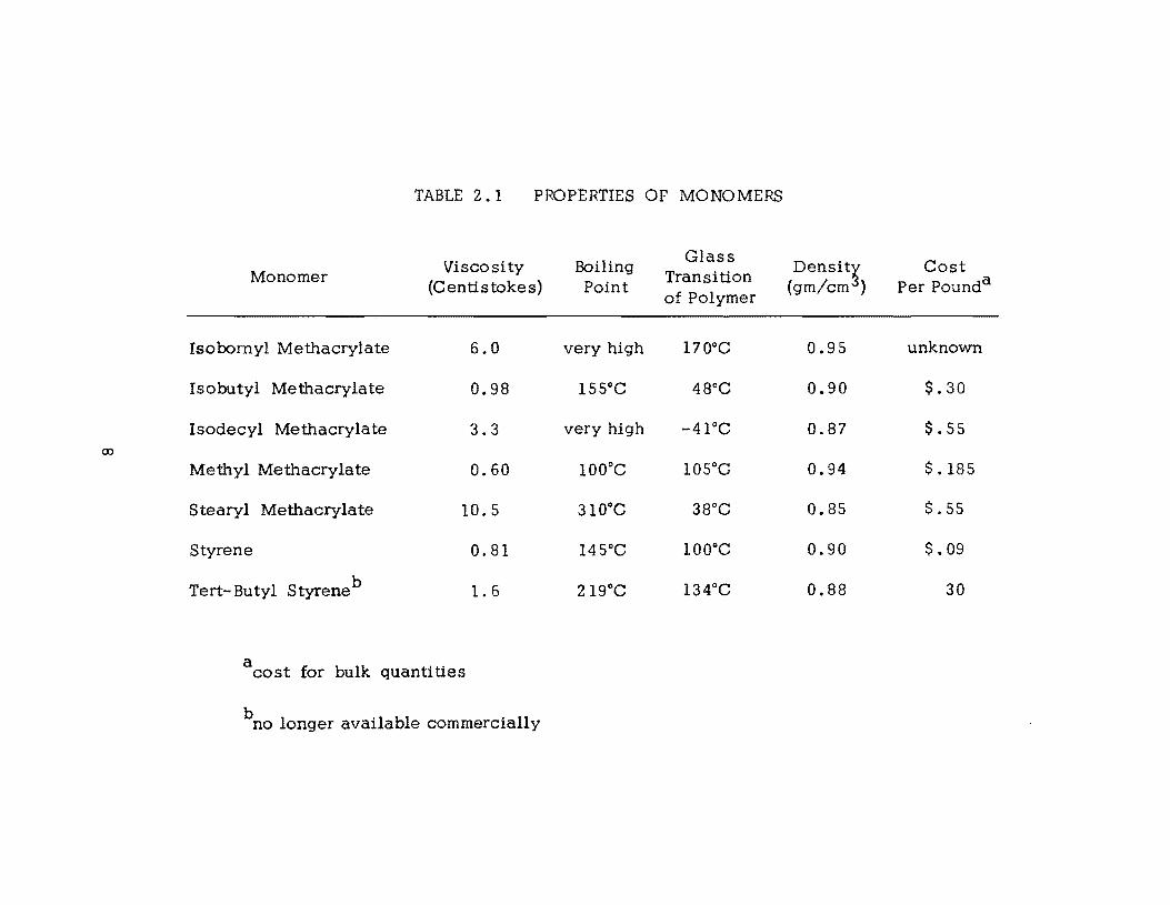
TABLE 2.1 PROPERTIES OF MONOMERS
Viscosity Boiling Glass
Densit~ Cost Monomer Transition
(Centistokes) Point of Polymer
(gm/cm ) Per Pounda
Isobornyl Methacrylate 6.0 very high 170°C 0.95 unknown
Isobutyl Methacrylate 0.98 155°C 48°C 0.90 $.30
Isodecyl Methacrylate 3.3 very high -41°C 0.87 $.55
Methyl Methacrylate 0.60 100°C 105°C 0.94 $.185
Stearyl Methacrylate 10.5 310°C 38°C 0.85 $.55
Styrene 0.81 145°C 100°C 0.90 $.09
Tert-Butyl Styreneb 1.6 219°C 134°C 0.88 30
acost for bulk quantities
bno longer available commercially
culminated in Table 2. I, is by no means exhaustive I and it is possible that
for some uses more nearly optimum monomers are available. These systems
have been identified simultaneously with developing a process for surface
impregnation. Future monomer screening would be aided by the perfection of
this process, and other monomer choices may be possible with different
processes.
So far methyl methacrylate (MMA) is the monomer which has been
used most extensively in this work. The reasons for this are that: (1) it has
been the most widely used monomer in previous polymer-impregnated studies
and therefore considerable information is availablei (2) early attempts at
surface treatment were most successful with this monomer compared to other
monomerSi and (3) it was convenient to gain experience with a single mono
mer while the application development was underway. Methyl methacrylate
is a very good monomer for surface treatmentsi however I its use here does
not imply that some other monomer would not be more optimum.
Polymerization of double-bonded monomers requires a source of free
radicals to initiate the reaction. Early work in polymer-impregnated concrete
used y rays from Cobalt 60 as the means of generating these reactive radi
cals.(20) This was convenient because the monomer could be allowed to
penetrate the concrete first and then be exposed to y rays only after this was
complete. In addition, the polymerization initiated by y rays can be carried
out at ambient temperatures. However I the use of radiation in highway sur-
face treatments is not practical so some other approach had to be pursued.
9
Polymerization of monomers on a commercial scale such as in plastics manu
facturing is frequ~ntly initiated by free radicals generated by the decomposi
tion of peroxides or other initiators. Polymerization is usually carried out at
elevated temperatures since this speeds up the reactions to an acceptable
level. A similar approach has been developed in this study for surface treat
ments which consists essentially of the following procedure. A peroxide
initiator is dissolved into the monomer and by necessity this must precede
penetration of the monomer into the concrete. A properly chosen sy stem will
not react at any noticeable rate at ambient temperature and so penetration
is possible. Once the monomer-initiator mixture has penetrated the concrete,
polymerization can be made to proceed at an acceptable rate by raising the
temperature of the concrete. The details of implementing this approach are
described in subsequent sections.
The heating required in this approach is a distinct disadvantage; how
ever, it appears to be a necessary part of a system that does not employ
radiation. A considerable effort was expended in trying to eliminate the need
for this step by using accelerators to catalyze the peroxide decomposition
as in the practice of many polymer casting operations where heat is not
applied. However, adequate penetration was never attained because polym
erization was occurring during the time the monomer was flowing into the
pores. Subsequent efforts were directed at selecting systems which would
minimize both the temperature and time required during the heating cycle.
Polymerization rate characteristics are one of the major factors to be
10
regulated in this process. For a given monomer, there are a number of
factors that can be used to adjust this rate. Those which have been em-
ployed are:
1. type and amount of peroxide (catalyst)
2. temperature
3. addition of a cross-linking agent (type and amount)
4. addition of an accelerator (type and amount)
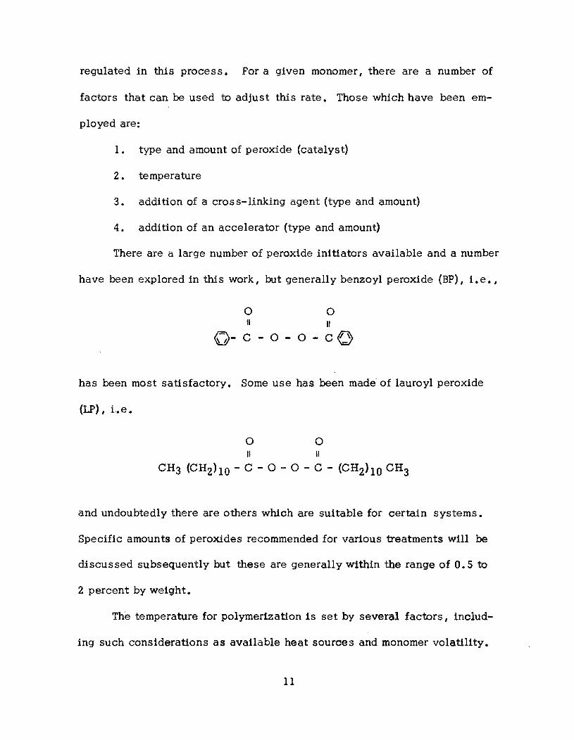
There are a large number of peroxide initiators available and a number
have been explored in thi s work, but generally benzoyl peroxide (BP), 1. e. ,
o o II "
(j-C-O-O-cO
has been most satisfactory. Some use has been made of lauroyl peroxide
(LF), i.e.
o o
" " CH3 (CH2)lO - C - 0 - 0 - C - (CH2)lO CH3
and undoubtedly there are others which are suitable for certain systems.
Specific amounts of peroxides recommended for various treatments will be
discussed subsequently but these are generally within the range of 0.5 to
2 percent by weight.
The temperature for polymerization is set by several factors, includ-
ing such considerations as available heat sources and monomer volatility.
11
During the early stages of process development it was realized that
the polymerization rate of methyl methacrylate was not as high as desired
and so the use of an additional monomer which is multi-functional was
adopted since its use had been shown to increase the polymerization rate
by Brookhaven workers .(20) Such agents also produce cross-linking in
the polymer and are I therefore I often referred to as cross-linking agents
although their principal reason for being used here is for the increase in
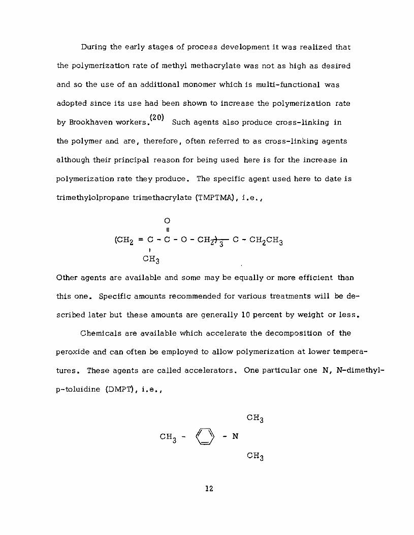
polymerization rate they produce. The specific agent used here to date is
trimethylolpropane trimethacrylate (TMPTMA) Ii. e. I
o II
(CH2 = C - C - 0 - CHzt"r- C - CH2CH3 I
CH3
Other agents are available and some may be equally or more efficient than
this one. Specific amounts recommended for various treatments will be de-
scribed later but these amounts are generally 10 percent by weight or less.
Chemicals are available which accelerate the decomposition of the
peroxide and can often be employed to allow polymerization at lower tempera-
tures. These agents are called accelerators. One particular one N I N-dimethyl-
p-toluidine (DMPT) I Le. I
CH3 - 0 - N
12
has been found particularly successful for the MMA-BP system. However I
research to date has been unsuccessful at using accelerators to reduce or
eliminate the need for heating in surface treatments. However I accelera
tors have been useful in other ways I such as to provide an overlay treatment
to heat up the concrete and in preparing monomer mixes for crack repair.
Laboratory test tube studies of polymerization rates have been found
useful but the results do not translate directly to polymerization inside the
concrete. A major reason for this is that polymerization is a highly exo
thermic reaction and so in bulk experiments the reaction mass heats up unless
the heat can be removed. In the concrete the large mass and the small size
of the pores insure that the monomer does not heat up. However I in the
laboratory it is almost impossible to avoid this temperature build-up. This
temperature rise then causes the rate of polymerization to increase. Thus
in general it is easier and requires less time to achieve polymerization in the
laboratory than in concrete. For this reason exact times for curing must be
worked out by actual studies with concrete rather than in test tubes.
Some laboratory experiments I however I do serve to illustrate some of
the important aspects of the current system and will be presented here. The
exotherm was followed as a key to the polymerization rate. In such cases
the sample size and thermal environment are very important factors which
must be carefully controlled and designed if the results are to be reproduc
ible. The system adopted is shown schematically in Fig. 2.1. It consi sts
of an aluminum plate resting on a bed of sand. A disposable aluminum pan
13
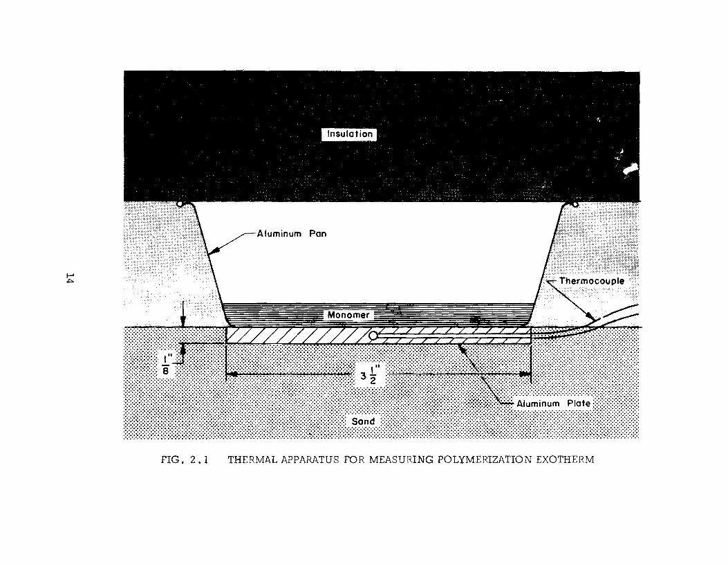
Aluminum Pon
FIG. 2.1 THERMAL APPARATUS FOR MEASURING POLYMERIZATION EXOTHERM
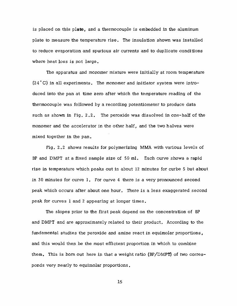
is placed on this plate, and a thermocouple is embedded in the aluminum
plate to measure the temperature rise. The insulation shown was installed
to reduce evaporation and spurious air currents and to duplicate conditions
where heat loss is not large.
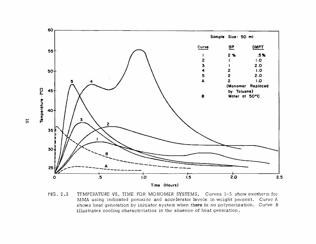
The apparatus and monomer mixture were initially at room temperature
(24 C C) in all experiments. The monomer and initiator system were intro
duced into the pan at time zero after which the temperature reading of the
thermocouple was followed by a recording potentiometer to produce data
such as shown in Fig. 2.2. The peroxide was dissolved in one-half of the
monomer and the accelerator in the other half, and the two halves were
mixed together in the pan.
Fig. 2.2 shows results for polymerizing MMA with various levels of
BP and DMPT at a fixed sample size of 50 ml. Each curve shows a rapid
rise in temperature which peaks out in about 12 minutes for cur be 5 but about
in 30 minutes for curve 1. For curve 4 there is a very pronounced second
peak which occurs after about one hour. There is a less exaggerated second
peak for curves I and 2 appearing at longer times.
The slopes prior to the first peak depend on the concentration of BP
and DMPT and are approximately related to their product. According to the
fundamental studies the peroxide and amine react in equimolar proportions,
and this would then be the most efficient proportion in which to combine
them. This is born out here in that a weight ratio (BP!DMPT) of two corres
ponds very nearly to equimolar proportions.
15
60
55
50
-0 45 t..
• ... :J -0 ... 40 • Go e
I-' (!! 0"1
30
25
o
FIG. 2.2
" '..... B ........
Sample
Curve
I 2 3 4 5 A
B
Size: 50 ml
BP DMPT
2% .5% I 1.0 I 2.0 2 1.0 2 2.0 2 1.0
(Monomer Replaced by Toluene) Water at 50·C
... ---- =:~::::::::::::::::::=========--=== --- ..... -... ~
A ----.------- ..... -------- ~-------------------.5 1.0 1.5 2.0
Time (Hours)
2.5
TEMPERATURE VS. TIME FOR MONOMER SYSTEMS. Curves 1-5 show exotherm for MMA using indicated peroxide and accelerator levels in weight percent. Curve A shows heat generation by initiator system when there 1s no polymerization. Curve B illustrates cooling characteristics in the absence of heat generation.
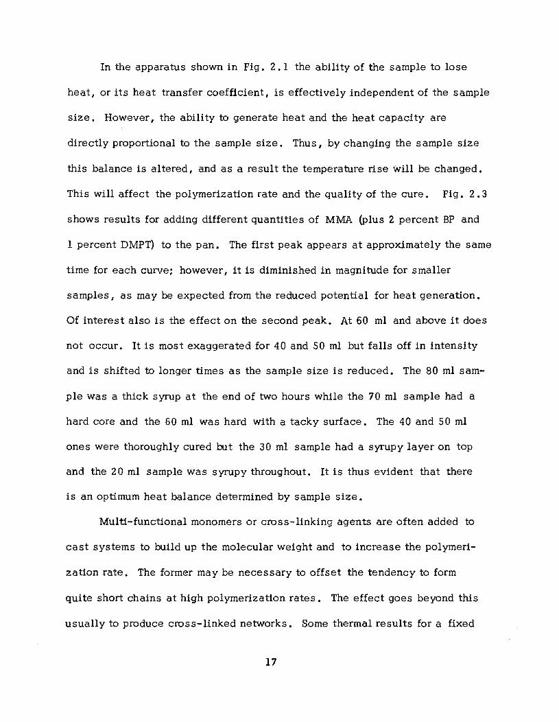
In the apparatus shown in Fig. 2.1 the ability of the sample to lose
heat, or its heat transfer coefficient, is effectively independent of the sample
size. However I the ability to generate heat and the heat capacity are
directly proportional to the sample size. Thus I by changing the sample size
this balance is altered, and as a result the temperature rise will be changed.
This will affect the polymerization rate and the quality of the cure. Fig. 2.3
shows results for adding different quantities of MMA (plus 2 percent BP and
1 percent DMPT) to the pan. The first peak appears at approximately the same
time for each curve: however, it is diminished in magnitude for smaller
samples I as may be expected from the reduced potential for heat generation.
Of interest also is the effect on the second peak. At 60 ml and above it does
not occur. It Is most exaggerated for 40 and 50 ml but falls off in intensity
and is shifted to longer times as the sample size is reduced. The 80 ml sam
ple was a thick syrup at the end of two hours while the 70 ml sample had a
hard core and the 60 ml was hard with a tacky surface. The 40 and 50 ml
ones were thoroughly cured rut the 30 ml sample had a syrupy layer on top
and the 20 ml sample was syrupy throughout. It is thus evident that there
is an optimum heat balance determined by sample size.
Multi-functional monomers or cross-linking agents are often added to
cast systems to build up the molecular weight and to increase the polymeri
zation rate. The former may be necessary to offset the tendency to form
quite short chains at high polymerization rates. The effect goes beyond this
usually to produce cross-linked networks. Some thermal results for a fixed
17
..... u !..
• '-:J -0 '-GI a.
I-' e
ex> ~
60r-------------------------------------------------------------------------~
55
50
45
40
35
30
25
o
80 ml = Sample Size
20
.5 1.0
Time (Hours)
1.5
Methyl Methacrylate Peroxide: 2% Benzoyl Accelerator: 1% DMPT
2.0
FIG. 2.3 EFFECT OF SAMPLE SIZE ON THE NATURE OF THE EXOTHERM
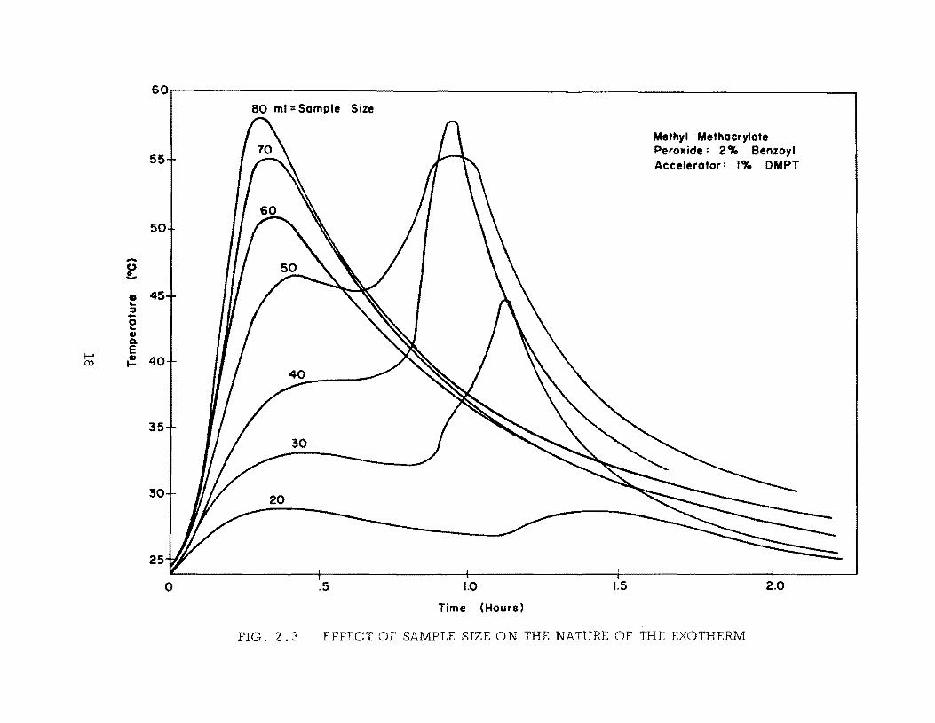
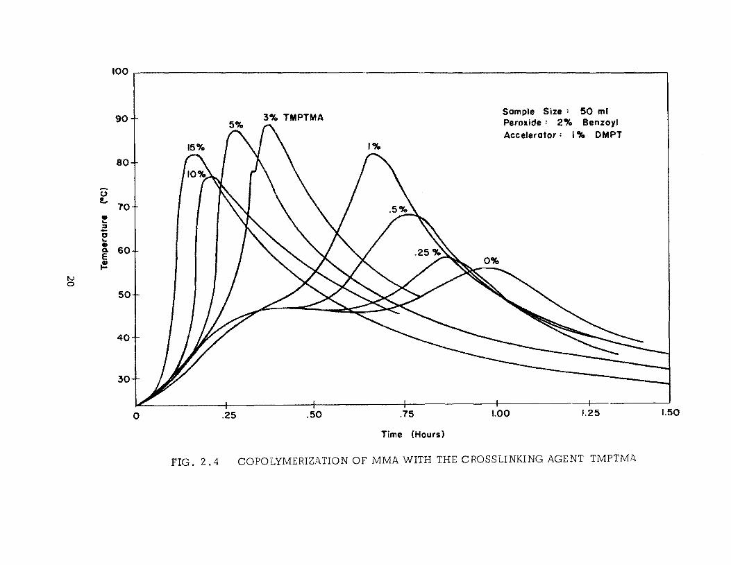
sample size and initiator system but varyling levels of TMPTMA are shown
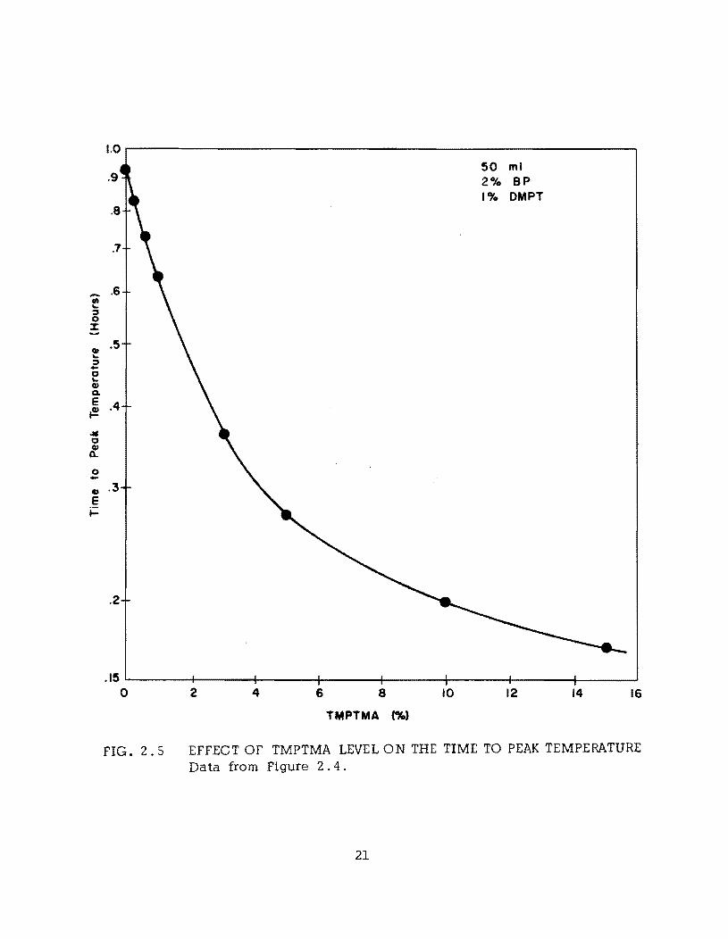
in Fig. 2.4. As the proportion of this agent is increased, the second peak
is increased in magnitude and shifted to shorter times to the point where it
merges with or surpasses the first peak. Fig. 2.5 illustrates the uniform
shift of this peak. TMPTMA has a very profound effect on the polymeriza
tion rate.
All of the products were very hard with no tacky surfaces. However I
another effect is produced in the product by the cross-linking that occurs,
viz I brittleness. The samples with the highest contents of TMPTMA were
so brittle that they were cracked from thermal stresses. This problem
diminished as the TMPTMA content was decreased.
2.2 Preliminary Monomer Penetration Studies
In the preliminary phase of the investigation, qualitative studies were
made to determine the effect of several variables on monomer penetration
into concrete. The variables were viscosity, temperature, soak time, surface
preparation, and hydrostatic pressure. The tests were performed on 6 x 10 x
10-in. concrete slabs. Monomer was ponded in 4-in.-diameter steel rings
bonded to the surface with silicone adhesive. Two rings were used per slab.
Plastic film was placed over the rings to prevent evaporation during the soak
ing period. At the end of the soaking period, excess monomer was poured
off, the rings were removed, and the specimen was immediately broken across
both wetted areas. Initially, dye was used in the monomer to determine pene
tration depth, but this was discontinued when it was found that the dye filtered
19
.... (.) t..
• ... ;:, -g ... • 0. E ~
tv 0
100r-------------------------------------------------------------------~
90
80
70
60
50
40
30
o .25
FIG. 2.4
3% TMPTMA
.50 .75
Time (Hours)
Sample Size: 50 ml Peroxide: 2% Benzoyl Accelerator: 1% DMPT
1.00 1.25
COPOLYMERIZATION OF MMA WITH THE CROSSLINKING AGENT TMPTMA
1.50
-III ~
~ 0 %
at ~
~ -0 ~
at 0. E {!
"" 0
t. 0 -at E t=
1.0 r----------------------------.
.9
.7
.6
.5
.4
.3
.2
50 ml 20/. BP 1% DMPT
.15 1-----I------I,.-----+----+---t----I------4--~ o 2 4 6 8 10 12 14 16
TMPTMA (%)
FIG. 2.5 EFFECT OF TMPTMA LEVEL ON THE TIME TO PEAK TEMPERATURE Data from Figure 2.4.
21
out near the slab surface. Thereafter I the depth of penetration was marked
on the broken sur.·ace.
Only MMA alone and a solution of MMA and a low molecular weight
acrylic copolymer {Rohm and Haas 6906-XP} were used in this preliminary
investigation. The copolymer was used to reduce the vapor pressure since
it was assumed early in the investigation that evaporation would be one
of the most seriour problems to be overcome in developing surface treat
ments. No attempt was made in these preliminary tests to polymerize the
monomer.
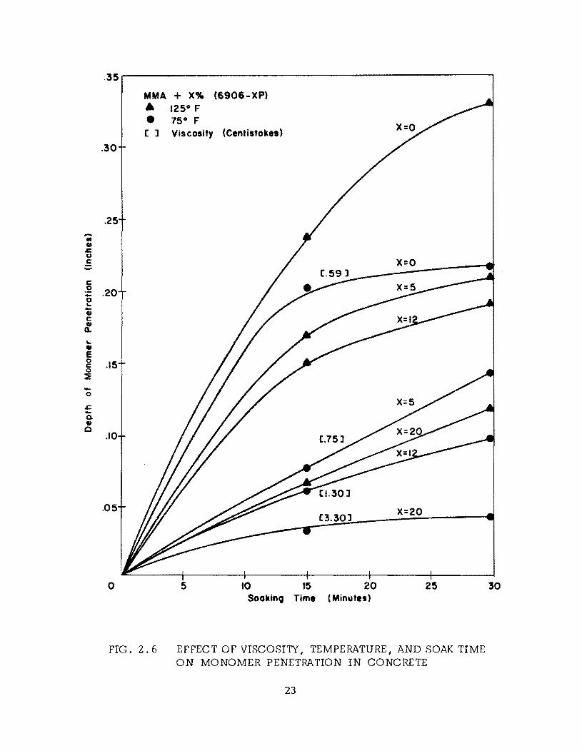
The effects of viscosity I temperature and soak time on monomer pene
tration into the concrete are shown in Fig. 2.6. Viscosities are shown
only for the monomer applied to concrete at room temperature. The vis
cosity was varied by addition of the copolymer. The penetration was
significantly affected by viscosity and by slab temperature. It was later
found that the soak time should be longer than those shown in Fig. 2.6 I
but the qualitative results were useful in determining relative importance
of the variables.
The condition of the surface was found to affect penetration. Tex
tured surfaces were found to be more easily penetrated by the monomer than
smooth troweled ones. Wire brushing parallel to the screeding lines on
the surface also aided penetration; this seems to be the result of breaking
the concrete surface film formed during the hydration of the concrete.
22
.... .-., .c u c: ..... c: .2 -0
'" -., c: :. '" • e 0 c 0 ~ -0
s::. -Q, ., 0
.35
MMA + X% (6906-XP)
• 1250 F
• 75 0 F [ ] Viscosity (Centiltoke. )
.30
.25
X=O
.20
.15
.10
.05 [3.30] X=20
o 5 10 15 20 25 Soakin9 Time (Minutes)
FIG. 2.6 EFFECT OF VISCOSI1Y I TEMPERATURE I AND SOAK TIME ON MONOMER PENETRATION IN CONCRETE
23
30

Increasing the depth of monomer from 1/8 in. to 1/4 in. had no
perceptible effect on monomer penetration. As noted in section 2.1 1
capillary forces seem to predominate. Later tests verified that no pond
ing was necessary to achieve satisfactory penetration.
24
CHAPTER 3.
Surlace Treatments
3. 1 Statement of Problem
The studies reported in chapter 2 permitted a better understanding of
the problems associated with obtaining surlace treatments in concrete.
However, these studies yielded primarily qualitative information, and these
results could not be used to directly predict performance of surface treat
ments. It became obvious that the pasic investigations of monomer sys
tems and penetration would have to be supplemented by actual tests on
concrete using realistic conditions.
In the early phases of the investigation, three major problems in
obtaining satisfactory surlace treatments were identified. They were:
3.1.1 Development of Monomer Systems--As discussed in section
2.1, monomer systems that could successfully be polymerized at room
temperature in test tubes were not found to polymerize in the concrete at
room temperatures. It became obvious that the addition of either cross
linking agents, accelerators, heat, or some combination of these, to the
monomer and catalyst would be necessary to obtain polymerization in con
crete. The search for suitable monomer systems became essentially a
25
trial and error solution, using concrete slabs and the trial monomer
system.
3.1.2 Application Technigues--From the beginning of the studies
it was known that evaporation posed a potential problem since most low
viscosity monomers suitable for surface treatment have low vapor pres-
sures. For surface treatments the problem was more pronounced because
of the large surface-to-volume ratio and the time required for penetration.
The use of evacuation (application of a vacuum) and overpressure to
accelerate the saturation of the concrete was not considered to be feas-
ible, even though some investigators have used them for small laboratory
. (25) speCImens.
3.1.3 Curing Methods--After little success was achieved using
room temperature polymerization, it became necessary to investigate
methods of supplying external energy to assist polymerization. Use of
nuclear irradiation, extensively used for laboratory specimens ,(20) was
not deemed feasible because of both the weight of the portable field
apparatus required and the safety hazards involved. To be successful the
curing method had to be economical, available outside urban areas, safe,
and suitable for treating large areas of concrete.
3.2 Development of Monomer Systems
3.2.1 Procedures--The general procedure for investigating surface
treatments was to dry the slabs, mix the monomer solution, soak the solu-
tion into the slab I cure the concrete, break the slabs, and record the
results. 26
All of the laboratory tests were performed on 2 x 10 x 10-in. or 6 x 10
x 10-in. slabs to which 1 x 9-1/2 x 9-1/2 in. metal frames (Fig. 3.1) or
4-in.-diameter metal rings were attached. The rings were used initially be
cause two could be used on each slab. However I the edge effects were
large as evidenced by the presence of only a small amount of polymer in the
center of the rings. For that reason the larger square frames have been used
in nearly all of the later studies. Six-in.-thick slabs were used initially
and are still used for slabs which are evaluated for durability. Two-inch
s 1 a bs, which are more ea s11 y handled and require Ie s s concre te I are u sed in
the qualitative tests to determine the results of a treatment.
3.2.2 Monomer System Investigated--Approximately 20 or 25 mono
mers I or combinations of monomers I have been investigated for feasibility.
Most of these have been methacrylates. Several of these have produced
satisfactory surface treatments of 1/2-in. depths or more. Combinations of
styrene and polyester were used. However I because of the high viscosity
of the polyester I adequate penetration could not be achieved even with a
solution containing 90 percent styrene by volume.
The monomers selected for further study were:
1. methyl methacrylate (MMA)
2. isobutyl methacrylate (IBMA)
3. isodecyl methacrylate (IDMA)
4. butyl acrylate (SA)
5. isobutyl acrylate (IBA)
6. butyl methacrylate (BMA)
27
The last three have only recently been identified as being successful for
surface treatmentj, and evaluation tests have just begun. In addition, tert
butyl styrene indicated considerable potential, but it has been discontinued
by the manufacturer. All of the monomer systems utilize 1 percent (wt)
benzoyl peroxide (BP) as the catalyst and 10 percent (wt) cross-linking
agent, trimethylolpropane trimethacrylate (TMPTMA). All of these systems
have been shown to polymerize in concrete at a temperature of 1251:'.
Several methods of combining the catalyst and monomer were attempted.
The most common method reported by others (2 0) and the most successful
method in this project was to mix the catalyst in the monomer before applica
tion to the concrete. However, potential safety hazards would be involved
if large quantities of monomer solution were mixed before application to the
concrete.
Another method investigated was to deposit the catalyst, using 2 to
5 percent of the estimated polymer weight in the concrete, in the saturated
pores in the cured concrete with acetone. The theory was that the acetone
would evaporate, leaving the BP in the pores of the concrete to later react
with the monomer solution. A solution of MMA and cross-linking agent
was soaked into the concrete and after soaking, heat was applied to polym-
erize the monomer. However I only one specimen out of five showed any
polymer I and it was shallow and faint.
Another means of introducing BP into the concrete was to mix it in
the fresh concrete. This was attempted using BP paste instead of dry
28
powder. Sufficient BP (0.22 lbs./cu.ft. of concrete) was added to provide
2.5 percent of BP for a 6 percent (wt) monomer loading. However, an ad-
verse reaction took place in the concrete mix with the BP present. The
compressive strength (2420 psi) was approximately one-half of the values
found for similar mixes without BP present. Surface treatments were
attempted using MMA and TMPTMA soaked into the concrete, but only
slight traces of polymer were obtained.
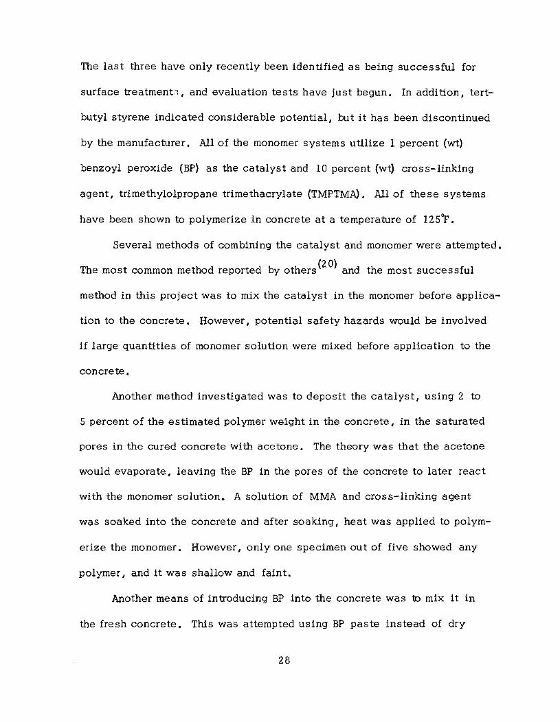
3.3 Application Techniques
Application techniques were developed using 2 x 10 x 10-in. and
6 x 10 x 10-in. concrete slabs in the laboratory and 5-1/2 x 40 x 43-in.
slabs in the field. Application consisted of drying the slabs, soaking
the slabs with monomer solution (Pig. 3.1), preventing evaporation, and
curing.
3.3. 1 Drying-- Drying of the concrete to remove free water has
been found to be important. (20) The effect on surface treatments was
evaluated qualitatively by treating air dried and oven dried (17S0
P) 2-in.
and 6-in. slabs with a monomer system using MMA. After curing, the
oven-dried slabs had approximately three times greater polymer depth, and,
in addition, the polymer was darker, indicating a higher polymer loading.
Slabs used for qualitative surface treatment were dried at 12 SOp or
17So p for a minimum of three days. Treated slabs used for evaluation pur-
poses were dried for a minimum of seven days. Pield treated slabs were
left exposed to the air for a minimum of two months before being covered
29

with polyethylene film to prevent saturation with rain. Heating blankets
were then applied ;;lnd left in place a minimum of three days.
While heating blankets may not be feasible for large- scale treat
ments, the use of plastic covers to keep the surface dry and to absorb
solar heat to assist the drying process does seem practical. For acceler
ated drying, heaters placed under a plastic sheet enclosure or a warm
forced-air system could be used.
3.3.2 Evaporation Barriers-- Ini tiall y monomer was ponded to a
depth of 1/8 to 1/4 in. on level 10 x la-in. slab specimens to provide
a surplus of monomer to compensate for evaporation loss. Plastic-wrapped
plywood was placed over the metal frames to minimize evaporation. The
slabs were then placed in an oven at 125°F to polymerize the monomer.
However, only a shallow depth (= 1/8 to 1/4 in.) of polymer was obtained,
and there was usually a thin (= 0.05 in.) zone of unpolymerized concrete
at the surface caused by evaporation.
It was found that a thin (= 1/4 in.) layer of fine aggregate placed on
the top of the slab served as an evaporation barrier. The monomer could be
applied in sufficient quantities to wet the sand, and the sand served as a
wick for the slab. This permitted a much longer soak time without the
monomer evaporating completely off the surface. Initially lightweight aggre
gate fines were used since, because of their skid resistant characteristics,
it was theorized that if the aggregates were bonded to the surface during
polymerization, a skid resistant surface would result. The sieve analysis
30
for all of the lightweight aggregate used in the tests reported is given in
Table A. 3 in the appendix.
More recently it has been found that the use of regular fine aggregate
seems to yield deeper surface treatments. This can probably be explained
by the fact that the more porous lightweight aggregate is a better insulator
and prevents the concrete from reaching as high a temperature as when
normal aggregate is used during the curing process.
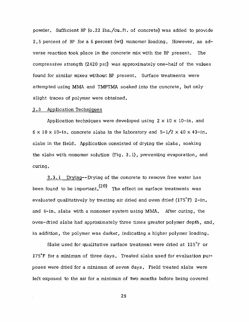
Since actual bridge decks are sloped to permit drainage of water I
tests were performed on sloped slabs to determine if adequate penetration
of the monomer could be achieved. Small laboratory slabs and the larger
field treated slabs were sloped 1/4 in. 1ft. The field treated slabs were
covered with l/4-in. oven-dried lightweight aggregate fines (Fig. 3.2).
Current tests are underway on slabs covered with natural sand.
3.3.3 Monomer Application--In the laboratory I the monomer solu
tion was mixed in beakers and poured onto the slabs with the metal frames
and, in later treatments, sand cover. The initial volume of monomer
usually varied between 250 ml and 400 ml. The specimens were covered
with the plastic wrapped plywood to help prevent evaporation. If during
the soaking period, the sand became dry, additional monomer (100 ml) was
added.
For the larger field-treated slabs, the monomer was mixed in and
applied with galvanized water sprinkler cans (Fig. 3.2). The slabs were
immediately covered with polyethylene film to minimize evaporation losses.
31
FIG. 3.1 APPLICATION OF MONOMER TO 2 IN. SLAB COVERED WITH FINE AGGREGATE
FIG. 3.2 APPLICATION OF MONOMER DURING FIELD TREATMENT OF SLOPED SLABS WITH FINE AGGREGATE COVER
32
On warm, sunny days when the exposed slab temperature would exceed 1000 F,
the slabs were shaded to prevent premature polymerization before adequate
penetration had been achieved. Additional monomer solution was added if
the lightweight fines became dry. It was usually observed that lBMA had
less tendency to dry out on the surface than did MMA.
It should be emphasized that most treatments to date have had the pri
mary purpose of either determining the feasibility of monomer systems or
treating slabs to be evaluated for durability. In most cases, the monomer
was applied rather liberally to insure a good treatment. However, this in
vestigation is also concerned with optimizing the procedures to obtain the
most economical treatments possible. Current studies are underway to de
termine the minimum amount of monomer solution consistent with acceptable
treatments.
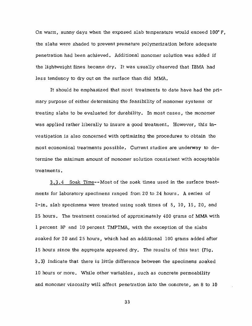
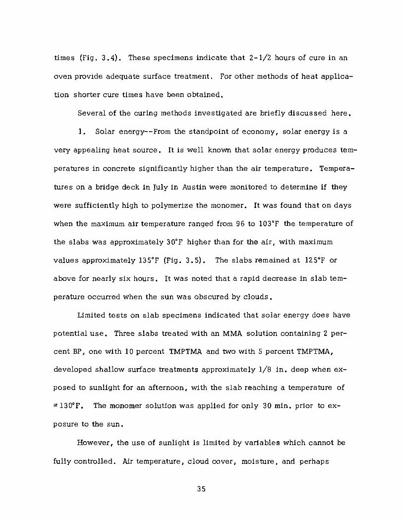
3.3.4 Soak Time-- Most of the soak times used in the surface treat
ments for laboratory specimens ranged from 2 a to 24 hours. A series of
2-in. slab specimens were treated using soak times of 5, 10, IS, 20, and
25 hours. The treatment consisted of approximately 400 grams of MMA with
1 percent BP and 10 percent TMPTMA, with the exception of the slabs
soaked for 20 and 25 hours, which had an additional 100 grams added after
15 hours since the aggregate appeared dry. The results of this test (Pig.
3.3) indicate that there is little difference between the specimens soaked
10 hours or more. While other variables, such as concrete permeability
and monomer viscosity will affect penetration into the concrete, an 8 to 10
33
hour minimum soak time seems adequate for MMA in most cases.
These results may not seem consistent with the data presented in
chapter 2 from the penetration tes ts, which indicate monomer penetration
of greater than 1/4 in. after 30 minutes of soak time. However, when a
slab is placed in the oven to cure after a 30 minute soak time, the result
ing depth of polymer impregnation is approximately liS in. This seems
to indicate that for short soak times the concrete pore walls are visibly
wetted but the pores are not filled. The longer soak times are necessary
to fill the pores. It should be emphasized that in order for the longer
soak times to be effective, it is necessary to keep the sand moist.
3.3. S Methods of Curing--Considerable effort has been expended
on developing simple, practical methods for polymerizing the monomer sys
tem in slab surfaces. Initially in the investigation, specimens were placed
in a l2SoP oven for curing while more practical methods for curing large
areas of bridge decks in the field were investigated. The value of 12 sop
was selected since it represented the lowest nominal temperature at which
polymerization would occur in a reasonable time period. Unless a heat
generating system could produce slab surface temperatures of at least l2So p I
it was not considered a potential solution.
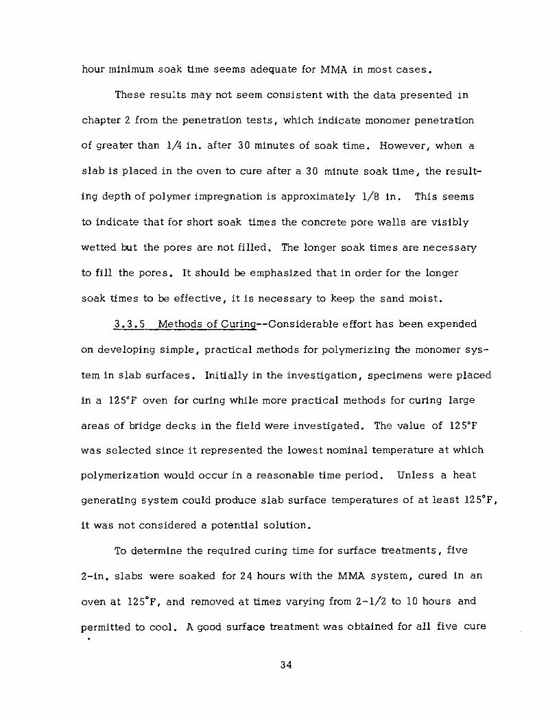
To determine the required curing time for surface treatments, five
2-in. slabs were soaked for 24 hours with the MMA system, cured in an
oven at l2Sop, and removed at times varying from 2-1/2 to 10 hours and
permitted to cool. A good surface treatment was obtained for all five cure
34
times (Pig. 3.4). These specimens indicate that 2-1/2 hours of cure in an
oven provide adequate surface treatment. Por other methods of heat applica
tion shorter cure times have been obtained.
Several of the curing methods investigated are briefly discussed here.
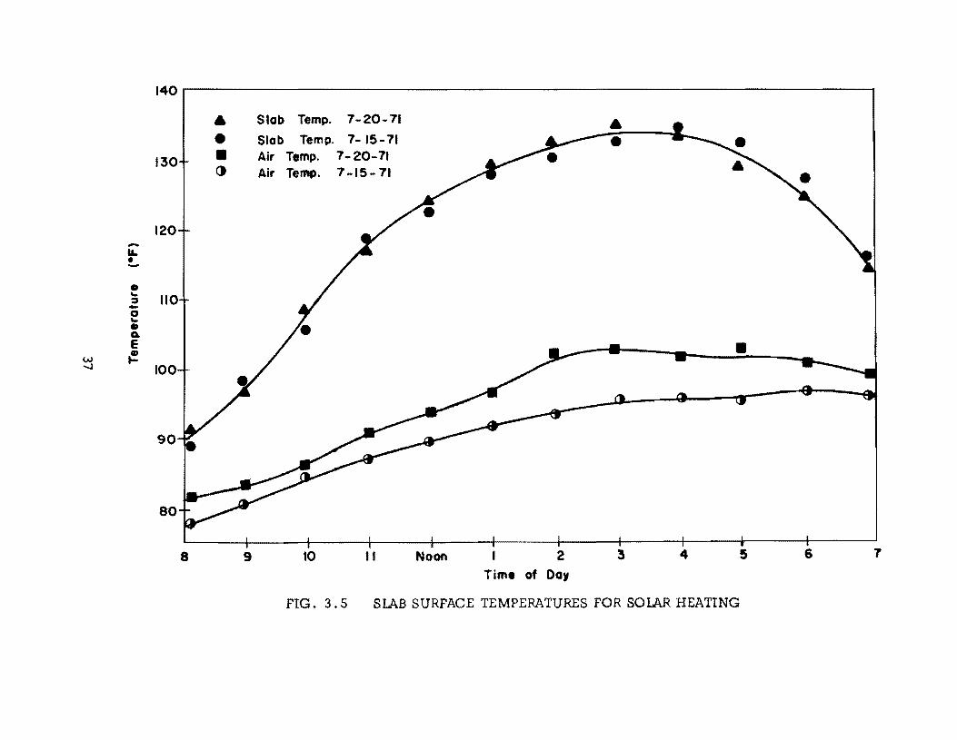
1. Solar energy--Prom the standpoint of economy I solar energy is a
very appealing heat source. It is well known that solar energy produces tem
peratures in concrete significantly higher than the air temperature. Tempera
tures on a bridge deck in July in Austin were monitored to determine if they
were suffiCiently high to polymerize the monomer. It was found that on days
when the maximum air temperature ranged from 96 to 103°P the temperature of
the slabs was approximately 300 P higher than for the air, with maximum
values approximately 135°P (Pig. 3.5). The slabs remained at 12 Sop or
above for nearly six hours. It was noted that a rapid decrease in slab tem
perature occurred when the sun was obscured by clouds.
Limited tests on slab specimens indicated that solar energy does have
potential use. Three slabs treated with an MMA solution containing 2 per
cent BP ,one with 10 percent TMPTMA and two with 5 percent TMPTMA,
developed shallow surface treatments approximately 1/8 in. deep when ex
posed to sunlight for an afternoon, with the slab reaching a temperature of
:::: 130o P. The monomer solution was applied for only 30 min. prior to ex
posure to the sun.
However, the use of sunlight is limited by variables which cannot be
fully controlled. Air temperature I cloud cover I moisture, and perhaps
35
FIG. 3.3 EFFECT OF SOAK TIME ON PO LYMER DEPTH (5 , 10, 15, 20, a nd 25 hrs -top to bottom)
FIG. 3 .4 EFFECT OF CURING TIME AT 1250 F (2~, 4, S~, 7, and 10 hrs--top to bottom)
-tL • -• ... :::t -0 ... • Q. e
w ~ --.l
140.------------------------------------------------------------------------,
130
120
110
100
90
80
8
A
• • ()
9
Slab Temp. 7-20-71
Slab Temp. 7- 15-71 Air Temp. 7 - 20-71 Air Temp. 7-15-71
10 II Noon 2 Time of Dar
•
•
3 4 5
FIG. 3.5 SlAB SURFACE TEMPERATURES FOR SOlAR HEATING
6 7
relative humidity affect slab temperatures. Treatments would have to be on
a day-to-day bas:s, which would make planning difficult. In many parts of
the U. S. sufficiemt temperatures for polymerization would occur in only a
few months each year. Also, surface evaporation would probably be more
difficult to control. For these reasons solar energy has not been considered
a prime method for polymerization.
2. Microwave heating--Some attempts were made to introduce heat
into the slabs by the use of microwaves. A microwave oven, commonly
used to heat pastries, was obtained to explore the potential of this tech
nique. The concrete slabs were treated with monomer in the standard
fashion. After the desired penetration was achieved, the excess monomer
was removed and the 2-in. concrete slab was broken into approximately
5 x 5-in. pieces. The specimens were broken because they were too large
to be accommodated by the oven. Each specimen was placed in the oven
and heated for various time intervals. Temperatures of the specimens were
taken upon removal from the oven. Fluctuation of these temperatures was
very great, presumably because of the variations in the mass of the concrete
placed in the oven. No quantitative studies were performed to verify this
assumption. No data are shown, since only very limited success with the
microwave oven resulted when twenty slabs were treated and cured. The
feasibility of using microwave heating for field conditions seems improbable
at this time.
3. Reactive Monomer System--The use of a second, more reactive
38
treatment that could be applied over the usual initial treatment was explored
with the goal of developing sufficient heat to cause polymerization. One
reactive monomer system that has shown some potential consisted of MMA,
4 percent lauroyl peroxide and 4 percent N, N-dimethyl-p-toluidine. This
solution, when ponded on the surface of specimens already saturated with
MMA, benzoyl peroxide and TMPTMA, achieved polymerization within two
hours. Typically the heat generated will polymerize the initial monomer
treatment to a depth of a quarter-inch or less, although in one specimen a
polymer depth of 3/4 in. was obtained. The sand cover serves an addi
tional purpose, providing a friction-resistant surface instead of the glossy
polymer coating that could develop on the slab. The second treatment
serves, initially, as an evaporation barrier and, after polymerization, as
a wearing surface, which may be more important than its heat-generating
capabilities. In most current investigations additional heat sources are
applied for curing even when the second treatment is used.
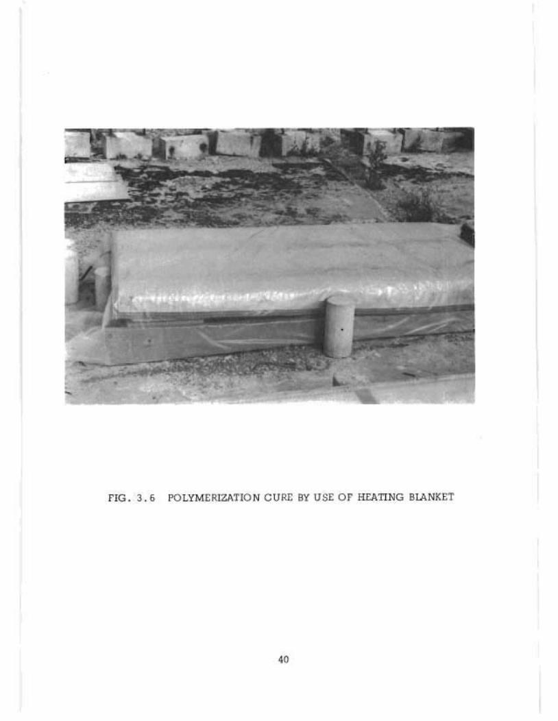
4. Heating Blankets--Heating blankets, which have long been used
in cold climates to cure concrete, were investigated for use. The blankets
are capable of developing relatively high concrete temperatures. Several
field-treated slab specimens used heating blankets with a capacity of 25
watts/sq. ft. as the energy source for polymerization (Pig. 3.6). The
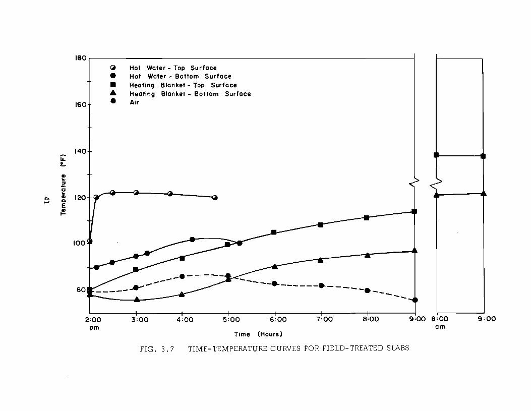
time-temperature relationship for a typical treatment is shown in Pig. 3.7.
Slab temperatures were measured with thermocouples mounted on the surface.
Top surface temperatures in the range of 1400 P or more were reached;
39
riG. 3.6 POLYMERIZATION CURE IN USE or HI:ATING BlANKET
..
--IL. !..
e ~
::J -C ~
~ .,
f-' a. E ~
180.-------------------------------------------------------------~
160
140
120
100
80
2:00
~ Hot Water - Top Surface • Hot Water - Bottom Surface
• • • Heating Blanket - Top Surface Heating Blanket - Bottom Surface Air
---3:00
.-----4:00
--5:00
......... -e.-__ ---e_--- ..... -~ ......... ---6:00 7:00 8:00 9:00 8:00
pm am Time (Hours)
FIG. 3.7 TIME-TEMPERATURE CURVES FOR FIELD-TREATED SLABS
9:00
however, these temperatures were reached very slowly, which required the
addition of considerable amounts of monomer to keep the fine aggregate
moist. Polymerization was achieved, and heating blankets represent one
method of heat generation.
S. Steam--Steam was used to cure several slab specimens. Mter
soaking overnight with the monomer system, the slab surfaces were sprayed
with steam. The three slabs shown in Fig. 3.8 were steam cured for 4, 8
and 11 minutes. The depth of polymer was approximately 3/4 in.; however,
the evaporation due to the high surface temperature was exces sive, ranging
from 1/8 to 3/16 in. A number of evaporation barriers, including sand,
wet burlap, sheet metal, and polyethylene, were tried with little success.
However, the use of a steam curtain, used for curing in concrete
products plants, is being investigated. An enclosure made of canvas or
plastic film is placed over the slab. Steam is supplied to the enclosed
space to heat up the slab. Since steam is not applied directly to the sur
face of the slab, the evaporation losses are reduced. Current tests indi
cate that the steam curtain method is capable of generating slab tempera
tures in excess of 200°F in a short period of time. While these high
temperatures are probably not desirable for bridge decks, they do indicate
the potential of this method. Using 2-in. slabs, polymer treatments have
reached a depth of 1-3/4 in. Further tests could indicate that this method
is the simplest and most economical.
42
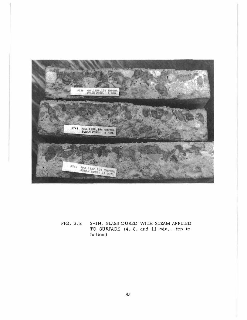
FIG. 3.8 2-IN. SLABS CURED WITH STEAM APPLIED TO SURFACE (4. 8. and 11 min. -- top to bottom)
43
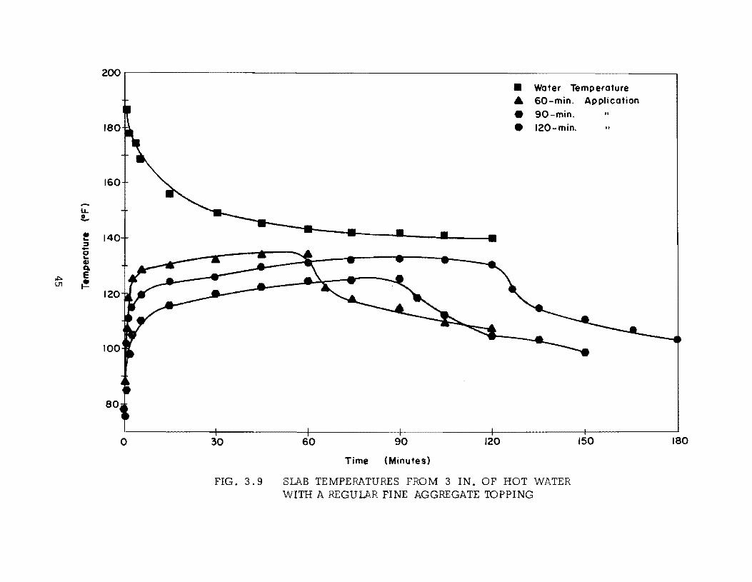
6. Hot Water--One very succes sful means of polymerization to date
has been the use of hot (=190"P) water. Mter the soak period, a poly
ethylene sheet is placed over the sand cover and turned up the side of a
frame around the edges to form a pond for the water. Hot water is ponded
to a depth of approximately 3-in. In the laboratory the temperature of
2 x lOx 1 O-in. slabs was monitored by a thermocouple mounted on the
slab surface beneath the regular fine aggregate for three different water
application times (Pig. 3. 9). The slabs were insulated around the edges
to minimize the heat flow. As the hot water was removed, the slab tem
perature dropped significantly after reaching a maximum of 125 to 135"P.
This compares to a maximum of about 120"F when lightweight aggregate
fines were used (Pig. 3.7).
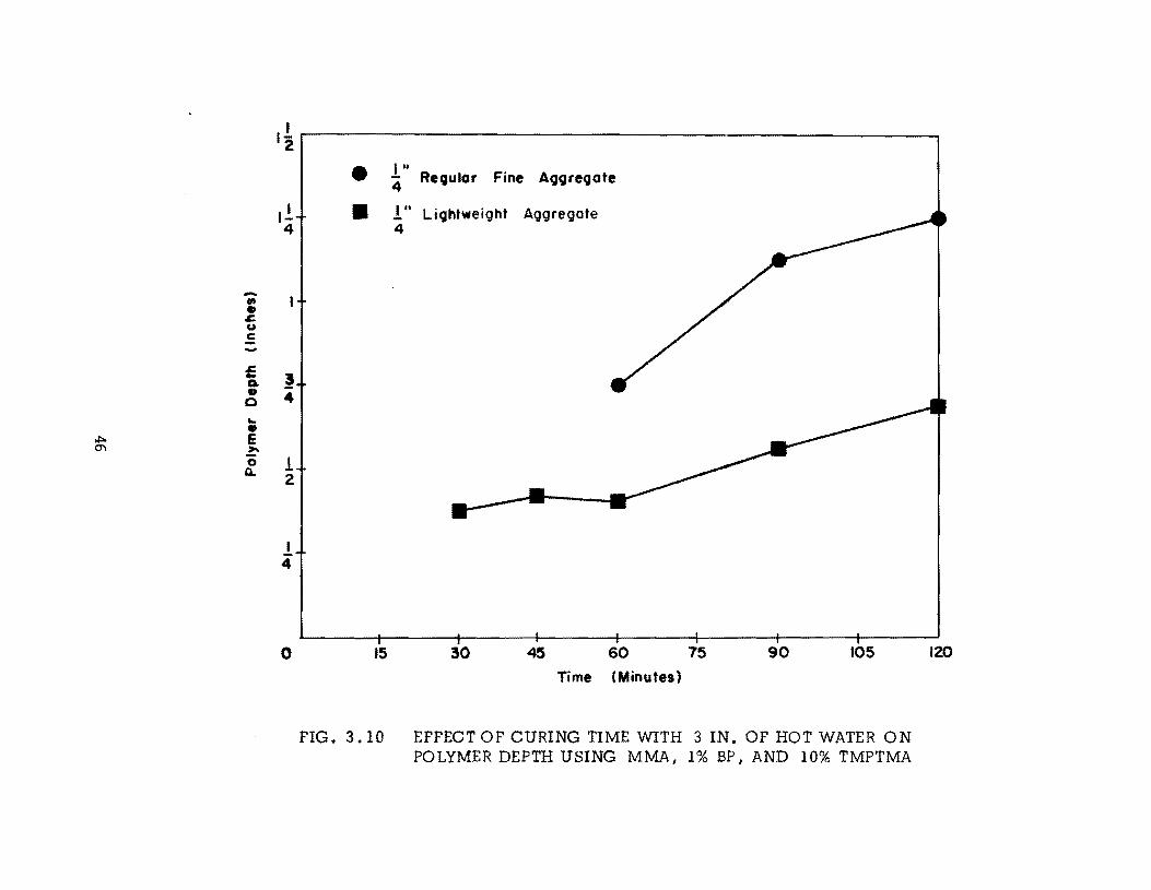
A comparison of the polymer depth versus hot water application time
for slabs covered with the two types of aggregate is shown in Pig. 3.10.
The insulating effect of the lightweight aggregate was found to be signifi
cant. The use of regular aggregate produces a 3/4-in. polymer depth in
one hour while lightweight aggregate requires two hours.
Pield treatments on larger slabs have yielded good temperatures even
in cold weather. In a recent treatment during a day on which the air tem
perature failed to reach the predicted high of 70"P, a scheduled treatment
was continued even though the air temperature reached only 50"P. Within
minutes of the hot water application, the slab temperature reached 138"P.
Regular fine aggregate was used in this treatment.
44
200
180
160
LL !...
! :J -a '-CI)
a. ~ e V1 ~
o 30
FIG. 3.9
• Water Temperature
• 60-min.
• 90-min.
• 120-min.
60 90 120
Time (Minutes)
SLAB TEMPERATURES FROM 3 IN. OF HOT WATER WITH A REGULAR FINE AGGREGATE 'IDPPING
Application ..
150 180
-., • .I:. Co)
C ..... -£ II. • 0 .. • ~ e
'" ,.. '0 a..
,! r---------------------------------------------------------~ 2
• 1 .. '4 Revular Fine AQQreQate
,! .! It LiQhtweight Aggregate 4 4
! 4
! 2
! 4
o 15 30 45 60 75 90 105
Time (Minutes)
FIG. 3.10 EFFECT OF CURING TIME WITH 3 IN. OF HOT WATER ON POLYMER DEPTH USING MMA, 1% BP I AND 10% TMPTMA
120
7. Warm Air--Warm air ovens have been extensively used to cure
the small slabs. Temperatures of l25°P have been adequate to produce good
surface treatments. The sand cover prevents evaporation from the slab sur
face. While ovens per se would not be feasible for curing bridge decks,
heaters placed in enclosures over the slab or forced-air heating systems with
ducts into an enclosure would accomplish the same purpose. A simple frame
one to two feet in height with a canvas or insulated panel covering would
provide the enclosure.
3.4 Summary of Treated Slabs
Several hundred slabs have been treated to qualitatively evaluate
monomer systems, application techniques, and curing methods. In addi
tion, three types of slabs have been treated for the purpose of performing
quantitative evaluation tests. * The treatments utilize the application and
curing techniques described in section 3.3. The monomer solution was
applied quite liberally to ensure an adequate treatment. The treatments
and resulting depth of polymer impregnation are summarized here.
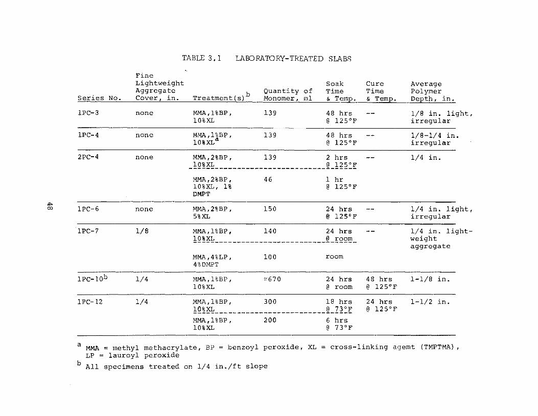
3.4.1 Laboratory-Treated Slabs--Seven series of five or more 5 x
10 x 10-in. slabs were treated with MMA monomer solutions. These
treatments are summarized in Table 3.1. All specimens soaked or cured
at 125° F were placed in an oven.
The first four series of slabs were treated before the advantages of
using fine aggregate evaporation barriers were known. In addition, these
*Mix designs are given in Table A.I in the appendix.
47
Series No.
IPC-3
IPC-4
2PC-4
IPC-6
IPC-7
IPC-IOb
IPC-12
TABLE 3.1 LABORA~RY-TREATED SLABS
Pine Soak Lightweight
Aggregate Cover, in. Treatment(s)b
Quantity Monomer,
of Time ml & Temp.
none MMA,l%BP, 139 48 hrs 10%XL @ 125°P
none MMA,l%BP, 10%XLa 139 48 hrs
@ 125°P
none MMA,2%BP, 139 2 hrs
none
1/8
1/4
1/4
_~Q!~ _________________________ ~_!~2~!
MMA,2%BP, 10%XL, 1% DMPT
MMA,2%BP, 5%XL
46
150 24 hrs @ 125°P
MMA,l%BP, 140 24 hrs !Q~~~ _________________________ ~_EQQ~_
MMA ,4%LP, 4%DMPT
MMA, l%BP, 10%XL
100
"'670
room
24 hrs @ room
MMA,l%BP, 300 18 hrs !Q!~~ _________________________ ~_Z2~! MMA, l%BP, 10%XL
200
Cure Time & Temp.
48 hrs @ 125°P
24 hrs @ 125°P
Average Polymer Depth, in.
1/8 in. light, irregular
1/8-1/4 in. irregular
1/4 in.
1/4 in. light, irregular
1/4 in. lightweight aggregate
1-1/8 in.
1-1/2 in.
a MMA = methyl methacrylate, BP = benzoyl peroxide, XL = cross-linking agemt (TMPTMA), LP = lauroyl peroxide
b All specimens treated on 1/4 in./ft slope
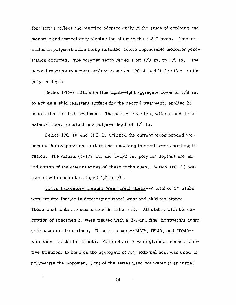
four series reflect the practice adopted early in the study of applying the
monomer and immediately placing the slabs in the 125"F oven. This re
sulted in polymerization being initiated before appreciable monomer pene
tration occurred. The polymer depth varied from 1/8 in. to 1/4 in. The
second reactive treatment applied to series 2PC-4 had little effect on the
polymer depth.
Series 1PC-7 utilized a fine lightweight aggregate cover of 1/8 in.
to act as a skid resistant surface for the second treatment, applied 24
hours after the first treatment. The heat of reaction, without additional
external heat, resulted in a polymer depth of 1/4 in.
Series 1PC-10 and 1PC-12 utilized the current recommended pro
cedures for evaporation barriers and a soaking interval before heat appli
cation. The results (1-1/8 in. and 1-1/2 in. polymer depths) are an
indication of the effectiveness of these techniques. Series 1PC-IO was
treated with each slab sloped 1/4 in./ft.
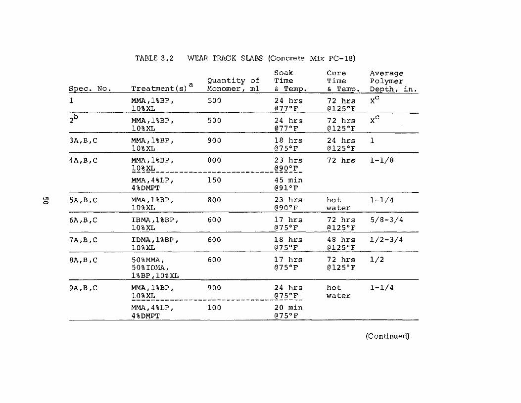
3.4.2 Laboratory Treated Wear Track Slabs--A total of 27 slabs
were treated for use in determining wheel wear and skid resistance.
These treatments are summarized in Table 3.2. All slabs, with the ex
ception of specimen 2, were treated with a l/4-in. fine lightweight aggre
gate cover on the surface. Three monomers-- MMA, IBMA, and IDMA-
were used for the treatments. Series 4 and 9 were given a second I reac
tive treatment to bond on the aggregate cover: external heat was used to
polymerize the monomer. Four of the series used hot water at an initial
49
U1 o
Spec. No.
1
3A,B,C
4A,B,C
5A,B,C
6A,B,C
7A,B,C
8A,B,C
9A,B,C
TABLE 3.2 WEAR TRACK SlABS (Concrete Mix PC-I8)
Treatment(s)a
MMA,l%BP, 10%XL
MMA, l%BP, 10%XL
MMA, l%BP, 10%XL
Quantity of Monomer, ml
500
500
900
Soak Time & Temp.
24 hrs @77°P
24 hrs @77°P
18 hrs @75°P
MMA,l%BP, 800 23 hrs
!Q~~-------------------------~~Q:~-MMA, 4%LP, 4%DMPT
MMA,l%BP, 10%XL
IBMA,l%BP, 10%XL
IDMA,l%BP, 10%XL
50%MMA, 50%IDMA, 1%BP,10%XL
150
800
600
600
600
45 min @91°P
23 hrs @90oP
17 hrs @75°P
18 hrs @75°P
MMA,l%BP, 900 24 hrs 10%XL @75°P ------------------------------------MMA, 4%LP, 4%DMPT
100 20 min @75°P
Cure Time & Temp.
72 hrs @125°P
72 hrs @125°P
24 hrs @125°P
72 hrs
hot water
72 hrs @125°P
48 hrs @125°P
72 hrs @125°P
hot water
Average Polymer Depth, in.
1
1-1/8
1-1/4
5/8-3/4
1/2-3/4
1/2
1-1/4
(Continued)
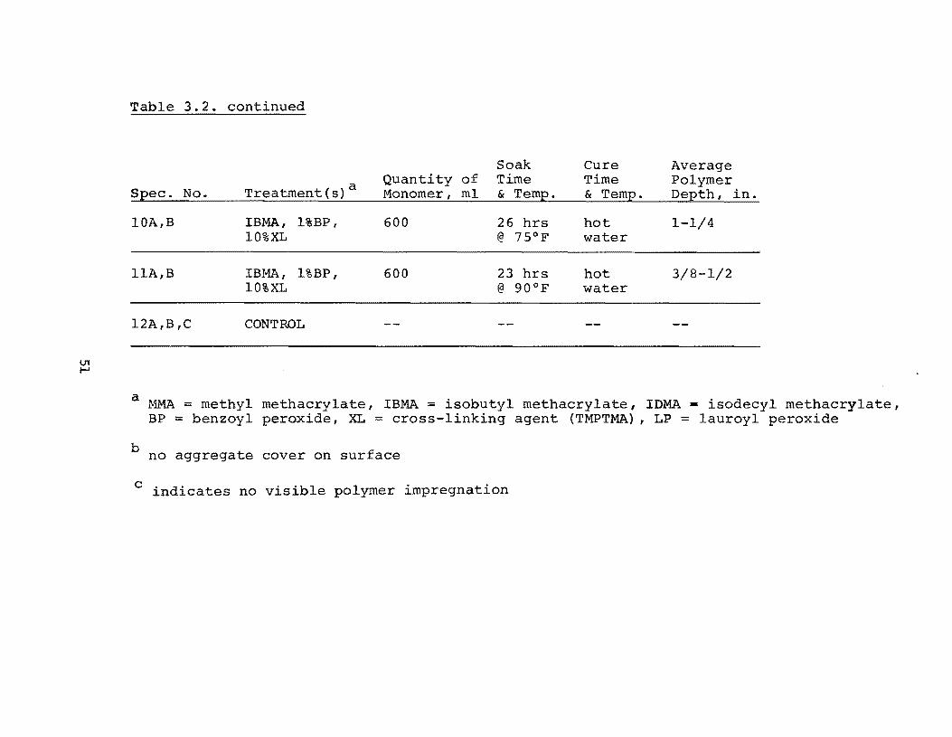
Table 3.2. continued
Soak Cure Average
Treatment(s)a Quantity of Time Time Polymer Monomer, ml & Temp. & Temp. Depth, in. Spec. No.
10A,B IBMA, l%BP, 600 26 hrs hot 1-1/4 10%XL @ 75°F water
llA,B IBMA, l%BP, 600 23 hrs hot 3/8-1/2 10%XL @ 90°F water
l2A,B,C CONTROL
a MMA = methyl methacrylate, IBMA = isobutyl methacrylate, IDMA - isodecyl methacrylate, BP = benzoyl peroxide, XL = cross-linking agent (TMPTMA), LP = lauroyl peroxide
b no aggregate cover on surface
c indicates no visible polymer impregnation
temperature of =212"P; all other slabs were cured in a 125°P oven. The
trapezoidal- shaped slabs were 2 in. thick.
With the exception of specimens 1 and 2 I all slabs had at least some
polymer impregnation. Slab 2 I which had no aggregate cover I apparently
lost all of the monomer due to evaporation during the long soak period.
There is no obvious explanation for the lack of polymer in slab 1.
Other than specimens 1 and 2, IDMA or IDMA and MMA had the
shallowest depths of polymer impregnation, ranging from 3/8 in. to 3/4 in.
The specimens treated with MMA developed polymer depths of 1 in. or
more.
3.4.3 Pield-Treated Slabs--To investigate the monomer application
and curing techniques under field conditions, twelve pairs of 5-1/2 x 40 x
43-in. slabs were cast and field-treated (Table 3.3). One reinforced
slab and one unreinforced slab comprised a pair. Reinforcement consisted
of No. 8 bars at 7-in. o. c. with one inch clear cover.
Mter curing for several months during the winter, the slabs were pre
dried with a heating blanket for a minimum of three days. In order to
simulate actual bridge conditions, the surfaces of all slabs were sloped
1/4 in./ft. During the drying and polymerization periods (March through
June) air temperatures ranged from 37°P to 95°P. The slabs were pro
tected from rain by polyethylene membrane.
Mter the slabs had been dried and permitted to cool to air tempera
ture, a l/4-in. dry lightweight fine aggregate cover was placed on each
52
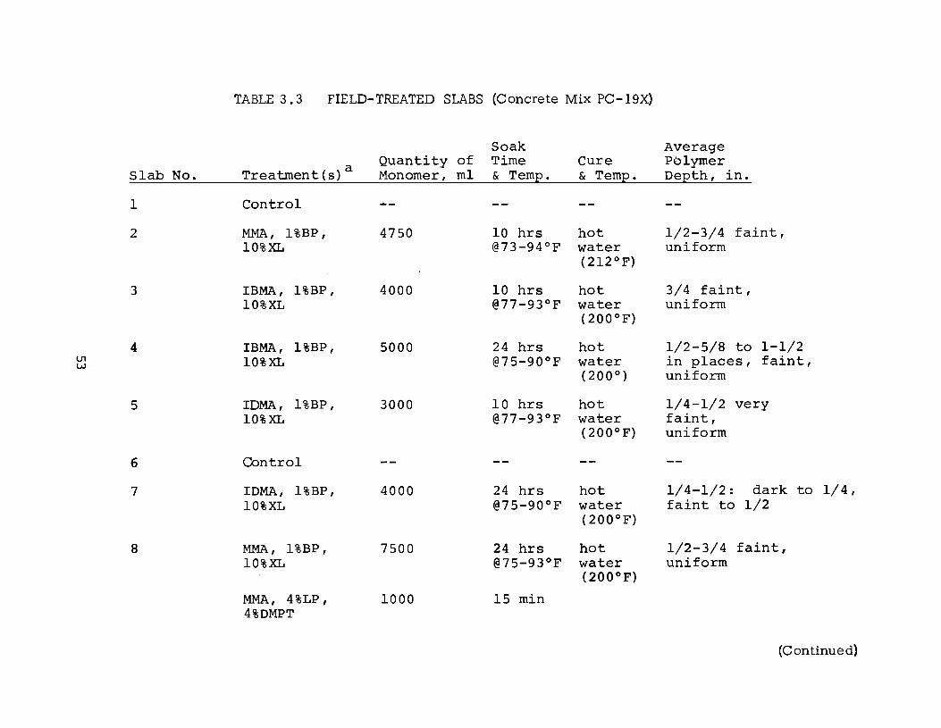
TABLE 3.3 FIELD-TREATED SLABS (Concrete Mix PC-19X)
Soak Average Quantity of Time Cure Pblymer a Slab No. Treatment{s) Monomer, ml & Temp. & Temp. Depth, in.
1 Control
2 MMA, l%BP, 4750 10 hrs hot 1/2-3/4 faint, 10%XL @73-94°P water uniform
(212°P)
3 IBMA, l%BP, 4000 10 hrs hot 3/4 faint, 10%XL @77-93°P water uniform
(200 0 P)
4 IBMA, l%BP, 5000 24 hrs hot 1/2-5/8 to 1-1/2 U1 10%XL @75-90oP water in places, faint, w
(200°) uniform
5 IDMA, l%BP, 3000 10 hrs hot 1/4-1/2 very 10%XL @77-93°P water faint,
(200 0 P) uniform
6 Control
7 IDMA, l%BP, 4000 24 hrs hot 1/4-1/2: dark to 1/4, 10%XL @75-90oP water faint to 1/2
(200 0 P)
8 MMA, l%BP, 7500 24 hrs hot 1/2-3/4 faint, 10%XL @75-93°P water uniform
(200 0 P)
MMA, 4%LP, 1000 15 min 4%DMPT
(Continued)
U1 ,j::.
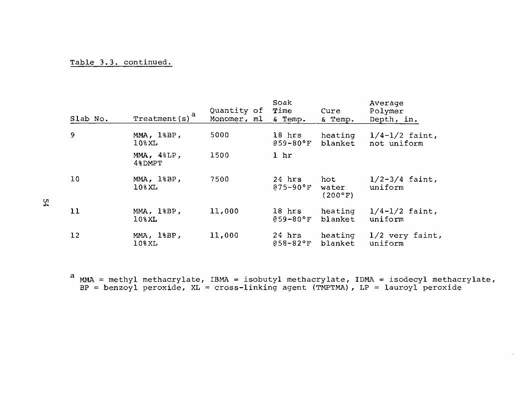
Table 3.3. continued.
Soak Average
a Quantity of Time Cure Polymer Slab No. Treatment(s) Monomer, ml & Temp. & Temp. Depth, in.
9 MAA, l%BP, 5000 18 hrs heating 1/4-1/2 faint, 10%XL @59-80oF blanket not uniform
MMA, 4%LP, 1500 1 hr 4%DMPT
10 MMA, l%BP, 7500 24 hrs hot 1/2-3/4 faint, 10%XL @75-90°F water uniform
(200°F)
11 MMA, l%BP, 11,000 18 hrs heating 1/4-1/2 faint, 10%XL @59-80°F blanket uniform
12 MMA, l%BP, 11,000 24 hrs heating 1/2 very faint, 10%XL @58-82°F blanket uniform
a MMA = methyl methacrylate, IBMA = isobutyl methacrylate, IDMA = isodecyl methacrylate, BP = benzoyl peroxide, XL = cross-linking agent (TMPTMA), LP = lauroyl peroxide
slab. The slab was then thoroughly wetted with the monomer system (Fig.
3.2). Periodic applications of monomer were made as required to keep the
aggregate moist. The aggregate was very effective in preventing monomer
run-off. The total monomer volume required for each slab ranged from
3000 ml to 11,000 m1 (Table 3.3). The slabs using IDMA, which had the
highest viscosity of the three monomers used, required only 3000 ml and
4000 ml, respectively. The slabs using IBMA required 4000 ml and 5000 m1,
respectively. Slabs using MMA, which had the lowest viscosity and was
the most volatile, required 4750 ml to 11,000 ml per slab. However, it
should be emphasized that liberal amounts of monomer were used and I for
some slabs I the soak time was as long as 18 or 24 hours, which resulted
in significant evaporation losses.
The first slabs treated were cured with heating blankets (Fig. 3.6).
However I the heating blankets required a relatively long period of time to
reach a slab temperature of 125°F. For example, when the blanket was
applied at 9:00 a.m., the slab temperature had only reached 105°F by late
afternoon (Fig. 3. 7) •
All of the later treatments were cured by hot water. Water was
heated to 200°F or higher in steel drums using gas heaters. The water
was placed on the slabs in shallow vats which consisted of polyethylene
membrane draped over the slab and a perimeter wood form (Fig. 3.11). A
minimum water depth of ::::::3 in. was maintained. Polyethylene membrane
and plywood were placed over the water vat to minimize the heat loss from
55
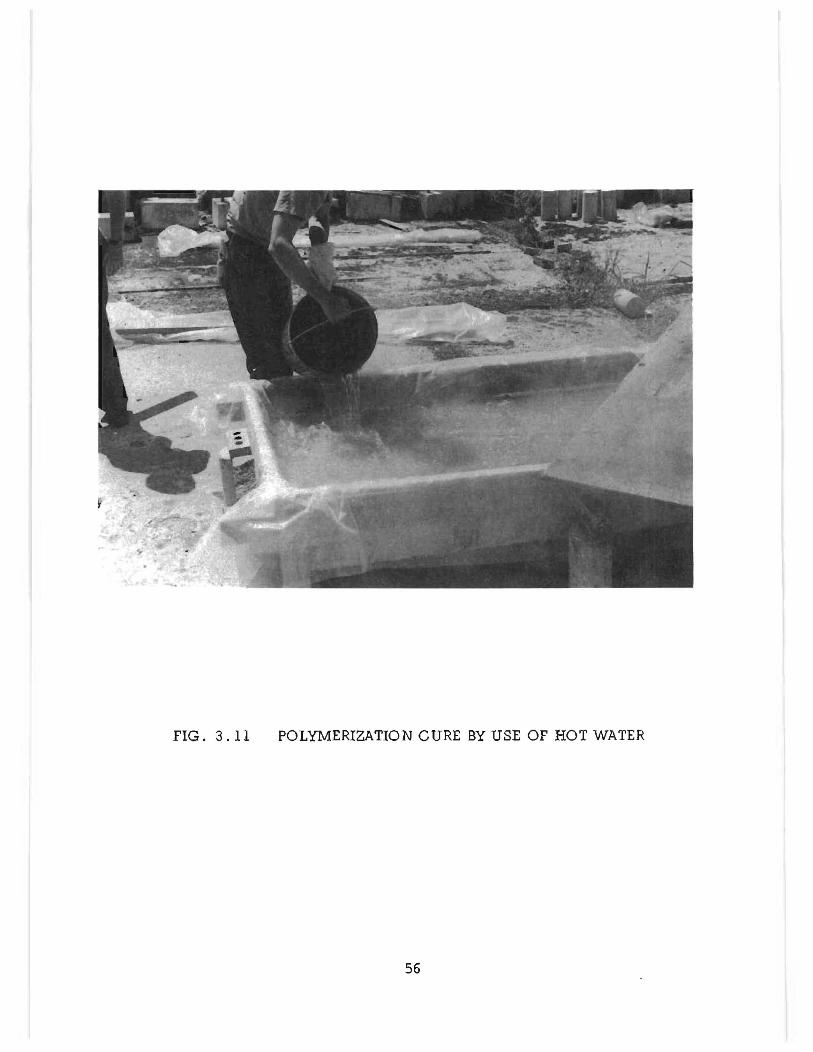
FIG. 3.11 POLYMERIZATION CURE BY USE OF HOT WATER
56
the water. Concrete surface temperature s of :::: 13 0° F were reached with air
temperatures of approximately 90°F.
Due primarily to the high quality concrete used in the construction of
the slabs I the monomer penetration was not as deep as usual. The result
ing polymer depths varied considerably and the impregnated zone was gen
erall y faint in color.
57

!!!!!!!!!!!!!!!!!!!"#$%!&'()!*)&+',)%!'-!$-.)-.$/-'++0!1+'-2!&'()!$-!.#)!/*$($-'+3!
44!5"6!7$1*'*0!8$($.$9'.$/-!")':!
CHAPTER 4.
Properties of Polymer-Impregnated Concrete
4.1 Pull-Impregnation Techniques
Ideally I it would be desirable to evaluate the properties in the surface
treated specimens I but there are no reliable tests to determine the mechan
ical properties for a thin layer of treated concrete which is monolithic with
plain concrete. To evaluate the mechanical properties of the polymer
impregnated surface I tests were performed on fully-impregnated concrete
specimens.
Tests on 3 x 7 in. cylinders and 3 x 3 x 14 in. beams were performed
to determine: (1) modulus of elasticity; (2) utlimate compressive stress;
(3) ultimate tensile stress; and (4) modulus of rupture. In all cases three
specimens were treated and tested to obtain an average value.
All specimens were moist-cured for seven days after which they were
air-dried until an age of 28 days had been attained.
4. 1. 1 Drying-- Before the specimens were impregnated I they were
subjected to an additional drying period of seven days in an oven to elimi
nate the free water in the pores. The drying temperature ranged from 125°P
to 220oP. After drying I and just prior to application of the vacuum the
59
specimens were removed from the oven and wrapped in polyethylene to
minimize absorption of moisture from the air until the concrete had cooled
to room temperature.
4. 1.2 Evacuation--Mter cooling I the specimens were unwrapped
and immediately placed in the vacuum chamber. A negative gauge pressure
of ::::27 in. Hg was maintained for a minimum of three hours. Previous
studies had shown that longer evacuation times failed to produce higher
polymer loadings.(24)
4.1.3 Monomer Soaking--Mter completion of the evacuation I the
monomer solution was injected into the container holding the specimens in
side the vacuum chamber. Mter the specimens were completely immersed
in the monomer I the vacuum was released I yielding an effective over-
pressure of ::127 in. Hg on the monomer to assist the impregnation.
A soak time of five hours for MMA had been found to be adequate (24)
to obtain full impregnation in conjunction with the three hour evacuation
time. For monomers having viscosities in excess of five centis tokes I the
soak time was increased to 15 hours.
4. 1.4 Curing--Upon completion of the soak period I the specimens
were removed from the monomer and immersed in a water bath to minimize
evaporation of the monomer. In the initial phase of the study the specimens
were first wrapped in polyethylene before being placed in the water. In
later treatments I the polyethylene was omitted since the monomers used are
essentially insoluable in water, and there was no discernible difference in
60
the polymer loading or strength. The water was maintained at a temperature
of ':::130°F for a minimum of 24 hours for MMA: all other monomers were
cured for 120 hours.
Later investigations indicated that much shorter cure times are ade
quate. Figure 4.1 indicates compressive strength versus cure time for MMA
at a water cure temperature of =130°F using three different concrete batches.
All specimens were 3 x 6 in. cylinders. It is apparent that six hours is
sufficient to cure the MMA. Styrene I the most difficult to cure of the mono
mers used in this study I required approximately 65 hours.
After curing, the specimens were placed in a 175° F oven for drying.
After drying I the specimens were cooled to room temperature before testing.
4.2 Compression Strength
All cylinders were tested in accordance with American Society for
Testing Materials (ASTM) specification C39. Control specimens consist
ing of untreated specimens were tested with each series of PIC specimens.
Table 4.1 summarizes the compression strength of a large number of
specimens impregnated with MMA. Some of the monomer solutions con
tained no TMPTMA while some used 10 percent and ,5 percent. The speci
mens without TMPTMA averaged 14,770 psi while specimens with 10 per
cent TMPTMA averaged 13,790 psi. The strength ratio, defined as the
ratio of treated specimen strength to control strength, ranged from 2.41 to
3.28.
61
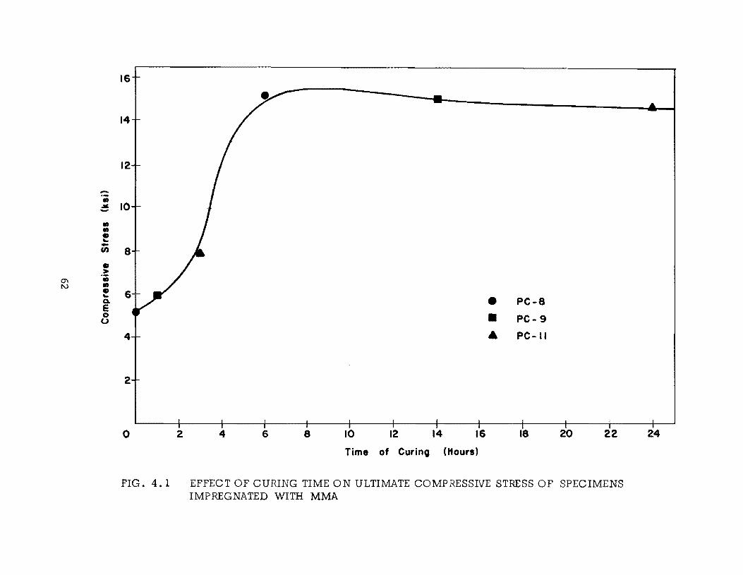
-• .. -• • • ... -(I) • >
0'\ • I\J • • ...
Q.
E 0 0
16
14
12
10
8
6 • PC-8
• PC-9
4 • PC-II
2
o 2 4 6 8 10 12 14 16 18 20 22
Time of Curing (Hours)
FIG. 4.1 EFFECT OF CURING TIME ON ULTIMATE COMPRESSIVE STRESS OF SPECIMENS IMPREGNATED WITH MMA
24
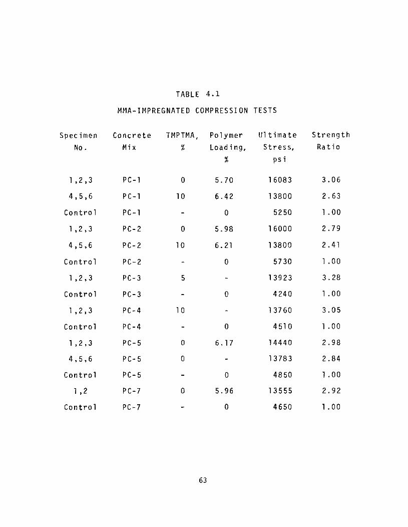
TABLE 4.1
MMA-IMPREGNATED COMPRESSION TESTS
Specimen Concrete TMPTMA , Po 1 ymer Ultimate Strength
No. Mix % Load i ng, Stress, Ra t i a
% psi
1 ,2 ,3 PC-l 0 5.70 16083 3.06
4,5,6 PC-l 10 6.42 13800 2.63
Control PC-l 0 5250 1.00
1 ,2,3 PC-2 0 5.98 16000 2.79
4,5,6 PC-2 10 6.21 13800 2.41
Control PC-2 0 5730 1.00
1 ,2,3 PC-3 5 13923 3.28
Control PC-3 0 4240 1.00
1 ,2,3 PC-4 10 13760 3.05
Control PC-4 0 4510 1 .00
1 ,2,3 PC-5 0 6.17 14440 2.98
4,5,6 PC- 5 0 13783 2.84
Control PC- 5 0 4850 1.00
1 ,2 PC-7 0 5.96 13555 2.92
Control PC-7 0 4650 1.00
63
Using similar monomer solutions I other investigators have found
higher strengths. This is due in all probability to lower polymer loading
in many of the specimens I perhaps as a result of lower drying temperatures.
Compressive strengths for several monomers are compared in Table
4.2. The specimens with s tearyl methacrylate I isobornyl methacrylate I and
high percentages of isodecyl methacrylate developed the lowest compres
sive strengths. The relatively low polymer loadings are due to the higher
viscosities of some of the monomers and due to the higher impermeability of
the concrete I which had a control strength of 6600 psi. The polymer load
ing can be observed to be dependent upon the monomer viscosity from
Fig. 4.2.
4.3 Moduli of Elasticity
The moduli of elasticity have been found for many of the monomers
evaluated in this investigation. The strains used to calculate the moduli
were obtained during the compression tests. The first of the three speci
mens was loaded to its ultimate load without the strain apparatus attached.
The strains were measured on the other two specimens by means of a dial
gauge extensometer with a 4 in. gauge length. The apparatus was removed
at 60 percent of the anticipated ultimate load to prevent damage to the
dial gauges.
Table 4.2 summarizes the moduli for different monomers. While the
modulus is increased for most monomers I the increase is not as great as for
compression strength.
64
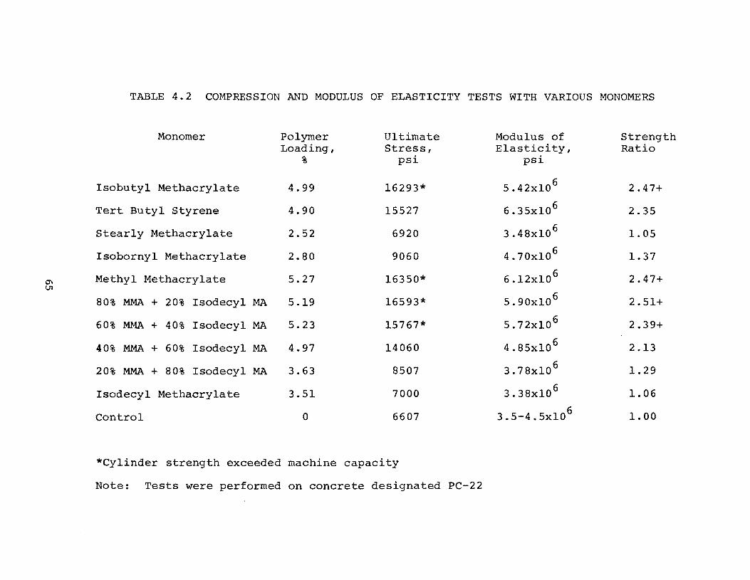
TABLE 4.2 COMPRESSION AND MODULUS OF ELASTICITY TESTS WITH VARIOUS MONOMERS
Monomer Polymer Ultimate Modulus of Strength Loading, Stress, Elasticity, Ratio
% psi psi
Isobutyl Methacrylate 4.99 16293* 5.42xl06 2.47+
Tert Butyl Styrene 4.90 15527 6.35xl06 2.35
Stearly Methacrylate 2.52 6920 3.48xl06 1.05
Isobornyl Methacrylate 2.80 9060 4.70x10 6 1.37
Methyl Methacrylate 5.27 16350* 6 2.47+ 0"1 6.l2xlO VI
80% MMA + 20% Isodecyl MA 5.19 16593* 5.90xl0 6 2.51+
60% MMA + 40% Isodecyl MA 5.23 15767* 5.72xl0 6 2.39+
40% MMA + 60% Isodecyl MA 4.97 14060 4.85xl0 6 2.13
20% MMA + 80% Isodecyl MA 3.63 8507 3.78xlO 6 1.29
Isodecyl Methacrylate 3.51 7000 3.38x10 6 1.06
Control 0 6607 3.5-4.5xlO 6 1.00
*Cylinder strength exceeded machine capacity
Note: Tests were performed on concrete designated PC-22
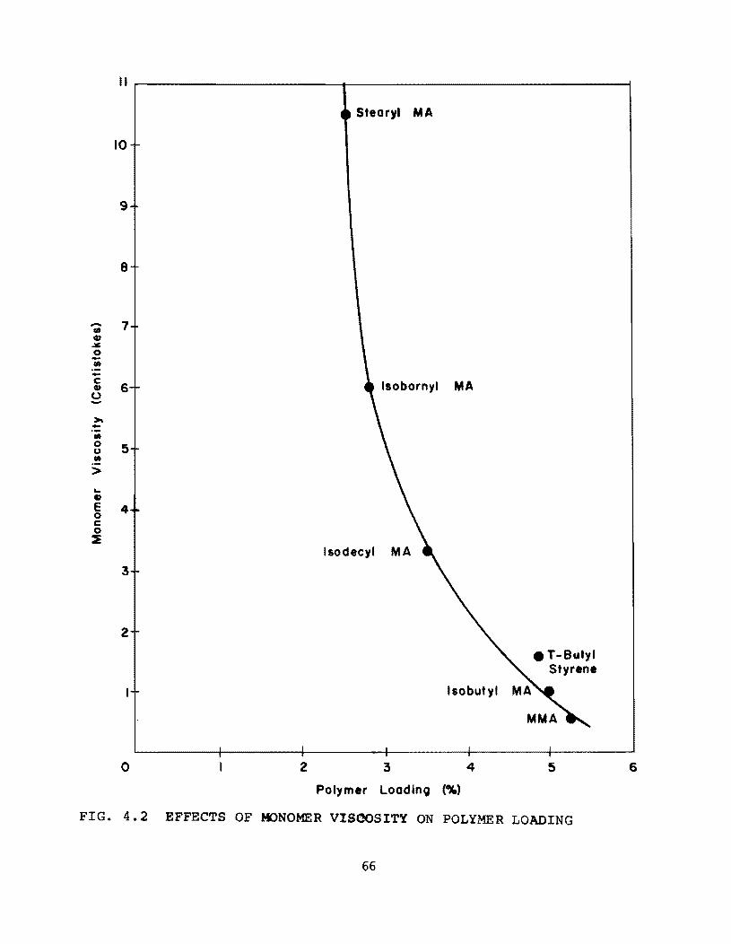
-(It CD ~ 0 -co -c CD 0 ->--co 0 u co > ~ ., E 0 c 0 ~
1I~------------------~---------------------------1
10
9
8
7
6
5
4
3
2
o 2
$tearyl MA
Isobornyl MA
Isodeeyl MA
Isobutyl
3 4
Polymer Loadino (%)
• T-Butyl Styrene
5 6
FIG. 4.2 EFFECTS OF MONOMER VISCOSITY ON POLYMER LOADING
66
4 .4 Moduli of Rupture
The moduli of rupture were obtained from flexural tests of 3 x 3 x
14-in. beams. The simply supported beams had a span of 12 in. and
were loaded at the third pOints. The tests were performed in general accord
ance with ASTM C78-64.
The impregnation procedure was similar to that used for cylinders. All
of the specimens contained 1 percent BP; the amount of TMPTMA was
varied from 0 to 10 percent. Some of the specimens had air entraining agents
added to the mix which yielded 5 percent air entrainment.
The results for specimens impregnated with MMA are shown in Table
4.3. It is interesting to note that the polymer loading increased slightly
with increasing cross-linking agent while the modulus of rupture decreased,
apparently because of the more brittle polymer produced with TMPTMA.
4.5 Tensile Strength
A limited number of 3 x 6-in. cylinders were tested in accordance with
ASTM C 466 to determine tensile strength. Table 4.4 summarizes these
tests. MMA-impregnated concrete developed a strength ratio of 2.06 com
pared to 2.71 for styrene-impregnated cylinders. All monomer solutions
used 1 % benzoyl peroxide catalyst.
67
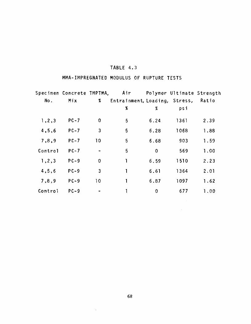
TABLE 4.3
MMA- H1PREGNATED MODULUS OF RUPTURE TESTS
Specimen Concrete TMPTMA, Air Polymer Ultimate Strength No. Mix % E n t r a ; n men t, Loa d ; n g, Stress, Ratio
% % psi
1 ,2,3 PC-7 0 5 6.24 1361 2.39
4,5,6 PC-7 3 5 6.28 1068 1.88
7,8,9 PC-7 10 5 6.68 903 1. 59
Control PC-7 5 0 569 1. 00
1 ,2,3 PC-9 0 1 6.59 1 510 2.23
4,5,6 PC-9 3 1 6.61 1364 2.01
7,8,9 PC-9 10 1 6.87 1097 1. 62
Control PC-9 1 0 677 1. 00
68
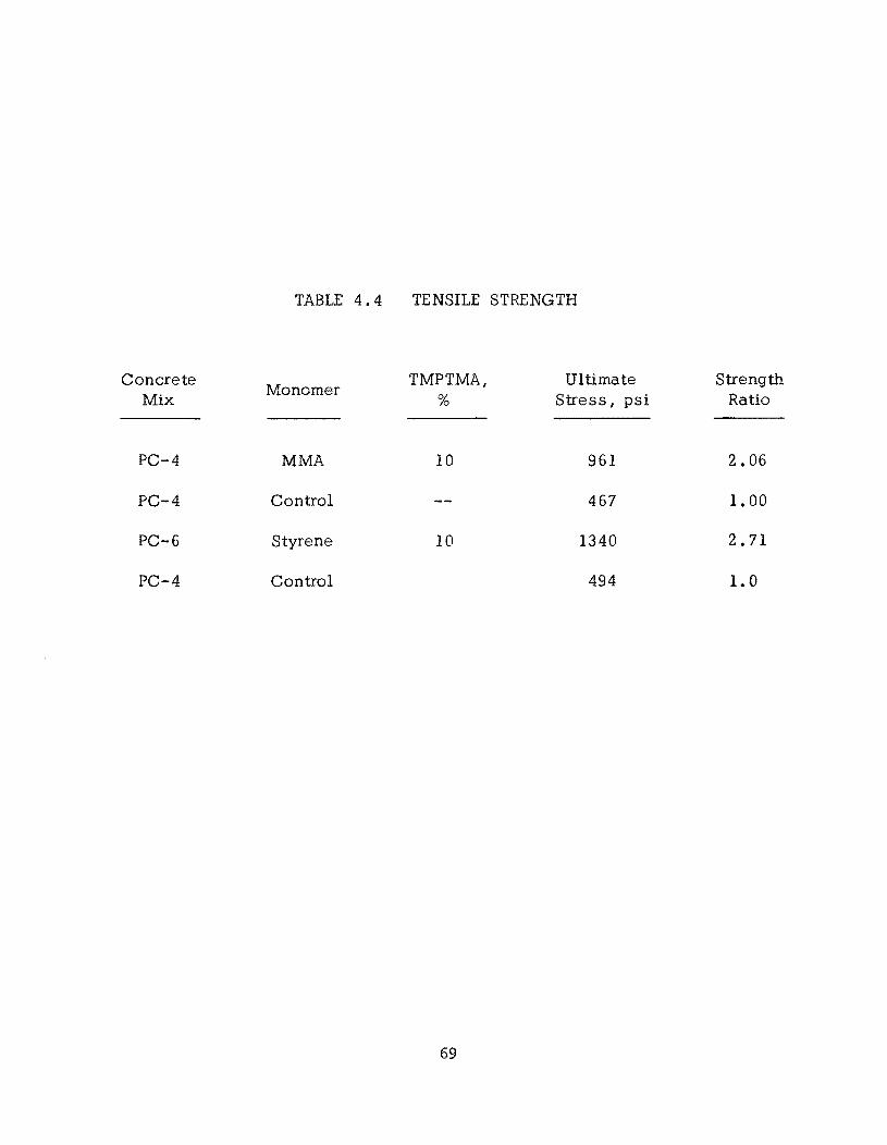
Concrete Mix
PC-4
PC-4
PC-6
PC-4
TABLE 4.4 TENSILE STRENGTH
Monomer
MMA
Control
Styrene
Control
TMPTMA, %
10
10
69
Ultimate Stress, psi
961
467
1340
494
Strength Ratio
2.06
1. 00
2.71
1.0

!!!!!!!!!!!!!!!!!!!"#$%!&'()!*)&+',)%!'-!$-.)-.$/-'++0!1+'-2!&'()!$-!.#)!/*$($-'+3!
44!5"6!7$1*'*0!8$($.$9'.$/-!")':!
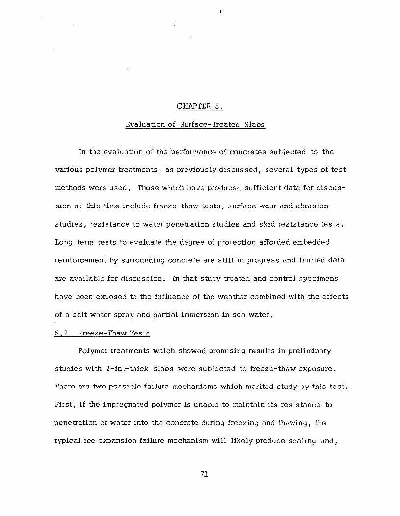
CHAPTER 5.
Evaluation of Surface-Treated Slabs
In the evaluation of the performance of concretes subjected to the
various polymer treatments, as previously discussed, several types of test
methods were used. Those which have produced sufficient data for discus
sion at this time include freeze-thaw tests, surface wear and abrasion
studies, resistance to water penetration studies and skid resistance tests.
Long term tests to evaluate the degree of protection afforded embedded
reinforcement by surrounding concrete are still in progress and limited data
are available for discussion. In that study treated and control specimens
have been exposed to the influence of the weather combined with the effects
of a salt water spray and partial immersion in sea water.
5. 1 Freeze-Thaw Tests
Polymer treatments which showed promising results in preliminary
studies with 2-in .-thick slabs were subjected to freeze-thaw exposure.
There are two possible failure mechanisms which merited study by this test.
First, if the impregnated polymer is unable to maintain its resistance to
penetration of water into the concrete during freezing and thawing, the
typical ice expansion failure mechanism will likely produce scaling and,
71
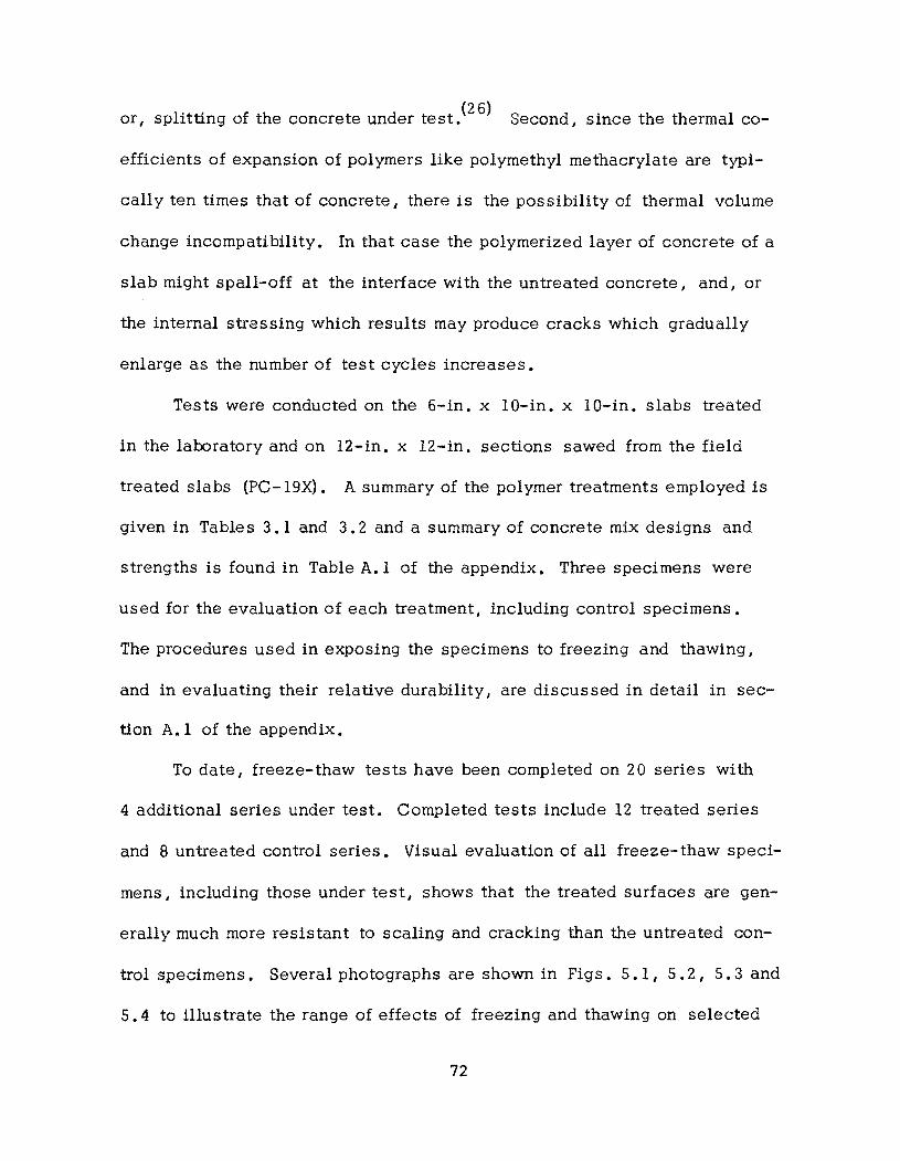
or, splitting of the concrete under test.(26) Second, since the thermal co
efficients of expansion of polymers like polymethyl methacrylate are typi
cally ten times that of concrete, there is the possibility of thermal volume
change incompatibility. In that case the polymerized layer of concrete of a
slab might spall-off at the interface with the untreated concrete, and, or
the internal stressing which results may produce cracks which gradually
enlarge as the number of test cycles increases.
Tests were conducted on the 6-in. x IO-in. x IO-in. slabs treated
in the laboratory and on 12-in. x 12-in. sections sawed from the field
treated slabs (PC-19X). A summary of the polymer treatments employed is
given in Tables 3.1 and 3.2 and a summary of concrete mix designs and
strengths is found in Table A.I of the appendix. Three specimens were
used for the evaluation of each treatment, including control specimens.
The procedures used in exposing the specimens to freezing and thawing I
and in evaluating their relative durability I are discussed in detail in sec
tion A.l of the appendix.
To date, freeze-thaw tests have been completed on 20 series with
4 additional series under test. Completed tests include 12 treated series
and 8 untreated control series. Visual evaluation of all freeze-thaw speci
mens, including those under test, shows that the treated surfaces are gen
erally much more resistant to scaling and cracking than the untreated con
trol specimens. Several photographs are shown in Figs. 5.1, 5.2, 5.3 and
5.4 to illustrate the range of effects of freezing and thawing on selected
72
FIG. 5.1 AIR ENTRAINED CONTROL SLAB AT ZERO AND 120 CYCLES OF FREEZE-THAW TESTING (PC-7-CONTROL)
73
FIG. 5.2 MMA LAB TREATED SLAB AT ZERO AND 100 CYCLES OF FREEZE-THAW TESTING (PC-J)
74
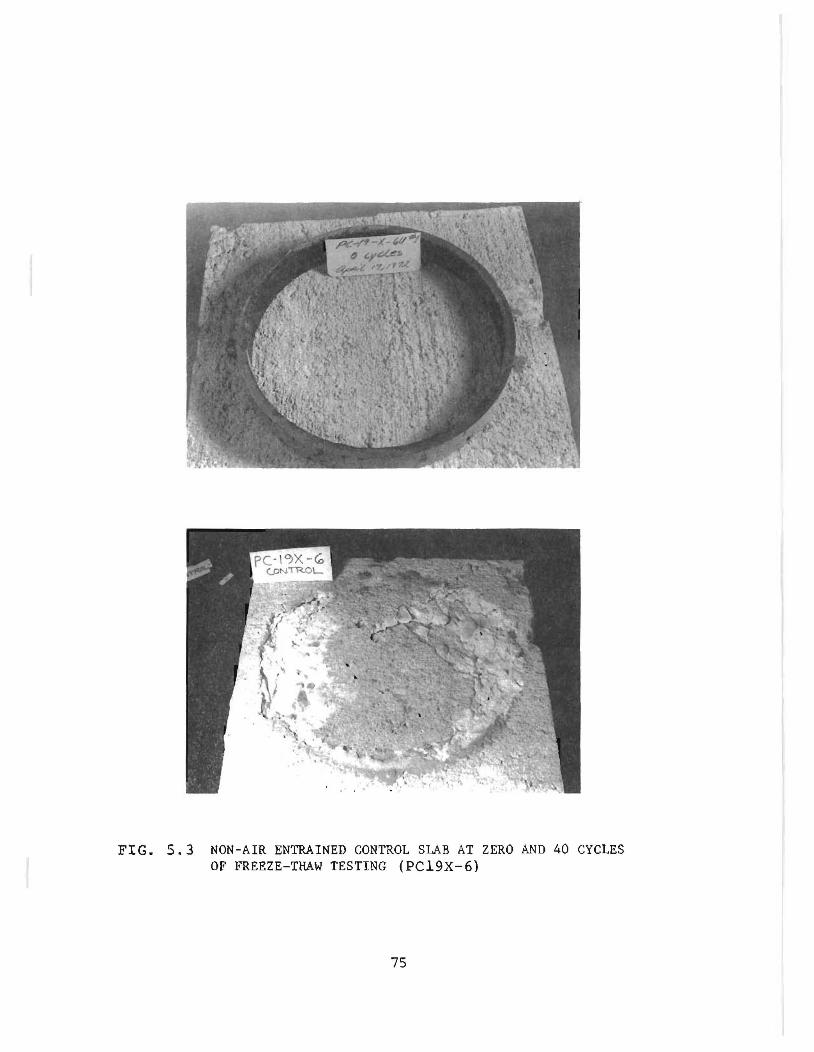
FIG. 5.3 NON-AIR ENTRAINED CONTROL SLAB AT ZERO AND 40 CYCLES OF FREEZE-THAW TESTING (PC19X-6)
75
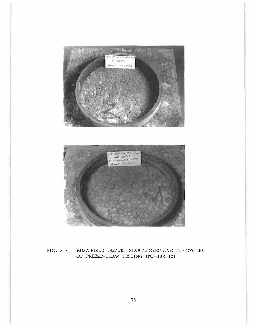
FIG. 5.4 MMA FIELD TREATED SLAB AT ZERO AND 120 CYCLES OF FREEZE-THAW TESTING (PC-19X-12)
76
specimens treated in the laboratory and field. The moderate scale of the
specimen in Fig. 5.1 after 120 test cycles is typical for the air-entrained
control concrete specimens. Also I no severe cracking was observed in the
air-entrained concretes through 120 test cycles ,although localized pitting
of the surfaces from 1/4 to 3/8 in. depths was typical.
Although the &caling seen in Fig. S. 1 might not be clas sed as severe I
it can be seen in Fig. 5.2 that the polymer treatment of the same concrete
mix has almost totally protected the exposed surface from freeze-thaw dam
age through 100 cycles. The light areas seen within the metal ring in both
photos of Fig. 5.2 are the bare concrete surface exposed when a portion of
the lightweight aggregate topping did not initially bond to the top of the
specimen. Close examination of these areas revealed that no change in the
exposed concrete could be detected through 120 cycles of freezing and thaw
ing. Furthermore I very few of the aggregate particles of the lightweight
topping were broken free as a result of 120 cycles of freeze-thaw exposure.
A similar comparison for the non-air-entrained concrete of the field
treatment series is given in Figs. 5.3 and 5.4. Note in Fig. 5.3 that the
non-air-entrained control specimens had badly deteriorated by severe crack
ing after only 40 cycles of test. On the other hand I the field application of
MMA with subsequent cure by heating blanket (treatment of PC-19X-12)
furnished complete protection of the specimen through 120 cycles of test as
shown in Fig. 5.4. Note in Fig. 5.4 that the thin layer of unintentionally
bonded , lightweight fine aggregate has remained essentially unaffected by
77
the freeze-thaw exposure.
By use of the mechanical strain gauge readings I as described in
Appendix A. I, the specimens were compared with regard to the contraction
occurring at the top and bottom of the slabs during the first freeze cycle. If
the polymer treated slabs are compared as a group to the control specimens I
the data show that polymer impregnation has resulted in greater contraction
in the upper half of the specimen. For example I calculations of the con
traction upon first freeze show that in 40 of 42 treated specimens, the top
strain exceeded the bottom strain by an average of 65 I.l in ./in., i. e., tops
of specimens exhibited the greater contraction. By comparison, for the con
trol series only in 8 of 17 specimens did the top strain exceed that of the
bottom. Furthermore I if a general trend for the control specimens is con
sidered, the net effect is that the average control specimen exhibited
approximately 5 I.l in ./in. greater contraction in the bottom half of the slab.
If the field treated specimens (PC-19X) are considered as a separate group,
the same trends are noted, with control specimens averaging zero strain
differential while eight of the treated series averaged 45 f.l in./in. greater
top contraction. It is of interest to note that the remaining two treated
series of PC-19X (numbers 8 and 9) exhibited 120 I.l in./in. greater top con
traction. The reason for the greater strain differential shown by the latter
two series was most probably the presence of the polymer in the l/4-in.
thick layer of intentionally bonded, lightweight fine aggregate.
Although a photographic record was made of each specimen throughout
78
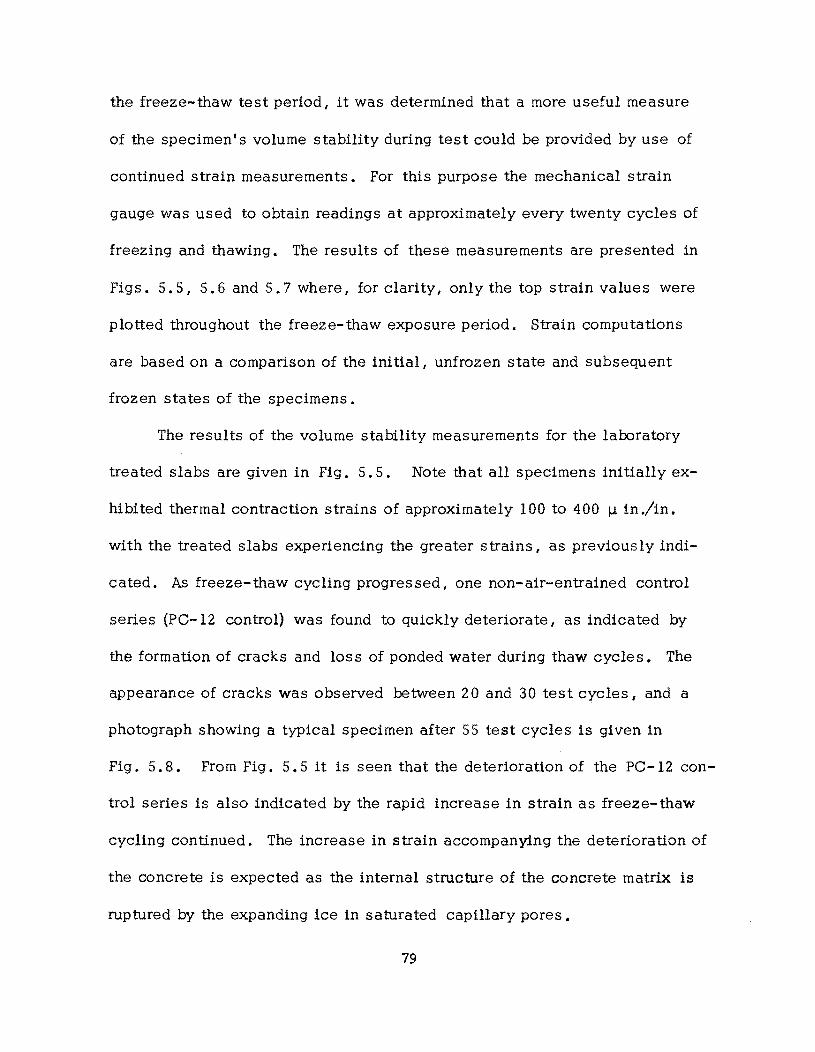
the freeze-thaw test period, it was determined that a more useful measure
of the specimen I s volume stability during test could be provided by use of
continued strain measurements. For this purpose the mechanical strain
gauge was used to obtain readings at approximately every twenty cycles of
freezing and thawing. The results of these measurements are presented in
Figs. 5.5, 5.6 and 5.7 where, for clarity, only the top strain values were
plotted throughout the freeze-thaw exposure period. Strain computations
are based on a comparison of the initial, unfrozen state and subsequent
frozen states of the specimens.
The results of the volume stability measurements for the laboratory
treated slabs are given in Fig. 5.5. Note that all specimens initially ex
hibited thermal contraction strains of approximately 100 to 400 ~ in./in.
with the treated slabs experiencing the greater strains, as previously indi
cated. As freeze-thaw cycling progressed, one non-air-entrained control
series (PC-12 control) was found to quickly deteriorate, as indicated by
the formation of cracks and loss of ponded water during thaw cycles. The
appearance of cracks was observed between 20 and 30 test cycles, and a
photograph showing a typical specimen after 55 test cycles is given in
Fig. 5.8. From Fig. 5.5 it is seen that the deterioration of the PC-12 con
trol series is also indicated by the rapid increase in strain as freeze-thaw
cycling continued. The increase in strain accompanying the deterioration of
the concrete is expected as the internal structure of the concrete matrix is
ruptured by the expanding ice in saturated capillary pores.
79
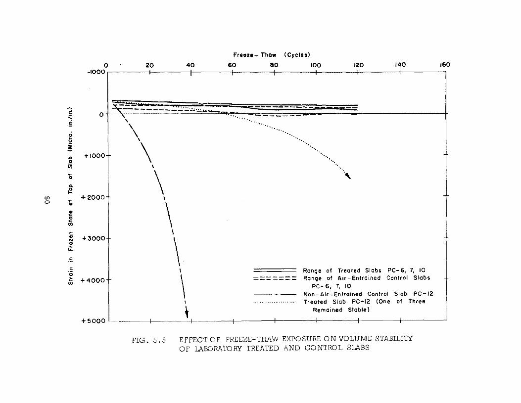
.-
.~ ..... c
0 .. u i ~
J:I 0 r.;; -0
Q.
F!-0:> 0 -0
• -0 -(f.) c:: • N 0
..t c::
c:: 0 .. -(f.)
Freeze - Thaw (Cycles)
140 o 20 40 60 80 100 120 160 -100°r--------+--------t-1-------t-1-------t,--------~------_4--------4_--------~
t~~=~~~~-~-~·~~IU~.~.~.~~~~~~~::~~~~====~~~--------------1 -,_______ • .. P ........... - = ---------- ::zr-r-o " ...... ---... --_
'.. ..,. ~ .
+1000
+2000
+3000
+4000
".
\ ....... .
'" ~ ......... ' .
'. ""l>. \
\ \
\ \
\ \
\ \
\ --------------
" . .... ". .........
....... ,
Range of Treated Slobs PC-6, 7, 10 Range of Air - Entrained Control Slabs
PC- 6, 7, 10 Non-Air-Entrained Control Slab PC-12 Treated Slob PC-12 (One of Three
, Remained Stable)
+5000 ~ __ ------~--------t-·----____ +---------+---------4:--------~,----------~---------1
FIG. 5.5 EFFECT OF FREEZE-THAW EXPOSURE ON VOLUME STABILIlY OF LABORATORY TREATED AND CONTROL SLABS
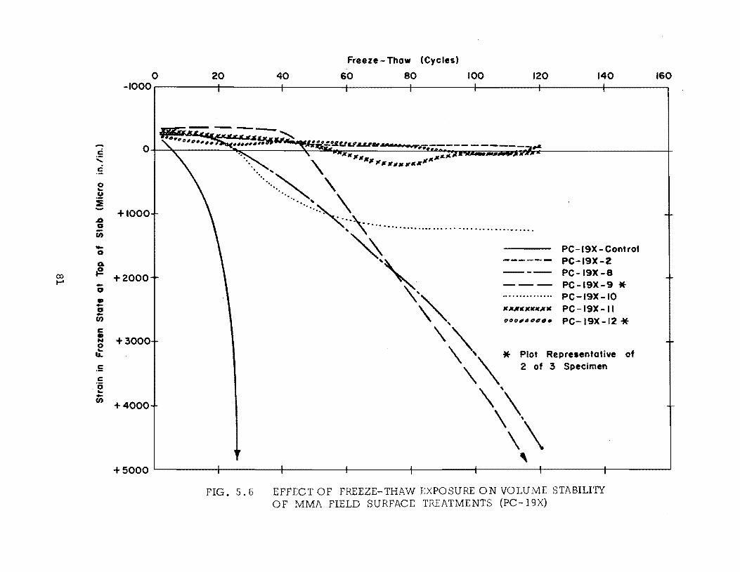
c ;;:: c 0 ... . 2 :e ..... .0 G U) -0
Go
co (l I-' -G
• -G -U)
c::: • N 0 ... IL
.5 c::: '0 ... -U)
Freeze - Thaw (Cycles)
20 o 60 80 100 160 140 40 120 -1000r--------r------~r_------~------_1--------4_------_;--------4_------~
+1000
+2000
+3000
+4000
...... ... '\ ...... ~ "
······~0 .:.\ ......................................... . ~
"
'\' "', If Itllfllttllt IUt.
PC-19X-Control PC-19X-2 PC-19X -8 PC-19X-9 * PC-19X-10 PC-19X-11 PC-19X-12 *
\ ~\'\ * Plot Representative of 2 of 3 Specimen
\' \\ \\ ,
+5000L--------r------~~------~------r-r-------~------r-r-------~------~
FIG. 5.6 EFFECT OF FREEZE-THAW EXPOSURE ON VOLUME STABILI'lY OF MMA FIELD SURFACE TR.I:ATMENTS (PC-19X)
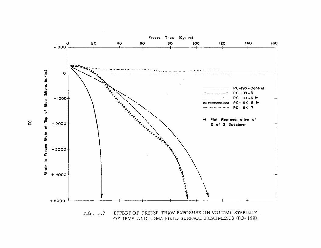
....
. 5 , c 0 ... CJ
:i ~
..c !a (I) -0
Q.
co {!. N -0
.! 0
Ui c CI) N 0 ...
LL
C
C
0 ... -(I)
Freeze - Thaw (Cycles)
20 60 80 100 120 140 o -1000r-------~------~------~--------_+--------~------~------~--------_,
160 40
+1000
+2000
+3000
+ 4000
+ 5000
FIG. 5.7
PC-19X- Control PC-19X-3 PC-19X-4 * PC-19X-5 * PC-19X-7
* Plot Representative of 2 of 3 Specimen
EFFECT OF FREEZE-THAW EXPOSURE ON VOLUME STABIliTY OF IBMA AND IDMA FIELD SURFACE TREATMENTS (PC-19X)
t
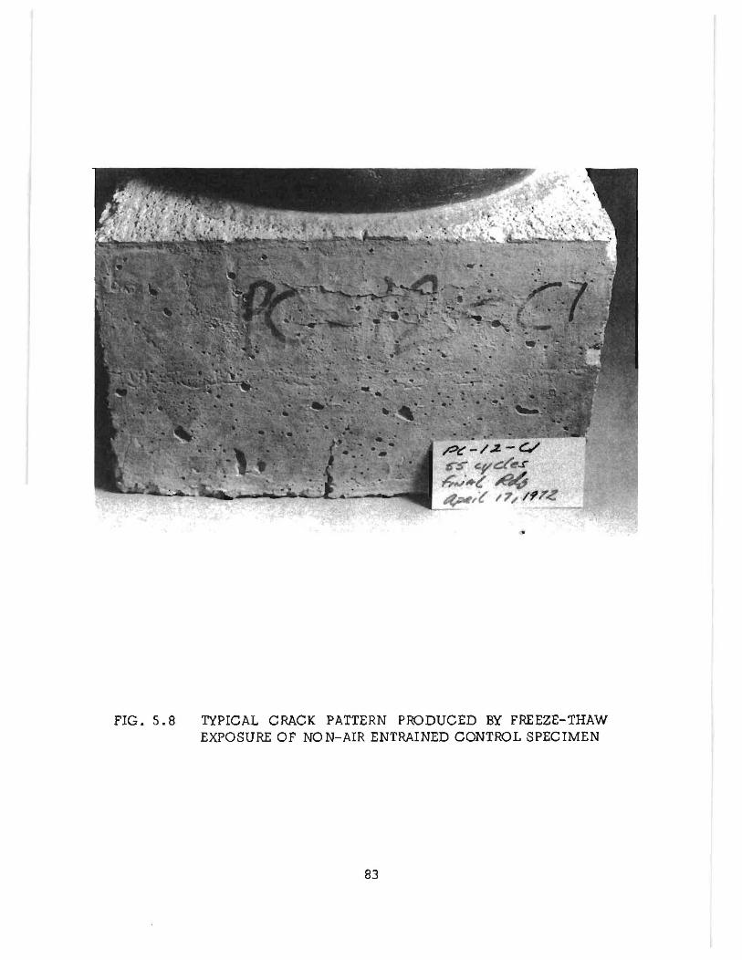
FIG. 5.8 TYPICAL CRACK PATTERN PRODUCED BY FREEZE-THAW EXPOSURE OF NON-AIR ENTRAINED CONTROL SPECIMEN
83
The next concrete to show signs of distress in Fig. 5.5 is the MMA
treated series PC-12. Within that group two specimens exhibited moderate
cracking and water loss at 60 and 100 cycles respectively and a third speci
men completed 12 a test cycles in good condition. The curve shown in Fig.
5.5 corresponds to the average strain of the two failing specimens and
again correlates well with the observed deterioration of the specimens.
All other test series given in Fig. 5.5 are seen to have maintained
relatively stable volume throughout the test period. Visual observation de
tected no cracking in these specimens although moderate surface scaling
was noted in all control concretes (see Fig. 5.1).
From the data of Fig. 5.5 it is apparent that for the non-air-entrained
concrete I polymer impregnation of the slab surfaces did extend the life of
the specimens under these relatively severe test conditions. Also I some
what unexpectedly I air-entrained control concretes are shown to compare
favorably with surface impregnated specimens in regard to volume stability.
However I some beneficial effects from surface impregnation were noted in
somewhat greater resistance to surface scaling.
The volume stability curves for the field treated test series (PC-19X)
are given in Figs. 5.6 and 5.7. The average of six control specimens is
repeated in both figures and all MMA treated specimens are given in Fig.
5.6 while those of IBMA and IDMA are shown in Fig. 5.7 for reasons of
convenience only.
In the analysis of the data of Fig. 5.6, it is helpful to review the
84
treatment methods used I as given in Table 3.3. From Table 3.3 note that
the MMA treatments can be grouped in pairs as follows: 2 and 10 I 8 and 9 I
and 11 and 12. Although this grouping does not represent duplication of
treatments I the treatments are sufficiently similar for such consideration
here.
As was the case in Fig. 5.5 I the non-air-entrained control specimens
of Fig. 5.6 displayed more rapid deterioration than any treated series.
Considerable cracking and water loss were noted in the control specimen
at 20 to 25 cycles of test. As observed previously I failure of the control
specimens was accompanied by rapidly increasing top strain as shown in
Fig. 5.6.
The least durable treated slabs of Fig. 5.6 as indicated by volume
instabili ty are those of series 8 and 9 I which were characterized by the
intentionally bonded layer of lightweight fine aggregate. Visual observa
tion revealed that cracks first appeared at 60 to 70 cycles in both series
and moderate water leakage occurred at approximately 80 cycles of test.
A factor which may have contributed to the early failure of these specimens
is the thermal volume change incompatibility of the bonded layer and sur
face concrete. This mechanism is suspect in view of the particularly high
differential strains exhibited by the specimens of these two series I as
previously mentioned.
A comparison of series 2 and lOin Fig. 5.6 indicates that, in spite
of a greater quanti ty of monomer and longer soak time during treatment,
85
series 10 exhibited somewhat less durable concrete compared to that of
series 2. In all respects the series 2 specimens are in very good condi
tion through 95 test cycles and these specimens were still in test at the
time this report was being written. Although the series 10 concrete dis
played an expansive strain slightly in excess of 1000 i.J. in./in. at 55 test
cycles, the top strain stabilized for the remainder of the test period, with
moderate cracking and moderate water loss being noted during that period.
Again, an important indication in the comparison of these two series is that
the freeze-thaw durability of the concrete was not a simple function of the
quantity of monomer and length of soak time used.
Finally, series 11 and 12 specimens of Fig. 5.6 displayed relatively
stable volume through 120 cycles of test, with no cracking and 11 ttle water
loss observed. An exception to this behavior was noted for one specimen
of series 12 which failed very rapidly at 95 cycles and was not included
when the average trend was drawn, as shown in Fig. 5. 6.
The freeze-thaw stability characteristics of the field treated IBMA
and IDMA slabs are shown in Fig. 5.7. From the standpoint of similarity
in treatment the series may be grouped in pairs, 3 and 4 (IBMA) and 5 and
7 (IDMA).
In Fig. 5.7 both IBMA treatments (3 and 4) are shown to lose volume
stability progressibely during testing. Visual observations revealed that
specimen cracking developed at 40 to 45 cycles in series 3 and at 60 to 65
cycles in series 4. Some loss of ponded water was noted shortly after the
86
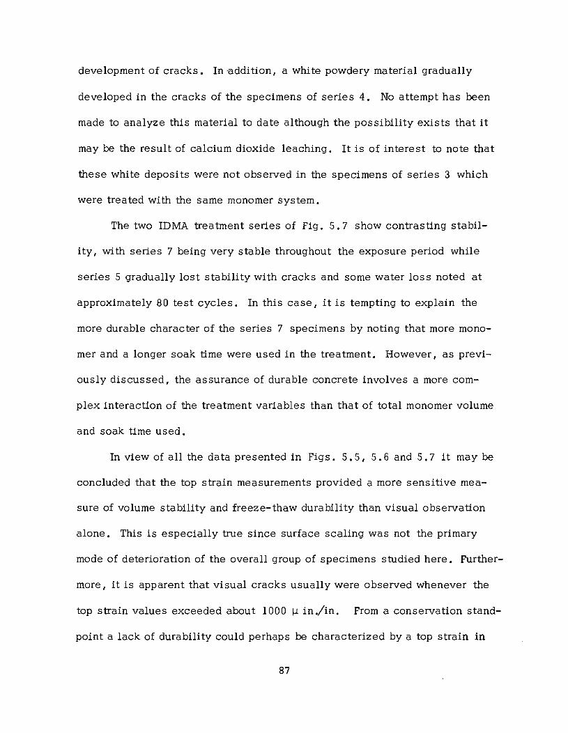
development of cracks. In -addition, a white powdery material gradually
developed in the cracks of the specimens of series 4. No attempt has been
made to analyze this material to date although the possibility exists that it
may be the result of calcium dioxide leaching. It is of interest to note that
these white deposits were not observed in the specimens of series 3 which
were treated with the same monomer system.
The two IDMA treatment series of Fig. 5.7 show contrasting stabil
ity, with series 7 being very stable throughout the exposure period while
series 5 gradually lost stability with cracks and some water loss noted at
approximately 80 test cycles. In this case, it is tempting to explain the
more durable character of the series 7 specimens by noting that more mono
mer and a longer soak time were used in the treatment. However, as previ
ously discussed, the assurance of durable concrete involves a more com
plex interaction of the treatment variables than that of total monomer volume
and soak time used.
In view of all the data presented in Figs. 5.5, 5.6 and 5.7 it may be
concluded that the top strain measurements provided a more sensitive mea
sure of volume stability and freeze-thaw durability than visual observation
alone. This is especially true since surface scaling was not the primary
mode of deterioration of the overall group of specimens studied here. Further
more, it is apparent that visual cracks usually were observed whenever the
top strain values exceeded about 1000 I-l in./in. From a conservation stand
point a lack of durability could perhaps be characterized by a top strain in
87
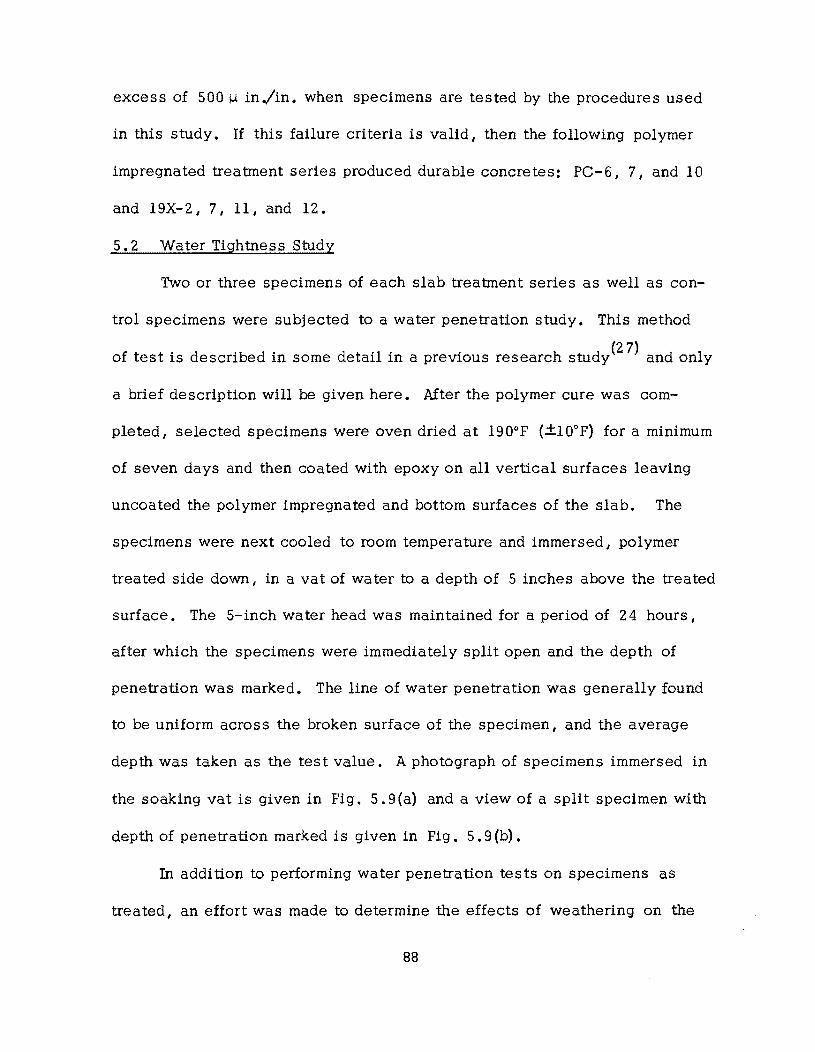
excess of 500 IJ. in./in. when specimens are tested by the procedures used
in this study. If this failure criteria is valid, then the following polymer
impregnated treatment series produced durable concretes: PC-6, 7, and 10
and 19X-2, 7, 11, and 12.
5.2 Water Tightness Study
Two or three specimens of each slab treatment series as well as con
trol specimens were subjected to a water penetration study. This method
of test is described in some detail in a previous research study(27) and only
a brief description will be given here. After the polymer cure was com
pleted, selected specimens were oven dried at 190°F (+10°F) for a minimum
of seven days and then coated with epoxy on all vertical surfaces leaving
uncoated the polymer impregnated and bottom surfaces of the slab. The
specimens were next cooled to room temperature and immersed, polymer
treated side down, in a vat of water to a depth of 5 inches above the treated
surface. The 5- inch water head was maintained for a period of 24 hours,
after which the specimens were immediately split open and the depth of
penetration was marked. The line of water penetration was generally found
to be uniform across the broken surface of the specimen, and the average
depth was taken as the test value. A photograph of specimens immersed in
the soaking vat is given in Fig. 5. 9(a) and a view of a split specimen with
depth of penetration marked is given in Fig. 5.9 (b) •
In addition to performing water penetration tests on specimens as
treated, an effort was made to determine the effects of weathering on the
88
ne;. 5.'
"
water tightness of the various polymer impregnated concretes. This was
accomplished by subjecting to the water penetration test those specimens
which had previously been used in the freeze-thaw study. Only the very
severely deteriorated freeze-thaw specimens were not used in the penetra-
tion study.
The results of the water penetration study are shown in Figs. 5.10
and 5.11 where a comparison of penetration before and after freeze-thaw
of both treated and untreated control concretes is given. It is of interest
first to consider the general behavior of all the control concretes. For
example, the non-air-entrained control concretes,* PC-12 and PC-19X,
are found to have greater penetration values both before and after freeze-
thaw exposure than those of the air-entrained mixes, PC-3, 4, 6, 7 and
10. These comparisons are in agreement with generally accepted trends
relating such mix properties as water-cement ratio and air content to con-
crete permeability. It should also be noted that the increase in penetra-
tion after freeze-thaw is much greater for the non-air-entrained control
concretes than for the air-entrained specimens. This is indicative of the
beneficial effects of air-entrainment on the freeze-thaw durability of
concrete.
In Fig. 5.10 all polymer impregnated concretes are seen to exhibit
less penetration than their companion control specimens, and those of
*Mix properties of all concretes are given in Table A.I of the appendix.
90
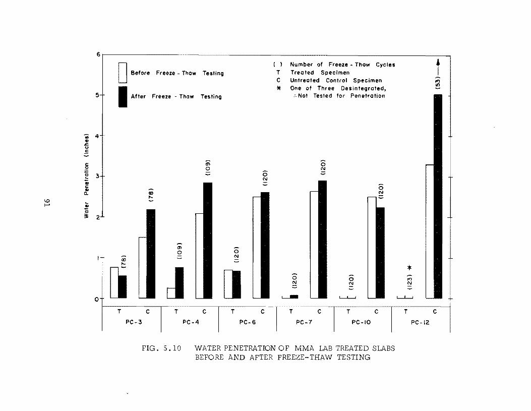
6
5
-;; 4 4J .c u .5
c ~ c 3 !: 4J C 4J a..
1.0 ... f-' .!!
c 3:: 2
0
DB •.• ," ( ) Number of Freeze - Thaw Cycles Freeze - Thow Testing T Treated Specimen
C Untreated Control Specimen
I .ft., * One of Three De s in tegrated, Freeze - Thaw Testing :. Not Tested for Penetration
-- --en 0 0 N
0 N
.-0
CD N ,....
cn 0 0 -- N
CD -,.... ~
[j [] 0 --0 N N
~ L........L.....
-[ T T C T C T C T C T C
PC-3 PC-4 PC-6 PC-7 PC-IO
FIG. 5. 10 WATER PENETRATION OF MMA lAB TREATED SlABS BEFORE AND AFTER FREEZE-THAW TESTING
t --", It)
* ", N
L-1.......J +
:
T C
PC-12
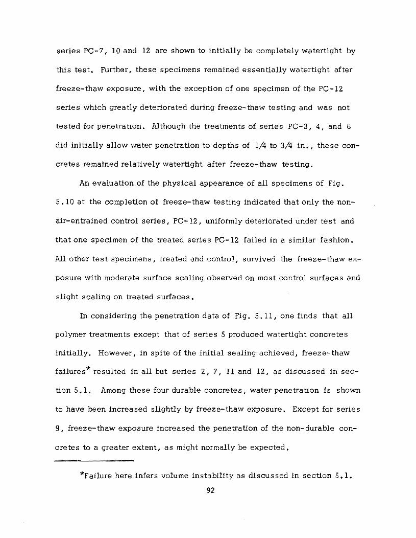
series PC-7, 10 and 12 are shown to initially be completely watertight by
this test. Further, these specimens remained essentially watertight after
freeze-thaw exposure, with the exception of one specimen of the PC-12
series which greatly deteriorated during freeze-thaw testing and was not
tested for penetration. Although the treatments of series PC-3, 4, and 6
did initially allow water penetration to depths of 1/4 to 3/4 in., these con
cretes remained relatively watertight after freeze-thaw testing.
An evaluation of the physical appearance of all specimens of Fig.
5. 10 at the completion of freeze-thaw testing indicated that only the non
air-entrained control series, PC-12, uniformly deteriorated under test and
that one specimen of the treated series PC-12 failed in a similar fashion.
All other test specimens, treated and control, survived the freeze-thaw ex
posure with moderate surface scaling observed on most control surfaces and
slight scaling on treated surfaces.
In considering the penetration data of Fig. 5. II, one finds that all
polymer treatments except that of series 5 produced watertight concretes
initially. However, in spite of the initial sealing achieved, freeze-thaw
failures* resulted in all but series 2, 7, 11 and 12, as discussed in sec
tion 5.1. Among these four durable concretes I water penetration is shown
to have been increased slightly by freeze-thaw exposure. Except for series
9, freeze-thaw exposure increased the penetration of the non-durable con
cretes to a greater extent, as might normally be expected.
*Failure here infers volume instability as discussed in section 5.1.
92
The behavior of the concrete of series 9 as well as that of the treated
specimens of series PC-12 in Fig. 5.10 may be of some importance here.
These specimens were found to be initially watertight and, in fact, remained
essentially watertight after freeze-thaw exposure. Yet, in spite of the
rather effective sealing of the specimens, freeze-thaw exposure produced
volumetric instability, as was seen in Figs. 5.5 and 5.6. This suggests
that a more complex failure mechanism than that of capillary ice expansion
may have contributed to the failure of these concretes. For example, note
in Fig. 5.12 that the treated specimens of series 12 were very effectively
impregnated to a depth in excess of one inch, and thus watertightness was
achieved. Effective sealing was also provided by the bonded lightweight
aggregate layer on the specimens of series PC-19X-8 and 9. At this pOint
it should be recalled from previous discus sion that these concretes dis
played relatively high values of strain differential from top to bottom of
slab. This same behavior would also seem to apply to the specimens of
PC-12 although the strain data were inconclusive in this respect. In sum
mary, the implications are that strain incompatibility may produce volume
instability during freeze-thaw exposure even in specimens which are effec
tively sealed to water penetration. However, no definite conclusion can
be reached at this time and additional study should be directed at fully
evaluating this possible failure mechanism in polymer concrete.
94
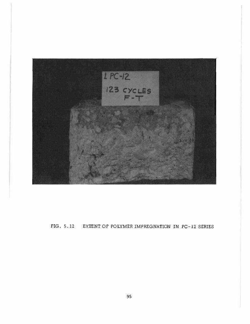
FIG. 5.12 EXTENT OF POLYMER IMPREGNATION IN PC-12 SERIES
95
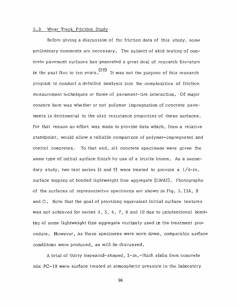
5.3 Wear Track Friction Study
Before giving a discussion of the friction data of this study, some
preliminary comments are necessary. The subject of skid testing of con-
crete pavement surfaces has generated a great deal of research literature
'h f' (28) I h f h' h In t e past Ive to ten years. t was not t e purpose 0 t IS researc
program to conduct a detailed analysis into the complexities of friction
measurement techniques or those of pavement-tire interaction. Of major
concern here was whether or not polymer impregnation of concrete pave-
ments is detrimental to the skid resistance properties of these surfaces.
For that reason an effort was made to provide data which, from a relative
standpoint, would allow a reliable comparison of polymer-impregnated and
control concretes. To that end, all concrete specimens were given the
same type of initial surface finish by use of a bristle broom. As a secon-
dary study, two test series (4 and 9) were treated to provide a 1/4-in.
surface topping of bonded lightweight fine aggregate (LWAT). Photographs
of the surfaces of representative specimens are shown in Fig. 5. 13A, B
and C. Note that the goal of providing equivalent initial surface textures
was not achieved for series 3, 5, 6, 7 I 8 and IO due to unintentional bond-
ing of some lightweight fine aggregate routinely used in the treatment pro-
cedure. However, as these specimens were worn down, comparable surface
conditions were produced I as will be discussed.
A total of thirty trapezoid- shaped I 2-in. -thick slabs from concrete
mix PC-I8 were surface treated at atmospheric pressure in the laboratory
96
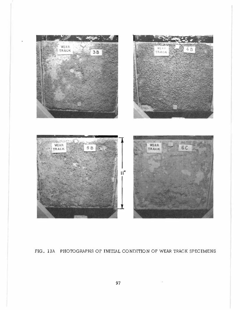
FIG. 13A PHOTOGRAPHS OF INITIAL CONDITION OF WEAR TRACK SPECIMENS
97
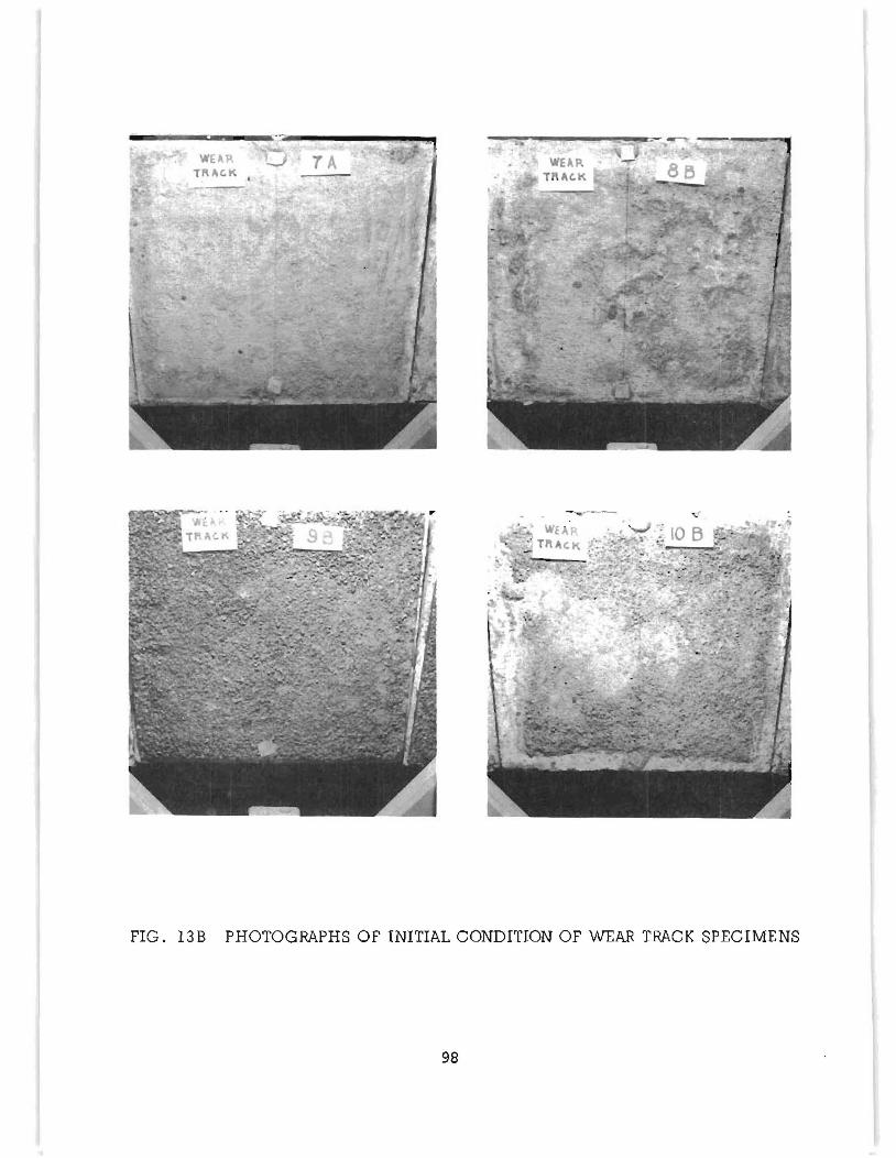
~---... - -....
FIG. 13B PHOTOGRAPHS OF INITIAL CONDITION OF WEAR TRACK SPECIMENS
98
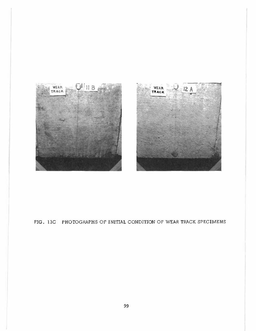
FIG. 13C PHOTOGRAPHS OF INITIAL CONDITION OF WEAR TRACK SPECIMENS
99
for evaluation of frictional and wear resistance properties. Three untreated
control specimens were also included in the test group. The impregnation
treatments selected for presentation here are given in Table 3.2. A de
scription of the test facility and procedures used to apply a simulated
vehicular loading to the treated surfaces is found in section A.2 of the
appendix. The vehicular loading consisted of 70 ,000 dry run revolutions
(140 ,000 wheel passes) of two non-grooved tires I otherwise meeting ASTM
E 274-70 , followed by 140 / 000 revolutions (280 / 000 wheel passes) under
wet conditions with no. 46 silicone carbide grit as a wearing agent.
Periodically I tire loading was stopped while measurements of surface
friction were made. Surface friction values for each specimen were deter
mined by use of the British Portable Testor (BPT) in accordance with ASTM
E 303-69. The results of the friction study are presented in Figs. 5.14
and 5.15 where the average friction numbers of selected specimen were
used to obtain friction curves through a total of 210 ,000 test revolutions.
For ease of comparison the average friction curve of the untreated control
specimens is shown in both figures.
The friction properties for the oven cured treatments are shown in
Fig. 5. 14. The initial skid numbers of all test series I including control
specimens I are relatively high with only two of five polymer treated series
falling slightly below the control values. As the dry wear loading progressed
to 70 ,000 revolutions I the control concrete surfaces were polished by the
tire wear I and the skid number decreased from 75 to 63. At the same time I
100
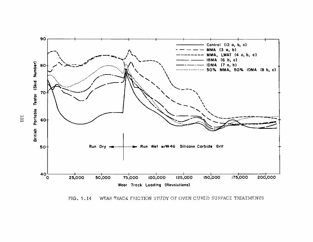
..... ~ ., .0 E ::J
Z
~ .:IC (f)
... 0 -.. ~ CI :is
t-' 0 0 -... t-' 0 a..
.c:: .. -... tD
90r--------r------~r_------~------~r_------~------~--------~------_4--~
80 ... , .............. " .
70
..... ...... /. ",-.
.... . .......... I --
~d/
60
50 Run Dry
Control (12 a, b, c)
- - - - - MMA (3 a, b) -------- MMA, LWAT (4.0, b, c)
ISMA (6 b, c)
----- IDMA (7 a, b) . ................... 50% MMA, 50% IDMA (8 b, c)
Run Wet w/#46 Silicone Carbide Grlt
40L-------~~------~---------+--------_+--------_+--------_+--------_+--------_+--~ 175,000 o 25,000 50,000 75,000 100,000 125,000 150,000 200,000
Wear Track LoadinQ (Revolutions)
FIG. 5.14 WEAR TRACK FRICTION STUDY OF OVEN CURED SURFACE TREATMENTS
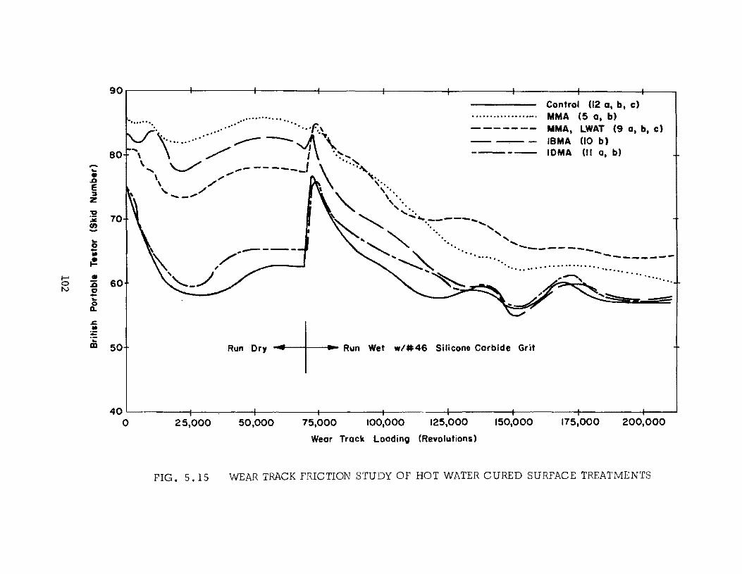
-.. • ..a E ::J Z
"0 ~ !! .. 0 -• {!!.
I-' • 0 :ii N CJ -..
~ .t::. • ; ';: ClI
90.-------~------~------_+------_;--------~------~------~------_+--~
.......... " .. Control (12 at b t c)
MMA (5 at b) ..... .... . .. ' .. ' ...... 'f.,
80" \ ........ ;.....- --1\\.,., ,..... '-../ -- -----.J ~ ... ~,
-- --"--MMA t LWAT (9 at bt c)
IBMA (10 b) IOMA (II at b)
70
60
50
\ "",,"'" ,. ,./ '\'.
'--."../ ." ,". " ". , '. ......
~' ....: .... -----.... " '. ....., ~" ,
... ,," " "" ~ ....... ....._--------... -. .......-.............. " ....... ,-.,.---_ ...... .......... '~- ............................ . .. " ... ...... . '.
Run Dry ..... --+--...... Run Wet w/#46 Silicone Carbide Grit
40~------+--_----~--------+-------~~-------+--------~--------4---------~--~ o 25,000 50,000 75,000 100,000 125,000 150,000 175,000 200,000
Wear Track Loading (Revolutions)
FIG. 5. 15 WEAR TRACK FRICTION STUDY OF HOT WATER CURED SURFACE TREATMENTS
all treated surfaces displayed approximately the same or slightly increased
skid numbers over their starting values. For the same loading period the hot
water cured specimens of Fig. 5.15 also maintained their relatively high
initial skid numbers except for series 11, which is seen to have polished in
a manner quite similar to that of the control specimen.
After the completion of the first 70, 000 test revolutions visual obser
vation of the specimen surfaces revealed that very little physical wear had
occurred. In fact, wear was so minor that, except for the rubber marking on
the specimen surfaces, the location of the wheel path was barely discern
ible. As a result, it is apparent that the differences in initial surface tex
ture as seen in Figs. 5. 13A, Band C were substantially maintained to this
point and thus resulted in the different skid properties as noted in Figs.
5 . 14 and 5. 15.
After 70, 000 test revolutions, the silicone carbide grit was applied
with water in order to wear more deeply into the specimen surfaces. As a
result, there was an immediate increase in the skid numbers of all speci
mens except those of series 3, which noticeably decreased. The greatest
increase in skid number occurred for the control series although it remained,
at best, approximately equal to the lower values of the treated specimens.
The influence of the grit in increasing the skid numbers of most of the
surfaces was short lived as polishing effects were noted in all specimens
after 5000 to 10, 000 additional test revolutions. At the same time, all
surfaces had begun to show visible signs of wear. From this point on, the
103
silicone carbide grit gradually wore down all the test surfaces so that defi
nite tire contact was made with the polymer-impregnated matrix of the
various series treatments. Evidence of this contact is seen in the surface
photographs of several specimens at the completion of testing as given in
Fig. 5.16.
As the grit wore into the specimens I a Significant polishing effect
was seen. The skid numbers of all specimens of Figs. 5.14 and 5.15
gradually decreased to relatively constant levels beyond about 150 ,000
revolutions. This would seem to indicate that the base skid number for
all specimens had been reached for these conditions of wear. At the same
time, any inconsistency in the initial surface condition of specimens had
been substantially negated by the action of the grit in wearing into all
surfaces. This then provided a fairly stable condition in which one can
compare the skid resistance properties of the impregnated and control
surfaces.
From Figs. 5.14 and 5.15 a comparison of the skid numbers for the
polished condition shows that the skid resistance of all polymer treated
surfaces equaled or exceeded that of the control specimens at test termina
tion. The differences in skid resistance of the treated specimens are seen
to be relatively insignificant as all except series 9 fall within a range of
58 to 61. The layer of bonded lightweight aggregate of series 9 provided a
final skid number of 64. Of most interest here, however, is that the polymer
impregnation of the concrete surfaces did not result in adverse skid
104
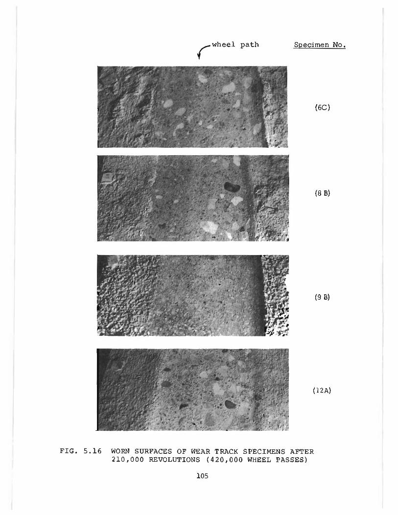
rWheel path Specimen No.
(6C)
(8 B)
(9 B)
(12A)
FIG. 5.16 WORN SURFACES OF WEAR TRACK SPECIMENS AFTER 210,000 REVOLUTIONS (420,000 WHEEL PASSES)
105
resistance properties as compared to control concretes. This conclusion is
based upon the procedures of test used here and. of course. may not be
completely relatable to field treatment methods. conditions of wear or skid
measurement techniques.
5.4 Wear Resistance
An evaluation of the wear resistance of many of the polymer-impregnated
and control concretes was made by two different techniques. The standard
sandblast abraslOn test (ASTM C 418- 57T) and a measurement of depth of
wear during wear track loading were used to provide data for two relatively
different mechanisms of wear. A description of the tes t equipment and pro
cedures used is found in sections A.2 and A.3 of the appendix.
5.4.1 Wear Track Abrasion--Periodically during wear track loading.
depth of wear measurements were made at O. 03-ft. increments across the
wheel path on each of the trapezoidal shaped specimens. These data were
then computer processed to provide a measure of the x-section area worn
away at various times during the loading history. The results of these
measurements through 210.000 wear track test revolutions were averaged
within each treatment series. and the resulting curves were plotted as shown
in Figs. 5.17 and 5.18.
From both Figs. 5.17 and 5.18 it can be seen that with the exception
of series 3 and 4. the wear characteristics of all specimens were similar
through the first 70 ,000 revolutions of test. At 70 ,000 test cycles the wear
area of series 3 and 4 was approXimately double that of all other specimens.
106
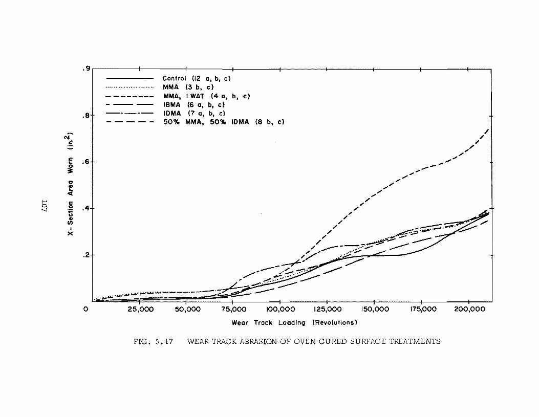
...... N . . 5
c ... 0 :. a • ... oct
I--' c 0 0 -....J :;::
U CI)
CI)
I )(
.9.---------+---------+---------~--------~--------_+--------~--------~~--------~--~
.8
.6
.4
.2
o
Control (12 a, b, c) MMA (3 b, c)
MMA, LWAT (4 a1 b 1 c) ISMA (6 0, b, c)
IDMA (7 a, b1 c) 50% MMA, 50% IDMA (8 b, c)
50,000 75,000 100,000 125,000
Wear Track LoadinQ (Revolutions)
150,000 175,000
FIG. 5.17 WEAR TRACK ABRASION OF OVEN CURED SURFACE TREATMENTS
200,000
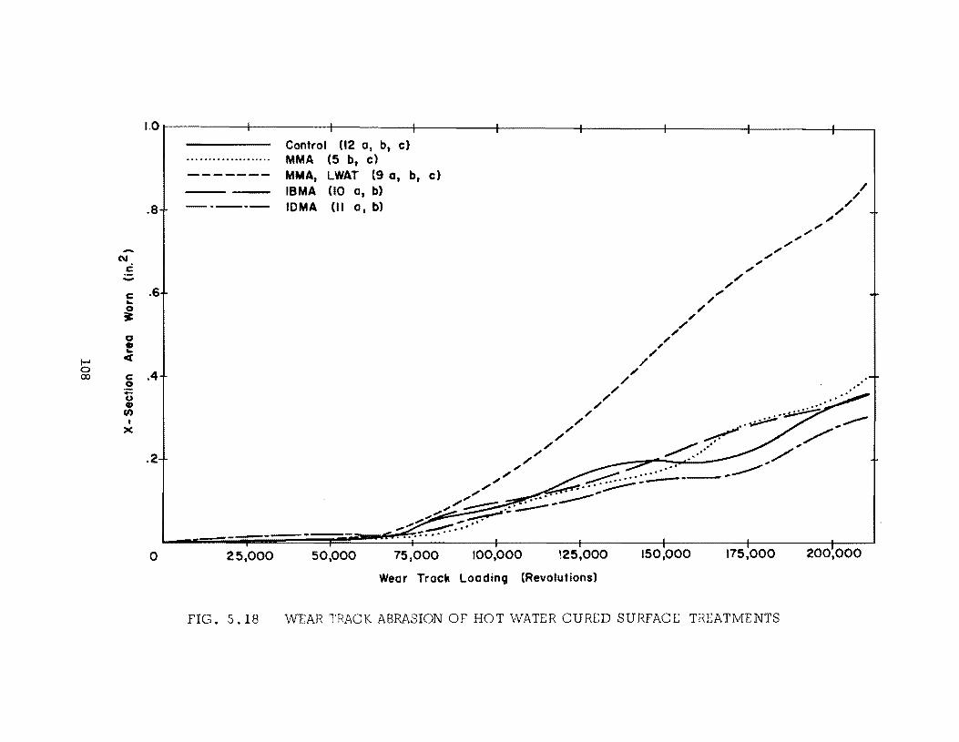
1.0
Control (12 a. b. c) ..... ...... ............... ..... MMA (5 b • c) ------- MMA. LWAT (9 a. b. e)
IBMA (10 a. b)
.8 -._--- IOMA 01 a. b)
N C
c .6 .. ~ 0 • ..
1-' « 0 .4 00 c
.2 -u ., (I)
I x
.2
... ~ .,~ ""........-
~ /'" ~.... ../' ...
------------------o 25.000 50,000 75.000 100,000 \25,000 150,000 175,000 200,000
Wear Track Loading (Revolutions)
FIG. 5.18 VlrEAR TRACK ABRASION OF HOT WATER CURED SURFACE TREATMENTS

Specimen 9A
(LWAT)
Specimen lOB
FIG. 5.19 X-SECTION WEAR RESULTING FROM WEAR TRACK LOADING
109
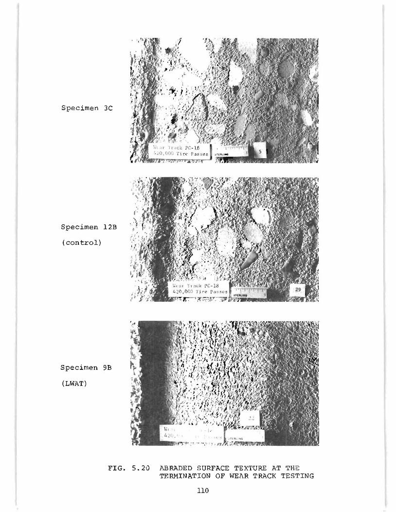
Specimen 3C
Specimen l2B
(control)
Specimen 9B
(LWAT)
FIG. 5.20 ABRADED SURFACE TEXTURE AT THE TERMINATION OF WEAR TRACK TESTING
110
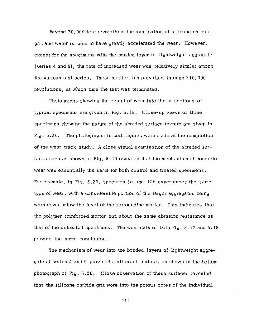
Beyond 70,000 test revolutions the application of silicone carbide
grit and water is seen to have greatly accelerated the wear. However,
except for the specimens with the bonded layer of lightweight aggregate
(series 4 and 9), the rate of increased wear was relatively similar among
the various test series. These similarities prevailed through 210,000
revolutions I at which time the test was terminated.
Photographs showing the extent of wear into the x- sections of
typical specimens are given in Fig. 5.19. Close-up views of three
specimens showing the nature of the abraded surface texture are given in
Fig. 5.20. The photographs in both figures were made at the completion
of the wear track study. A close visual examination of the abraded sur
faces such as shown in Fig. 5.20 revealed that the mechanism of concrete
wear was essentially the same for both control and treated specimens.
For example, in Fig. 5.20, specimen 3c and l2b experiences the same
type of wear, with a considerable portion of the larger aggregates being
worn down below the level of the surrounding mortar. This indicates that
the polymer reinforced mortar had about the same abrasion resistance as
that of the untreated specimens. The wear data of both Fig. 5.17 and 5.18
provide the same conclusion.
The mechanism of wear into the bonded layers of lightweight aggre
gate of series 4 and 9 provided a different texture I as shown in the bottom
photograph of Fig. 5.20. Close observation of these surfaces revealed
that the silicone carbide grit wore into the porous cores of the individual
111
lightweight aggregate particles. The outer skins of these particles and
the cementing matrix of the polymer were more abrasive resistant and formed
raised outlines on the worn surfaces. This texture was probably responsi
ble for the relatively high skid resistance of these specimens, as reported
in the previous section. However, from a wear standpoint these surfaces
were less durable than those of all other series, with approximately 100 per
cent greater area worn.
From an overall evaluation of the wear depth data, it is concluded
that the wear resistance of the polymer impregnated concretes was similar
to that of the control concrete. However, there is some indication that in
the absence of unintentionally bonded lightweight aggregate I the treated
surfaces may be slightly more abrasive resistant than the control concrete.
5.4.2 Sandblast Abrasion Resistance--A11 concretes subjected to
the water penetration test were also evaluated by sandblast abrasion tests.
Two or three specimens were cut from the surfaces of the broken halves
after water penetration testing. The standard ASTM C 418- 67T procedure
was followed except for a required modification in the method of determin
ing abraded volume. A complete discussion of the procedure used is found
in section A.3 of the appendix.
The results of the sandblast abrasion study are given in Fig. 5.21
where control specimens are shown as solid bars for easy comparison wi th
companion treatments. A detailed summary of the treatment method used
for these specimens is given in Tables 3.1 and 3.3. The mix properties of
112
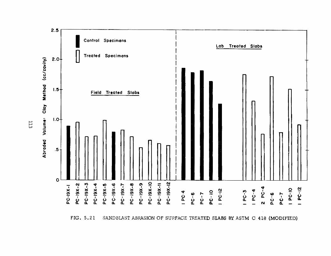
2.5 I
I Control Specimens Lob Treated Slobs
- 2.0 ,.. - 0 Treated Specimens r-
'; CJ U ...... U r-U ~ --0 0 1.5 .I::. - ~ -Field Treated Slobs • :'IE
~ ,.. .2 (.)
.. 1.0 I-' • I-' e w .2
r-I'"
~ ~
~
~ ~
"0 ~ • "0 CJ .5 ... .0 c:r:
o I '---- I...-..
N f() q- It) CD ..... CD <n 0 N I I I I I I I I I I I I q-
Q N X X X X X X X X X X X X q- 0 N f() q- I
2:! 2! 2! <n en <n <n <n en <n 2! <n CD ..... I I I (.) CD ..... , I
I I I I I I I I I l I t 0 I I I (.) (.) (.) Q. I , (.) (.) (.)
~ (.) (.) (.) (.) (.) (.) (.) (.) (.) (.) Q. (.) 0 (.) Q. Q. Q. 0 (.) Q. Q.
Q. Q. Q. Q. Q. Q. Q. Q. Q. Q. Q. Q. Q. Q. N Q. Q.
FIG. 5.21 SANDBLAST ABRASION OF SURFACE TREATED SLABS BY ASTM C 418 (MODIFIED)
the control concretes are found in Table A-I of the appendix.
For the field treated specimens of Fig. 5.21, the control concretes
gave an average abrasion loss of 0.85 cc per test cavity. Only the treat
ments of PC 19X-2 and 5 slightly exceeded the control values, with abra
sion volumes of 0.96 and 0.99 respectively. The most abrasive resistant
treatments of the field treated specimens were those of series 9, 10 I 11
and 12. Within this group the abraded volumes were 64 to 78 percent of
that of the control concrete. From a comparison of all field treatment
specimens, it appears that impregnation did slightly improve sandblast
abrasion resistance of most of the test series. Of those showing the most
improvement, series 11 and 12 were also found to be stable by freeze-thaw
evaluation.
In the analysis of the laboratory treated test series, one first notes
the much larger abrasion losses of the control concrete and severa1impreg
nated specimens. These increased abrasion volumes are primarily due to
the lower compressive strength of the laboratory treated concretes (see
Table A-I). Since'the same types of aggregates were used in all mixes,
the relationship between strength and abrasion resistance indicated in
Fig. 5.21 is to be expected.
Among the polymer treatments of the laboratory series, two show a
significant improvement in abrasion loss over that of control specimens.
The treatments of series 2PC-4 and PC-7 provided abrasion losses respec
tively amounting to 43 and 45 percent of that of the average control concrete
114
* (lPC- 4, PC- 6, PC-7 and PC-IO). It should be noted here tha t treated
series PC-7 incorporated a bonded layer of lightweight fine aggregate which
was subjected to sandblast testing. In addition, the abrasion loss of
series IPC-12 was 70 percent of its companion control concrete while that
of treatment IPC- 4 was 74 percent of the average control value. Thus,
it can be concluded that for concrete of the quality used here, selected
polymer treatments do provide increased abrasion resistance to the sand-
blast method.
A general comparison of the results of the wear track and sandblast
abrasion studies is helpful at this pOint. First, since there are no direct
test comparisons, a rating of the two test methods is difficult. The re-
suits of both tests on bonded lightweight fine aggregate seem to be contra-
dictory with poor resistance to wear track abrasion and high resistance to
sandblast abrasion. This comparison serves to clearly illustrate that the
mechanisms of abrasion are very different in the two methods. As a result,
future efforts will be made to determine what relationship I if any I exists
between the two methods of wear evaluation. This is appropriate since
each method has meaningful advantages. For example, the sandblast test
has been standardized for concrete studies. On the other hand I abrasion
loss during wear track loading is at least visibly related to traffic abrasion
of pavement surfaces.
*These concretes were of identical mix design I and strengths were similar, ranging from 4160 to 4500 psi.
115
5.5 Effects of Static and Cyclic Loading:
To investigate the behavior of polymer-impregnated concrete under
flexural loadings, a series of cyclic loadings on reinforced concrete beams
with surface treatments is in progress. Each beam is 4 in. wide, 5-1/2 in.
deep and 60 in. long, reinforced with a no. 5 grade 40 reinforcing bar
with 1-1/2 in. clear cover. Control and treated beams are being tested
under static and cyclic loadings. Equal concentrated loads are applied at
a distance of 0.4 times the span length from each end. A span length of
56 in. is being used. The tests are still in progress.
The specimens were cast in the field at the same time slabs for field
treatments were cast. The windy conditions caused the concrete to dry
rapidly, and as a result the specimens were slightly honeycombed in spite
of prolonged efforts to vibrate the concrete. Only the best specimens were
selected for use in this study.
Table 5.1 summarizes the tests completed to date. The surface
treated specimens were treated the same as the laboratory test slabs de
scribed in Chapter 3. Curing was with hot water. The depth of surface
treatment in the three treated slabs tested under static load ranged from
1/2 in. to 3/4 in. The concrete was probably more impermeable at the
surface due to the longer period of vibration during casting.
The control specimens developed considerable flexural cracking on
the tension side prior to failures. The failure was typical for under
reinforced beams I With a final compression failure occurring after con sid-
116
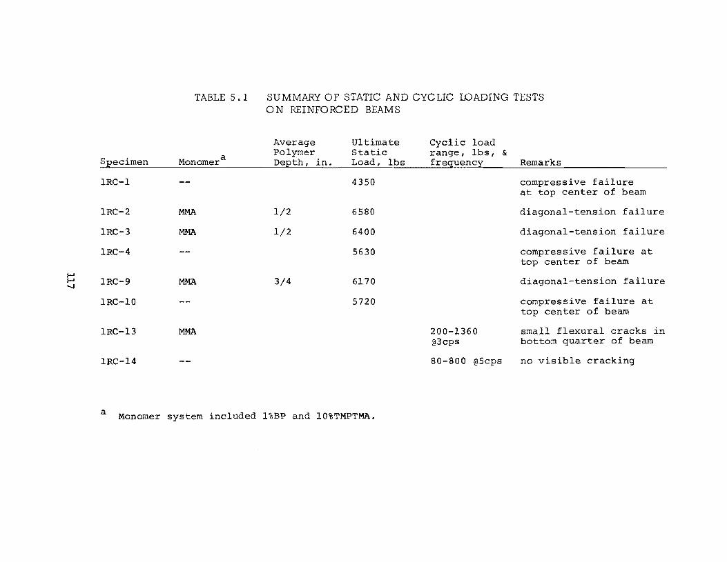
I-' I-' -.....J
TABLE 5.1
SEecimen Monomer a
lRC-l
lRC-2 MMA
lRC-3 MMA
lRC-4
lRC-9 MMA
lRC-lO
lRC-13 MMA
lRC-14
SUMMARY OF STATIC AND CYCLIC WADING TESTS ON REINFO RCED BEAMS
Average Ultimate Cyclic load Polymer Static range, lbs, & DeEth, in. Load, lbs freguency Remarks
4350 compressive failure at top center of beam
1/2 6580 diagonal-tension failure
1/2 6400 diagonal-tension failure
5630 compressive failure at top center of beam
3/4 6170 diagonal-tension failure
5720 compressive failure at top center of beam
200-1360 small flexural cracks in @3cps bottom quarter of beam
80-800 @5cps no visible cracking
a Monomer system included l%BP and 10%TMPTMA.
erable yielding of the steel had occurred. The average failure load was
52301bs.
The surface treated beams gave little evidence of cracking before a
sudden diagonal tension failure occurred at an average load of 6380 lbs.
Apparently, the higher strength and stiffness of the relatively shallow zone
of polymer-impregnated concrete was large enough to result in the neutral
axis lying significantly nearer the compression face. The accompanying
increase in the lever arm between the resultant compressive and tensile
forces was large enough to prevent significant yielding of the reinforcing
from occurring before the failure occurred in shear. Further tests will be
performed on beams with shear reinforcing.
Cyclic tests have just begun. Initially a control beam underwent
2, 000, 000 cycles of load which varied from 80 to 800 lbs. at 3 cps. No
visible signs of distress were observed.
A surface-treated beam has undergone 2, 000 ,000 cycles of load
ranging from 200 to 1360 lbs. at 3 cps. A calculated stress in the rein
forcing of 20,000 psi occurs at a load of 1360 lbs. Some small flexural
cracks were observed during the test in the bottom quarter of the beams;
however I there was no evidence of spalling or separation of the pol ymer
impregnated concrete from the rest of the beam. The beams tested under
cyclic loads will be statically tested to determine if the fatigue conditions
have any effect on the ultimate strength of the beams.
118
CHAPTER 6.
Other Applications
6.1 Polymer-Impregnated Piles
The use of fully-impregnated piles in an ocean environment has been
considered to be a potential application of polymer-impregnated materials.
Both wood and concrete are subject to attack in a marine environment.
In many coastal areas, wood is attacked by marine borers which
rapidly bore through the wood until it is destroyed. There are some pre
servatives which offer protection against attack by some species I but
apparently no single treatment offers protection against all species. There
has been speculation that polymer-impregnated wood would be resistant to
attack.
Concrete piles are subject to corrosion of the reinforcement which is
accelerated by the presence of salt. Polymer-impregnated concrete is
essentially impermeable I which reduces the probability of sale water reach
ing the reinforcing steel.
Concrete and wood pile specimens (3 x 3 x 46 in.) were impregnated
with both MMA and styrene systems. The treatment summary is given in
Table 6.1. The concrete mix design is given in the appendix. Each
119
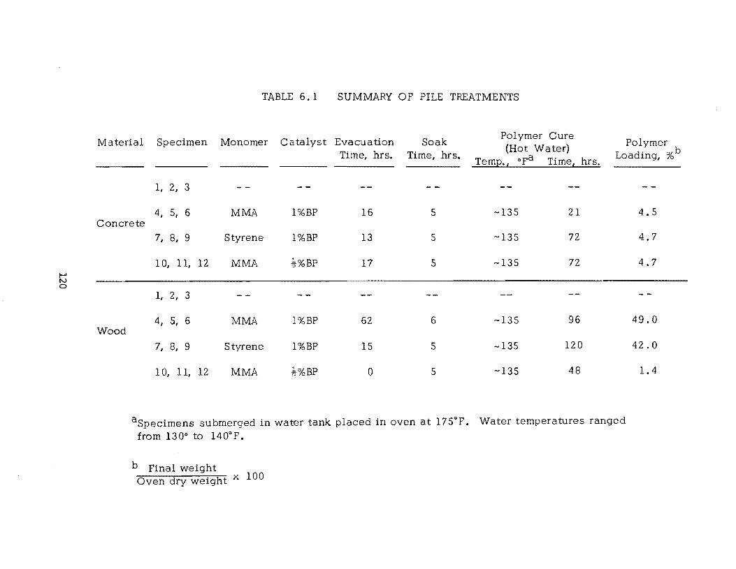
I-' N 0
TABLE 6.1 SUMMARY OP PILE TREATMENTS
Material Monomer Evacuation Soak Polymer Cure
Specimen Catalyst Polymer Time, hrs. Time, hrs.
(Hot Water) Loading, %b
Temp., opa Time, hrs.
I, 2, 3
4, 5, 6 MMA l%BP 16 5 -135 21 Concrete
Wood
7, 8, 9 Styrene l%BP 13 5 -135 72
10, II, 12 MMA *%BP 17 5 -135 72
I, 2, 3
4, 5, 6 MMA l%BP 62 6 -135 96
7, 8, 9 Styrene l%BP 15 5 -135 120
10, II, 12 MMA BP 0 5 -135 48
aSpecimens submerged in water tank placed in oven at 175°P. Water temperatures ranged from 130° to l400p.
b Pinal weight Oven dry weight x 100
4.5
4.7
4.7
49.0
42.0
1.4
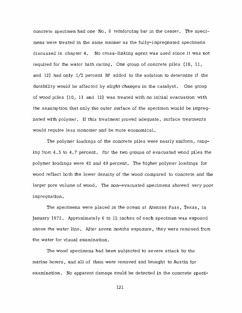
concrete specimen had one No. 6 reinforcing bar in the center. The speci
mens were treated in the same manner as the fully-impregnated specimens
discussed in chapter 4. No cross-linking agent was used since it was not
required for the water bath curing. One group of concrete pile s (IO, 11,
and 12) had only 1/2 percent BP added to the solution to determine if the
durability would be affected by slight changes in the catalyst. One group
of wood piles (10, 11 and 12) was treated with no initial evacuation with
the assumption that only the outer surface of the specimen would be impreg
nated with polymer. If this treatment proved adequate, surface treatments
would require less monomer and be more economical.
The polymer loadings of the concrete piles were nearly uniform, rang
ing from 4.5 to 4.7 percent. For the two groups of evacua ted wood piles the
polymer loadings were 42 and 49 percent. The higher polymer loadings for
wood reflect both the lower density of the wood compared to concrete and the
larger pore volume of wood. The non-evacuated specimens showed very poor
impregna tion.
The specimens were placed in the ocean at Aransas s, Texas, in
January 1972. Approximately 6 to 12 inches of each specimen was exposed
above the water line. After seven months exposure, they were removed from
the water for visual examination.
The wood specimens had been subjected to severe attack by the
marine borers, and all of them were removed and brought to Austin for
examination. No apparent damage could be detected in the concrete speci-
121
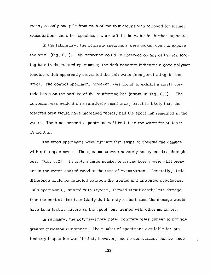
mens I so only one pile from each of the four groups was removed for further
examination; the other specimens were left in the water for further exposure.
In the laboratory, the concrete specimens were broken open to expose
the steel (Fig. 6.1). No corrosion could be observed on any of the reinforc
ing bars in the treated specimens; the dark concrete indicates a good polymer
loading which apparently prevented the salt water from penetrating to the
steel. The control specimen, however I was found to exhibit a small cor
roded area on the surface of the reinforcing bar (arrow in Fig. 6.1). The
corrosion was evident on a relatively small area, but it is likely that the
affected area would have increased rapidly had the specimen remained in the
water. The other concrete specimens will be left in the water for at least
18 months.
The wood specimens were cut into thin strips to observe the damage
within the specimens. The specimens were severely honey-combed through
out. (Fig. 6.2). In fact, a large number of marine borers were still pres
ent in the water-soaked wood at the time of examination. Generally, little
difference could be detected between the treated and untreated specimens.
Only specimen 8, treated with styrene I showed significantly less damage
than the control, but it is likely that in only a short time the damage would
have been just as severe as the specimens treated with other monomers.
In summary, the polymer-impregnated concrete piles appear to provide
greater corrosion resistance. The number of specimens available for pre
liminary inspection was limited, however, and no conclusions can be made
122
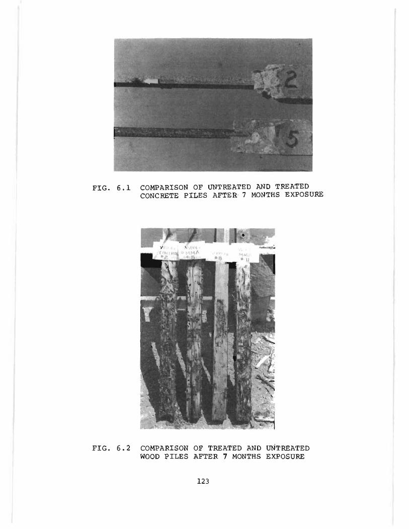
FIG. 6.1 COMPARISON OF UNTREATED AND TREATED CONCRETE PILES AFTER· 7 MONTHS EXPOSURE
FIG. 6.2 COMPARISON OF TREATED AND uNTREATED WOOD PILES AFTER 7 MONTHS EXPOSURE
123

until the remainder of the specimens are observed. The polymer-impregnated
wood specimens indicated no appreciable increase in resistance to marine
borers. A further investigation to identify monomer systems I or additives to
monomer systems I to provide effective resistance to the borers has thus far
been unsucces sful.
6.2 Crack- Repaired Beams
One possible application of polymer-impregnation techniques is the
repair of cracked bridge slabs. The penetration and bonding characteristics
of the monomer systems give promise that cracks can be sealed and that
some structural integrity can be restored to the concrete.
The evaluation of crack-repair techniques utilized 3 x 3 x 14 in.
beams. The impregnated control specimens were subjected to the modulus
of rupture test to determine the strength and to provide speCimens to be
"repaired." The two halves of each beam were placed together with a
closed crack at the bottom (the original compression face) and a crack at
the top ranging in width from 0.1 mm to 1 mm. Silicone adhesive was
used to seal the crack on the bottom and sides and to form a shallow
(:;;;: 1/4 in.) dike around the crack on the top surface. The finite width of
the crack permi tted the monomer I ponded on the surface I to rapidly pene
trade through the depth of the beam. After curing at room temperature or in
a 125° F oven I the beam was again subjected to the modulus of rupture test
with the beam placed with the same face in compression as in the initial
test.
124
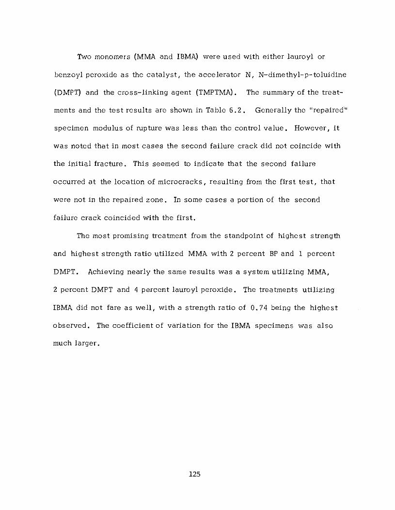
Two monomers (MMA and IBMA) were used with either lauroyl or
benzoyl peroxide as the catalyst, the accelerator N, N-dimethyl-p-toluidine
(DMPT) and the cross-linking agent (TMPTMA). The summary of the treat
ments and the test results are shown in Table 6.2. Generally the "repaired"
specimen modulus of rupture was less than the control value. However, it
was noted that in most cases the second failure crack did not coincide with
the initial fracture. This seemed to indicate that the second failure
occurred at the location of microcracks, resulting from the first test, that
were not in the repaired zone. In some cases a portion of the second
failure crack coincided with the first.
The most promising treatment from the standpoint of highest strength
and highest strength ratio utilized MMA with 2 percent BP and 1 percent
DMPT. Achieving nearly the same results was a system utilizing MMA,
2 percent DMPT and 4 percent lauroyl peroxide. The treatments utilizing
IBMA did not fare as we 11, with a strength ra tio of O. 74 being the highe s t
observed. The coefficient of variation for the IBMA specimens was also
much larger.
125
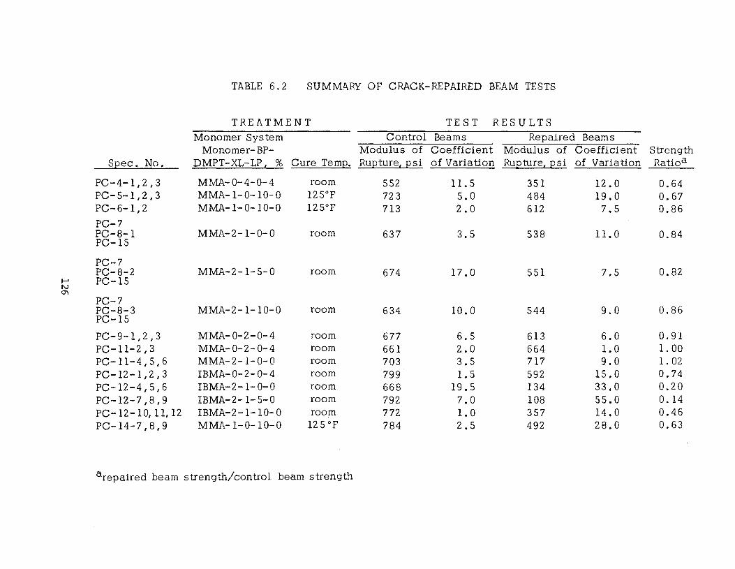
TABLE 6.2 SUMM.ll..RY OF CRACK-REPAIRED BEAM TESTS
TREATMENT TE S T RESULTS Monomer System Control Beams Repaired Beams
Monomer- BP- Modulus of Coefficient Modulus of Coefficient Strength S2ec. No. DMPT-XL-LP t % Cure Tem2. RU2ture, 2 si of Variation RU2ture, 2 si of Variation Ratioa
PC-4-1,2,3 MMA-0-4-0-4 room 552 11.5 351 12.0 0.64 PC-5-1,2,3 MMA-1-0-10-0 12soF 723 5.0 484 19.0 0.67 PC-6-1,2 MMA-1- 0-10-0 12soF 713 2.0 612 7.5 0.86 PC-7 PC-8-1 MMA-2-1- 0- 0 room 637 3.5 538 11.0 0.84 PC-IS
PC-7 PC-8-2 MMA-2-1-5-0 room 674 17.0 551 7.5 0.82
...... PC-IS tv
'" PC-7 PC-8-3 MMA-2-1-10-0 room 634 10.0 544 9.0 0.86 PC-IS
PC-9-1,2,3 MMA-0-2-0-4 room 677 6.5 613 6.0 0.91 PC-ll-2,3 MMA-0-2-0-4 room 661 2.0 664 1.0 1. 00 PC- 11- 4 , 5 , 6 MMA-2-1-0-0 room 703 3.5 717 9.0 1. 02 PC-12 -1 ,2 , 3 IBMA-0-2-0-4 room 799 1.5 592 15.0 0.74 PC-12-4,5,6 IBMA-2-1-0-0 room 668 19.5 134 33.0 0.20 PC -12 - 7 , 8 , 9 IBMA-2-1-5-0 room 792 7.0 108 55.0 0.14 PC-12-10, 11, 12 IBMA-2-1-10-0 room 772 1.0 357 14.0 0.46 PC-14-7,8,9 MMA-I-0-10-0 12 S OF 784 2.5 492 28.0 0.63
arepaired beam strength/control beam strength
CHAPTER 7.
Implementation
7 • 1 Field Application
The investigation of polymer-impregnated concrete surface treatments
has given the goal of developing practical and economical techniques the
top priority. As a result, the procedures that have been developed appear to
be suitable for highway application. It should be emphasized that the appli
cation techniques have been regularly improved since the beginning of the
study, and the probability is quite good that further improvements will be
made in the future. The following discussion summarizes recommendations
for applying surface treatments based on the present state-of-the-art.
7.1.1 Drying the Slab--The slab should have an age of at least two
months or more be£~re application of the monomer I to permit as much air
drying of the slab as possible. The slab should be protected from rain and
dew by a plastic cover prior to monomer application. The clear plastic
should be supported several inches above the slab surface to serve as a
solar heater to assist the drying. However I there should be provision for
air circulation to prevent moisture condensation. (If additional drying is
necessary I warm air heaters in shallow enclosures over the slabs appear to
127
be the most feasible solution.) Studies are currently undeIWay to identify
a method for determining when the slab is sufficiently dry to obtain an ade
quate surface treatment.
7.1.2 Application of Monomer--The slab should be covered with
approximately 1/4 in. dry natural sand to prevent evaporation. For large
scale treatments of bridge decks I the monomer would pe applied with a
spray gun that would utilize a mixing nozzle to eliminate the hazard of pre
mixing and storing large quantities of the monomer system. The estimated
application rate would be in the range of 50 to 100 sq ft per minute which
would permit the equivalent of 250 to 500 ft of a single lane to be wetted
per hour. The wetted slab should be immediately covered with plastic film
to prevent evaporation. A soak time of 10 hours is preferable to permit ade
quate penetration into the concrete. In cool weather I the soaking period
could be during the day. When the slab temperature exceeds 1000 P during
the day I the slab should be covered to prevent premature polymerization of
the monomer I or the soak period could be overnight to minimize the tempera
ture and evaporation effects. One intermediate application of monomer after
4 to 6 hours may be necessary if the sand becomes dry.
7.1.3 Curing:--Aiter the soak time I curing could be accomplished by
one of several methods:
1. Hot Water--Adjustable wood or metal frames with plastiC
sheets draped inside to hold the water would be applied over the slabs. For
relatively flat decks the frames could be approximately 12 x 20ft; for slabs
128
with steep slopes the frames would be further divided through the center to
"terrace" the slab to prevent the necessity of excessive ponding of the
water on one side to cover the entire area. Water heated by portable units
would be pumped into the shallow ponds and could perhaps be recirculated
through the heaters to maintain a water temperature of 1600 p to 200o P. A
minimum depth of 2 to 3 in. of water would be preferable. This would re
quire about 1. 5 to 2.5 gal/sq ft. Each 2 a ft of a single lane width of
bridge deck would require about 400 to 500 gals of water.
As an alternative to the use of water ponded in the open vats I the
possibility of using a closed system is being investigated. This system
would involve a large bag similar to a hot water bottle that could cover an
area of perhaps 12 x 20 ft. The bag could be relatively thin since it would
be connected to a water heater and circulating pump. The closed system
would be easier to move / would have less heat loss / would minimize
evaporation/ and would probably require less water.
The water would be left on the slab for one or more hours / depending
upon the temperature / after which the apparatus could be moved onto the
next section to be cured.
2. Steam Heat--This method / which is in the proces s of be
ing evaluated I perhaps offers more potential than hot water. This proposed
method would require an enclosure to be placed over the soaked slab.
Steam from portable generators would be used to heat the interior of the
enclosure. The enclosures could consist of light metal frames approximately
129
6 x 12 ft supported by short (= 1 ft) legs. The frames would be placed
side by side to provide as large an enclosure as required. Canvas could
be used to cover the top and sides; there would be no need to make the
enclosure air tight. The steam would be regulated to maintain an air
temperature inside the enclosure of 125 to 175°F for the required cure time I
which should not exceed 1 to 2 hours.
The tentative advantages of this method over the hot water are:
(1) much less water required; (2) minimizes the problem of sloping decks;
(3) simpler apparatus; (4) the potential of curing larger areas at one time;
and (5) the ability to achieve higher temperatures.
3. Warm Air Heat--Warm air heat could be the most feasible
solution for curing in some areas I especially if warm air drying is necessary
prior to application of monomer. Enclosures similar to those proposed for
steam curing would probably be adequate. The advantages of this method
are: (1) ability to cure sloping decks and large areas; (2) no water required~
(3) equipment is simple and readily available; and (4) the same apparatus
can be used for preliminary slab drying.
7.2 Cost of Treatments
The cost of the treatments applied to actual bridges in the field can
only be estimated at this time since no experience has been obtained with
the application and curing methods on a large scale. The cost will involve
many variables: (1) amount of initial drying required for the slab; (2) types
of monomer systems; (3) evaporation losses; (4) type of curing system;
130
(5) availability of required apparatus; and (6) labor rates.
A range of estimated costs is as follows:
Drying slab
Monomer system I applications and evaporation barriers
Curing
Total estimated cost
$ 0 . 05 to O. 15/ s q
$0.30 to 0.45/sq
$ O. 1 0 to O. 30/ s q
$ 0 . 45 to O. 90/ s q
ft
ft
ft
ft
These estimates assume that the apparatus costs would be amortized
large- scale us age.
by
The cost of polymer-impregnated surface treatments I for the bene-
fits desired, seems economically feasible in comparison to the high cost
of maintenance I repair and replacement using alternate methods. It is
difficult to place a value on the benefits derived from not having to close
a bridge for repair or maintenance for a much longer period of time.
131

!!!!!!!!!!!!!!!!!!!"#$%!&'()!*)&+',)%!'-!$-.)-.$/-'++0!1+'-2!&'()!$-!.#)!/*$($-'+3!
44!5"6!7$1*'*0!8$($.$9'.$/-!")':!
CHAPTER 8.
Conclusions
The investigation reported herein has had the objective of developing
uses of polymer-impregnated concrete for highway applications. Primarily
the emphasis has been on development of surface treatments for bridge
decks I but other applications such as piles and repair of cracked slabs have
been studied. The following conclusions summarize the inve stigation.
Monomer Systems:
The most effective monomers identified for surface treatments are I
in order: methyl methacrylate I isobutyl methacrylate I and isodecyl
methacrylate. With the addition of 1 percent (wt) catalyst (benzoyl
peroxide) and 10 percent (wt) cross-linking agent (trimethylolpropane
trimethacrylate) the monomer solution will polymerize within con
crete at 125°F.
Application Techniques:
Best results for surface treatments are obtained by soaking the
concrete I covered with 1/4 in. of sand I with monomer solution for a
minimum of 10 hours. During the soak period the concrete tempera
ture should not exceed 90° to 95°F to prevent premature polymeriza
tion.
133
Curing Methods:
The most promising methods for applying the necessary heat to
polymerize the monomer systems are: (1):::: 3 in. of ponded hot water
(::.- 190°F to 200°F); (2) steam heating inside a curtain enclosure; and
(3) warm air inside an enclosure I provided by heaters or a forced air
system.
Stength and Stiffness Increases:
The increase in compressive strength for fully-impregnated con
crete ranged up to 3.28 times the untreated specimen strengths.
Modulus of rupture values up to 2.39 times those for control speci
mens were obtained I while tension strengths 2.06 times higher were
obtained. The modulus of elasticity for treated concrete ranged up
to 6.35 x 10⁶ psi I which was slightly less than twice the value for
control specimens.
Freeze-thaw Study:
Freeze-thaw durability was effectively measured in terms of
strain at the tops of slabs during test. The parameter was considered
a measure of volume stability.
High quality I air entrained control concretes compared favorably
in volume stability with laboratory impregnated slabs.
Laboratory impregnated slabs were generally more resistant to
scaling than air-entrained control slabs.
Non-air-entrained control slabs rapidly deteriorated as indicated
134
by volume instability while all surface treated slabs were relatively
more durable. Four of the field treatments apparently provided com
plete freeze-thaw protection throughout the test.
Failure of freeze-thaw specimens was normally observed when
ever top strains exceeded +SOOfJ. in./in.
Water Tightness Study:
Polymer impregnation resulted in improved water tightness in all
tests. In many cases impregnation entirely prevented water penetra
tion as measured by the test used.
Several concretes found to be water-tight initially failed in
freeze-thaw tests. In most cases the water penetration resistance of
these specimens was decreased by the thaw exposure.
Several freeze-thaw specimens which failed by loss of volume
stability were found to have remained essentially water-tight during
freeze-thaw exposure. For these specimens I strain incompatibility
is suspected as a possible failure mechanism.
Wear Track Friction Study:
For the first 140 ,000 wheel passes under dry conditions I all but
one polymer-impregnated surface had significantly higher skid resist
ance than that of control concrete. The control and one treated series
each experienced a decreasing skid number as they were polished by
the simulated vehicular loading.
Beyond 140 ,000 wheel passes all specimens were significantly
135
worn by the use of silicone carbide grit and water applied during wear
loading. At the termination of tests, all treated specimens had
reached a stable skid number which equalled or slightly exceeded that
of the control specimen.
Wear Track Abrasion Study:
Surface wear induced by simulated traffic loading was found to be
approximately equal for treated and control specimens with the excep
tion of those with 1/4 in. thick bonded lightweight fine aggregate
which experienced significantly more wear.
Sandblast Abrasion Study:
Eight of ten field-treated slabs were slightly more abrasion re
sistant than companion control specimens. The most effective treat
ment resulted in an abraded volume of 64 percent of that of the control
concrete.
When a lower quality concrete was used for laboratory treatment
studies I significant improvements in abrasion resistance were pro
vided by impregnation. The most effective treatment resulted in an
abraded volume of 43 percent of that of companion control concrete.
Static and Cyclic Tests of Surface-Treated Reinforced Beams:
The static strength of surface-treated reinforced beams was found
to be 22 percent greater with a diagonal tension failure resulting, than
that of untreated beams I which failed in flexure. No spaUing has
occurred in the cyclic tests of surface treated beams.
136
Repair of Cracked Slabs:
Small unreinforced concrete beams I broken in flexure I were re
paired using several methyl methacrylate systems cured at room
temperature. The original moduli of rupture were obtained.
Po lymer- Impregnated Concrete and Wood Piles:
Fully-impregnated wood piles placed in sea water on the Texas
coast were severely attacked by marine borers after seven months
exposure. Fully-impregnated reinforced concrete piles showed no
evidence of corrosion after the same exposure while the control
specimen did show signs of corrosion.
Implemen ta tion Feasibil1 ty:
The polymer-impregnated surface treatments can be obtained for
an estimated cost of $0.45 to $0.90 which is competitive with cur
rent methods of repair and maintenance I especially when the improve
ments in properties are considered. The methods of application and
curing appear to be feasible and practical.
137

!!!!!!!!!!!!!!!!!!!"#$%!&'()!*)&+',)%!'-!$-.)-.$/-'++0!1+'-2!&'()!$-!.#)!/*$($-'+3!
44!5"6!7$1*'*0!8$($.$9'.$/-!")':!

APPENDIX

!!!!!!!!!!!!!!!!!!!"#$%!&'()!*)&+',)%!'-!$-.)-.$/-'++0!1+'-2!&'()!$-!.#)!/*$($-'+3!
44!5"6!7$1*'*0!8$($.$9'.$/-!")':!
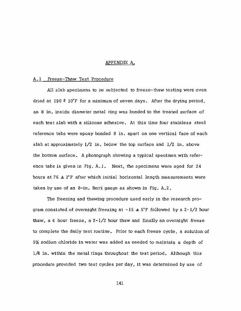
APPENDIX A.
A.I Preeze-Thaw Test Procedure
All slab specimens to be subjected to freeze-thaw testing were oven
dried at 190 ± lOOp for a minimum of seven days. After the drying period I
an a in. inside diameter metal ring was bonded to the treated surface of
each test slab with a silicone adhesive. At this time four stainless steel
reference tabs were epoxy bonded a in. apart on one vertical face of each
slab at approximately 1/2 in. below the top surface and 1/2 in. above
the bottom surface. A photograph showing a typical specimen wi th refer
ence tabs is given in Pig. A. 1. Next, the specimens were aged for 24
hours at 76 ± 3°P after which initial horizontal length measurements were
taken by use of an a-in. Berri gauge as shown in Pig. A.2.
The freezing and thawing procedure used early in the research pro
gram consisted of overnight freezing at -15 ± Sop followed by a 2-1/2 hour
thaw I a 4 hour freeze I a 2-1/2 hour thaw and finally an overnight freeze
to complete the daily test routine. Prior to each freeze cycle, a solution of
5% sodium chloride in water was added as needed to maintain a depth of
1/4 in. within the metal rings throughout the test period. Although this
procedure provided two test cycles per day, it was determined by use of
141
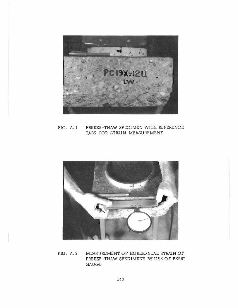
FIG. A.I FREEZE-THAW SPECIMEN WITH REFERENCE TABS FOR STRAIN MEASUREMENT
FIG. A.2 MEASUREMENT OF HORIZONTAL STRAIN OF FREEZE-THAW SPECIMENS BY USE OF BERRI GAUGE
142
thermocouple readings that those specimens which absorbed large amounts
of the ponded water were not adequately frozen or thawed during the day
test cycle. The test procedure was therefore modified to provide overnight
freezing followed by an 8 hour thaw during the day. Also I the use of salt
water was discontinued and tap water was used as the freezing solution in
all subsequent tests. One other modification of the test procedure provided
for the first freeze-thaw cycle to be conducted with each specimen in the
dry condition after which the testing was continued with water ponded to a
l/4-in. depth within the metal rings.
In order to provide numerical as well as visual data concerning the
condition of the test specimens during freeze-thaw exposure I each specimen
was evaluated periodically up to a maximum of 120 freeze-thaw cycles at
which time the test was terminated. Length measurements were made on
specimens immediately after removal from the freezing chamber after one
cycle of freezing dry I after one cycle of freezing wet and I subsequently I
at approximately twenty freeze-thaw cycle intervals. A final reading was
taken after the specimen had completed the last thaw cycle and then aged
approximately 24 hours at room temperature. Specimens which exhibited
severe deterioration as shown by extensive cracking and inability to hold
the ponded water during a thaw cycle were terminated prior to completion
of 120 cycles of test. Photographs taken of each specimen at the time
length measurements were made provided a visual record of the condition
of the concrete throughout the te st period.
143
A.2 Wear and Skid Resistance Test Procedure
A simulated vehicular loading was applied to thirty trapezoidal shaped
specimens at the Texas Highway Department wear track facility in Austin,
Texas. Photographs showing an over-all view of the test facility and speci
men orientation are given in Fig. A.3(a) and (b). The specimens were epoxy
bonded to steel plates which were bolted to a concrete foundation I thus
forming a circular test surface approximately 10 ft. in diameter. Two non
grooved tires otherwise meeting ASTM E 274-70 specifications for skid
resistance tests were mounted at each end of a weighted beam which was
driven by a variable speed motor. The vertical load applied by each tire
was 765 lbs. and the tires were driven at 10 miles per hour. Tires were
aligned so as to have no cant and no toe. The test facility was designed
to provide either dry or wet pavement conditions during simulated vehicular
loading of the specimens. When the specimens were subjected to wet
testing, #46 silicone carbide grit (-#30 I +#50 mesh) at a rate of 11 00 to
1200 grams per hour and water at a rate of 3.5 to 4.0 gallons per hour
were simulatneously applied to the test surface through rotating dispensers.
At appropriate times during the wear track testing, measurements of
test surface skid resistance and wear were made. The skid numbers for the
test specimens were determined by use of the British Portable Testor in
accordance with the procedure s given in ASTM E 303- 69. A 3-in. wide
rubber pad with a 5-in. contact path as specified was used. A photograph
of a skid test in progress is given in Fig. A.3(b).
144
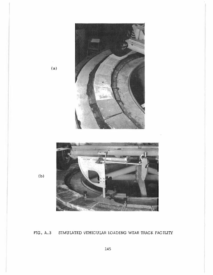
( a)
(b)
FIG. A.3 SIMULATED VEHICULAR WADING WEAR TRACK FACILITY
145
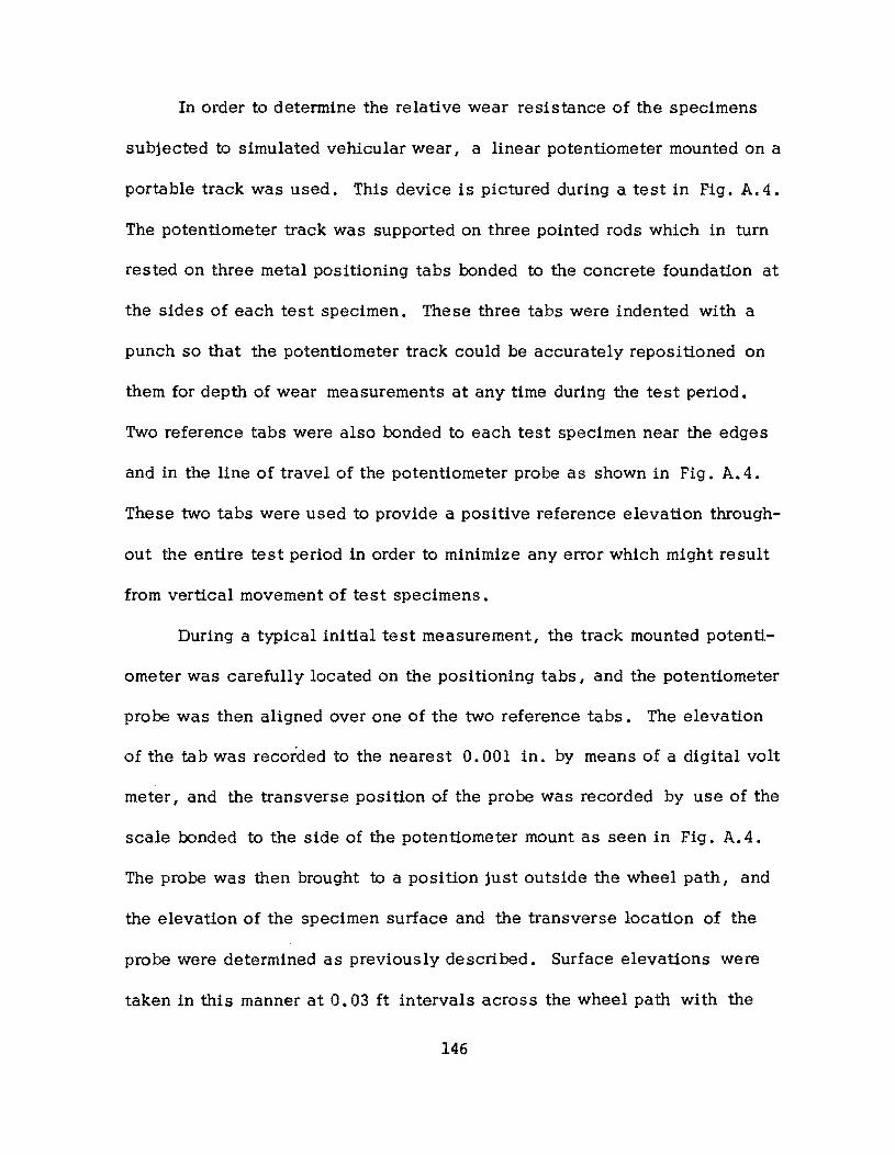
In order to determine the relative wear resistance of the specimens
subjected to simulated vehicular wear, a linear potentiometer mounted on a
portable track was used. This device is pictured during a test in Fig. A. 4.
The potentiometer track was supported on three pOinted rods which in turn
rested on three metal positioning tabs bonded to the concrete foundation at
the sides of each test specimen. These three tabs were indented with a
punch so that the potentiometer track could be accurately repositioned on
them for depth of wear measurements at any time during the test period.
Two reference tabs were also bonded to each test specimen near the edges
and in the line of travel of the potentiometer probe as shown in Fig. A.4.
These two tabs were used to provide a positive reference elevation through
out the entire test period in order to minimize any error which might result
from vertical movement of test specimens.
During a typical initial test measurement, the track mounted potenti
ometer was carefully located on the positioning tabs, and the potentiometer
probe was then aligned over one of the two reference tabs. The elevation
of the tab was recorded to the nearest 0.001 in. by means of a digital volt
meter, and the transverse position of the probe was recorded by use of the
scale bonded to the side of the potentiometer mount as seen in Fig. A.4.
The probe was then brought to a position just outside the wheel path, and
the elevation of the specimen surface and the transverse location of the
probe were determined as previously described. Surface elevations were
taken in this manner at 0.03 ft intervals across the wheel path with the
146
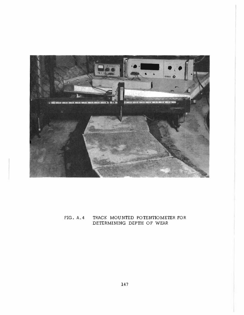
FIG. A.4 TRACK MOUNTED POTENTIOMETER FOR DETERMINING DEPTH OF WEAR
147
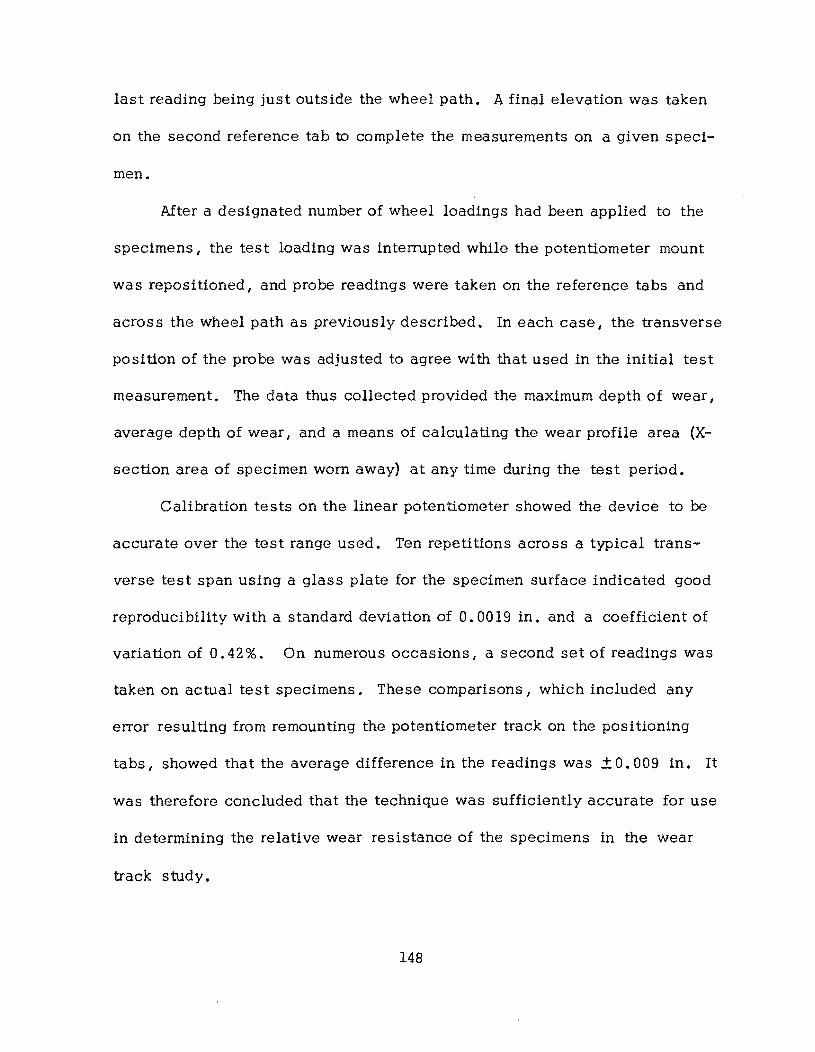
last reading being just outside the wheel path. A final elevation was taken
on the second reference tab to complete the measurements on a given speci-
men.
After a designated number of wheel loadings had been applied to the
specimens I the test loading was interrupted while the potentiometer mount
was repositioned I and probe reading s were taken on the reference tabs and
across the wheel path as previously described. In each case I the transverse
position of the probe was adjusted to agree with that used in the initial test
measurement. The data thus collected provided the maximum depth of wear I
average depth of wear I and a means of calculating the wear profile area (X
section area of specimen worn away) at any time during the test period.
Calibration tests on the linear potentiometer showed the device to be
accurate over the test range used. Ten repetitions across a typical trans
verse test span using a glass plate for the specimen surface indicated good
reproducibility with a standard deviation of 0.0019 in. and a coefficient of
variation of 0.42 %. On numerous occasions I a second set of readings was
taken on actual test specimens. These comparisons, which included any
error resulting from remounting the potentiometer track on the positioning
tabs I showed that the average difference in the readings was ± 0.009 in. It
was therefore concluded that the technique was sufficiently accurate for use
in determining the relative wear resistance of the specimens in the wear
track stud y •
148
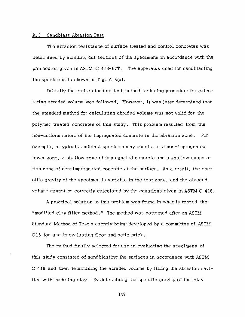
A.3 Sandblast Abrasion Test
The abrasion resistance of surface treated and control concretes was
determined by abrading cut sections of the specimens in accordance with the
procedures given in ASTM C 418-67T. The apparatus used for sandblasting
the specimens is shown in Fig. A. 5{a).
Initially the entire standard test method including procedure for calcu
lating abraded volume was followed. However, it was later determined that
the standard method for calculating abraded volume was not valid for the
polymer treated concretes of this study. This problem resulted from the
non-uniform nature of the impregnated concrete in the abrasion zone. For
example, a typical sandblast specimen may consist of a non-impregnated
lower zone, a shallow zone of impregnated concrete and a shallow evapora
tion zone of non-impregnated concrete at the surface. As a result, the spe
cific gravity of the specimen is variable in the test zone I and the abraded
volume cannot be correctly calculated by the equations given in ASTM C 418.
A practical solution to this problem was found in what is termed the
IImodified clay filler method. II The method was patterned after an ASTM
Standard Method of Test presently being developed by a committee of ASTM
C 15 for use in evaluating floor and patio brick.
The method finally selected for use in evaluating the specimens of
this study consisted of sandblasting the surfaces in accordance with ASTM
C 418 and then determining the abraded volume by filling the abrasion cavi
ties with modeling clay. By determining the specific gravi ty of the clay
149
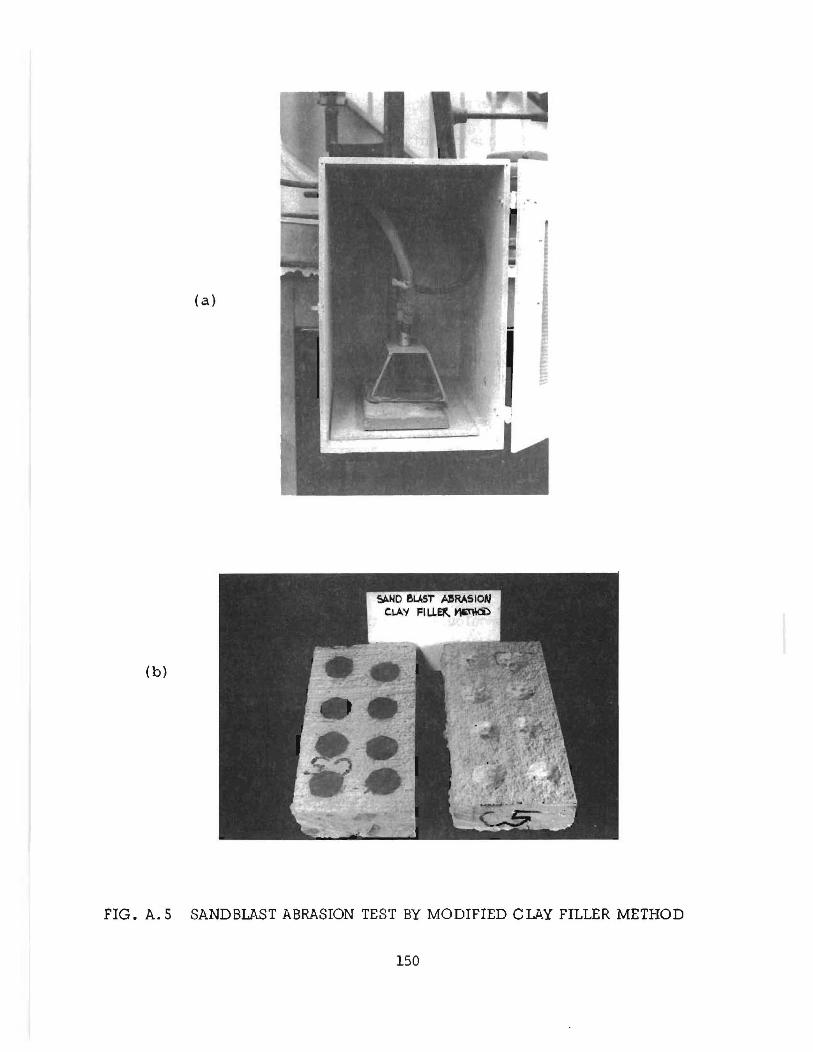
(a)
(b)
FIG. A.S SANDBLAST ABRASION TEST BY MODIFIED CLAY FILLER METHOD
150
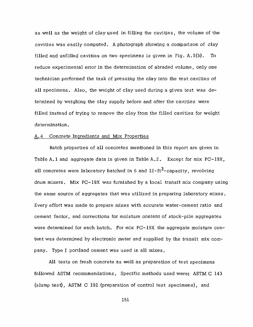
as well as the weight of clay used in filling the cavities I the volume of the
cavities was easily computed. A photograph showing a comparison of clay
filled and unfilled cavities on two specimens is given in Fig. A. 5(b). To
reduce experimental error in the determination of abraded volume I only one
technician performed the task of pressing the clay into the test cavities of
all specimens. Also, the weight of clay used during a given test was de
termined by weighing the clay supply before and after the cavities were
filled instead of trying to remove the clay from the filled cavities for weight
determination.
A.4 Concrete Ingredients and Mix Properties
Batch properties of all concretes mentioned in this report are given in
Table A.l and aggregate data is given in Table A.2. Except for mix PC-19X,
all concretes were laboratory batched in 6 and 12-ft3-capacity I revolving
drum mixers. Mix PC-19X was furnished by a local transit mix company using
the same source of aggregates that was utilized in preparing laboratory mixes.
Every effort was made to prepare mixes with accurate water-cement ratio and
cement factor, and corrections for moisture content of stock-pile aggregates
were determined for each batch. For mix PC-19X the aggregate moisture con
tent was determined by electronic meter and supplied by the transit mix com
pany. Type I portland cement was used in all mixes.
All tests on fresh concrete as well as preparation of test specimens
followed ASTM recommendations. Specific methods used were: ASTM C 143
(slump test) I ASTM C 192 (preparation of control test specimens) I and
151
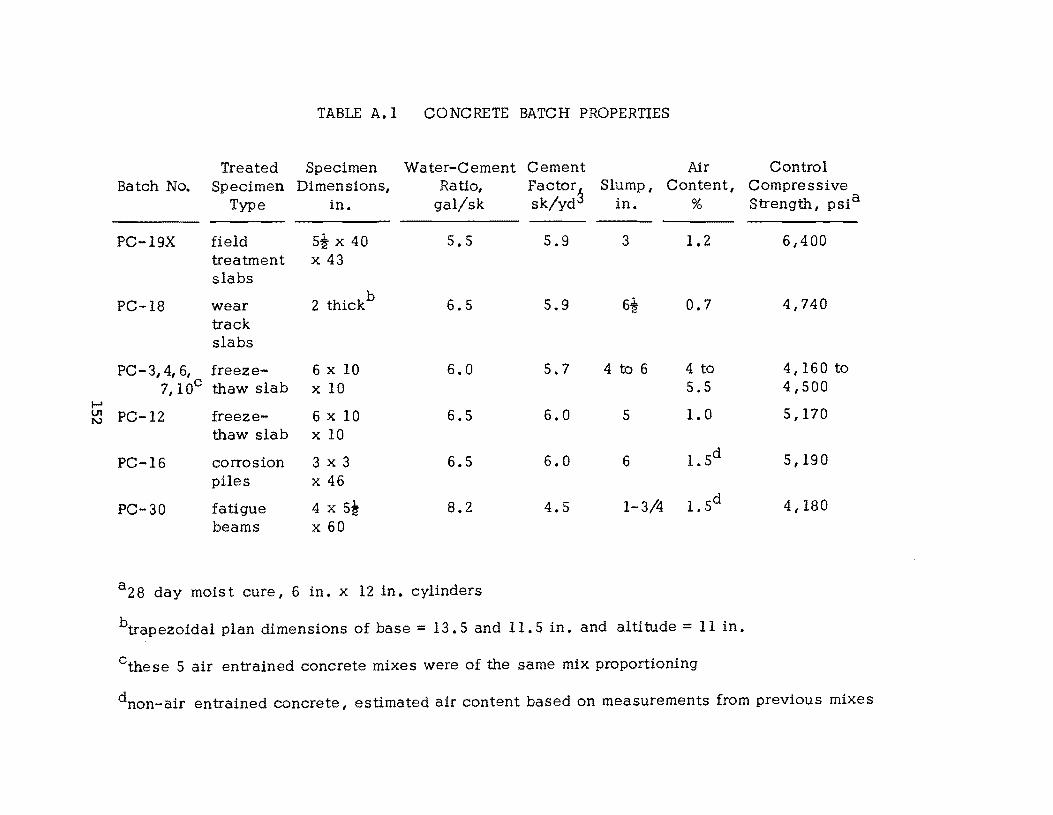
TABLE A.l CONCRETE BATCH PROPERTIES
Treated Specimen Water-Cement Cement Air Control Batch No. Specimen Dimensions, Ratio, Factor~ Slump, Content, Compressive
Type in. gal/sk sk/yd in. % Strength, psia
PC-19X field s! x 40 5.5 5.9 3 1.2 6,400 treatment x 43 slabs
PC-18 wear 2 thickb
6.5 5.9 6! 0.7 4,740 track slabs
PC-3,4,6, freeze- 6 x 10 6.0 5.7 4 to 6 4 to 4,160 to 7,10c thaw slab x 10 5.5 4,500
I-' VI PC-12 freeze- 6 x 10 6.5 6.0 5 1.0 5,170 tv
thaw slab x 10
PC-16 corrosion 3 x 3 6.5 6.0 6 l.Sd 5,190 piles x 46
PC-30 fatigue 4 x si 8.2 4.5 1-3/4 1. Sd 4,180 beams x 60
a 28 day mois t cure I 6 in. x 12 in. cylinders
btrapezoidal plan dimensions of base = 13.5 and 11. 5 in. and altitude = 11 in.
Cthese 5 air entrained concrete mixes were of the same mix proportioning
dnon-air entrained concrete, estimated air content based on measurements from previous mixes
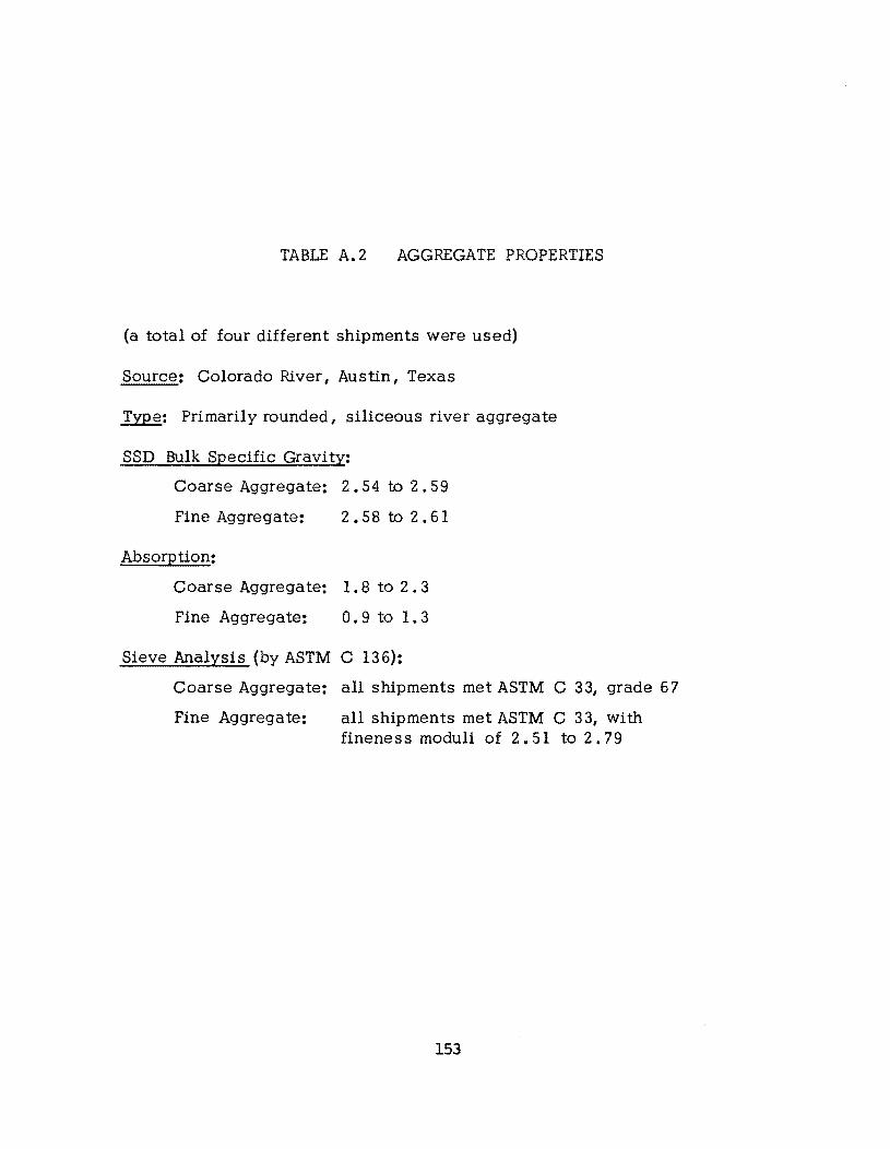
TABLE A.2 AGGREGATE PROPERTIES
(a total of four different shipments were used)
Source: Colorado River, Austin, Texas
~: Primarily rounded, siliceous river aggregate
SSD Bulk Specific Gravity:
Coarse Aggregate: 2.54 to 2.59
Fine Aggregate: 2.58 to 2.61
Absorption:
Coarse Aggregate: 1.8 to 2.3
Fine Aggregate: 0.9 to 1.3
Sieve Analysis (by ASTM C 136):
Coarse Aggregate: all shipments met ASTM C 33, grade 67
Fine Aggregate: all shipments met ASTM C 33, with fineness moduli of 2.51 to 2.79
153
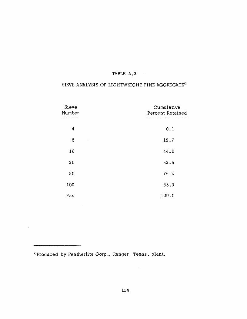
TABLE A.3
SIEVE ANALYSIS OF LIGHTWEIGHT FINE AGGREGATEa
Sieve Cumulative Number Percent Retained
4 0.1
8 19.7
16 44.0
30 62.5
50 76.2
100 85.3
Pan 100.0
aProduced by Featherlite Corp., Ranger I Texas I plant.
154
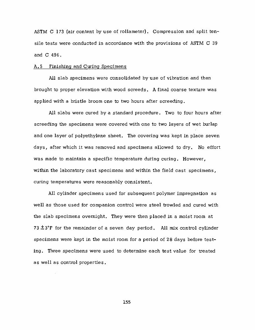
ASTM C 173 (air content by use of rollameter). Compression and split ten
sile tests were conducted in accordance with the provisions of ASTM C 39
and C 496.
A.5 Finishing and Curing Specimens
All slab specimens were consolidated by use of vibration and then
brought to proper elevation with wood screeds. A final coarse texture was
applied with a bristle broom one to two hours after screeding.
All slabs were cured by a standard procedure. Two to four hours after
screeding the specimens were covered with one to two layers of wet burlap
and one layer of polyethylene sheet. The covering was kept in place seven
days I after which it was removed and specimens allowed to dry. No effort
was made to maintain a specifiC temperature during curing. However I
wi thin the laboratory cast specimens and within the field cast specimens I
curing temperatures were reasonably consistent.
All cylinder specimens used for subsequent polymer impregnation as
well as those used for companion control were steel trowled and cured with
the slab specimens overnight. They were then placed in a moist room at
73 + 3°F for the remainder of a seven day period. All mix control cylinder
specimens were kept in the moist room for a period of 28 days before test
ing. Three specimens were used to determine each test value for treated
as well as control properties.
155

!!!!!!!!!!!!!!!!!!!"#$%!&'()!*)&+',)%!'-!$-.)-.$/-'++0!1+'-2!&'()!$-!.#)!/*$($-'+3!
44!5"6!7$1*'*0!8$($.$9'.$/-!")':!
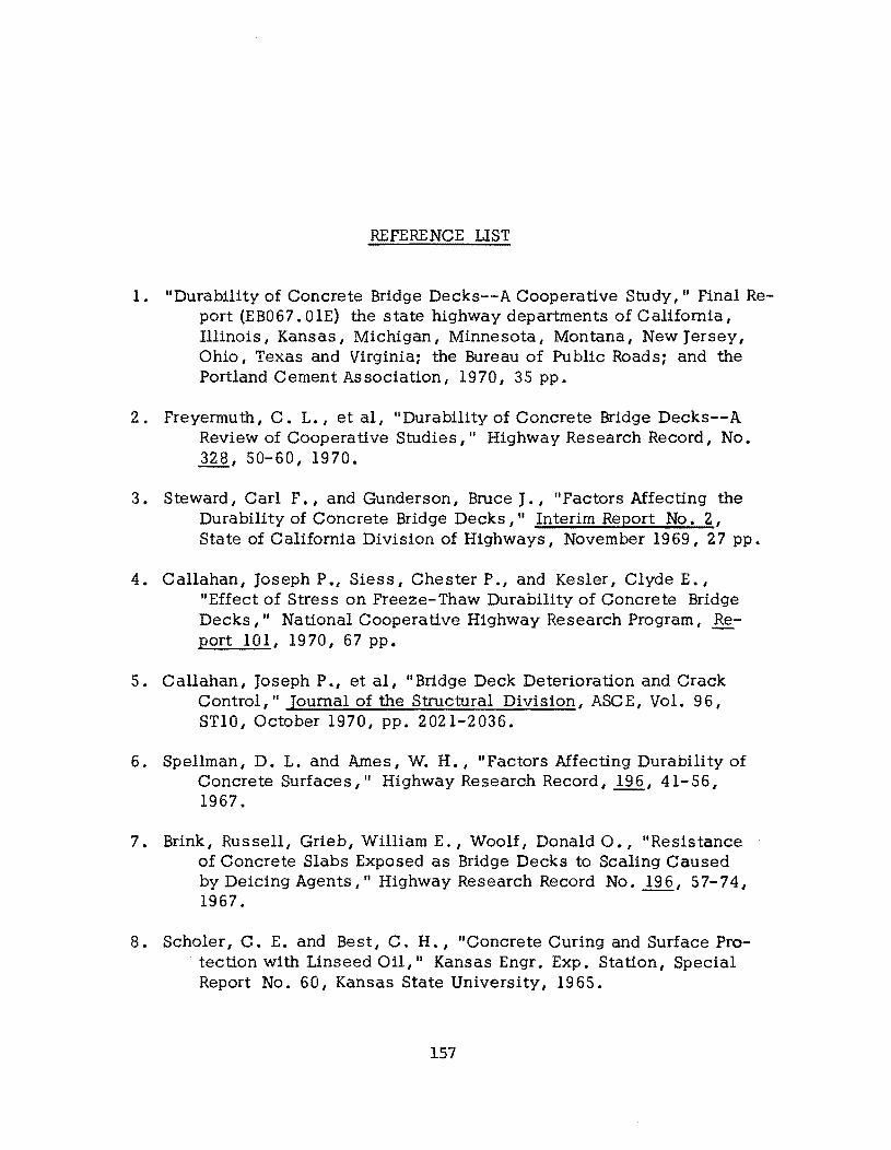
REFERENCE LIST
1. II Durability of Concrete Bridge Decks--A Cooperative Study, II Final Report (EB067. OlE) the state highway departments of California, Illinois, Kansas, Michigan, Minnesota, Montana, New Jersey, Ohio, Texas and Virginia; the Bureau of Public Roads; and the Portland Cement Association, 1970, 35 pp.
2. Freyermuth, C. L., et aI, "Durability of Concrete Bridge Decks--A Review of Cooperative Studies," Highway Research Record, No. 328, 50-60, 1970.
3. Steward, Carl F., and Gunderson, Bruce J., II Factors Affecting the Durability of Concrete Bridge Decks," Interim Report No.2, State of California Division of Highways, November 1969, 27 pp.
4. Callahan, Joseph P., Siess, Chester P., and Kesler, Clyde E. , IIEffect of Stress on Freeze-Thaw Durability of Concrete Bridge Decks," National Cooperative Highway Research Program, Report 101, 1970,67 pp.
5. Callahan, Joseph P., et aI, IIBridge Deck Deterioration and Crack Control," Journal of the Structural Division, ASCE, Vol. 96, STI0, October 1970, pp. 2021-2036.
6. Spellman, D. L. and Ames, W. H., II Factors Affecting Durability of Concrete Surfaces, II Highway Research Record, 196,41-56, 1967.
7. Brink, Russell, Grieb, William E., Woolf, Donald 0., "Resistance of Concrete Slabs Exposed as Bridge Decks to Scaling Caused by Deicing Agents," Highway Research Record No. 196, 57-74, 1967.
8. Scholer, C. E. and Best, C. H., "Concrete Curing and Surface Pro. tection with Linseed 011," Kansas Engr. Exp. Station, Special
Report No. 60, Kansas State University, 1965.
157
9. Spellman, D. L., and Stratfull, R. F., "Chlorides and Bridge Deck Deterioration," Highway Research Record, No. 328,38-49,1970.
10. Cornet, I., Ishikawa T. and Bresler B., liThe Mechanism of Steel Corrosion in Concrete Structures, II Materials Protection, Vol. 7, No. 3, pp. 44-46.
11. Antonino, R. A., "Steel and Corrosion--Some Methods of Protection, II Civil Engineering I Vol. 37, No.2, pp. 32-37.
12. II Methods for Reducing Corrosion of Reinforcing Steel," National Cooperative Highway Research Program, Report 23, 1966, 22 pp.
13. de Bruyn, C. A. L., "Cracks in Concrete and Corrosion of Steel Reinforcing Bars," Proceedings, Symposium on Bond and Crack Formation in Reinforced Concrete (Stockholm 1957), RILEM, Paris, pp. 341- 346.
14, "Protection of Steel in Prestressed Concrete Bridges, II National Cooperative Highway Research Program, Report 90, 1970.
15. Ryell, J. and ChOjnacki, B., "Laboratory and Field Tests on Concrete Sealing Compounds, II Highway Research Record, No. 328, 61-74, 1970.
16. IIEvaluation of Methods of Replacement of Deteriorated Concrete in Structures," Bertram D. Tallamy Associates, National CooperativeHighwayResearchProgram, Report I, Hwy. Res. Board, National Aca of Sc, Nat!. Res. Council, 1963, 56 pp.
17, Kern, K., and Henrichsen, C. F., "Sealing of Cracks in Concrete with Epoxy Resin," Beton-und Stahlbetonban, Vol. 64, No.9, Sept. 1969, pp. 217-18.
18. Rooney, H. A. and Shelly, T. L., IIThin Resinous and Aggregate Overlays on Portland Cement Concrete," California Division of Highways, Research Report No, M & R 635121, June 1969.
19. Geymayer, Helmut G. I HUse of Epoxy or Polyester Resin Concrete in Tensile Zone of Composite Concrete Beams," Army Engineer Waterways Experiment Station, Vicksburg, Mississippi, Report No. AEWES-TH-C69-4, Mar. 1969.
158
20. Steinberg, M.; Dikeou, J. T.; Kukacka, 1. E.; Backstrom, J. E.; Colombo, P.; Rubenstein, S.; Kelsch, J. J.; and Monowitz, B.; Concrete-Polymer Materials« First Topical Report, BNL 50134 (T-509) and USBR General Report No. 41, December 1968.
21. Steinberg, M.; Dikeou, J. T.; Kukacka, L. E.; Backstrom, J. E.; Colombo, P.; Hickey, K. B.; Auskem, A.; Rubenstein, S.; Monowitz, B.; and Jones, C. W., Concrete-Polymer Materials, Second Topical Report, USBR REC-OCE-70-1 and BNL 50218 (T-560), December 1969.
22. Dikeou, J. T.; Steinberg, M.; Cowan, W. C.; Kukacka, L. E.; DePuy, G. W.; Auskem, A.; Smoak, W. G.; Colombo, P.; Wallace, G. B.; Hendrie, J. M.; and Monowi tz, B., ConcretePolymer Materials, Third Topical Report, USBR REC-ERC-71-6 and BNL 50275 (T-602L January, 1971.
23. Dikeou, J. T.; Cowan, W. C.; DePuy, G. W.; Smoak, W. G.; Wallace, G. B.; Steinberg, M.; Kukacka, L. E.: Auskem, A.; Colombo, P.; Hendrie, J. M.; and Monowitz, B., ConcretePolymer Materials, Fourth Topical Report, USBR REC-ERC-72-10 and BNL 50328, January, 1972.
24. Doyle, H. G., Jr., "An Investigation of the Structural Properties of Lightweight and Normal Weight Polymer Concrete," Master's Thesis Presented to the Graduate School at The University of Texas at Austin, May, 1972.
25. Steinberg, M.; Kukacka, L. E.; Colombo, P.; Auskern, A.; Reich, M.; and Pike, R., Concrete-Polymer Materials for Highway Applications, Progre s s Report No. I, BNL 15395, September, 1970.
26. Cordon, William A., "Freezing and Thawing of Concrete--Mechanisms and Control," ACI Monograph No.3, 1966.
27. Houston, James T., Atimtay, E. and Ferguson, Phil M., "Corrosion of Reinforcing Steel Embedded in Structural Concrete, II Center for Highway Research, Univ. of Texas at Austin, Report 1I2-lF I Mar. 1972.
28. Kummer, H. W. and Meyer, W. E., "Tentative Skid-Resistance Requirements for Main Rural Highways,lI National Cooperative Highway Research Program, Report No. E, 1967, 80 pp.
159


![Pre-impregnated Carbon Fibre Reinforced Composite System ... · carbon fibre reinforced polymer (CFRP) for rehabilitating steel structures [1-2, 6-8]. However, most of the research](https://img.pdfslide.net/doc/110x75/5e7026cdd7cc924817290220/pre-impregnated-carbon-fibre-reinforced-composite-system-carbon-fibre-reinforced.jpg)