Embed Size (px)
Citation preview

General rights Copyright and moral rights for the publications made accessible in the public portal are retained by the authors and/or other copyright owners and it is a condition of accessing publications that users recognise and abide by the legal requirements associated with these rights.
Users may download and print one copy of any publication from the public portal for the purpose of private study or research.
You may not further distribute the material or use it for any profit-making activity or commercial gain
You may freely distribute the URL identifying the publication in the public portal If you believe that this document breaches copyright please contact us providing details, and we will remove access to the work immediately and investigate your claim.
Downloaded from orbit.dtu.dk on: Sep 16, 2020
Polymers for Pharmaceutical Packaging and Delivery Systems
Fristrup, Charlotte Juel
Publication date:2010
Document VersionPublisher's PDF, also known as Version of record
Link back to DTU Orbit
Citation (APA):Fristrup, C. J. (2010). Polymers for Pharmaceutical Packaging and Delivery Systems. Technical University ofDenmark.
Polymers for Pharmaceutical Packaging and Delivery Systems
Charlotte Juel Fristrup PhD Thesis
2010
Polymers for Pharmaceutical Packaging and Delivery Systems
Charlotte Juel Fristrup PhD Thesis
2010 DTU Chemical Engineering Department of Chemical and Biochemical Engineering
The Danish Polymer CentreDepartment of Chemical and Biochemical EngineeringTechnical University of DenmarkSøltofts Plads, Building 227DK – 2800 Kgs. LyngbyDenmark Phone: +45 45 25 68 01Web: kt.dtu.dk/english/Research/DPC
Polymers for P
harmaceutical Packaging and D
elivery Systems
Charlotte Juel Fristrup
2010

I
PrefaceThis thesis is the result of my PhD project carried out at the Danish Polymer Centre (DPC) in Department of Chemical and Biochemical Engineering at the Technical University of Denmark (DTU) from 2007 to 2010. The project was cofinanced by DTU, the Danish Agency for Science Technology and Innovation, and the Corporate Research Affairs at Novo Nordisk A/S. At DTU my main supervisor was Professor PhD Søren Hvilsted while Associate Professor PhD Katja Jankova cosupervised me. Research Scientist PhD Rüya Eskimergen Nielsen and Research Scientist PhD Jens Thostrup Bukrinsky were the cosupervisors from Novo Nordisk A/S.
First and foremost I would like to thank Rüya and my former Manager, Niels Bjerrum Thomsen from Department of Materials and Device Characterization at Novo Nordisk A/S for encouraging me to do a PhD and for defining a really interesting project. I am also sincerely grateful to Søren for giving me the opportunity to come back to DPC after three years in industry. Thank you to Katja for being a huge support in discussions of the experimental work but also for taking care of Xenia while her parents had to work. You were very courageous when you went with us on a four-wheel drive trip for 16 hours after travelling 30 hours to Australia. It was more than I could endure. I would also like to thank Jens for making contact with highly qualified people at Novo Nordisk A/S when needed. Moreover, our discussions especially in the last part of the project have been of great value to me. I have really enjoyed the knowledge exchange which I have had with all four advisors during the PhD studies. Our meetings have always been very useful although I sometimes had to remind you what was on the agenda.
At Novo Nordisk A/S I would like to acknowledge Technician Dorrit Eggert Larsen and Technician Kirsten Larsen for assistance with the HPLC analyses. Technician Anne Ahrensberg Jensen is thanked for the training in the Thioflavin T test, also thanks to Annette Behrens for carrying out the metal analysis. Technician Helle Markussen Nordholm and Team Manager Søren Johnsen from the microscopy group at FeF Chemicals A/S are acknowledged for assistance in developing a suitable method for the investigations of insulin adsorption or repellence with confocal fluorescence microscopy. Furthermore, the whole microscopy group is thanked for providing scanning electron microscopy images. At Risø DTU I would like to thank Lene Hubert for the X-ray photoelectron spectroscopy results and P.S. Ramanujam for the atomic force microscopy analyses. Monika Butrimaité did her master thesis in the group at DPC and is acknowledged for performing the modifications with one of the monomers (PEGMA) in the first stability study as well as assisting with the setup of the study in question. Laboratory coordinator Kim Chi Szabo at DPC is thanked for carrying out the thermo gravimetric analyses and the size exclusion chromatography analyses.

II
I wish to thank all my colleagues at DPC for my time there – I am glad, I came back! Thank you to everyone at Novo Nordisk A/S who has taken part in my project in one way or another. To my office mates, especially Anders and Irakli thank you for our many discussions and for creating an inspiring atmosphere. My critical proof readers and advisors, Søren and Katja are thanked for their comments and corrections. Last but not least I would like to thank my husband, Peter for his support and the work he has carried out on the house. I also appreciate the pictures of insulin aspart which you have made for the front page.
Kgs. Lyngby, November 30th 2010.
Charlotte Juel Fristrup
III
Synopsis Selection of polymer materials which will be exposed to protein drugs in either containers or medical devices is often very challenging due to the demands on the polymers. Suitable polymer materials should comply with requirements like compatibility with proteins, sterilisability, good barrier properties towards preservatives, and no toxic leachables. The basis of the thesis was hydrophilization of commercially available hydrophobic polymer materials in order to inhibit non-specific fouling. Hydrophilic polymeric grafts were prepared by Surface-Initiated Atom Transfer Radical Polymerization (SI-ATRP) from commercially available polymers. Initially, poly(ether ether ketone) (PEEK) films were applied as a model system to demonstrate that hydrophilization of a substrate could be obtained by SI-ATRP. PEEK has ketone groups which can be reduced to hydroxyl groups and used for anchoring of 2-bromoisobutyrate initiating sites. Each modification step of PEEK as well as grafting of poly(ethylene glycol) methacrylate (PEGMA) was followed and confirmed by Attenuated Total Reflectance Fourier Transform Infrared (ATR-FTIR) spectroscopy, water contact angle (WCA) measurements, and Thermal Gravimetric Analysis. X-ray Photoelectron Spectroscopy also confirmed the presence of the poly(PEGMA) grafts on the PEEK surface by comparing the C/O ratio and the chemical composition after each modification step. The surface topography was evaluated by Atomic Force Microscopy.
Polypropylene (PP) is one of the polymeric materials of interest for pharmaceutical packaging and delivery systems. Confocal fluorescence microscopy studies and stability studies with insulin aspart (AspB28 insulin) were conducted to evaluate the impact of modified PP compared to unmodified PP. In contrast to PEEK, PP did not contain any functional groups which could easily be used for attachment of initiating sites for SI-ATRP. An UV initiator, benzophenonyl 2-bromoisobutyrate was synthesized from 4-hydroxybenzophenone and 2-bromoisobutyryl bromide. Irradiation ( =365 nm) of the UV initiator applied to PP plates resulted in formation of covalent C-C bonds between the photoactive benzophenone and the aliphatic C-H groups on the PP surface. The experimental work was carried out in two rounds. Grafts of poly(PEGMA) and N,N-dimethylacrylamide (DMAAm), respectively were prepared by conventional SI-ATRP from PP and used in the first experimental round. In order to decrease the amount of catalyst residual in the modified materials, activator regenerated by electron transfer (ARGET) SI-ATRP was applied in the second experimental round. Two poly(ethylene glycol)methyl ether methacrylate (MPEGMA) monomers with 4 and 23 ethylene oxide units in the side chain were grafted from PP by ARGET SI-ATRP. The hydrophilic grafts engineered by either conventional or ARGET SI-ATRP were characterized by ATR-FTIR and WCA measurements. Insulin adsorption studies with confocal fluorescence microscopy showed that only the poly(PEGMA) coating was able to repel labelled AspB28 insulin at the present conditions. The first stability study revealed an inverse correlation

IV
between AspB28 insulin related impurities and higher molecular weight proteins and the same trend seemed to be present in the second study. PP coated with poly(DMAAm) resulted in a poor chemical stability and a significantly improved physical stability of AspB28 insulin compared with unmodified PP. Increased physical stability was determined as a lower tendency to form fibrils. Additionally, observations like higher content of AspB28 insulin related impurities, lower phenol concentration, and presence of copper were made for the poly(DMAAm) coating. Scanning Electron Microscope analysis was applied to visualize inhibition of AspB28 insulin fibrillation or differences in the fibrillar structures which caused lower fluorescence intensities in the Thioflavin T test. The second stability study has until know been going on for 4 months and the poly(MPEGMA) coatings have not shown a significant change in the AspB28 insulin stability compared with unmodified PP. The results from the poly(PEGMA) coating in the first stability study after 8 months of testing looked very promising with respect to the stability of AspB28 insulin in comparison with the data from unmodified PP.
V
ResuméValg af polymermaterialer til beholdere eller medicinske artikler, som udsættes for proteinholdige lægemidler, er ofte meget udfordrende pga. kravene til polymererne. Egnede polymermaterialer skal overholde krav som f.eks. kompatibilitet med proteinerne, steriliserbarhed, gode barrieregenskaber overfor konserveringsmidler og ingen giftige lækstoffer. Afhandlingen tog udgangspunkt i at gøre kommercielt tilgængelige hydrofobe polymermaterialer hydrofile for at undgå adsorption af proteiner. Hydrofile polymerkæder blev fremstillet ved ”Surface-Initiated Atom Transfer Radical Polymerization” (SI-ATRP) fra kommercielt tilgængelige polymerer. Poly(ether ether keton) (PEEK) film blev indledningsvis anvendt som modelsystem til at vise, at et materiale kan gøres mere hydrofilt ved SI-ATRP. PEEK har ketongrupper, som kan reduceres til hydroxygrupper og dernæst bruges til fastgørelse af 2-bromoisobutyrat initiatorgrupper. Alle trinene under modifikationen af PEEK såvel som polymerisation af poly(ethylen glycol) methacrylat (PEGMA) blev fulgt og bekræftet med ”Attenuated Total Reflectance Fourier Transform Infrared” (ATR-FTIR) spektroskopi, kontaktvinkelmålinger med vand og ”Thermal Gravimetric Analysis”. ”X-ray Photoelectron” spektroskopi bekræftede også tilstedeværelsen af poly(PEGMA) kæder på PEEK overfladen ved at sammenligne C/O forholdet og den kemiske sammensætning efter hvert modifikationstrin. Overfladeruheden blev vurderet med ”Atomic Force Microscopy”. Polypropylen (PP) var et af de materialer, der var interessante som emballage til farmaceutiskindustri og til medicinske artikler. For at evaluere indflydelsen af modificeret PP sammenlignet med ikke-modificeret PP blev der opsat studier med konfokal fluorescensmikroskopi samt stabilitetsstudier med insulin aspart (AspB28 insulin). PP indeholder i modsætning til PEEK ikke nogle funktionellegrupper, som let kan anvendes til fastgørelse af initiatorgrupper til SI-ATRP. UV-initiatoren benzophenonyl 2-bromoisobutyrat blev syntetiseret fra 4-hydroxybenzophenon og 2-bromoisobutyryl bromid. Bestråling ( =365 nm) af PP pladerne med den påførte UV-initiator resulterede i dannelse af kovalente C-C bindinger imellem den fotoaktive benzophenon og de alifatiske C-H grupper på PP overfladen. Det eksperimentelle arbejde blev udført af to omgange. Kæder af henholdsvis poly(PEGMA) og N,N-dimethylacrylamid (DMAAm) blev fremstillet ved traditionel SI-ATRP fra PP og brugt i den første eksperimentelle runde. For at mindske restmængder af katalysator i de modificerede materialer blev ”activator regenerated by electron transfer” (ARGET) SI-ATRP anvendt i den anden eksperimentelle runde. To poly(ethylen glycol)methyl ether methacrylat (MPEGMA) monomerer med henholdvis 4 og 23 ethylenoxid enheder i sidekæden polymeriseret fra PP ved ARGET SI-ATRP. De hydrofile polymerkæder, som enten var fremstillet ved traditionel eller ARGET SI-ATRP, blev karakteriseret med ATR-FTIR og kontaktvinkelmålinger med vand. Insulin adsorptionsforsøg med konfokal fluorescensmikroskopi viste, at det kun var poly(PEGMA) coatningen, som
VI
var i stand til at afvise mærket AspB28 insulin. Det først stabilitetsforsøg viste, at der var en omvendt korrelation imellem AspB28 insulin relaterede urenheder samt proteiner med højere molekylvægt, og den samme trend er sandsynligvis til stede i det andet stabilitetsforsøg. PP coatet med poly(DMAAm) resulterede i forringet kemisk stabilitet og betydelig forbedret fysisk stabilitet af AspB28 insulin, når der sammenlignes med ikke-modificeret PP. Forbedret fysisk stabilitet opnås, såfremt tendensen til at danne fibriller forringes. Desuden blev der for poly(DMAAm) coatningen observeret et højere indhold af AspB28 insulin relaterede urenheder, lavere phenolkoncentration og tilstedeværelse af kobber. ”Scanning Electron Microscope” analyse blev anvendt til at visualisere hæmningen af AspB28 insulin fibrillering samt forskelle i fibrilstrukturen, som forårsagede lavere fluorescensintensiteter i Thioflavin T testen. Det andet stabilitetsforsøg har indtil nu været i gang i 4 måneder og poly(MPEGMA) coatningerne har endnu ikke vist en signifikant ændring i stabiliteten for AspB28 insulin sammenlignet med ikke-modificeret PP. Resultaterne efter 8 måneder for poly(PEGMA) coatningen i det første stabilitetsforsøg ser meget lovende ud med hensyn til stabiliteten af AspB28 insulin, hvis der sammenlignes med data for ikke-modificeret PP.

1
Contents Preface .................................................................................................. I
Synopsis ............................................................................................. III
Resumé ............................................................................................... V
List of Abbreviations .......................................................................... 3
1 Background ...................................................................................... 5 1.1 Selection of polymers for pharmaceutical packaging and delivery
systems ................................................................................................ 5 1.2 Scope ................................................................................................... 6 1.3 Thesis outline ...................................................................................... 6
2 Polymer and drug compatibility ..................................................... 9 2.1 Protein rejection or adsorption ............................................................ 9 2.2 PEG and PEG-like coatings .............................................................. 10 2.3 Characteristics of non-fouling coatings ............................................. 10
3 Surface modification ..................................................................... 13 3.1 How to apply a polymer coating to the surface ................................. 13
3.1.1 Grafting from or grafting onto ......................................... 14
4 Surface-Initiated Atom Transfer Radical Polymerization ........... 17 4.1 Surface-anchored initiators ............................................................... 18 4.2 Lower amount of catalyst .................................................................. 19
5 Biofunctional coatings .................................................................. 21 5.1 Inhibition of non-specific fouling ..................................................... 24
5.1.1 General examples of non-fouling polymeric grafts ......... 24 5.1.2 Non-fouling grafts for separation of proteins .................. 27
6 Characterization methods ............................................................. 29 6.1 Characterization of polymer grafts .................................................... 29 6.2 Methods to demonstrate inhibition of fouling ................................... 31
7 Model system ................................................................................. 33 7.1 Results and discussion ....................................................................... 33 7.2 Conclusions ....................................................................................... 39
8 Hydrophilization of polypropylene ............................................... 41 8.1 Materials and methods ...................................................................... 42
8.1.1 Chemicals ........................................................................ 42 8.1.2 ARGET SI-ATRP of M4PEGMA ................................... 42
2
8.1.3 ARGET SI-ATRP of M23PEGMA .................................. 43 8.1.4 Visualization of the surface modifications ...................... 43 8.1.5 Scanning electron microscope analysis ........................... 45
8.2 Modification of polypropylene .......................................................... 45 8.2.1 Adsorption studies with labelled insulin ......................... 48 8.2.2 Conclusions ..................................................................... 52 8.2.3 Chemical and physical stability of insulin ....................... 52 8.2.4 Conclusions ..................................................................... 62
9 Concluding remarks ...................................................................... 65
10 Outlook ......................................................................................... 66
11 References ................................................................................... 67
Appendices
Appendix A
Appendix B
Appendix C
Appendix D
3
List of Abbreviations AA Acrylic acid AAm Acrylamide Aβ Amyloid-β AFM Atomic force microscopy AGET Activators generated by electron transfer ARGET Activator regenerated by electron transfer AsA L-Ascorbic acid AspB28 insulin Insulin aspart ATR-FTIR Attenuated total reflectance fourier transform infrared ATRP Atom transfer radical polymerization tBA tert-Butyl acrylate tBAEMA 2-(tert-Butylamino)ethyl methacrylate Bipy 2,2’-Bipyridine BP-i-BuBr Benzophenonyl bromoisobutyrate Br-i-BuBr 2-Bromoisobutyryl bromide BSA Bovine serum albumin CBMA 2-Carboxy-N,N-dimethyl-N-(2’-
methacryloyloxyethyl)ethanaminium inner salt CFRP Conventional free radical polymerization o-DCB ortho-Dichlorobenzene DEAEMA 2-(Diethylamino)ethyl methacrylate DMAAm N,N-Dimethylacrylamide DMAEMA 2-(N,N-Dimethylamino)ethyl methacrylate DMDP 4,4’-Dimethyl-2,2’-dipyridyl DMF N,N-Dimethyl formamide DMSO Dimethyl sulfoxide DPC Danish polymer centre DTU Technical university of Denmark DVB Divinylbenzene EDC 1-Ethyl-3-(3-dimethylaminopropyl)-carbodiimide
hydrochloride EO Ethylene oxide FESEM Field emission scanning electron microscope GMA Glycidyl methacrylate GMMA Glycerol monomethacrylate HEMA 2-Hydroxyethyl methacrylate HMTETA 1,1,4,7,10,10-Hexamethyltriethylenetetramine HMWP Higher molecular weight proteins HPLC High performance liquid chromatography ICP-OES Inductive coupled plasma optical emission spectroscopy LCST Lower critical solution temperature MAAS Methacrylic acid sodium salt MAIpGlc 3-O-Methacryloyl-1,2:5,6-di-O-isopropylidene-D-
glucofuranose

4
MCF Mesostructured cellular foam Me4Cyclam 1,4,8,11-Tetraazacyclotetradecane MEMA 2-Methoxyethyl methacrylate Me6TREN Tris(2-(dimethylamino)ethyl)amine MMA Methyl methacrylate MPC 2-Methacryloyloxyethyl phosphorylcholine MPDSAH (3-(Methacryloylamino)propyl)-dimethyl(3-sulfopropyl)
ammonium hydroxide MPEG Monomethoxy poly(ethylene glycol) MPEGMA Poly(ethylene glycol)methyl ether methacrylate NIPAAm N-Isopropylacrylamide NMP 1-Methyl-2-pyrrolidione NP Nanoparticle PDMS Poly(dimethylsiloxane) PEEK Poly(ether ether ketone) PEG Poly(ethylene glycol) PEGMA Poly(ethylene glycol) methacrylate PET Poly(ethylene terephthalate) PI Polyimide PMDETA 1,1,4,7,7-Pentamethyldiethylenetriamine PP Polypropylene pp-MPEGMA plasma-polymerized poly(ethylene glycol)methyl ether
methacrylate PS Polystyrene PTFE Poly(tetrafluoroethylene) PVBC Poly(4-vinylbenzyl chloride) PVDF Poly(vinylidene fluoride) QCM Quartz crystal microbalance RP Reverse phase SAIs Surface anchored initiators SBMA Sulfobetaine methacrylate SEC Size exclusion chromatography SEM Scanning electron microscope SI-ATRP Surface-initiated atom transfer radical polymerization SP (-)-Sparteine SPM 3-Sulfopropyl methacrylate potassium salt SPR Surface plasmon resonance TEA Triethylamine TGA Thermal gravimetric analysis THF Tetrahydrofuran UV Ultraviolet 2-VP 2-Vinylpyridine 4-VP 4-Vinylpyridine WCA Water contact angle XPS X-ray photoelectron spectroscopy
5
1 Background Storage and administration of protein drugs are imperative in modern society. Glass is used for storage of protein drugs; however, the material is fragile and does not offer design of freedom for products in a mass production. If polymers could replace glass it will make a difference. Polymers will especially be suitable for devices with demands for greater dose accuracy and minimum waste of precious drugs.
1.1 Selection of polymers for pharmaceutical packaging and delivery systems
Polymeric materials in contact with a drug product should fulfil a number of requirements besides the typical requirements like adequate mechanical properties and suitability for mass production. The polymer should be chemically resistant towards the excipients of the drug product. Moreover, it should be suitable for sterilisation, have good barrier properties towards water, preservatives and preferably also gases. It should comply with the existing regulations regarding the amount and toxicity of leachables. The number of commercially available polymer materials which can be used is rather limited. Moreover, the polymeric materials are typically hydrophobic, which is known to be a disadvantage with respect to protein adsorption.
In the field of diabetes treatment, compatibility of the polymer materials with insulin is extremely important. Compatibility between a polymer and insulin covers for instance good chemical and physical stability of insulin, low level of non-toxic leachables, and inhibition of insulin adsorption. In order to simplify the studies in this thesis leachables analysis has been omitted. Surface characteristics are known to influence the amount of adsorbed protein per unit surface area, the adsorption kinetics,1,2 and the rate of fibrillation.3,4 It has been proposed that the insulin monomer would undergo conformational changes upon adsorption to a hydrophobic surface and may thereby possibly initiate a fibrillation process.5-8 The following mechanism has been proposed: Monomeric insulin is partially unfolded upon adsorption and can either refold to the native state or combine with other unfolded monomers. Nucleation is initiated and intermediate aggregates are formed. The intermediates can either fall apart or interact with unfolded species. When the intermediates reach a sufficient size, the surface area is large enough to stabilize the structure and combination with native molecules occurs. The slow formation of stable intermediates explains the lag phase which is often observed in insulin fibrillation experiments.5,7 Furthermore, it has been indicated that the monomers have a higher tendency to adsorb to hydrophobic surfaces than the dimers and hexamers as the hydrophobic surfaces of the monomers are shielded when dimers or hexamers are formed.5 Based on studies with hydrophilized chromium and titanium surfaces it seems like insulin dimers and hexamers are present at the hydrophilic surface and probably electrostatically bound to the surface. The studies also include a monomeric

6
insulin which does not adsorb to the hydrophilic surfaces.9,10 The insulin analogue, insulin aspart (AspB28 insulin) in the thesis is characterized by a significantly reduced tendency to form dimers and hexamers. AspB28 insulin was also chosen as it is of interest for e.g. continuous subcutaneous infusion and promising results in simulated use in infusion pumps have been reported.11
1.2 Scope The aim of the PhD project was to modify commercially available thermoplastic materials with a polymeric material in order to expand the utilisation of the polymers for pharmaceutical packaging and delivery systems. The primary goal was to improve the compatibility with insulin which was assessed by evaluating the chemical and physical stability of insulin as well as the ability to prevent adsorption of insulin. Secondary, long-term stability of insulin and thus the polymeric materials was important for the applications. Therefore, accelerated insulin stability studies at elevated temperatures as well as real-time studies were conducted. Moreover, only synthesis procedures which will result in firmly anchored polymeric layer should be considered. Surface-Initiated Atom Transfer Radical Polymerization (SI-ATRP) was chosen to prepare hydrophilic grafts from the thermoplastic materials. In addition to the covalent bond to the surface, the method offered versatility in selection of monomers, low polymerization temperatures, aqueous or methanolic media, and the possibility to obtain well-defined structures.
1.3 Thesis outline The thesis briefly introduces the requirements and the characteristics of the polymer materials, which is needed to inhibit protein adsorption (Chapter 2). The techniques available for surface modification of organic/polymeric substrates are compared in Chapter 3. SI-ATRP was selected to graft hydrophilic polymers from polymeric substrates. Chapter 4 introduces SI-ATRP and how initiating sites can be prepared on organic/polymeric substrates. Moreover, two relatively new catalytical methods, activators generated by electron transfer (AGET) and activator regenerated by electron transfer (ARGET) are outlined in which lower amount of catalyst is used in combination with a reducing agent. Many of the coatings prepared by SI-ATRP have been used for biological applications and proven to have a certain biofunctionality. Most of SI-ATRP studies in literature with proven biofunctionality for the grafts have been made on inorganic/metallic substrates; therefore, all types of surfaces combined with the applied monomers will be shown in Chapter 5. However, the literature survey in Chapter 5 is only on biofunctional coatings which inhibit non-specific fouling. The other biofunctionalitites which include immobilization of biomolecules, adsorbents for proteins or cells, antibacterial activity, and encapsulation of
7
drugs can be found in the review article Appendix A. The characterization methods available for grafting from organic/polymeric substrates are very limited compared with inorganic/metallic substrates. The problem is highlighted along with a list of available techniques in Chapter 6. Initially, a model system consisting of surface functionalized poly(ether ether ketone) (PEEK) was applied. The hydrophilized PEEK had two applications, protein repellence and metallisation. Only the expected ability to repel proteins will be discussed in Chapter 7. The article in Appendix B contains both applications of the modified PEEK. Two stability studies were conducted with unmodified and modified polypropylene (PP) plates immersed in insulin. In the first study PP plates were modified with two types of hydrophilic grafts prepared by SI-ATRP. The second study was displaced 10 months from the first study; therefore, it was decided to implement experience from the first study and lower the amount of catalyst. Three different monomers were applied for ARGET SI-ATRP from PP in the second study. The results from two of them are included in Chapter 8 whereas the work with the third is confidential and filed July 15th 2009 in a patent application, PCT Application No. PCT/DK2010/050187. Chapter 8 also contains results from the first stability study and investigations with confocal fluorescence microscopy of insulin rejection or adsorption on modified and unmodified PP plates. The experimental work from the modification of PEEK and the work carried out in the first stability study are described in the articles Appendix B-D. The experimental procedures from the second stability study are outlined in Chapter 8. The surface modifications and most of the polymer characterization were made at the Danish Polymer Centre, DTU. Atomic force microscope analysis and X-ray Photoelectron Spectroscopy (XPS) were performed by employees at Risø DTU. High Performance Liquid Chromatography (HPLC) analysis was carried out in close collaboration with two technicians at Novo Nordisk A/S in Hillerød. The Thioflavin T (ThT) test was performed at Novo Nordisk A/S in Måløv. Metal analysis by Inductive Coupled Plasma Optical Emission Spectroscopy (ICP-OES) was made by Team Leachables & Metals from Chemistry Manufacturing Control Analytical Support at Novo Nordisk A/S. The adsorption studies with labelled insulin were carried out in close collaboration with the microscopy group at FeF Chemicals A/S. The microscopy group also supplied all the images from the Scanning Electron Microscope (SEM) analyses. Appendix A. C.J. Fristrup, K. Jankova, and S. Hvilsted, Surface-initiated atom transfer radical polymerization – a technique to develop biofunctional coatings, Soft Matter, 5 (2009) 4623-4634. Appendix B. C.J. Fristrup, K. Jankova, and S. Hvilsted, Hydrophilization of poly(ether ether ketone) films by surface-initiated atom transfer radical polymerization, Polym. Chem., 1 (2010) 1696-1701.

8
Appendix C. C.J. Fristrup, K. Jankova, R. Eskimergen, J.T. Bukrinsky, and S. Hvilsted, Protein repellent hydrophilic grafts prepared by surface-initiated atom transfer radical polymerization from polypropylene, Polym. Chem., 3 (2012) 198-203. Appendix D. C.J. Fristrup, K. Jankova, R. Eskimergen, J.T. Bukrinsky, and S. Hvilsted, Stability of AspB28 insulin exposed to modified and unmodified polypropylene, Protein Peptide Lett., 22 (2015) 635-643.
9
2 Polymer and drug compatibility The definition of compatibility from McGraw-Hill Encyclopedia of Science & Technology Online is as follows: “The ability of two or more materials, substances, or chemicals to be used together without ill effect” Control of the interactions between the polymer and the drug product formulation (in this case a protein formulation) is needed in order to obtain the compatibility. One way to attain compatibility is to reduce the extent of protein adsorption. Different approaches can be chosen to minimize protein adsorption. One method is passivation with sacrificial cheap proteins which are adsorbed at the surface in order to avoid adsorption of other proteins. A second method, which often is not feasible, is to stabilize the formation of the hydrophobic core of the protein by e.g. disulfide bonds. Finally, the approach from this project is stabilization of hydration at the surface by a hydrophilic coating.
2.1 Protein rejection or adsorption Folding of proteins is controlled by non-covalent interactions like electrostatic, hydrogen bonding, van der Waals, hydrophobic, and acid/base. The same type of interactions controls the protein and surface interactions. The process involved in protein rejection or adsorption is energy-driven as well as dynamic and it can be described by the change in Gibbs free energy, ΔG. ΔG= ΔH – T·ΔS If ΔG is positive a repulsive force is present between the surface and the liquid protein layer. On the other hand, a negative ΔG will generate an attractive force which will result in protein adsorption. When an aqueous protein solution is exposed to a hydrophobic surface dehydration (release of water) occurs and the change in Gibbs free energy becomes negative as the entropy, ΔS increases.12 Moreover, hydrophobic forces between the surface and the hydrophobic core of the protein will give a negative gain in enthalpy, ΔH, and contribute to the negative ΔG. A protein adsorbed to the hydrophobic surface is likely to denature by unfolding of the protein. The unfolding i.e. rearrangements in the protein structure will increase the enthalpy; however, the enthalpy for the overall protein adsorption process is negative. To sum up protein adsorption at a hydrophobic surface is an energetically favourable and irreversible process.13 Repulsion of proteins at hydrophilic surfaces is also a minimum interfacial energy phenomenon. In theory protein adsorption is less likely to appear as the
10
interfacial energy with water approaches zero. Proteins close to a low interfacial energy surface should not be under greater influence from the surface than from the bulk solution.12 However, all surfaces are to some extend hydrophobic compared to water itself. For that reason, all surfaces exhibit some adsorption and denaturation of proteins.13 A poly(ethylene glycol) (PEG) coating in aqueous solution is one of those materials which is able to resist protein adsorption. Some possible explanations to what makes PEG so unique is outlined below.
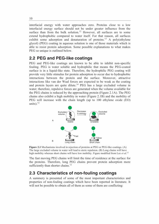
2.2 PEG and PEG-like coatings PEG and PEG-like coatings are known to be able to inhibit non-specific fouling. PEG is water soluble and hydrophilic that means the PEG-coated surface is in a liquid-like state. Therefore, the hydrophilic PEG coating will provide very little stimulus for protein adsorption to occur due to hydrophobic interactions between the protein and the surface. Moreover, attractive interactions like van der Waal forces are expected to be weak as the coating and protein layers are quite dilute.14 PEG has a large excluded volume in water; therefore, repulsive forces are generated when the volume available for the PEG chains is reduced by the approaching protein (Figure 2.1A). The PEG chains also exhibit a high mobility in water (Figure 2.1B) and the mobility of PEG will increase with the chain length (up to 100 ethylene oxide (EO) units).12
Excluded volume
Excluded volume
Decrease in entropy
Stable Unstable
Long chain Short chain
FastSlow
A
B
Figure 2.1 Mechanisms involved in rejection of proteins at PEG or PEG-like coatings. (A) The large excluded volume in water will lead to steric repulsion. (B) Long chains will have high mobility whereas short chains will have low mobility. Figure modified from Lee et al.12
The fast moving PEG chains will limit the time of residence at the surface for the proteins. Therefore, long PEG chains prevent protein adsorption more sufficiently than shorter chains.12
2.3 Characteristics of non-fouling coatings A summery is presented of some of the most important characteristics and properties of non-fouling coatings which have been reported in literature. It will not be possible to obtain all of them as some of them are conflicting:

11
Hydrophilic and highly hydrated Branched polymer architectures High grafting density Chain length Flexible Firmly anchored Uncharged surfaces → no electrostatic interactions Methoxy end groups rather than hydroxyl
Hydrophilicity and solubility in water have been mentioned before as essential properties of the polymer coating. The architecture of the polymer coating is very crucial for the ability to suppress non-specific fouling. A branched polymer architecture (Figure 2.2A) is one feasible structure for a non-fouling coating. Another possibility is a high grafting density which means that the polymer chains are attached close to each other (Figure 2.2B). A study with star shaped PEG and linear PEG has shown excellent repulsion of both insulin and lysozyme when the PEG coating had a high surface coverage (branched structure or high grafting density). However, a coating with longer PEG chains resulted in a lower grafting density (Figure 2.2C) which only inhibited adsorption of the larger lysozyme and not of the smaller insulin.15
A B C Figure 2.2 A branched polymer coating (A) and a polymer coating with high grafting density (B) will inhibit non-specific fouling; if the grafting density is insufficient some fouling may occur (C); the red proteins are lysozyme and the green are insulin. Figure modified from Groll et al.15 Good non-fouling properties of coatings are often not only ascribed to the chain length. Most studies, which investigate the influence of the chain length, assume high enough grafting density. Prime and Whitesides16 discovered that for physical adsorbed PEG coatings >2 EO units were sufficient to suppress fouling. Others have reported 35-100 EO units for different PEG-containing coatings in order to obtain efficient repulsion.17-19 Flexibility of the polymer coating is related to the chain length of the polymer grafts and it will increase with the chain length. Moreover, bulky side groups will decrease the flexibility; especially, if they are incompatible with aqueous solutions as water will be hindered sterically. The coating should be firmly anchored to the surface to have prolonged stability. In case of adsorption of a coating instead of a covalent bonding interfacial exchange could happen, this is replacement

12
of the adsorbed polymer layer by protein. If uncharged coatings are applied protein adsorption due to electrostatic interactions can be avoided, regardless of the isoelectric point of the protein. Kato et al.20 have investigated the influence of ionic surfaces on the tendency to repel or adsorb proteins. Ionic polymer grafts repelled proteins with the same charge sign and accelerated adsorption of proteins with the opposite sign. Finally, methoxy groups are found to be more stable than hydroxyl.14 Difference in inhibition of non-specific fouling has not been reported when PEG coatings with free methoxy and hydroxyl end groups were compared.16
13
3 Surface modification Polymer coatings on polymeric substrates can be prepared by various techniques and they can be covalently attached, physically adsorbed, or surface entrapped. Commercially available thermoplastics do not always contain functional groups which can be applied for anchoring of reactive groups or polymer grafts. Therefore, most covalently attached polymer coatings require an initial activation of the surface before the coating is prepared. Activation of inert polymeric substrates is often performed with methods like ultraviolet (UV) irradiation, gamma irradiation, corona discharge treatment, or plasma discharge. Different reactive species e.g. radicals or oxygenated species are formed; however, the chemistry on the surface is not well-characterized. Another strategy is to use a chemical reagent to activate the surface which will result in specific reactive groups on the surface. Examples of how to activate the surface of inert polymeric substrates are outlined in “Grafting from and grafting onto” (3.1.1) and “Surface-anchored initiators” (4.1).
3.1 How to apply a polymer coating to the surface
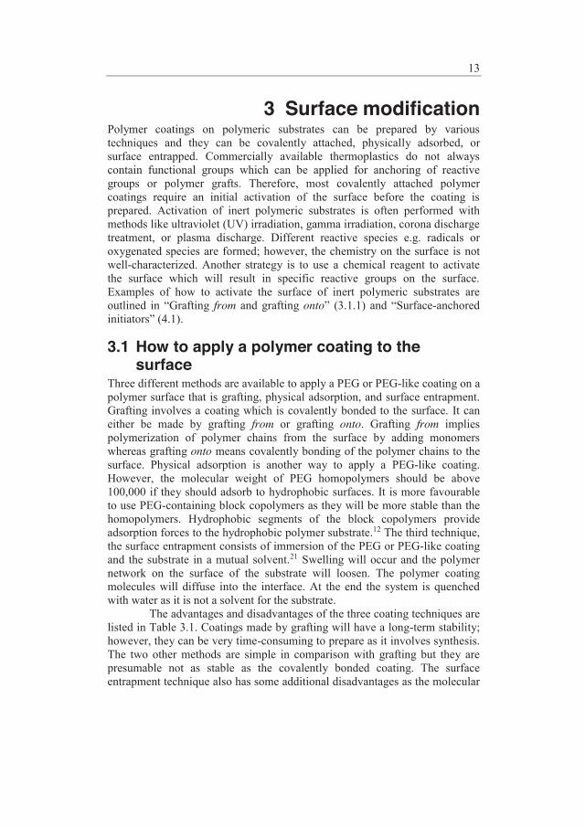
Three different methods are available to apply a PEG or PEG-like coating on a polymer surface that is grafting, physical adsorption, and surface entrapment. Grafting involves a coating which is covalently bonded to the surface. It can either be made by grafting from or grafting onto. Grafting from implies polymerization of polymer chains from the surface by adding monomers whereas grafting onto means covalently bonding of the polymer chains to the surface. Physical adsorption is another way to apply a PEG-like coating. However, the molecular weight of PEG homopolymers should be above 100,000 if they should adsorb to hydrophobic surfaces. It is more favourable to use PEG-containing block copolymers as they will be more stable than the homopolymers. Hydrophobic segments of the block copolymers provide adsorption forces to the hydrophobic polymer substrate.12 The third technique, the surface entrapment consists of immersion of the PEG or PEG-like coating and the substrate in a mutual solvent.21 Swelling will occur and the polymer network on the surface of the substrate will loosen. The polymer coating molecules will diffuse into the interface. At the end the system is quenched with water as it is not a solvent for the substrate.
The advantages and disadvantages of the three coating techniques are listed in Table 3.1. Coatings made by grafting will have a long-term stability; however, they can be very time-consuming to prepare as it involves synthesis. The two other methods are simple in comparison with grafting but they are presumable not as stable as the covalently bonded coating. The surface entrapment technique also has some additional disadvantages as the molecular

14
weight has influence on the solubility and it might be necessary to replace the solvent if the composition of the polymer coating is changed. Table 3.1 Pros and cons of the different techniques to apply a coating to a polymer surface.
Method Advantages Disadvantages Grafting Permanent; long-term
stability Time-consuming
Physical adsorption Simple method Not permanent
Surface entrapment Simple method Limitations in molecular weight if sufficient
entrapment should be obtained
The grafting technique was chosen as long-term stability was important for pharmaceutical packaging and delivery systems.
3.1.1 Grafting from or grafting onto When polymer chains are grafted onto a surface it requires reactive functional groups on the surface in order to attach the polymer chains. For polymeric substrates different chemical coupling reactions are employed to perform grafting onto. The chosen coupling reaction depends on the reactive groups on the surface which may have to be formed prior to the grafting onto. Figure 3.1 shows an example of chemical coupling of PEG to poly(ethylene terephthalate) (PET). PET films were reacted with 50% aqueous ethylene diamine to form amide bonds and cause chain cleavage.22 The resulting primary amines were used for coupling of cyanuric chloride activated PEG which was prepared as described by Shafer and Harris.23
NH
CH2
NH2
2
50% NH2CH2CH2NH2
40 ºC, 24 hrs
NN
N
Cl
Cl
O CH2CH2O CH3n
HN CH2 NH
2N
NN
Cl
O CH2CH2O CH3n
PET film
Benzene, 40 ºC, 36 hrs
Na2CO3
Figure 3.1 Coupling of cyanuric chloride activated PEG to PET films which have been treated with ethylene diamine.
Grafting onto has the advantage that the molecular weight of the polymer grafts can be determined before they are attached. However, steric hindrance of either the reactive groups on the surface or the polymer chains is expected to result in low grafting density.

15
Several graft polymerization techniques are available to prepare polymer chains which are grafted from the surface. Methods like plasma-induced or irradiation-induced graft polymerization have received a lot of attention in the biomedical research area. Treatment with plasma or irradiation has the advantage that inert materials can be activated using the same equipment. In Figure 3.2 poly(tetrafluoroethylene) PTFE films were hydrophilized by H2 plasma treatment as polar and oxygenated species e.g. hydroperoxide and peroxide were formed after exposure to air. The monomer, poly(ethylene glycol)methyl ether methacrylate (MPEGMA) was physically adsorbed by solution coating which was followed by argon plasma-induced graft polymerization. The resulting plasma-polymerized MPEGMA (pp-MPEGMA) was covalently attached to the PTFE surface.24
PTFE
H2 Plasma Air exposure
PTFE
OOH
O O
Hydroperoxide
Peroxide
Solution coating
1 wt% MPEGMA in CHCl3
Physically adsorbed MPEGMA
PTFE
OOH
O O Ar plasma-inducedgraft polymerization
PTFE
Covalent bonding with PTFE surface
pp-MPEGMA
Figure 3.2 Argon plasma-induced graft polymerization of MPEGMA from H2 plasma pretreated PTFE films.
A major drawback of plasma-induced or irradiation-induced graft polymerization is the large number of possible radical reactions which lead to an unknown chemical composition of the polymer coating. In order to overcome this problem as well as heating of the substrate pulsed plasma discharges have been introduced. Pulsed plasma polymerization is claimed to increase control of the coating chemistry which will result in less crosslinking.25 However, the challenge with free radicals trapped within the polymer network will always be present for coatings prepared by plasma or irradiation polymerization. The free radicals often cause degradation as various aging processes are initiated in open atmosphere.26 In order to obtain good control over the polymers grafted from the surface another procedure must be followed. The thickness of the polymeric layer can be controlled and block copolymer brushes can be obtained with cationic and anionic graft polymerization. However, these methods are not used very often as formation of surface bound initiators is troublesome and only a few monomers can be applied. In contrast, conventional free radical polymerization (CFRP) has fewer restrictions but block copolymer brushes cannot be made. A thick polymeric layer can be prepared by CFRP. Moreover, the grafting density can be controlled by carefully choosing the right polymerization conditions as well as the initiator.27 SI-ATRP combines the best from the two worlds; therefore, the versatility is great which makes it the most widespread method to graft from the surface. The chain length and the

16
grafting density have the potential of being controlled in SI-ATRP. Furthermore, SI-ATRP offers the possibility to obtain control of the polymer architecture and design linear or block shaped grafts. Several procedures are available to prepare initiating sites on polymeric/organic or metallic/inorganic substrates. Hydrophilic brushes can be prepared by SI-ATRP under mild polymerization conditions i.e. room temperature and in aqueous or methanolic media. The favourable polymerization conditions and the controllability, in particular make SI-ATRP of interest for this project.
17
4 Surface-Initiated Atom Transfer Radical Polymerization
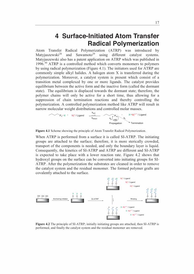
Atom Transfer Radical Polymerization (ATRP) was introduced by Matyjaszewski28 and Sawamoto29 using different catalyst systems. Matyjaszewski also has a patent application on ATRP which was published in 1996.30 ATRP is a controlled method which converts monomers to polymers by using radical polymerization (Figure 4.1). The initiators used for ATRP are commonly simple alkyl halides. A halogen atom X is transferred during the polymerization. Moreover, a catalyst system is present which consist of a transition metal complexed by one or more ligands. The catalyst provides equilibrium between the active form and the inactive form (called the dormant state). The equilibrium is displaced towards the dormant state; therefore, the polymer chains will only be active for a short time, thus allowing for a suppression of chain termination reactions and thereby controlling the polymerization. A controlled polymerization method like ATRP will result in narrow molecular weight distributions and controlled molar masses.
Pn X Mtx / Ligand
kact
kdeactPm
+MPropagation Termination
Mtx+1 / LigandX
kp kt
Figure 4.1 Scheme showing the principle of Atom Transfer Radical Polymerization.
When ATRP is performed from a surface it is called SI-ATRP. The initiating groups are attached to the surface; therefore, it is more sterically crowded, transport of the components is needed, and only the boundary layer is liquid. Consequently, the kinetics of SI-ATRP and ATRP are different and SI-ATRP is expected to take place with a lower reaction rate. Figure 4.2 shows that hydroxyl groups on the surface can be converted into initiating groups for SI-ATRP. After the polymerization the substrates are cleaned in order to remove the catalyst system and the residual monomer. The formed polymer grafts are covalently attached to the surface.
OH OH OHAnchoring initiator
O O OX X X
SI-ATRP
Mtx / Ligand
Mtx / Ligand
Mtx / Ligand
X X X
Mtx+1 / Ligand
Mtx+1 / Ligand
Mtx+1 / Ligand
X
X
XO O O
O O O
X X X
Rinsing
O O O
Figure 4.2 The principle of SI-ATRP; initially initiating groups are attached, then SI-ATRP is performed, and finally the catalyst system and the residual monomer are removed.
18
The anchoring of initiating groups is a very essential step and it depends on the surface of the substrate which does not always contain hydroxyl groups. Moreover, the initiating groups should be suitable for the particular monomer(s).
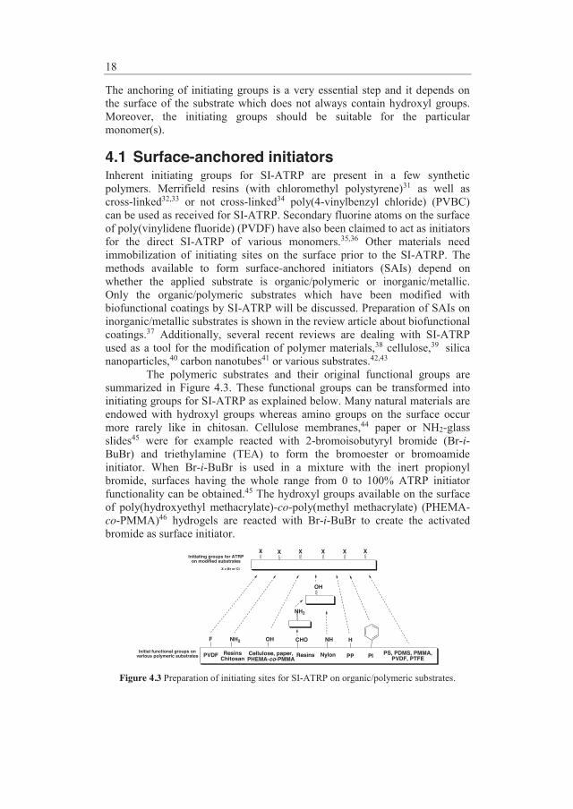
4.1 Surface-anchored initiators Inherent initiating groups for SI-ATRP are present in a few synthetic polymers. Merrifield resins (with chloromethyl polystyrene)31 as well as cross-linked32,33 or not cross-linked34 poly(4-vinylbenzyl chloride) (PVBC) can be used as received for SI-ATRP. Secondary fluorine atoms on the surface of poly(vinylidene fluoride) (PVDF) have also been claimed to act as initiators for the direct SI-ATRP of various monomers.35,36 Other materials need immobilization of initiating sites on the surface prior to the SI-ATRP. The methods available to form surface-anchored initiators (SAIs) depend on whether the applied substrate is organic/polymeric or inorganic/metallic. Only the organic/polymeric substrates which have been modified with biofunctional coatings by SI-ATRP will be discussed. Preparation of SAIs on inorganic/metallic substrates is shown in the review article about biofunctional coatings.37 Additionally, several recent reviews are dealing with SI-ATRP used as a tool for the modification of polymer materials,38 cellulose,39 silica nanoparticles,40 carbon nanotubes41 or various substrates.42,43 The polymeric substrates and their original functional groups are summarized in Figure 4.3. These functional groups can be transformed into initiating groups for SI-ATRP as explained below. Many natural materials are endowed with hydroxyl groups whereas amino groups on the surface occur more rarely like in chitosan. Cellulose membranes,44 paper or NH2-glass slides45 were for example reacted with 2-bromoisobutyryl bromide (Br-i-BuBr) and triethylamine (TEA) to form the bromoester or bromoamide initiator. When Br-i-BuBr is used in a mixture with the inert propionyl bromide, surfaces having the whole range from 0 to 100% ATRP initiator functionality can be obtained.45 The hydroxyl groups available on the surface of poly(hydroxyethyl methacrylate)-co-poly(methyl methacrylate) (PHEMA-co-PMMA)46 hydrogels are reacted with Br-i-BuBr to create the activated bromide as surface initiator.
NH2 OH
OH
X = Br or Cl
X X X X
NH
Initiating groups for ATRP on modified substrates
Cellulose, paper,PHEMA-co-PMMA
ResinsChitosan PI
H
NylonInitial functional groups on various polymeric substrates PP PS, PDMS, PMMA,
PVDF, PTFE
X
NH2
CHO
X
ResinsPVDF
F
Figure 4.3 Preparation of initiating sites for SI-ATRP on organic/polymeric substrates.

19
If the surface does not contain any hydroxyls, attempts are made to form hydroxyl groups: The commercial matrix for Electrostatic Ion Chromatography columns, Toyopearl® AF-650M contains surface aldehyde groups. The aldehydes on the surface undergo a sequence of reactions via amino, ring-opening of δ-gluconolactone into hydroxyls, and finally into chloropropionate initiating sites.47 Nylon membranes can be activated with formaldehyde.48 Initiating sites for SI-ATRP were also successfully attached to inert PP surfaces (CH2) by use of UV irradiation. Benzophenonyl 2-bromoisobutyrate (Figure 4.4) was synthesized from 4-hydroxybenzophenone and Br-i-BuBr, and was used as UV initiator. The formation of covalent C-C bonds was obtained by a procedure including spin coating of the UV initiator from a toluene solution onto PP surfaces, followed by UV treatment at λ = 365 nm.49
OO C
OC BrCH3
CH3
UV light365 nm
OO C
OC BrCH3
CH3
n
n
OHO C
OC BrCH3
CH3
Figure 4.4 Formation of SAIs on PP by UV irradiation of benzophenonyl 2-bromoisobutyrate.
Other specific reactions on polymers to form the SAIs also exist. Polyimide (PI) films have been anchored with benzyl chloride initiating sites for SI-ATRP by chloromethylation with paraformaldehyde/Me3SiCl in the presence of SnCl4.50 Ozone-pretreated PVDF has been thermally reacted with 2-(2-bromoisobutyryl)ethyl acrylate to prepare the SAIs.51,52 Chemical vapor deposition polymerization of [2.2]-paracyclophane-4-methyl 2-bromoisobutyrate53 (Figure 4.5) resulted in grafting (poly(dimethylsiloxane) (PDMS), PMMA, PTFE, and polystyrene (PS)) with initiating sites for SI-ATRP.
O
OBr
O
OBr
* *n
Chemical vapordepositionpolymerization
Figure 4.5 Initiating groups for SI-ATRP immobilized on various substrates by chemical vapor deposition polymerization of [2.2]-paracyclophane-4-methyl 2-bromoisobutyrate.
4.2 Lower amount of catalyst For medical devices and pharmaceutical packaging the presence of copper from the catalyst can have an undesirable impact on the drug and as a

20
consequence the health of the patient. Therefore, methods which will lower the amount of catalyst are to be preferred. In a broader perspective lowering the amount of catalyst will be beneficial both commercially and environmentally. In order to minimize the amount of copper from the catalyst Matyjaszewski and coworkers have introduced two new catalytical methods in which CuII in combination with a reducing agent is used instead of CuI. Activators generated by electron transfer (AGET) SI-ATRP was first introduced which uses >1000 ppm catalyst and nearly stoichometric amounts of reducing agent. The most recent development is activator regenerated by electron transfer (ARGET) SI-ATRP. In ARGET SI-ATRP the amount of copper catalyst is significant lower (tens of ppm values vs. monomer) and a large excess of reducing agent is applied.54,55 ARGET SI-ATRP differs from SI-ATRP in lower amount of catalyst and ligand and presence of reducing agent. Moreover, CuII is applied instead of CuI and continuously reduced by the reducing agent (Figure 4.6).
O O OX X X
CuI / LigandX
ka
kd
O O O
CuII / LigandX2m (m+n)
Reducing AgentOxidized Agent
+M kp
Figure 4.6 Principle of ARGET SI-ATRP; CuII is continuously reduced by the reducing agent to CuI.
Most studies with AGET and ARGET have been made in solution and not from surfaces; however, inspiration from these experiments can be used for SI-ATRP. AGET ATRP utilizes reducing agents which are unable to initiate new chains. The reducing agent reacts with the CuII complex and forms the CuI ATRP activator. Cu0, SnII 2-ethylhexanoate, ascorbic acid, and triethylamine have been reported as reducing agents for AGET ATRP. In ARGET ATRP the CuII is continuously reduced to CuI as a large enough excess of reducing agent to copper is applied. This makes it possible to lower the concentration of catalyst to initiator significantly. Good control was obtained with 50 ppm of copper for ARGET ATRP of acrylate and 10 ppm of copper for styrene polymerization. In addition to the reducing agents for AGET ATRP a number of organic derivatives of hydrazine, phenol, sugar, and ascorbic acid as well as inorganic species such as SnII and Cu0 can be used for ARGET ATRP.56 The AGET process is more sensitive to the added amount of reducing agent than ARGET. On one hand, a large excess of reducing agent in AGET will result in a large amount of CuI ATRP activator and as a consequence a fast uncontrolled process. On the other hand, an insufficient amount of reducing agent will not consume the air present and the polymerization will not occur. Removal of air from the system can especially be problematic for SI-ATRP from large substrates or large batches. Therefore, ARGET ATRP is more suitable for grafting from a surface than AGET.57

21
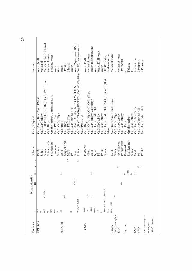
5 Biofunctional coatings Various monomers have been used for SI-ATRP to prepare polymer coatings which can be applied within the field of biotechnology. The term biofunctionality is used to emphasize that the polymer coating is not only of interest in biological applications but also that it has been tested within these applications. The monomers in Table 5.1 have been used for SI-ATRP and the resulting polymers have been investigated with respect to their biofunctionality. However, some of the polymers are not homopolymers. This is indicated by the letter “a” for diblock copolymers, “b” for copolymers, and “c” for comb copolymers. Six classifications for biofunctionality have been chosen in order to elucidate the applications of the monomers. The classifications include inhibition of non-specific fouling, immobilization of biomolecules, separation of proteins, adsorbents for proteins or cells, antibacterial activity, and encapsulation of drugs. Only examples within inhibition of fouling will be discussed here whereas the other biofunctionalities are included in the review article.37

22
Table
5.1
Surv
ey o
f po
lym
er g
rafts
with
diff
eren
t bi
ofun
ctio
nalit
ies
prep
ared
by
SI-A
TRP
and
repo
rted
in t
he l
itera
ture
bet
wee
n 19
97 a
nd 2
009.
B
iofu
nctio
nalit
y: I
nhib
ition
of
non-
spec
ific
foul
ing
(I),
Imm
obili
zatio
n of
bio
mol
ecul
es (
II),
Sepa
ratio
n of
pro
tein
s (I
II),
Ads
orbe
nts
for
prot
eins
or
cells
(IV
), A
ntib
acte
rial a
ctiv
ity (V
), an
d En
caps
ulat
ion
of d
rugs
(VI)
.
Mon
omer
B
iofu
nctio
nalit
y Su
bstra
te
Cat
alys
t:lig
and
Solv
ent
I II
II
I IV
V
V
I A
A
58b
44
Cel
lulo
se
Stai
nles
s ste
el
CuC
l:Me 4
Cyc
lam
G
rubb
s cat
alys
t W
ater
To
luen
e A
Am
59
,60
61
,62
Si
lica
Silic
on
CuC
l:Bip
y C
uCl:B
ipy,
CuC
l/CuC
l 2:B
ipy
DM
F D
MF,
wat
er
tBA
63
Gol
d C
uBr:P
MD
ETA
A
ceto
ne
tBA
EMA
58
,58b
Stai
nles
s ste
el
Gru
bbs c
atal
yst
Tolu
ene
tBM
A
64
Si
licon
C
uBr:P
MD
ETA
To
luen
e C
BM
A
65,6
6 65
G
old
CuB
r:Bip
y M
etha
nol:w
ater
D
EAEM
A
67
b G
old
CuB
r:SP
DM
F D
MA
EMA
68
68
45
49
32
52
40
67b
Gol
d G
lass
/filte
r pap
er
PP
PVB
C
PVD
F Ti
tani
um
CuB
r:Bip
y, C
uBr:S
P, C
uBr/C
uBr 2
:HM
TETA
C
uBr:B
ipy
CuC
l/CuC
l 2:H
MTE
TA
CuC
l/CuB
r 2:B
ipy
CuC
l/CuC
l 2:B
ipy
CuC
l/CuC
l 2:PM
DET
A69
Wat
er, D
MF,
ace
tone
o-
DC
B
Ace
tone
D
MF
Wat
er
DM
F69
DM
AA
m
47
To
yope
arl®
C
uCl/C
uCl 2/
Cu
pow
der:H
MTE
TA
Wat
er
GM
A
70a,
c 71
b 72
70
Fe3O
4 NP
Silic
on
CuB
r:PM
DET
A
CuC
l/CuC
l 2:B
ipy
Met
hano
l D
MF:
wat
er
GM
MA
71b
Fe3O
4 NP
CuB
r:PM
DET
A
Met
hano
l H
EMA
48
,48a
60,7
3
74,7
5 76
-79
75,8
0 81
82
73
Gla
ss
Gol
d N
ylon
Si
lica
Silic
on
Tita
nium
CuC
l/CuB
r 2:B
ipy
CuC
l/CuB
r 2:B
ipy
CuB
r/CuB
r 2:H
MTE
TA
CuB
r:Bip
y C
uCl/C
uCl 2
(Br 2
):Bip
y
CuC
l/CuC
l 2:PM
DET
A
Wat
er
Wat
er
Wat
er
Met
hano
l W
ater
W
ater
M
AA
S 83
83
Ti
tani
um
CuC
l/CuC
l 2:PM
DET
A
Wat
er
MA
IpG
lc
84
Si
licon
C
uBr:M
e 6TR
EN
Ver
atro
le
MEM
A
60
Si
licon
C
uCl/C
uCl 2:
Bip
y M
etha
nol
MM
A
85a
86
60
Dia
mon
d Fe
3O4 N
P Si
licon
CuC
l/CuC
l 2:PM
DET
A87
C
uCl:B
ipy
C
uCl/C
uCl 2:
Bip
y
Tolu
ene87
D
MF
THF
MPC
64
,88-
90
Si
licon
C
uBr:B
ipy
Met
hano
l, m
etha
nol:w
ater
M
PDSA
H
91
G
old
CuB
r/CuB
r 2:B
ipy
Met
hano
l:wat
er
MPE
GM
A
92
66,9
3-96
46
76,7
7,10
0
67
b
Gla
ss
Gol
d H
ydro
gels
CuB
r:Bip
y C
uBr:S
P, C
uCl/C
uBr 2
:Bip
y, C
uBr:B
ipy
CuB
r:Me 6
TREN
etc
.
Met
hano
l:wat
er
DM
F, w
ater
, met
hano
l:wat
er
Wat
er
23
Mon
omer
B
iofu
nctio
nalit
y Su
bstra
te
Cat
alys
t:lig
and
Solv
ent
I II
II
I IV
V
V
I M
PEG
MA
35
,36
97
93,9
7 92
58
,98
98,9
9 53
101,
102b
PV
DF
Silic
a Si
licon
Si
licon
oxi
de
Stai
nles
s ste
el
Tita
nium
V
ario
us
CuC
l/CuC
l 2:B
ipy,
CuC
l:DM
DP
CuC
l/CuC
l 2:B
ipy
CuC
l (B
r)/C
uCl 2
(Br 2
):Bip
y, C
uBr:P
MD
ETA
C
uBr:B
ipy
Gru
bbs c
atal
yst,
CuB
r:PM
DET
A
CuB
r:PM
DET
A
CuB
r/CuB
r 2:B
ipy
Wat
er, N
MP
Met
hano
l M
etha
nol,
wat
er, e
than
ol
Met
hano
l:wat
er
Tolu
ene,
wat
er
Wat
er
Wat
er
NIP
AA
m
103
34
70,1
04,1
05,1
05a,
b 106
107-
109
103
11
0 11
1
Gol
d M
agne
tic N
P M
CF
PS
Silic
a Si
licon
CuB
r:Bip
y C
uCl:B
ipy
CuB
r:PM
DET
A
CuC
l/CuC
l 2:M
e 6TR
EN
CuC
l/CuC
l 2:M
e 6TR
EN, C
uCl:M
e 6TR
EN
CuC
l (B
r)/C
uCl 2
(Br 2
):HM
TETA
, CuC
l/CuC
l 2:B
ipy,
C
uBr:P
MD
ETA
Wat
er
DM
SO
Etha
nol
Wat
er
Wat
er/2
-pro
pano
l, D
MF
DM
SO, m
etha
nol:w
ater
PEG
MA
85
a,11
2
113
114,
115
48,4
8a
116
51
105,
105a
,b,1
13,1
1
4,11
7
74,7
5 11
4 75
,101
b,11
4,11
7 11
5
Fe3O
4 NP
Gla
ss
Gol
d N
ylon
PI
PV
DF
Silic
on
CuC
l:Bip
y C
uBr/C
uBr 2
:Bip
y, C
uCl/C
uBr 2
:Bip
y C
uCl/C
uCl 2:
Bip
y, C
uBr:B
ipy
CuB
r/CuB
r 2:H
MTE
TA
CuC
l/CuC
l 2:B
ipy
CuC
l/CuC
l 2:B
ipy
CuB
r/CuB
r 2:H
MTE
TA, C
uCl (
Br)
/CuC
l 2 (B
r 2):
Bip
y
Wat
er, D
MF
Met
hano
l:wat
er
Wat
er, m
etha
nol:w
ater
W
ater
W
ater
, DM
F:w
ater
W
ater
D
MSO
, wat
er,
met
hano
l:wat
er
SBM
A
66,9
4,11
8,11
9
Gol
d C
uBr:B
ipy,
CuB
r/CuB
r 2:B
ipy
Met
hano
l:wat
er
Sodi
um a
cryl
ate
12
0
Si
licon
C
uBr/C
uBr 2
:Bip
y -
SPM
12
1
94
G
old/
silic
on
PS se
ed la
tex
C
uCl/C
uCl 2:
Bip
y C
uCl/C
uCl 2:
Bip
y M
etha
nol:w
ater
D
MF:
wat
er
Styr
ene
86
58
,58b
60
Dia
mon
d St
ainl
ess s
teel
Si
licon
CuB
r:Bip
y G
rubb
s cat
alys
t C
uCl/C
uCl 2:
Bip
y
- Tolu
ene
THF
2-V
P
122
Gol
d C
uBr/C
uCl 2:
Me 6
TREN
A
ceto
nitri
le
4-V
P
50
33
PI
PVB
C C
uCl/C
uCl 2:
Me 6
TREN
C
uBr/C
uBr 2
:Me 6
TREN
2-
Prop
anol
2-
Prop
anol
a D
ibloc
k Cop
olyme
r b C
opoly
mer
c Com
b cop
olyme
r

24
5.1 Inhibition of non-specific fouling Inhibition of non-specific fouling, non-fouling, antifouling, and resistance against biofouling are terms to describe surfaces which reduce both protein adsorption and cell adhesion. Interactions between the proteins or cells and the surface determine the tendency to undergo non-specific fouling. Hydrophobic and electrostatic interactions are considered to be the major driving forces for fouling; but the importance of these interactions depends on the protein structure and the surface properties. For instance, non-specific fouling depends on the surface wettability, specific chemical groups on the surface, surface charge, the balance between hydrophobic and hydrophilic groups, the mobility of the polymer brushes, and the structure of the adsorbed water.97
5.1.1 General examples of non-fouling polymeric grafts In Table 5.1, MPEGMA and poly(ethylene glycol) methacrylate (PEGMA) appear to be the most frequently used monomers to prepare non-fouling surfaces by SI-ATRP. PEG and its derivatives are finding more and more biological applications as PEG is known to prevent protein adsorption, to suppress platelet adhesion, and to reduce cell attachment and growth.117 Stainless steel and titanium are applied in medical devices due to their high strength, corrosion resistance, and biocompatibility. In order to prevent non-specific fouling on the metal, poly(MPEGMA) was grafted from the substrate.98 Many studies have been made to investigate the influence of graft density and chain length on the inhibition of non-specific fouling. One study with MPEGMA has looked at the influence of the MPEG chain length on short- and long-term fouling resistance of the polymer coatings. MPEGMA’s with side chains of 4, 9, and 23 EO units were included in the study. The short-term results for the three poly(MPEGMA)’s grafted from titanium showed reduced cell adhesion for three weeks compared to bare titanium. When the samples were kept for a longer time, they were completely covered with cells in 7, 10, and 11 weeks for poly(MPEGMA) with 4, 9, and 23 EO units respectively.99 Another study with grafted brushes of poly(MPEGMA) from poly(HEMA-co-MMA) hydrogels showed increasing cell repellency with increasing chain length compared to the untreated hydrogels.46 Singh et al. proved that the transition from mushroom to brush regime affects both the peptide adsorption and the cell adhesion. Peptide adsorption and cell adhesion occurred only in the mushroom regime for poly(PEGMA) grafted from gold. In the brush regime, when the graft density was high, there was negligible peptide adsorption and cell adhesion. Moreover, peptide adsorption in the mushroom regime promoted cell adhesion on the substrates, in contrast to the brush regime where cell adhesion was resisted even after preadsorption of an adhesion-promoting peptide.115 Many claim that the graft density is the most important parameter with respect to non-fouling properties of grafted polymers prepared by SI-ATRP and that the chain length or molecular weight
25
of the polymer grafts has a weaker influence.115 Feng et al.89 have verified this observation with poly(2-methacryloyloxyethyl phosphorylcholine) (poly(MPC)) grafted surfaces in some fibrinogen adsorption experiments in which the graft density was varied from 0.06 to 0.39 chains/nm2 and the chain length was from 5 to 200 MPC units. On the other hand, too high a graft density may cause detachment of the polymer brushes. Experiments with PEGMA polymerized from silicon or glass have shown that when a solution with only ATRP initiator modified trimethoxysilane was replaced by a mixture of 60 mol% ATRP initiator modified trimethoxysilane and 40 mol% inert trimethoxysilane, the stability of the poly(PEGMA) was enhanced from 1 to more than 7 days without any reduction in the non-fouling properties.113 Other monomers which have been shown to be capable of preventing non-specific fouling as homopolymers are acrylamide (AAm), 2-(tert-butylamino)ethyl methacrylate (tBAEMA), 2-carboxy-N,N-dimethyl-N-(2’-methacryloyloxyethyl)ethanaminium inner salt (CBMA), 2-(diethylamino)ethyl methacrylate (DMAEMA), HEMA, methacrylic acid sodium salt (MAAS), 3-O-methacryloyl-1,2:5,6-di-O-isopropylidene-D-glucofuranose (MAIpGlc), 2-methoxyethyl methacrylate (MEMA), MPC, (3-(methacryloylamino)propyl)-dimethyl(3-sulfopropyl) ammonium hydroxide (MPDSAH), N-isopropylacrylamide (NIPAAm), and sulfobetaine methacrylate (SBMA) (Figure 5.1A). The idea of incorporating phosphorylcholine moieties into the polymer coating originates from the fact that zwitterionic phospholipids, which are known from the outer membranes of cells, have been shown to be non-thrombogenic.88 The monomers CBMA,65,66 SBMA,66,94,118,119 and MPDSAH91 are zwitterionic like MPC. They were developed because the long-term stability of MPC is poor due to the tendency for MPC to undergo hydrolysis of the phosphoester group. Another reason for seeking other suitable monomers is the lack of stability of monomers containing PEG with hydroxyl end-groups, as they can be oxidized enzymatically to aldehydes and acids allowing proteins and cells to attach. Therefore, the utility of PEG and PEG derivates for applications which require long-term stability is reduced.94 In addition, hydroxyl groups in e.g. PEG, PEGMA, and HEMA may form hydrogen bonds with proteins, thus allowing them to attach. This will decrease the long-term durability of the polymer grafts. Cho et al.91 have published the first article on the non-specific fouling property of poly(MPDSAH)-coated surfaces. The poly(MPDSAH) brushes were able to suppress non-specific fouling to a level comparable to that of PEG-like coatings. The protein repellency was much better than that of phophorylcholine-based polymer grafts. Lysozyme, fibrinogen, bovine serum albumin (BSA), and ribonuclease A have been used as model proteins and the adsorption of proteins was < 0.6 ng/cm2.91 Homopolymer grafts of either poly(SBMA) or poly(AAm) were also able to inhibit bacterial adhesion in a flow chamber.59,94 In order to prevent fouling, the optimum thickness for poly(SBMA) grafts was 62 nm in 100% blood serum and plasma. Yang et al.119 also found that fouling decreased with increasing ionic strength. A study

26
which compared poly(CBMA), poly(MPEGMA), and poly(SBMA) grafts with self-assembled monolayers on gold showed higher resistance to fouling from 100% plasma for the polymer grafts. Poly(CBMA) was the most interesting polymer for blood-contacting applications, as it had the overall lowest level of protein adsorption and an anticoagulant activity was observed.66 The monomer MAIpGlc can also be used to prepare blood-compatible polymer brushes. After SI-ATRP of MAIpGlc, deprotection and then sulfonation was performed. The resulting polymer brushes contained sulfonated sugar repeating units and they were claimed to mimic heparin. Heparin can participate in a catalytic cycle of coagulation factor inactivation. Moreover, it is known to reduce platelet adhesion and protein adsorption.84
OO
MPEGMA
DMAEMAtBAEMA
HN
OO
N O
OCBMA
OO
N
OO
HEMA
OO
OH
OO
O
MEMA
OO
N
S O
SBMAO
O
OO
OO
O
OO
MAIpGlc
O n
PEGMA
OO
OHn
H2NO
AAm
HNO
NIPAAm
OO
O PO
OO
N
MPC
HNO
N
S OO
OMPDSAH
OO
Na
MAAS
A)
B)
OO
MMA
HOO
AA
OO
O
GMA Figure 5.1 A) Polymer grafts on surfaces made from the monomers inhibit non-specific fouling; B) The monomers result in antifouling coatings when incorporated in copolymer structures. HEMA48 and MEMA60 are similar to PEGMA and MPEGMA respectively, but they have a side chain containing only one EO unit. Poly(HEMA) showed the same correlation between graft density and cell/protein rejection as the poly(PEGMA) (vide supra).73 Cationic poly(DMAEMA) brushes distinguish themselves by rejecting net positively charged lysozyme proteins and they have a high binding capacity for net negatively charged BSA.68 Poly(NIPAAm) has been used to prepare thermoresponsive surfaces due to its lower critical solution temperature

27
(LCST) at about 32 ºC in aqueous solution. Below the LCST, poly(NIPAAm) is hydrophilic in water and cells can detach from the surface. If the temperature is increased to above the LCST, hydrogen bonding between the isopropylamide moiety and water molecules is lost and the surface becomes hydrophobic. Various cells will therefore adhere, spread and proliferate at 37 ºC on poly(NIPAAm) surfaces.70,103,105 Li et al.104 have also shown that, at 37 ºC and with a poly(NIPAAm) thickness of ≤ 45 nm, cells could adhere and proliferate. Above 45 nm, the cells could not adhere, whereas between 20 and 45 nm they could be attached or detached by switching the temperature.104 Mizutani et al.34 also demonstrated that the thicker the poly(NIPAAm) layer was the smaller was the amount of proteins adsorbed and cells adhered. For thin poly(NIPAAm) layers, the temperature had an impact, as cells detached at lower temperature (20 ºC).34 Copolymer brushes with PEGMA105 and comb copolymer brushes with glycidyl methacrylate (GMA)70 (Figure 5.1B) have resulted in more rapid cell detachment during the temperature transition and cell recovery at 20 ºC, without influencing either cell adhesion or growth. Ignatova et al.58 have studied fouling on polymer coatings prepared from tBAEMA and mixtures of this monomer with acrylic acid (AA), MPEGMA, and styrene. Copolymer brushes of tBAEMA and AA or MPEGMA were more effective in avoiding protein adsorption than poly(tBAEMA) copolymers with styrene, and PS, whereas both homopolymer brushes of tBAEMA and copolymer brushes with MPEGMA and AA were more effective in decreasing bacterial adhesion than PS and copolymer brushes of tBAEMA and styrene.58
5.1.2 Non-fouling grafts for separation of proteins SI-ATRP is a suitable method to modify column material for various chromatographic techniques in order to prevent protein adsorption to the packing material which is known to undermine purification, recovery, and analysis.62 The polymer coating must be uniform to avoid blocking of the pores; moreover, it should be covalently attached to the surface, as polymers formed in solution inside the pores will block the pores. SI-ATRP also offers the ability to control the thickness of the polymer coating as opposed to conventional radical polymerization.62 If the purpose is to separate proteins by chromatography, e.g. Size Exclusion Chromatography (SEC), Capillary Electrophoresis or High Performance Liquid Chromatography (HPLC), the column material could be modified with polymer brushes made from the monomers AAm,62,66 N,N-dimethylacrylamide (DMAAm),47 HEMA,82 NIPAAm,108 or SPM121 (Figure 5.2).

28
HEMA
OO
OH
H2NO
AAm
HNO
NIPAAm
NO
DMAAm
OO
SO
OOK
SPM Figure 5.2 SI-ATRP of the monomers on column materials improves separation of proteins.
The grafting density and the chain length of the polymer brushes will influence the separation of proteins. With a high grafting density of poly(DMAAm), i.e. in the brush regime, separation of lower molecular weight proteins is possible. In the mushroom regime, i.e. at low grafting density, the proteins which can be separated include the high molecular weight proteins (> 100 kDa).47 When the molecular weight of the poly(DMAAm) brushes is high, the separation of proteins with a large difference in molecular weight will be significantly better than with lower molecular weight brushes.47 Studies with poly(NIPAAm) brushes have shown that separation of hydrophilic substances like proteins or peptides takes place only above the LCST transition. Therefore, proteins are separated through hydrophobic interactions whereas lower molecular weight substances are separated in the SEC mode. Thus, longer retention times are observed for hydrophobic steroids due to their longer permeation path through the matrix. For this reason, not only temperature but also the grafting density of poly(NIPAAm) is crucial for the elution of steroids due to the interactions between analytes and brushes and the dehydration of the poly(NIPAAm) brushes on the densely packed surface.107-109
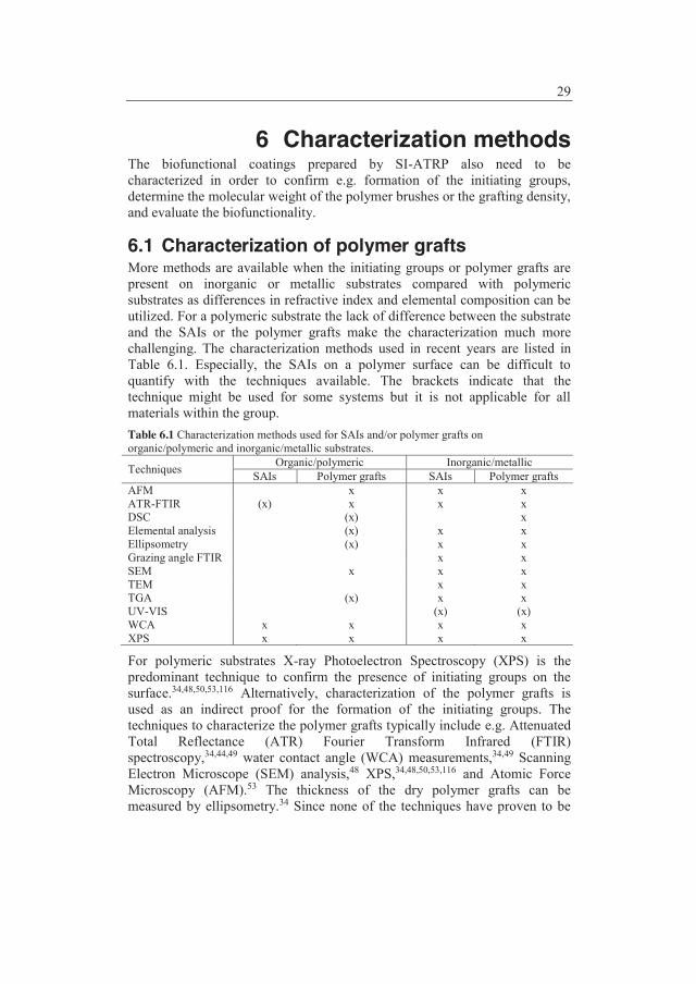
29
6 Characterization methods The biofunctional coatings prepared by SI-ATRP also need to be characterized in order to confirm e.g. formation of the initiating groups, determine the molecular weight of the polymer brushes or the grafting density, and evaluate the biofunctionality.
6.1 Characterization of polymer grafts More methods are available when the initiating groups or polymer grafts are present on inorganic or metallic substrates compared with polymeric substrates as differences in refractive index and elemental composition can be utilized. For a polymeric substrate the lack of difference between the substrate and the SAIs or the polymer grafts make the characterization much more challenging. The characterization methods used in recent years are listed in Table 6.1. Especially, the SAIs on a polymer surface can be difficult to quantify with the techniques available. The brackets indicate that the technique might be used for some systems but it is not applicable for all materials within the group. Table 6.1 Characterization methods used for SAIs and/or polymer grafts on organic/polymeric and inorganic/metallic substrates.
Techniques Organic/polymeric Inorganic/metallic SAIs Polymer grafts SAIs Polymer grafts
AFM x x x ATR-FTIR (x) x x x DSC (x) x Elemental analysis (x) x x Ellipsometry (x) x x Grazing angle FTIR x x SEM x x x TEM x x TGA (x) x x UV-VIS (x) (x) WCA x x x x XPS x x x x
For polymeric substrates X-ray Photoelectron Spectroscopy (XPS) is the predominant technique to confirm the presence of initiating groups on the surface.34,48,50,53,116 Alternatively, characterization of the polymer grafts is used as an indirect proof for the formation of the initiating groups. The techniques to characterize the polymer grafts typically include e.g. Attenuated Total Reflectance (ATR) Fourier Transform Infrared (FTIR) spectroscopy,34,44,49 water contact angle (WCA) measurements,34,49 Scanning Electron Microscope (SEM) analysis,48 XPS,34,48,50,53,116 and Atomic Force Microscopy (AFM).53 The thickness of the dry polymer grafts can be measured by ellipsometry.34 Since none of the techniques have proven to be

30
very useful for quantification of the initiating sites it is also not possible to obtain information about the grafting density.
The list of characterization methods for inorganic or metallic substrates is more comprehensive as the differences between the organic layer and the substrate gives additional possibilities. As a consequence, more results with inorganic or metallic substrates have been published. The formation of initiating groups on inorganic or metallic substrates is often confirmed by FTIR46,110,111 or FTIR equipped with a grazing angle accessories91,100,114,115 as well as water contact angle measurements,64,91,100,115 and XPS.46,53,59,64,83-85,100-
102,114 Other methods such as ellipsometry,100 elemental analysis,108,109 and AFM64,102 are also applied to evaluate the presence of the initiating groups. Thermal Gravimetric Analysis (TGA),110 Transmission Electron Microscopy (TEM) images,77,110 and UV-visible spectroscopy77 are methods that have been used more rarely; however, they can be very useful in some applications. The characterization methods for polymer grafts from inorganic or metallic substrates include many of the same techniques as for the initiating groups e.g. FTIR,59,60,85,94,97,110,111 FTIR with grazing angle,53,73,91,100,114 WCA, 46,60,64,83,91,100,104,111,113,115,120 and XPS.53,59,81,83-85,94,101,102,104,114 In addition to the confirmation of the polymer coating prepared by SI-ATRP techniques like XPS,75,91 ellipsometry,44,53,59,64,78,79,94,104,113,114,120 and AFM119,120 can also be applied to measure the thickness of the polymer grafts. Ellipsometry has even been used to determine the grafting density of polymer brushes.115 Other interesting characteristics for the polymer grafts can also be evaluated e.g. surface topography by AFM,59,64,101,102,104,120 weight loss by TGA,85,97,110 temperature transition by Differential Scanning Calorimetry,110 or calculation of the amount of various chemical elements by elemental analysis.108,109 SEM46,102,108 or TEM77,85,110 images can give a visual confirmation of the polymers grafted from the substrate.
The molecular weight and the polydispersity index (PDI) of the polymers grafted from a substrate can be determined by two different approaches. The polymer chains can be cleaved from the substrate by etching with HCl123 or HF60,108,109,111 as well as by hydrolysis with NaOH.47 This approach has been reported mainly for inorganic or metallic substrates whereas the other approach with a free or “sacrificial” initiator also has been used for polymeric substrates.49,59,64,68,82 When adding a free or “sacrificial” initiator e.g. ethyl 2-bromoisobutyrate to the reaction mixture the amount of initiating groups on the substrate is neglected. Therefore, the molecular weight of the resulting bulk and grafted polymer is claimed only to be a function of the “sacrificial” initiator-to-monomer ratio.124,125 Others even insist that addition of a comparatively large amount of “sacrificial” initiator to the polymerization is required to maintain adequate control of the SI-ATRP process.126,127 Independent of the approach chosen the molecular weight and the PDI is determined by SEC. Moreover, the results from SEC analysis enable calculation of the grafting density.

31
6.2 Methods to demonstrate inhibition of fouling Techniques to determine protein adsorption and cell attachment are of great interest to many researchers. The most common characterization methods to investigate non-spedific fouling are Surface Plasmon Resonance (SPR)66,68,78,82,91,100,114,115,118,119 and Quartz Crystal Microbalance (QCM)114 which both have a detection limit of 1 μg/cm2. SPR and QCM are complementary methods to investigate binding characteristics of proteins or cells.114 Both techniques are using specific substrates. For SPR substrates like gold, silver and copper can be applied. The surfaces can be modified with polymer grafts; however, the SPR biosensor has some limitations in the thickness of the polymeric layer. The polymer coating should be able to allow the light to go through as the incoming light induces formation of surface plasmon waves at the metal surface. The plasmons are sensitive to the refractive index at the boundary layer. When non-specific adsorption occurs the refractive index at the surface changes. The SPR detector monitors the changes in refractive index which allows us to follow adsorption in real time and measure changes in thickness.128 The measurements with SPR may differ from the scope of the application as they are performed in a flow cell. The quartz crystal used for QCM has a layer of gold and electrodes plated on it. Moreover, the crystal is piezoelectric and mechanical deformation of the material is induced by an external electrical field.129 A resonant oscillation should be obtained for the crystal close to the fundamental frequency of the crystal, and when non-specific adsorption takes place the frequency changes. The change in resonant frequency is measured and the mass of the adsorbed layer can be calculated. The application of the material should be considered before the QCM measurements are carried out as the possibilities are many among the commercially available systems. The measurements can be made in either static or flow sample cells under vacuum, in gas phase or in liquid environment.130
Fluorescence microscopy is a visual way to demonstrate non-specific adsorption of proteins46,102,120 and cells or bacteria81-83,113,118 and it relies on the use of fluorophores which will provide an image contrast. Synonyms for fluorophores are dyes, stains or labels. The fluorophore is either naturally present in the sample or added prior to the analysis. If the sample fluoresces by itself after absorption of light the process is called autofluorescence. Traditionally, wide-field fluorescence microscopes are applied to visualize non-specific fouling. However, the confocal fluorescence microscope will offer better resolution and the possibility of true three-dimensional optical resolution. A pinhole in front of the detector is used in a confocal fluorescence microscope to block the light from the out-of-focus planes. Fluorescence from the fluorophores in the out-of-focus planes causes blurring of the image in wide-field microscopy.131

32

33
7 Model system Poly(ether ether ketone) (PEEK) has been applied as a model substrate for SI-ATRP. The substrates of interest were e.g. PP, polycarbonate, and cyclic olefin copolymers which are quite inert polymer materials; therefore, anchoring of initiating sites could be challenging. The aim of the experiments with the model system was to demonstrate that SI-ATRP of selected monomers could be performed and would result in hydrophilization of the substrate. The example below is with PEGMA grafted from PEEK by SI-ATRP. During the last 30 years PEEK has been known for its biological applications which require surface modification to change the hydrophobicity of the material. Techniques like plasma treatment or deposition (mainly plasma spraying of Ti and/or thermal plasma coating of hydroxyapatite) as well as wet chemistry132-136 are commonly used.137 The most powerful method is coating of the hydrophobic PEEK with a hydrophilic polymer. In that way, an entire new surface layer is added to the substrate. The experimental details for grafting of PEGMA from PEEK are shown in Appendix B.
7.1 Results and discussion The surface of PEEK was functionalized by covalently bonding of hydrophilic polymer grafts of PEGMA from initiator-modified PEEK using SI-ATRP. Surface reduction of PEEK to form hydroxyl groups134 (Figure 7.1) was performed prior to the attachment of 2-bromoisobutyrate initiating groups (Figure 7.2). The reduction of the ketone groups with sodium borohydride in DMSO at 120 ºC did not dissolve the films which makes the method very useful for implantable devices e.g. spinal implants, orthopedic bearing and hip stem material.137
OO O **
n OHO O **
n
NaBH4DMSO
3 hours at 120 ºC
Poly (ether ether ketone), PEEK PEEK-OH
Figure 7.1 Activation of the PEEK surface with sodium borohydride. SI-ATRP of the monomer PEGMA was performed in aqueous media in the presence of the catalyst system 2,2’-bipyridine and copper chloride. The same ATRP conditions have been used with the initiator, ethyl 2-bromoisobutyrate and without substrates. Moreover, water has been replaced with methanol and the homopolymerizations only resulted in a gel when performed in water but not in methanol. The gel formation strongly indicates that polymer chains have reacted with each other and formed crosslinks. Therefore, the poly(PEGMA) grafts were presumably also crosslinked. Further characterization has only been performed on grafts prepared by SI-ATRP of PEGMA in water.
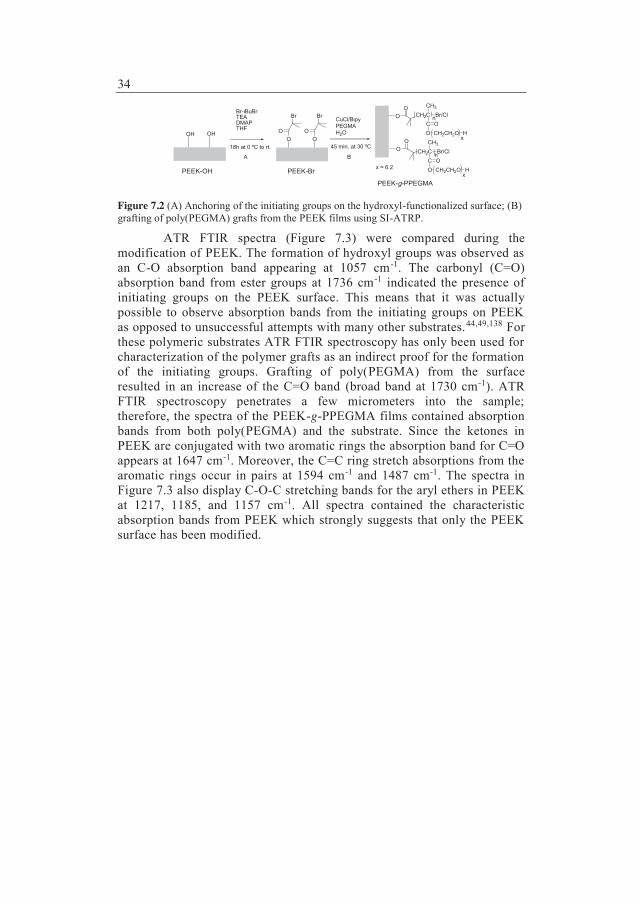
34
OH OH
Br-iBuBrTEADMAPTHF
18h at 0 ºC to rt.O
Br
OO
Br
O
CuCl/BipyPEGMAH2O
45 min. at 30 ºC OO
OO
CH2CCH3
C OO
Br/Cl
CH2CH2O H
CH2CCH3
C OO
Br/Cl
CH2CH2O H
x
x
n
n
x = 6.2PEEK-OH PEEK-Br
PEEK-g-PPEGMA
A B
Figure 7.2 (A) Anchoring of the initiating groups on the hydroxyl-functionalized surface; (B) grafting of poly(PEGMA) grafts from the PEEK films using SI-ATRP.
ATR FTIR spectra (Figure 7.3) were compared during the modification of PEEK. The formation of hydroxyl groups was observed as an C-O absorption band appearing at 1057 cm-1. The carbonyl (C=O) absorption band from ester groups at 1736 cm-1 indicated the presence of initiating groups on the PEEK surface. This means that it was actually possible to observe absorption bands from the initiating groups on PEEK as opposed to unsuccessful attempts with many other substrates.44,49,138 For these polymeric substrates ATR FTIR spectroscopy has only been used for characterization of the polymer grafts as an indirect proof for the formation of the initiating groups. Grafting of poly(PEGMA) from the surface resulted in an increase of the C=O band (broad band at 1730 cm-1). ATR FTIR spectroscopy penetrates a few micrometers into the sample; therefore, the spectra of the PEEK-g-PPEGMA films contained absorption bands from both poly(PEGMA) and the substrate. Since the ketones in PEEK are conjugated with two aromatic rings the absorption band for C=O appears at 1647 cm-1. Moreover, the C=C ring stretch absorptions from the aromatic rings occur in pairs at 1594 cm-1 and 1487 cm-1. The spectra in Figure 7.3 also display C-O-C stretching bands for the aryl ethers in PEEK at 1217, 1185, and 1157 cm-1. All spectra contained the characteristic absorption bands from PEEK which strongly suggests that only the PEEK surface has been modified.

35
Figure 7.3 FT-IR spectra of the unmodified and modified PEEK films. The advancing and receding WCAs decreased as the films were modified, reflecting the high hydrophilicity of the hydroxyl groups and poly(PEGMA) (Table 7.1). For the unmodified PEEK and the PEEK with poly(PEGMA) grafts the WCAs of the smooth and the rough side were compared. As expected it was observed that the contact angle hysteresis was larger for the rough side due to the enhanced surface roughness and possibly also surface heterogeneity. The rough side had uniform stripes
1307
1412
1279
0
0.005
0.01
0.015
0.02
0.025
1650170017501800
Wavenumber, cm-1
Ab
sorb
an
ce 1736
1730
0
0.02
0.04
0.06
0.08
0.1
0.12
0.14
101510651115
Wavenumber, cm-1
Ab
sorb
an
ce
1062 1057
673
834
926
1010
1098
1157
1217
1487
1594
1647
0
0.05
0.1
0.15
0.2
0.25
500100015002000250030003500
Wavenumber, cm-1
Ab
sorb
an
ce
PEEK unmodifiedPEEK-OHPEEK-BrPEEK-g-PPEGMA
1185
766
623
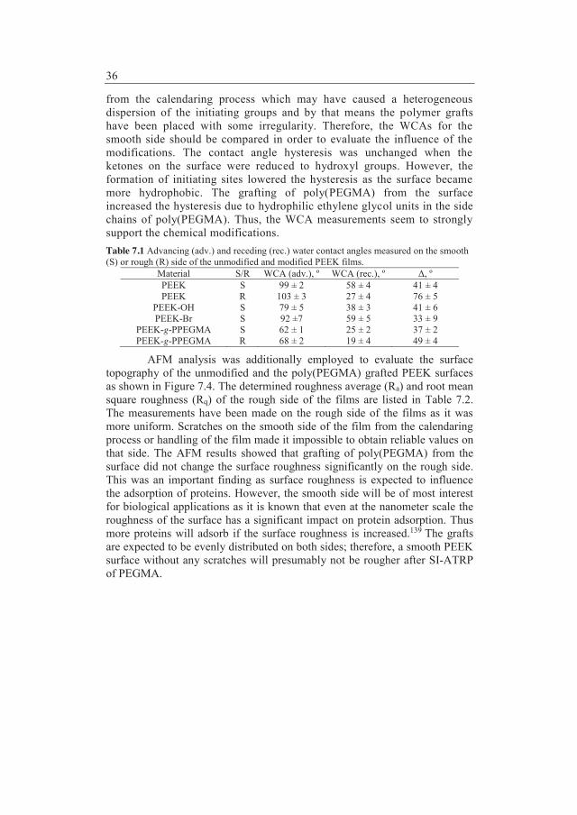
36
from the calendaring process which may have caused a heterogeneous dispersion of the initiating groups and by that means the polymer grafts have been placed with some irregularity. Therefore, the WCAs for the smooth side should be compared in order to evaluate the influence of the modifications. The contact angle hysteresis was unchanged when the ketones on the surface were reduced to hydroxyl groups. However, the formation of initiating sites lowered the hysteresis as the surface became more hydrophobic. The grafting of poly(PEGMA) from the surface increased the hysteresis due to hydrophilic ethylene glycol units in the side chains of poly(PEGMA). Thus, the WCA measurements seem to strongly support the chemical modifications.
Table 7.1 Advancing (adv.) and receding (rec.) water contact angles measured on the smooth (S) or rough (R) side of the unmodified and modified PEEK films.
Material S/R WCA (adv.), º WCA (rec.), º Δ, º PEEK S 99 ± 2 58 ± 4 41 ± 4 PEEK R 103 ± 3 27 ± 4 76 ± 5
PEEK-OH S 79 ± 5 38 ± 3 41 ± 6 PEEK-Br S 92 ±7 59 ± 5 33 ± 9
PEEK-g-PPEGMA S 62 ± 1 25 ± 2 37 ± 2 PEEK-g-PPEGMA R 68 ± 2 19 ± 4 49 ± 4
AFM analysis was additionally employed to evaluate the surface topography of the unmodified and the poly(PEGMA) grafted PEEK surfaces as shown in Figure 7.4. The determined roughness average (Ra) and root mean square roughness (Rq) of the rough side of the films are listed in Table 7.2. The measurements have been made on the rough side of the films as it was more uniform. Scratches on the smooth side of the film from the calendaring process or handling of the film made it impossible to obtain reliable values on that side. The AFM results showed that grafting of poly(PEGMA) from the surface did not change the surface roughness significantly on the rough side. This was an important finding as surface roughness is expected to influence the adsorption of proteins. However, the smooth side will be of most interest for biological applications as it is known that even at the nanometer scale the roughness of the surface has a significant impact on protein adsorption. Thus more proteins will adsorb if the surface roughness is increased.139 The grafts are expected to be evenly distributed on both sides; therefore, a smooth PEEK surface without any scratches will presumably not be rougher after SI-ATRP of PEGMA.
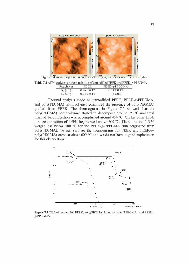
37
Figure 7.4 AFM images of unmodified PEEK (left) and PEEK-g-PPEGMA (right).
Table 7.2 AFM analyses on the rough side of unmodified PEEK and PEEK-g-PPEGMA. Roughness PEEK PEEK-g-PPEGMA
Ra (μm) 0.76 ± 0.12 0.79 ± 0.18 Rq (μm) 0.94 ± 0.14 1.0 ± 0.2
Thermal analysis made on unmodified PEEK, PEEK-g-PPEGMA, and poly(PEGMA) homopolymer confirmed the presence of poly(PEGMA) grafted from PEEK. The thermograms in Figure 7.5 showed that the poly(PEGMA) homopolymer started to decompose around 75 °C and total thermal decomposition was accomplished around 450 ºC. On the other hand, the decomposition of PEEK begins well above 500 °C. Therefore, the 2-3 % weight loss below 500 ºC for the PEEK-g-PPEGMA film originated from poly(PEGMA). To our surprise the thermograms for PEEK and PEEK-g-poly(PEGMA) cross at about 600 ºC and we do not have a good explanation for this observation.
Figure 7.5 TGA of unmodified PEEK, poly(PEGMA) homopolymer (PPEGMA), and PEEK-g-PPEGMA.

38
XPS has been used to investigate the PEEK surface functionalization. Scan survey spectra were used to identify and quantify the elements in the modified PEEK samples. The results are collected in Table 7.3 where also the C/O ratio was calculated in order to follow the modification steps. When poly(PEGMA) was grafted from the surface the C/O ratio was lowered as a consequence of the increased oxygen content in the grafts. Table 7.3 XPS analyses of the PEEK samples.
Element (%) PEEK PEEK-OH PEEK-Br PEEK-g-
PPEGMA Calc.
poly(PEGMA) C 93.7 84.3 82.9 70.5 64 O 6.3 15.7 15.6 29.5 32 Br 1.6 4
C/O ratio 15.0 5.4 5.3 2.4 2
Chemical composition information was obtained from high resolution scans (Table 7.4). The ketones on the surface of the PEEK films were reduced to hydroxyl groups. Therefore, C=O was not detected for PEEK-OH. This was previously also observed by Noiset et al.134 When the initiating sites were introduced O=C was found due to the ester groups from Br-iBuBr. For the poly(PEGMA) grafts the content of C-O increased as the PEG side chains contains ethers. XPS analysis on PEEK-g-PPEGMA confirmed that the PEEK surface was modified with poly(PEGMA) as the measured chemical composition only resembles that of the poly(PEGMA) brushes. Taken the penetration of the X-rays in XPS into account this implies that the poly(PEGMA) layer is more than 10 nm. Table 7.4 Chemical composition information from XPS.
Binding Energy, eV Attribution PEEK, % PEEK-OH, % PEEK-Br, % PEEK-g-
PPEGMA, % 284.3-284.9 C-C (C1s) 90.3 77.4 72.0 42.5 285.3-286.5 C-O (C1s) 8.0 17.0 20.7 50.4 288.3-289.0 C=O (C1s) * * 7.0
<283.9 or >287.7 Residual 1.7 5.6 3.0 530.8-531.9 O=C (O1s) 82.3 50.8 3.5
532.5 O-H (O1s) * 77.4 532.6-533.5 O-C (O1s) 11.4 97.9 49.2 14.4
<530.4 or >534.1 Residual 6.4 2.1 4.7
* the program was unable to resolve the peaks
The hydrophilic poly(PEGMA) grafts have different applications within the biomedical field as they can be used to avoid non-specific fouling (Figure 7.6). When PEEK-g-PPEGMA is pulled out of a protein solution, proteins should not be adsorbed to the surface.

39
PEEK-g-PPEGMA
Immersion inprotein solution Pulled out of
the solution
Figure 7.6 The crosslinked poly(PEGMA) grafts on PEEK are expected to repel proteins when the plates are removed from a protein solution.
Confocal fluorescence microscopy has been applied to investigate whether proteins labelled with a fluorophore would adsorb to the poly(PEGMA) surface. Unfortunately, PEEK exhibits autofluorescence at all the employed wavelengths (405, 445, 488, 555, and 639 nm) which makes it impossible to obtain good images of unmodified and modified PEEK exposed to fluorescenced proteins. However, poly(PEGMA) grafted from both polymeric and metallic substrates using SI-ATRP has previously been reported as a non-fouling material.48,51,105,112-117
7.2 Conclusions Polymer brushes of poly(PEGMA) were grafted from PEEK films by use of Surface-Initiated ATRP. The water contact angles were lower for the modified PEEK films; thus hydrophilization of PEEK was achieved. AFM analyses showed that the surface modification did not change the surface roughness. The C/O ratio as well as data from the high resolution XPS confirmed the grafting from the PEEK films. The hydrophilicity of the material, PEEK-g-poly(PEGMA) makes it applicable for inhibition of non-specific fouling.

40
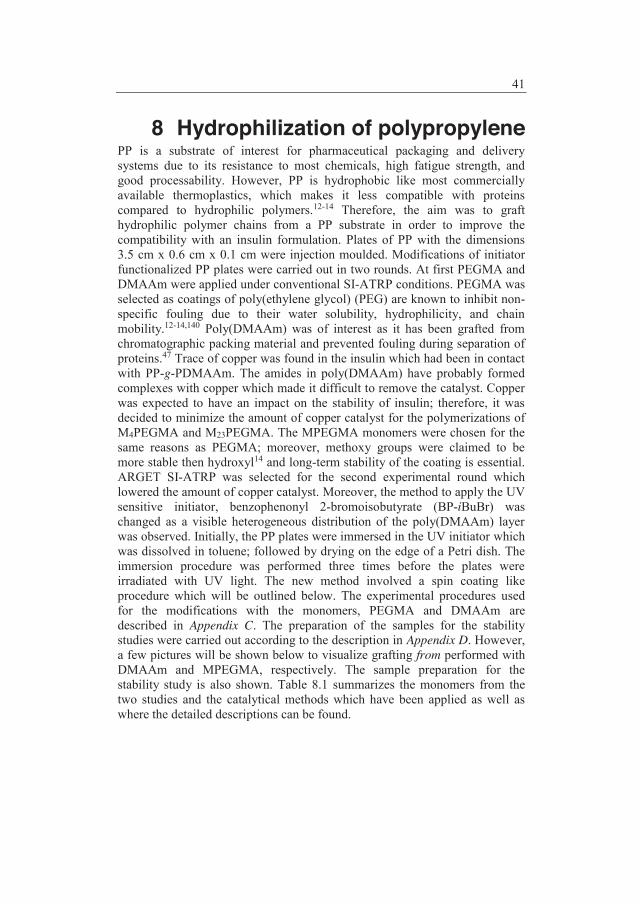
41
8 Hydrophilization of polypropylene PP is a substrate of interest for pharmaceutical packaging and delivery systems due to its resistance to most chemicals, high fatigue strength, and good processability. However, PP is hydrophobic like most commercially available thermoplastics, which makes it less compatible with proteins compared to hydrophilic polymers.12-14 Therefore, the aim was to graft hydrophilic polymer chains from a PP substrate in order to improve the compatibility with an insulin formulation. Plates of PP with the dimensions 3.5 cm x 0.6 cm x 0.1 cm were injection moulded. Modifications of initiator functionalized PP plates were carried out in two rounds. At first PEGMA and DMAAm were applied under conventional SI-ATRP conditions. PEGMA was selected as coatings of poly(ethylene glycol) (PEG) are known to inhibit non-specific fouling due to their water solubility, hydrophilicity, and chain mobility.12-14,140 Poly(DMAAm) was of interest as it has been grafted from chromatographic packing material and prevented fouling during separation of proteins.47 Trace of copper was found in the insulin which had been in contact with PP-g-PDMAAm. The amides in poly(DMAAm) have probably formed complexes with copper which made it difficult to remove the catalyst. Copper was expected to have an impact on the stability of insulin; therefore, it was decided to minimize the amount of copper catalyst for the polymerizations of M4PEGMA and M23PEGMA. The MPEGMA monomers were chosen for the same reasons as PEGMA; moreover, methoxy groups were claimed to be more stable then hydroxyl14 and long-term stability of the coating is essential. ARGET SI-ATRP was selected for the second experimental round which lowered the amount of copper catalyst. Moreover, the method to apply the UV sensitive initiator, benzophenonyl 2-bromoisobutyrate (BP-iBuBr) was changed as a visible heterogeneous distribution of the poly(DMAAm) layer was observed. Initially, the PP plates were immersed in the UV initiator which was dissolved in toluene; followed by drying on the edge of a Petri dish. The immersion procedure was performed three times before the plates were irradiated with UV light. The new method involved a spin coating like procedure which will be outlined below. The experimental procedures used for the modifications with the monomers, PEGMA and DMAAm are described in Appendix C. The preparation of the samples for the stability studies were carried out according to the description in Appendix D. However, a few pictures will be shown below to visualize grafting from performed with DMAAm and MPEGMA, respectively. The sample preparation for the stability study is also shown. Table 8.1 summarizes the monomers from the two studies and the catalytical methods which have been applied as well as where the detailed descriptions can be found.
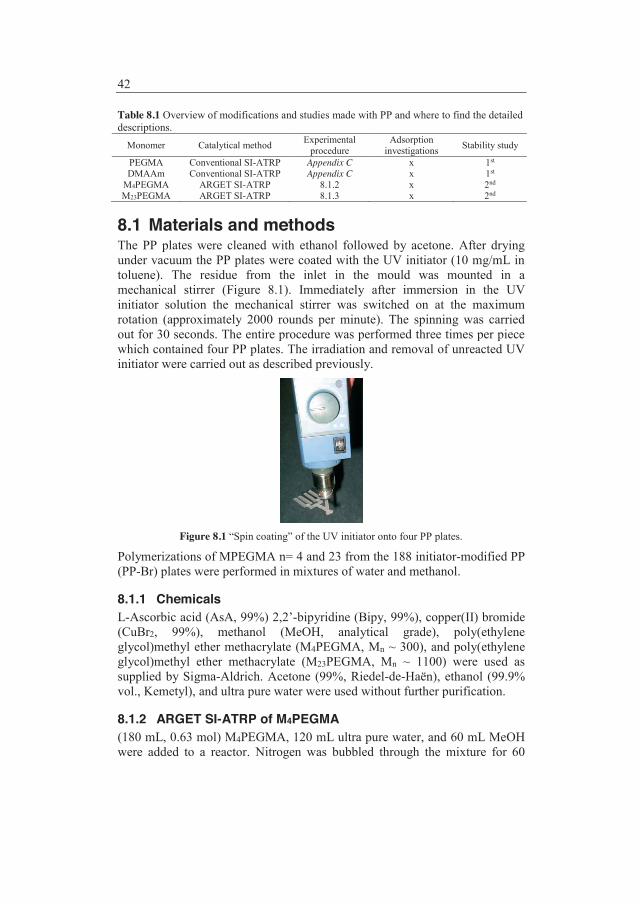
42
Table 8.1 Overview of modifications and studies made with PP and where to find the detailed descriptions.
Monomer Catalytical method Experimental procedure
Adsorption investigations Stability study
PEGMA Conventional SI-ATRP Appendix C x 1st DMAAm Conventional SI-ATRP Appendix C x 1st
M4PEGMA ARGET SI-ATRP 8.1.2 x 2nd M23PEGMA ARGET SI-ATRP 8.1.3 x 2nd
8.1 Materials and methods The PP plates were cleaned with ethanol followed by acetone. After drying under vacuum the PP plates were coated with the UV initiator (10 mg/mL in toluene). The residue from the inlet in the mould was mounted in a mechanical stirrer (Figure 8.1). Immediately after immersion in the UV initiator solution the mechanical stirrer was switched on at the maximum rotation (approximately 2000 rounds per minute). The spinning was carried out for 30 seconds. The entire procedure was performed three times per piece which contained four PP plates. The irradiation and removal of unreacted UV initiator were carried out as described previously.
Figure 8.1 “Spin coating” of the UV initiator onto four PP plates.
Polymerizations of MPEGMA n= 4 and 23 from the 188 initiator-modified PP (PP-Br) plates were performed in mixtures of water and methanol.
8.1.1 Chemicals L-Ascorbic acid (AsA, 99%) 2,2’-bipyridine (Bipy, 99%), copper(II) bromide (CuBr2, 99%), methanol (MeOH, analytical grade), poly(ethylene glycol)methyl ether methacrylate (M4PEGMA, Mn ~ 300), and poly(ethylene glycol)methyl ether methacrylate (M23PEGMA, Mn ~ 1100) were used as supplied by Sigma-Aldrich. Acetone (99%, Riedel-de-Haën), ethanol (99.9% vol., Kemetyl), and ultra pure water were used without further purification.
8.1.2 ARGET SI-ATRP of M4PEGMA (180 mL, 0.63 mol) M4PEGMA, 120 mL ultra pure water, and 60 mL MeOH were added to a reactor. Nitrogen was bubbled through the mixture for 60
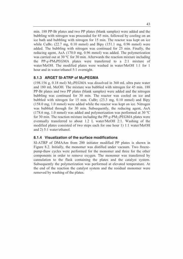
43
min. 188 PP-Br plates and two PP plates (blank samples) were added and the bubbling with nitrogen was proceeded for 45 min, followed by cooling on an ice bath and bubbling with nitrogen for 15 min. The reactor was kept on ice while CuBr2 (22.7 mg, 0.10 mmol) and Bipy (151.1 mg, 0.96 mmol) were added. The bubbling with nitrogen was continued for 25 min. Finally, the reducing agent, AsA (170.0 mg, 0.96 mmol) was added. The polymerization was carried out at 30 ºC for 30 min. Afterwards the reaction mixture including the PP-g-PM4PEGMA plates were transferred to a 2:1 mixture of water/MeOH. The modified plates were washed in water/MeOH 1:1 for 1 hour and in water/ethanol 5:1 overnight.
8.1.3 ARGET SI-ATRP of M23PEGMA (198.156 g, 0.18 mol) M23PEGMA was dissolved in 360 mL ultra pure water and 180 mL MeOH. The mixture was bubbled with nitrogen for 45 min. 188 PP-Br plates and two PP plates (blank samples) were added and the nitrogen bubbling was continued for 30 min. The reactor was cooled on ice and bubbled with nitrogen for 15 min. CuBr2 (23.3 mg, 0.10 mmol) and Bipy (158.0 mg, 1.0 mmol) were added while the reactor was kept on ice. Nitrogen was bubbled through for 30 min. Subsequently, the reducing agent, AsA (178.6 mg, 1.0 mmol) was added and polymerization was performed at 30 ºC for 30 min. The reaction mixture including the PP-g-PM23PEGMA plates were eventually transferred to about 1.2 L water/MeOH 2:1. Washing of the modified plates consisted of two steps each for one hour 1) 1:1 water/MeOH and 2) 5:1 water/ethanol.
8.1.4 Visualization of the surface modifications SI-ATRP of DMAAm from 200 initiator modified PP plates is shown in Figure 8.2. Initially, the monomer was distilled under vacuum. Two freeze-pump-thaw cycles were performed for the monomer and three for the other components in order to remove oxygen. The monomer was transferred by cannulation to the flask containing the plates and the catalyst system. Subsequently the polymerization was performed at elevated temperature. At the end of the reaction the catalyst system and the residual monomer were removed by washing of the plates.
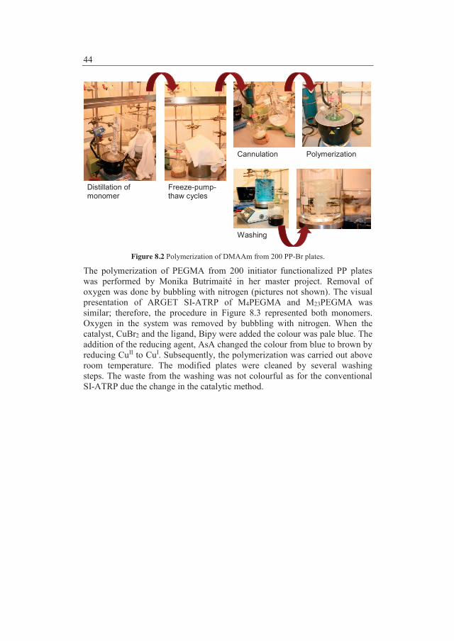
44
Figure 8.2 Polymerization of DMAAm from 200 PP-Br plates.
The polymerization of PEGMA from 200 initiator functionalized PP plates was performed by Monika Butrimaité in her master project. Removal of oxygen was done by bubbling with nitrogen (pictures not shown). The visual presentation of ARGET SI-ATRP of M4PEGMA and M23PEGMA was similar; therefore, the procedure in Figure 8.3 represented both monomers. Oxygen in the system was removed by bubbling with nitrogen. When the catalyst, CuBr2 and the ligand, Bipy were added the colour was pale blue. The addition of the reducing agent, AsA changed the colour from blue to brown by reducing CuII to CuI. Subsequently, the polymerization was carried out above room temperature. The modified plates were cleaned by several washing steps. The waste from the washing was not colourful as for the conventional SI-ATRP due the change in the catalytic method.
Distillation of monomer
Washing
Freeze-pump- thaw cycles
Cannulation Polymerization

45
Figure 8.3 The general modification procedure for grafting of the MPEGMA monomers from 188 PP-Br plates.
8.1.5 Scanning electron microscope analysis Images of the plates and insulin fibrils were obtained with conventional SEM and Field Emission SEM (FESEM), respectively. A coating of sputtered platinum was applied to the plates prior to SEM analysis with a Helios NanoLab™ dual beam, focused ion beam FIB-SEM from FEI. The samples were analyzed with a voltage of 5kV and a beam current of 21 pA. Moreover, the samples were tilted 51 degree. A droplet of the insulin fibrils from a 96-well microplate were placed directly on the SEM stub without drying. The images were obtained with beam deceleration on a Nova NanoSEM from FEI. The following settings were applied voltage 6.0 kV, beam current 15 pA, working distance 5-6 mm, beam landing energy 2.0 kV, immersion ratio 3.00, and a low voltage high contrast detector.
8.2 Modification of polypropylene Initiating groups for ATRP were first anchored on the PP surface before the graft polymerization could take place. Covalent C-C bonds were formed between the initiator and PP when irradiated with UV light at 365 nm. Hydrophilic chains of either poly(PEGMA) or poly(DMAAm) were grafted from the initiator modified PP surface by SI-ATRP (Figure 8.4).
Washing
Bubbling with nitrogen
Catalyst added Polymerization
Waste

46
PP
Br
Br
Br
1) Immersion inBP-iBuBr
2) UV irradiation
CuCl/BipyPEGMAH2O
45 min.at 30 ºC
CuCl/HMTETADMAAm
24 hat 90 ºC
Figure 8.4 Grafting of poly(PEGMA), n = 6.2 and poly(DMAAm) from the initiator functionalized PP surface.
The poly(MPEGMA) grafts n = 4 and 23, respectively were prepared by ARGET SI-ATRP. Moreover, the PP plates were coated with the UV initiator in a slightly more sophisticated way to avoid heterogeneous distribution of the poly(MPEGMA) layer (Figure 8.5). The procedures for the two MPEGMA monomers look identical; however, the ratio between monomer:H2O:MeOH differed. For M4PEGMA it was 3:2:1 whereas the mixture with M23PEGMA contained 1:2:1. The content of solvent was increased for M23PEGMA due to poor solubility of the monomer.
PP
Br
Br
Br
1) "Spin coating" of BP-iBuBr
2) UV irradiation
CuBr2/Bipy/AsAM4PEGMAH2O/MeOH
30 min.at 30 ºC
CuBr2/Bipy/AsAM23PEGMAH2O/MeOH
30 min.at 30 ºC
Figure 8.5 Simplified scheme of MPEGMA with 4 and 23 EO units, respectively in the side chain were grafted from PP by ARGET SI-ATRP.
From the ATR FTIR spectra (Figure 8.6) the presence of the poly(PEGMA), poly(DMAAm), and poly(MPEGMA) grafts on the PP substrates were observed. The carbonyl group (C=O) from the ester in the initiator and poly(PEGMA) resulted in a stretching band at 1734 cm-1. Surprisingly, the C=O stretching bands were not visable for the plates with poly(MPEGMA) grafts. The C=O absorption band from the amide in poly(DMAAm) appeared at 1634 cm-1. At 1256 cm-1 the C-O and C-N stretching bands were observed which were from the amide in poly(DMAAm) and the O=C-O in initiator, poly(PEGMA) and poly(MPEGMA). The C-O
H2C CCH3
C OO
PEGMA
CH2CH2O Hn
H2C C
C O
N
DMAAm
H
CH3
CH3
H2C CCH3
C OO
MPEGMA
CH2CH2O CH3n
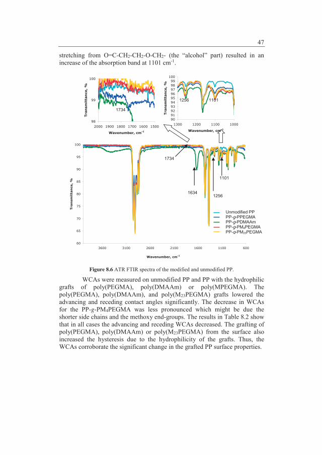
47
stretching from O=C-CH2-CH2-O-CH2- (the “alcohol” part) resulted in an increase of the absorption band at 1101 cm-1.
98
99
100
150016001700180019002000
Wavenumber, cm-1
Tran
smit
tan
ce,
%
90919293949596979899
100
1000110012001300
Wavenumber, cm-1
Tran
smit
tan
ce,
%
60
65
70
75
80
85
90
95
100
600110016002100260031003600
Wavenumber, cm-1
Tran
smit
tan
ce,
%
Figure 8.6 ATR FTIR spectra of the modified and unmodified PP.
WCAs were measured on unmodified PP and PP with the hydrophilic grafts of poly(PEGMA), poly(DMAAm) or poly(MPEGMA). The poly(PEGMA), poly(DMAAm), and poly(M23PEGMA) grafts lowered the advancing and receding contact angles significantly. The decrease in WCAs for the PP-g-PM4PEGMA was less pronounced which might be due the shorter side chains and the methoxy end-groups. The results in Table 8.2 show that in all cases the advancing and receding WCAs decreased. The grafting of poly(PEGMA), poly(DMAAm) or poly(M23PEGMA) from the surface also increased the hysteresis due to the hydrophilicity of the grafts. Thus, the WCAs corroborate the significant change in the grafted PP surface properties.
1734
1634 1256
1101
Unmodified PP PP-g-PPEGMA PP-g-PDMAAm PP-g-PM4PEGMA PP-g-PM23PEGMA
1734
1256 1101

48
Table 8.2 Dynamic WCA measurements on unmodified and modified PP. Material WCA (advancing), º WCA (receding), º Δ, °
PP 112 ± 1 87 ± 4 25 ± 4 PP-g-PPEGMA 83 ± 3 43 ± 2 40 ± 4 PP-g-PDMAAm 104 ± 2 49 ± 3 55 ± 3
PP-g-PM4PEGMA 106 ± 1 84 ± 3 22 ± 3 PP-g-PM23PEGMA 91 ± 1 39 ± 1 52 ± 1
8.2.1 Adsorption studies with labelled insulin When the applied ATRP conditions are used in solution it was revealed that some polymer chains have reacted with each other and formed crosslinks. The corresponding polymer brushes will presumably also crosslink.141 Nevertheless, all polymer grafts (crosslinked or non-crosslinked) were expected to inhibit protein adsorption when the modified substrates were immersed in a protein drug formulation. The proteins should perceive the hydrophilic polymer grafts as the aqueous media surrounding them. Thus the proteins were not supposed to denaturize or undergo conformational changes. Moreover, the proteins should not be physically adsorbed when the modified substrates were removed from the protein drug formulation.
Insulin aspart was labelled with the dye Alexa Fluor® 488 in borate buffer at pH 9.5 in order to use it for adsorption studies with confocal fluorescence microscopy. The conditions were not the same as in the formulation; however, it was not possible to lower pH to around 7 in the applied procedure. SEM images were obtained in order to decide which side was the most suitable for the confocal microscope analysis (Figure 8.7). The nubbly side was chosen as it had a pattern which was easier to bring into focus. The opposite side, the streaky side was applied for the WCA measurements. Modification of PP was not visible with the conventional SEM analysis which was performed (images not shown).
A B Figure 8.7 SEM images of tilted unmodified PP plates (A) was the streaky side whereas (B) was the nubbly side.
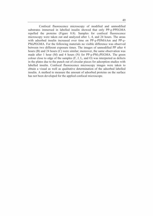
49
Confocal fluorescence microscopy of modified and unmodified substrates immersed in labelled insulin showed that only PP-g-PPEGMA repelled the proteins (Figure 8.8). Samples for confocal fluorescence microscopy were taken out and analyzed after 1, 4, and 24 hours. The areas with adsorbed insulin increased over time on PP-g-PDMAAm and PP-g-PM4PEGMA. For the following materials no visible difference was observed between two different exposure times. The images of unmodified PP after 4 hours (B) and 24 hours (C) were similar; moreover, the same observation was made after 1 hour (M) and 4 hours (N) for PP-g-PM23PEGMA. The green colour close to edge of the samples (F, J, L, and O) was interpreted as defects in the plates due to the punch out of circular pieces for adsorption studies with labelled insulin. Confocal fluorescence microscopy images were taken to obtain a visual as well as qualitative determination of the adsorbed labelled insulin. A method to measure the amount of adsorbed proteins on the surface has not been developed for the applied confocal microscope.

50
A B C
D E F
G H I
J K L
M N O
Figure 8.8 Overlay of images from transmission and confocal fluorescence microscopy of substrates immersed in labelled insulin. Unmodified PP after (A) 1 hour, (B) 4 hours, and (C) 24 hours; PP-g-PDMAAm after (D) 1 hour, (E) 4 hours, and (F) 24 hours; PP-g-PPEGMA after (G) 1 hour, (H) 4 hours, and (I) 24 hours; PP-g-PM4PEGMA after (J) 1 hour, (K) 4 hours, and (L) 24 hours; PP-g-PM23PEGMA after (M) 1 hour, (N) 4 hours, and (O) 24 hours.
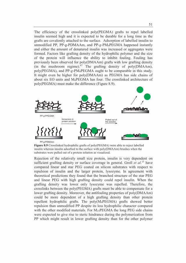
51
The efficiency of the crosslinked poly(PEGMA) grafts to repel labelled insulin seemed high and it is expected to be durable for a long time as the grafts are covalently attached to the surface. Adsorption of labelled insulin to unmodified PP, PP-g-PDMAAm, and PP-g-PM4PEGMA happened instantly and either the amount of denatured insulin was increased or aggregates were formed. Factors like grafting density of the hydrophilic polymer and the size of the protein will influence the ability to inhibit fouling. Fouling has previously been observed for poly(DMAAm) grafts with low grafting density (in the mushroom regime).47 The grafting density of poly(DMAAm), poly(PEGMA), and PP-g-PM4PEGMA ought to be comparable in this study. It might even be higher for poly(DMAAm) as PEGMA has side chains of about six EO units and M4PEGMA has four. The crosslinked architecture of poly(PEGMA) must make the difference (Figure 8.9).
Immersion inprotein solution
Pulled out of the solution
PP-g-PPEGMA
PP-g-PDMAAm
Figure 8.9 Crosslinked hydrophilic grafts of poly(PEGMA) were able to reject labelled insulin whereas insulin adsorbed to the surface with poly(DMAAm) brushes when the substrates were pulled out of a protein solution as visualized.
Rejection of the relatively small size protein, insulin is very dependent on sufficient grafting density or surface coverage in general. Groll et al.15 have compared linear and star PEG coated on silicon substrates with respect to repulsion of insulin and the larger protein, lysozyme. In agreement with theoretical predictions they found that the branched structure of the star PEG and linear PEG with high grafting density could repel insulin. When the grafting density was lower only lysozyme was repelled. Therefore, the crosslinks between the poly(PEGMA) grafts must be able to compensate for a lower grafting density. Moreover, the antifouling properties of poly(DMAAm) could be more dependent of a high grafting density than other protein repellent hydrophilic grafts. The poly(M4PEGMA) grafts showed better repulsion than unmodified PP despite its less hydrophilic character compared with the other modified materials. For M23PEGMA the long PEG side chains were expected to give rise to steric hindrance during the polymerization from PP which might result in lower grafting density than for the other polymer
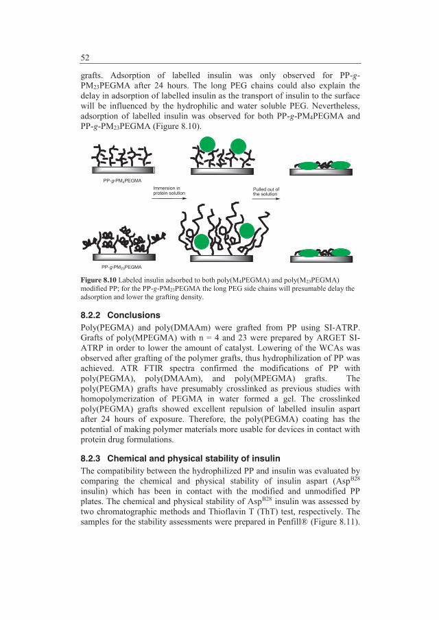
52
grafts. Adsorption of labelled insulin was only observed for PP-g-PM23PEGMA after 24 hours. The long PEG chains could also explain the delay in adsorption of labelled insulin as the transport of insulin to the surface will be influenced by the hydrophilic and water soluble PEG. Nevertheless, adsorption of labelled insulin was observed for both PP-g-PM4PEGMA and PP-g-PM23PEGMA (Figure 8.10).
Immersion inprotein solution
Pulled out of the solution
PP-g-PM4PEGMA
PP-g-PM23PEGMA Figure 8.10 Labeled insulin adsorbed to both poly(M4PEGMA) and poly(M23PEGMA) modified PP; for the PP-g-PM23PEGMA the long PEG side chains will presumable delay the adsorption and lower the grafting density.
8.2.2 Conclusions Poly(PEGMA) and poly(DMAAm) were grafted from PP using SI-ATRP. Grafts of poly(MPEGMA) with n = 4 and 23 were prepared by ARGET SI-ATRP in order to lower the amount of catalyst. Lowering of the WCAs was observed after grafting of the polymer grafts, thus hydrophilization of PP was achieved. ATR FTIR spectra confirmed the modifications of PP with poly(PEGMA), poly(DMAAm), and poly(MPEGMA) grafts. The poly(PEGMA) grafts have presumably crosslinked as previous studies with homopolymerization of PEGMA in water formed a gel. The crosslinked poly(PEGMA) grafts showed excellent repulsion of labelled insulin aspart after 24 hours of exposure. Therefore, the poly(PEGMA) coating has the potential of making polymer materials more usable for devices in contact with protein drug formulations.
8.2.3 Chemical and physical stability of insulin The compatibility between the hydrophilized PP and insulin was evaluated by comparing the chemical and physical stability of insulin aspart (AspB28 insulin) which has been in contact with the modified and unmodified PP plates. The chemical and physical stability of AspB28 insulin was assessed by two chromatographic methods and Thioflavin T (ThT) test, respectively. The samples for the stability assessments were prepared in Penfill® (Figure 8.11).

53
Two plates were inserted in each glass cartridge except for blank samples which did not contain any plates. The glass cartridges were equipped with rubber plungers and AspB28 insulin was transferred with a syringe. Finally, the cartridges were closed with caps.
Figure 8.11 Preparation of samples for a stability study.
AspB28 insulin stored in glass (blue cap bottle) was used as a reference because similar results are well-documented. Two studies have been conducted and in both studies the samples have been stored at 5, 20, and 37 °C; however, for the time being the maximum storage time for the samples taken out was 8 months for the first study and 4 months for the second. In the first study PP was coated with the hydrophilic polymer, poly(PEGMA) and poly(DMAAm). The second study included two different types of poly(MPEGMA) grafts with 4 and 23 EO in each monomer unit, respectively. The results from the studies will compare the influence of modified PP with the unmodified PP on the stability of AspB28 insulin. In Table 8.3 the different type of samples are listed. Table 8.3 List of sample names Type of samples Abbreviation Stored at 5 °C Stored at 20 °C Stored at 37 °C Reference AspB28 insulin Ref. Ref. Unmodified PP U U5 U20 U37 Poly(DMAAm) coating D D5 D20 D37 Poly(PEGMA) coating P P5 P20 P37 Blank sample B B5 B20 B37 Poly(M4PEGMA) coating 4M 4M5 4M20 4M37 Poly(M23PEGMA) coating 23M 23M5 23M20 23M37
Chemical stability is related to degradation of insulin by covalent changes. The chemical deterioration will result in formation of molecules which may be less active and undesirable. Two types of chemical reactions, intermolecular reactions and hydrolysis are involved in the chemical deterioration. The physical stability of AspB28 insulin was evaluated by the
Height: 3.5 cm Width: 0.6 cm Thickness: 0.1 cm

54
tendency to form fibrils. When insulin is exposed to e.g. hydrophobic surfaces, heat or shear forces, it can undergo conformational changes which will result in aggregation and formation of insulin fibrils.142
SEC and Reverse Phase HPLC (RP-HPLC) methods were applied to determine the amount of Higher Molecular Weight Proteins (HMWP) and the formation of hydrolysis products, respectively. HMWP are degradation products which are hydrophobic and consist of covalent bound dimers and polymers which are formed during storage of the insulin formulation. The covalent bonds were formed by disulfide exchange reactions or aminolysis between two A-chains in the insulin molecules or between an A-chain and a B-chain.142 The chromatograms from the RP-HPLC analysis also showed the preservative concentrations and assay of insulin in the samples. Each data point on the curves from the HPLC analyses was an average of two samples. However, the standard deviation was not included as the numbers from the two samples showed great resemblance as expected. In the following figures the line combining the measured values should serve as a guide to the eye and does not necessarily reflect values between the reported values. In RP-HPLC the insulin dimers and some oxidation products143,144 were designated as AspB28 insulin related impurities (Figure 8.12). PP with the poly(DMAAm) coating resulted in the highest content of AspB28 insulin related impurities.
0
5
10
15
20
25
30
35
40
0 2 4 6 8 10 12 14 16 18 20 22 24 26 28 30 32 34
Time, Weeks
Rela
ted
Impu
ritie
s, %
Ref.U37U20U5D37D20D5P37P20P5B37B20B5
Figure 8.12 AspB28 insulin related impurities in pct. relative to the total area for samples stored at 5, 20, and 37 °C; U=unmodified, D=poly(DMAAm) coating, P=poly(PEGMA) coating, B=blank, and Ref.=reference.
In the second stability study the differences between AspB28 insulin in contact with unmodified PP and poly(MPEGMA) coated PP were less pronounced. After a longer storage like the 8 months for the first study it might be possible to observe larger differences. The content of AspB28 insulin related impurities was slightly higher in the samples with poly(MPEGMA) coated plates stored at 37 °C (Figure 8.13). The change was not large enough to conclude that the poly(MPEGMA) coatings increased the chemical deterioration compared with unmodified PP. In general, the content of AspB28 insulin related impurities in samples was lower in the second stability study compared with the first.
37 °C

55
0
1
2
3
4
5
6
0 2 4 6 8 10 12 14 16
Time, Weeks
Rela
ted
Impu
ritie
s, %
Ref.U37U20U523M3723M2023M54M374M204M5B37B20B5
Figure 8.13 AspB28 insulin related impurities from the second stability study in pct. to the total area for samples stored 5, 20, and 37 °C; U=unmodified, 23M=poly(M23PEGMA) coating, 4M=poly(M4PEGMA) coating, B=blank, and Ref.=reference.
The phenol concentration and pH were not influenced by poly(MPEGMA) coatings. On the hand, major changes were observed due to the poly(DMAAm) coating in the first study. Therefore, results from the first study and possible explanations will be outlined below.
A decrease in the content of phenol is observed in the samples exposed to poly(DMAAm) coating (Figure 8.14). This can either be explained by depletion through adsorption to the poly(DMAAm) coating or by degradation of phenol due to the coating. In any case, it can be concluded that the poly(DMAAm) coating has a high affinity to preservatives in the drug formulation. AspB28 insulin will despite its monomeric character form hexamers in the presence of zinc ions and phenol or phenol-like molecules.145 The monomers in the hexamer are either in the T or R state. In the T state the residues B1-B9 adopt an elongated conformation whereas they form α-helix in the R state, resulting in one α-helix from B1-B20. Three conformational states are known for the hexamer T6 (all monomers in the T state), T3R3 (monomers alternating between T and R state), and R6 (all monomers in the R state).145,146 Insulin binds phenol and the compact and stable R6 hexamer is formed. If less phenol is present the less stable T6 will be formed. With the experimental conditions reported by Derewenda et al.146 it was concluded that the phenol concentration had an influence on the physical stability. However, the phenol concentration required for stabilizing the R6 hexamer146 is lower than the phenol concentration in the present formulation as phenol here also serves as a preservative. Nevertheless, it can not be ruled out that the shift in the phenol concentration observed in samples exposed to the poly(DMAAm) coating may have an effect on the physical stability of AspB28 insulin.
37 °C
20 °C
5 °C

56
70
75
80
85
90
95
100
105
0 2 4 6 8 10 12 14 16 18 20 22 24 26 28 30 32 34
Time, Weeks
Phen
ol, %
Ref.U37U20U5D37D20D5P37P20P5B37B20B5
Figure 8.14 Phenol concentration in pct. relative to blank sample for the samples stored at 5, 20, and 37 °C; U=unmodified, D=poly(DMAAm) coating, P=poly(PEGMA) coating, B=blank, and Ref.=reference.
Insulin degrades relatively fast below pH 5 and above pH 8. The optimum pH range for insulin was 6-7. At acidic pH values deamidation at residue A21 and formation of covalent insulin dimers will dominate whereas alkaline pH values will result in disulfide reactions. Formation of covalent insulin dimers and oligomers has an optimum around pH 4 and above pH 9 an accelerated formation of covalent oligomers and polymers was observed due to disulfide interchange reactions. Hydrolysis of insulin has a minimum at pH 6.5.142 The increase in pH for AspB28 insulin which has been in contact with the poly(DMAAm) coating (Figure 8.15) is consistent with increase in AspB28 insulin related impurities. The content of AspB28 insulin deamidation products (AspB3 + AspA21 + isoAspB3, data not shown) was also higher when it was exposed to poly(DMAAm). The observation confirmed that hydrolysis of insulin will increase if pH is increased from 7.35 to above 8. The increase in the pH value which was observed in the poly(DMAAm) samples might also contribute to stabilization of AspB28 insulin. Changes in pH can be due to leachables. Analysis with Inductive Coupled Plasma Optical Emission Spectroscopy (ICP-OES) showed that AspB28 insulin exposed to the poly(DMAAm) coating and stored at 37 °C for 20 weeks contained 7.2 μM copper (0.46 μg/mL) whereas the potential copper content in other samples was below the detection limit of 0.8 μM (0.05 μg/mL). The copper contamination most likely originates from the catalyst, which is applied for the SI-ATRP. Divalent metal ions are known to be capable of oxidizing insulin and increase pH. A spread of ± 0.3 in the pH values was measured for

57
some samples containing the poly(DMAAAm) coating and stored at 37 °C which can be due to heterogeneous distribution of the coating.
7.2
7.4
7.6
7.8
8.0
8.2
8.4
0 2 4 6 8 10 12 14 16 18 20 22 24 26 28 30 32 34
Time, Weeks
pH
Ref.U37U20U5D37D20D5P37P20P5B37B20B5
Figure 8.15 pH for all samples stored at 5, 20, and 37 °C; U=unmodified, D=poly(DMAAm) coating, P=poly(PEGMA) coating, B=blank, and Ref.=reference.
To investigate the tendency of insulin to fibrillate the ThT test was used. Insulin which has been exposed to modified or unmodified PP was compared with reference insulin and blank samples. Insulin and the dye ThT was transferred to 96-well microplates and placed in fluorescence plate-reader. ThT will bind to the insulin fibrils and its excitation and emission spectra will be shifted from maxima at 430 and 342 nm to 482 and 442 nm. When insulin fibrillates the ThT fluorescence intensity versus time will form a sigmoidal curve (Figure 8.16) consisting of a lag phase, a growth phase, and an equilibrium phase. From the ThT curve lag time, rate constant, and maximum intensity (Imax) can be determined by manual readings. The rate constant was obtained from the slope of the growth phase (Δ(fluorescence intensity)/ΔTime).
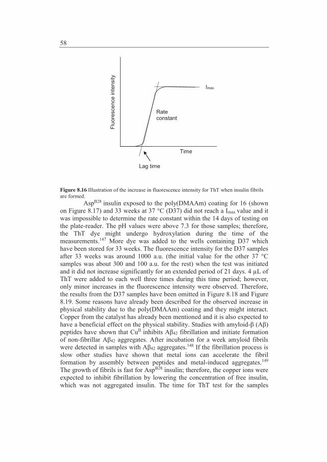
58
Figure 8.16 Illustration of the increase in fluorescence intensity for ThT when insulin fibrils are formed.
AspB28 insulin exposed to the poly(DMAAm) coating for 16 (shown on Figure 8.17) and 33 weeks at 37 °C (D37) did not reach a Imax value and it was impossible to determine the rate constant within the 14 days of testing on the plate-reader. The pH values were above 7.3 for those samples; therefore, the ThT dye might undergo hydroxylation during the time of the measurements.147 More dye was added to the wells containing D37 which have been stored for 33 weeks. The fluorescence intensity for the D37 samples after 33 weeks was around 1000 a.u. (the initial value for the other 37 °C samples was about 300 and 100 a.u. for the rest) when the test was initiated and it did not increase significantly for an extended period of 21 days. 4 μL of ThT were added to each well three times during this time period; however, only minor increases in the fluorescence intensity were observed. Therefore, the results from the D37 samples have been omitted in Figure 8.18 and Figure 8.19. Some reasons have already been described for the observed increase in physical stability due to the poly(DMAAm) coating and they might interact. Copper from the catalyst has already been mentioned and it is also expected to have a beneficial effect on the physical stability. Studies with amyloid-β (Aβ) peptides have shown that CuII inhibits Aβ42 fibrillation and initiate formation of non-fibrillar Aβ42 aggregates. After incubation for a week amyloid fibrils were detected in samples with Aβ42 aggregates.148 If the fibrillation process is slow other studies have shown that metal ions can accelerate the fibril formation by assembly between peptides and metal-induced aggregates.149 The growth of fibrils is fast for AspB28 insulin; therefore, the copper ions were expected to inhibit fibrillation by lowering the concentration of free insulin, which was not aggregated insulin. The time for ThT test for the samples
Time
Fluo
resc
ence
inte
nsity
Imax
Lag time
Rate constant

59
stored for 16 weeks was also extended until 21 days and the AspB28 insulin exposed to poly(DMAAm) coating reached a very low Imax value compared with other samples. Moreover, the Imax values for the AspB28 insulin in contact with unmodified PP or the poly(PEGMA) coating were lower than the blank sample. Differences in the fibril structures could be an explanation; therefore, SEM images of the AspB28 insulin fibrils from the ThT test were compared (Figure 8.17). AspB28 insulin fibrils were observed as thread-like structures which were more compact for (A) – (C) than (D). The difference in the fibrillar structure could explain the lower Imax values due to unmodified PP and the poly(PEGMA) coating. Furthermore, (B) contained almost no fibrils. Yoshiike et al.150 reported that ZnII or CuII prevent β-aggregation i.e. ThT reactive fibril formation. The CuII present in the poly(DMAAm) sample might therefore not only inhibit the AspB28 insulin fibril formation but also suppress it. If image (B) was compared with the others it looked like the final level of ThT reactive fibrils was suppressed. The suppression of ThT reactive fibrils conformed to the very low Imax value for the poly(DMAAm) samples.
A B
C D Figure 8.17 SEM images of the AspB28 insulin fibrils from the ThT test; AspB28 insulin has prior to the test been exposed to the unmodified PP (A), the poly(DMAAm) coating (B), the poly(PEGMA) coating (C) and AspB28 insulin from the blank sample (D); all samples have been stored 16 weeks at 37 °C.
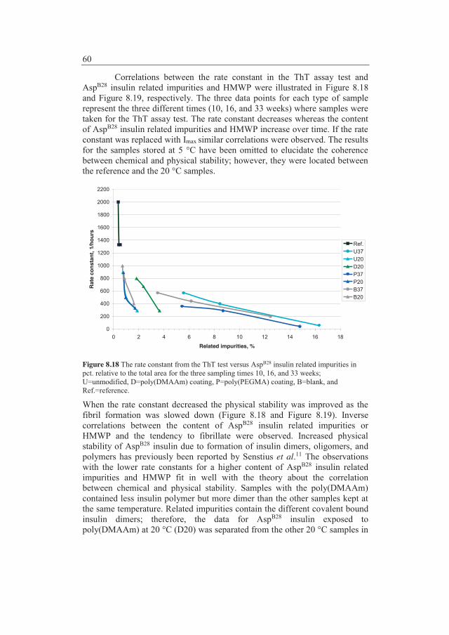
60
Correlations between the rate constant in the ThT assay test and AspB28 insulin related impurities and HMWP were illustrated in Figure 8.18 and Figure 8.19, respectively. The three data points for each type of sample represent the three different times (10, 16, and 33 weeks) where samples were taken for the ThT assay test. The rate constant decreases whereas the content of AspB28 insulin related impurities and HMWP increase over time. If the rate constant was replaced with Imax similar correlations were observed. The results for the samples stored at 5 °C have been omitted to elucidate the coherence between chemical and physical stability; however, they were located between the reference and the 20 °C samples.
0
200
400
600
800
1000
1200
1400
1600
1800
2000
2200
0 2 4 6 8 10 12 14 16 18
Related impurities, %
Rate
con
stan
t, 1/
hour
s
Ref.U37U20D20P37P20B37B20
Figure 8.18 The rate constant from the ThT test versus AspB28 insulin related impurities in pct. relative to the total area for the three sampling times 10, 16, and 33 weeks; U=unmodified, D=poly(DMAAm) coating, P=poly(PEGMA) coating, B=blank, and Ref.=reference.
When the rate constant decreased the physical stability was improved as the fibril formation was slowed down (Figure 8.18 and Figure 8.19). Inverse correlations between the content of AspB28 insulin related impurities or HMWP and the tendency to fibrillate were observed. Increased physical stability of AspB28 insulin due to formation of insulin dimers, oligomers, and polymers has previously been reported by Senstius et al.11 The observations with the lower rate constants for a higher content of AspB28 insulin related impurities and HMWP fit in well with the theory about the correlation between chemical and physical stability. Samples with the poly(DMAAm) contained less insulin polymer but more dimer than the other samples kept at the same temperature. Related impurities contain the different covalent bound insulin dimers; therefore, the data for AspB28 insulin exposed to poly(DMAAm) at 20 °C (D20) was separated from the other 20 °C samples in
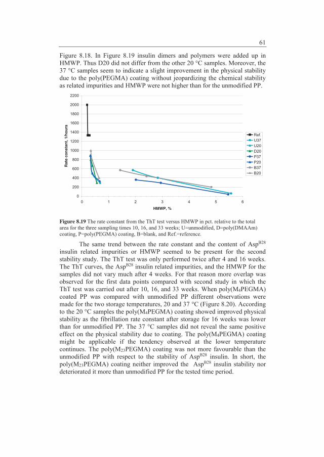
61
Figure 8.18. In Figure 8.19 insulin dimers and polymers were added up in HMWP. Thus D20 did not differ from the other 20 °C samples. Moreover, the 37 °C samples seem to indicate a slight improvement in the physical stability due to the poly(PEGMA) coating without jeopardizing the chemical stability as related impurities and HMWP were not higher than for the unmodified PP.
0
200
400
600
800
1000
1200
1400
1600
1800
2000
2200
0 1 2 3 4 5 6
HMWP, %
Rate
con
stan
t, 1/
hour
s
Ref.U37U20D20P37P20B37B20
Figure 8.19 The rate constant from the ThT test versus HMWP in pct. relative to the total area for the three sampling times 10, 16, and 33 weeks; U=unmodified, D=poly(DMAAm) coating, P=poly(PEGMA) coating, B=blank, and Ref.=reference.
The same trend between the rate constant and the content of AspB28 insulin related impurities or HMWP seemed to be present for the second stability study. The ThT test was only performed twice after 4 and 16 weeks. The ThT curves, the AspB28 insulin related impurities, and the HMWP for the samples did not vary much after 4 weeks. For that reason more overlap was observed for the first data points compared with second study in which the ThT test was carried out after 10, 16, and 33 weeks. When poly(M4PEGMA) coated PP was compared with unmodified PP different observations were made for the two storage temperatures, 20 and 37 °C (Figure 8.20). According to the 20 °C samples the poly(M4PEGMA) coating showed improved physical stability as the fibrillation rate constant after storage for 16 weeks was lower than for unmodified PP. The 37 °C samples did not reveal the same positive effect on the physical stability due to coating. The poly(M4PEGMA) coating might be applicable if the tendency observed at the lower temperature continues. The poly(M23PEGMA) coating was not more favourable than the unmodified PP with respect to the stability of AspB28 insulin. In short, the poly(M23PEGMA) coating neither improved the AspB28 insulin stability nor deteriorated it more than unmodified PP for the tested time period.

62
0
200
400
600
800
1000
1200
1400
1600
1800
2000
2200
0 1 2 3 4 5 6
Related impurities, %
Rate
con
stan
t, 1/
hour
s
Ref.U37U2023M3723M204M374M20B37B20
0
200
400
600
800
1000
1200
1400
1600
1800
2000
2200
0 1 2 3
HMWP, %
Rate
con
stan
t, 1/
hour
s
Ref.U37U2023M3723M204M374M20B37B20
Figure 8.20 The rate constant from the ThT test versus (A) AspB28 insulin related impurities and (B) HMWP in pct. relative to the total area for the two sampling times 4 and 16 weeks; U=unmodified, 23M=poly(M23PEGMA) coating, 4M=poly(M4PEGMA) coating, B=blank, and Ref.=reference.
8.2.4 Conclusions In general, AspB28 insulin related impurities and HMWP were observed to correlate inversely with the increased physical stability. Cause and effect have not been clarified; however, the observations pointed towards coherence between the chemical and physical stability of AspB28 insulin. The poly(DMAAm) coating showed a high affinity to the preservatives in
A
B
4 weeks
4 weeks
16 weeks
16 weeks
16 weeks
16 weeks
4 weeks
4 weeks

63
consequence a lower phenol concentration was observed which cannot be excluded to have an effect on the physical stability. Moreover, the poly(DMAAm) resulted in the highest content of AspB28 insulin related impurities. The increase in pH was consistent with the increase in AspB28 insulin related impurities due to poly(DMAAm). 7.2 μM copper from the catalyst was detected in the samples with poly(DMAAm) coated PP and the copper might oxidize insulin and increase pH. It cannot be ruled out that the copper from the catalyst will also contribute to improved physical stability as CuII is expected to inhibit fibrillation for AspB28 insulin. Finally, the poly(DMAAm) samples contained less AspB28 insulin polymer but more dimer than the other samples kept at the same temperature.
The poly(PEGMA) coating resulted in improved stability of AspB28 insulin compared to unmodified PP and the poly(DMAAm) coating. The improvement of the stability was especially evident for the samples stored at 37 °C when the samples have been stored for eight months. The data observed for the accelerated conditions (37 °C) have the same trend as data observed at 5 and 20 °C. The observed improvement may therefore be expected to be predictive of long term stability at 5 and 20 °C. Poly(PEGMA) coating of PP surfaces in primary packaging materials for AspB28 insulin is thus expected to have a pronounced positive effect on the AspB28 insulin stability.
The influence on the AspB28 insulin stability due to poly(MPEGMA) coatings was vague when it was compared with unmodified PP. Prolonged storage time might give more lucid results. Dependence on the storage temperature was observed when the tendency to form fibrils was compared for poly(M4PEGMA) coated PP and the unmodified PP. For the 20 °C samples the poly(M4PEGMA) coating resulted in the lowest fibrillation rate constant whereas the fibrillation rate constant was lower for unmodified PP when the samples were stored at 37 °C. Table 8.4 summarizes the influence of the coatings on the results compared to the unmodified PP. Table 8.4 Results for AspB28 insulin after exposure to the coated PP compared with unmodified PP; green is a favorable result whereas red is unfavorable; the arrows indicate whether the value increases (↑), decreases (↓) or stays at the same level (→) compared to samples exposed to unmodified PP.
Coating AspB28 insulin related impurities HMWP Fibrillation
rate constant Phenol pH Copper
Poly(DMAAm) ↑ ↑ ↓ ↓ ↑ ↑ Poly(PEGMA) ↓ ↓ ↓ → → → Poly(M4PEGMA) → → ↓↑ → → * Poly(M23PEGMA) → → ↑ → → *
* ICP-OES was not performed on the samples in the second stability study.
SEM images of AspB28 insulin fibrils from the first stability study visualized the suppression of fibrillation and changes in the fibrillar structure which in both causes have been observed as lower Imax values in the ThT test.
Considerations like sterilization and permeability will have to be considered before PP coated with poly(PEGMA) can be applied in a stability

64
study which compares the polymeric material with glass. However, this study has proven that a material like poly(PEGMA) coated PP has the possibility of replacing glass for storage of a drug product formulation.
65
9 Concluding remarks Hydrophilization of the model substrate, PEEK was achieved by SI-ATRP of PEGMA. The PEEK film acted as a very good model system in the different modifications steps. It was possible to use various characterization methods to confirm the modifications e.g. AFM, TGA, WCA and XPS. ATR-FTIR spectroscopy of initiator functionalized PEEK films even revealed the carbonyl group in the ATRP initiator which was very unique. PEEK-g-poly(PEGMA) is applicable for inhibition of non-specific fouling due the hydrophilicity of the material. However, autofluorescence of the material made it impossible to apply confocal fluorescence microscopy to study the expected non-fouling properties.
A benzophenone containing UV initiator was synthesized and applied to prepare PP plates for SI-ATRP. The experimental work with PP plates was carried out in two rounds. Firstly, poly(PEGMA) and poly(DMAAm) were grafted from PP by conventional SI-ATRP. Secondly, grafts of poly(MPEGMA) with n = 4 and 23 EO units in the side chains, respectively were prepared by ARGET SI-ATRP in order to decrease the amount of catalyst. It was decided to change the catalytical method as metal analysis by ICP-OES showed that the insulin exposed to PP-g-PDMAAm plates contained copper. The presence of the polymer grafts was confirmed with ATR-FTIR spectroscopy. Results from WCA measurements showed that hydrophilization of PP was obtained by preparation of the polymer grafts.
The ability of modified and unmodified PP to repel labelled AspB28 insulin was investigated by confocal fluorescence microscopy. The crosslinked poly(PEGMA) grafts were the only ones which showed excellent repulsion of labelled AspB28 insulin after 24 hours of exposure. Two stability studies were conducted in which the stability of AspB28 insulin in contact with either modified PP or unmodified PP was compared. PP-g-PPEGMA and PP-g-PDMAAm plates were employed in the first stability study and results after 8 months of storages have been obtained. The second stability study with PP-g-PM4PEGMA and PP-g-PM23PEGMA plates was set up after the first and it has been going for 4 months until now. PP with the poly(PEGMA) coating was the only material which resulted in better stability of AspB28 insulin than unmodified PP. The results from the poly(DMAAm) coating showed improved physical stability; however, the chemical stability of AspB28 insulin was very poor. In the tested period the poly(MPEGMA) coatings have not shown significant differences in neither chemical stability nor physical stability compared with unmodified PP.
The overall objective of the PhD project was accomplished as PP-g-PPEGMA showed eminent repulsion of labelled AspB28 insulin. Moreover, chemical and physical stability of AspB28 insulin was significantly improved after 8 months of exposure to PP-g-PPEGMA compared with unmodified PP.
66
10 Outlook Low grafting density could be one of the explanations for the absence of protein repulsion for the poly(DMAAm) and poly(M4PEGMA). It is possible that the applied UV initiator does not supply enough initiating sites to obtain a sufficient grafting density. Therefore, it would be interesting to try to find a more effective method to activate PP and compare the anti-fouling properties after SI-ATRP.
The poly(PEGMA) grafts can be prepared in methanol without croslinking, thus PEGMA grafting from PP should be performed in methanol. An adsorption study with labelled AspB28 insulin is expected to show adsorption on the poly(PEGMA) coating prepared in methanol. If this study is carried out the theory about the anti-fouling crosslinks could be confirmed.
The molecular weight of the polymer grafts has not been determined as it requires a large surface area to have enough material for SEC analysis. It is very time-consuming to modify a large amount of plates with the UV initiator. However, a study in which the molecular weight can be determined has to be carried out either on many of the already applied plates or some larger plates have to be moulded.
Metal analysis of the samples in the second stability studyy is not expected to reveal any copper from the catalyst as the stability of AspB28 insulin has not changed significantly during the first four months. However, in order to confirm that copper from the catalyst is not present ICP-OES should be performed. Further investigations of the poly(PEGMA) coated PP have to be made before the material can be used for container or devices in contact with insulin. Sterilization of PP-g-PPEGMA by e.g. steam should be performed and any impact on e.g. the shape, transparency, and the mechanical properties should not be observed. Moreover, the permeability of PP-g-PPEGMA should be studied and the material should not be permeable to water or any gasses. Finally, a stability study should be set up which should be as close to reality as possible. PEGMA should be grafted from PP containers and the modified containers should be compared with glass.

67
11 References [1] A. Nayak, A.K. Dutta, and G. Belfort, Surface-enhanced nucleation of
insulin amyloid fibrillation, Biochem. Biophys. Res. Commun., 369 (2008) 303-307.
[2] H. Thurow and K. Geisen, Stabilisation of Dissolved Proteins against Denaturation at Hydrophobic Interfaces, Diabetologia, 27 (1984) 212-2.
[3] M.I. Smith, J.S. Sharp, and C.J. Roberts, Nucleation and growth of insulin fibrils in bulk solution and at hydrophobic polystyrene surfaces, Biophys. J., 93 (2007) 2143-2151.
[4] M. Zhu, P.O. Souillac, C. Ionescu-Zanetti, S.A. Carter, and A.L. Fink, Surface-catalyzed amyloid fibril formation, J. Biol. Chem., 277 (2002) 50914-50922.
[5] J. Brange, L. Andersen, E.D. Laursen, G. Meyn, and E. Rasmussen, Toward understanding insulin fibrillation, J. Pharm. Sci., 86 (1997) 517-525.
[6] L. Nielsen, R. Khurana, A. Coats, S. Frokjaer, J. Brange, S. Vyas, V.N. Uversky, and A.L. Fink, Effect of environmental factors on the kinetics of insulin fibril formation: Elucidation of the molecular mechanism, Biochemistry, 40 (2001) 6036-6046.
[7] V. Sluzky, J.A. Tamada, A.M. Klibanov, and R. Langer, Kinetics of Insulin Aggregation in Aqueous Solutions upon Agitation in the Presence of Hydrophobic Surfaces, Proc. Natl. Acad. Sci. USA, 88 (1991) 9377-9381.
[8] B. Vestergaard, M. Groenning, M. Roessle, J.S. Kastrup, M. van de Weert, J.M. Flink, S. Frokjaer, M. Gajhede, and D.I. Svergun, A helical structural nucleus is the primary elongating unit of insulin amyloid fibrils, Plos Biology, 5 (2007) 1089-1097.
[9] T. Arnebrant and T. Nylander, Adsorption of Insulin on Metal-Surfaces in Relation to Association Behavior, J. Colloid Interface Sci., 122 (1988) 557-566.
[10] P. Nilsson, T. Nylander, and S. Havelund, Adsorption of Insulin on Solid-Surfaces in Relation to the Surface-Properties of the Monomeric and Oligomeric Forms, J. Colloid Interface Sci., 144 (1991) 145-152.
68
[11] J. Senstius, C. Poulsen, and A. Hvass, Comparison of in vitro stability for insulin aspart and insulin glulisine during simulated use in infusion pumps, Diabetes Technol. Ther., 9 (2007) 517-521.
[12] J.H. Lee, H.B. Lee, and J.D. Andrade, Blood Compatibility of Polyethylene Oxide Surfaces, Prog. Polym. Sci., 20 (1995) 1043-1079.
[13] D.L. Elbert and J.A. Hubbell, Surface treatments of polymers for biocompatibility, Annu. Rev. Mater. Sci., 26 (1996) 365-394.
[14] M. Malmsten, K. Emoto, and J.M. Van Alstine, Effect of chain density on inhibition of protein adsorption by poly(ethylene glycol) based coatings, J. Colloid Interface Sci., 202 (1998) 507-517.
[15] J. Groll, Z. Ademovic, T. Ameringer, D. Klee, and M. Moeller, Comparison of Coatings from Reactive Star Shaped PEG-stat-PPG Prepolymers and Grafted Linear PEG for Biological ans Medical Applications, Biomacromolecules, 6 (2005) 956-962.
[16] K.L. Prime and G.M. Whitesides, Adsorption of Proteins Onto Surfaces Containing End-Attached Oligo(Ethylene Oxide) - A Model System Using Self-Assembled Monolayers, J. Am. Chem. Soc., 115 (1993) 10714-10721.
[17] K. Bergstrom, E. Osterberg, K. Holmberg, A.S. Hoffman, T.P. Schuman, A. Kozlowski, and J.M. Harris, Effects of Branching and Molecular-Weight of Surface-Bound Poly(Ethylene Oxide) on Protein Rejection, J. Biomat. Sci. -Polym. E., 6 (1994) 123-132.
[18] M.E. Norman, P. Williams, and L. Illum, Human Serum-Albumin As A Probe for Surface Conditioning (Opsonization) of Block Copolymer-Coated Microspheres, Biomaterials, 13 (1992) 841-849.
[19] J.S. Tan, D.E. Butterfield, C.L. Voycheck, K.D. Caldwell, and J.T. Li, Surface Modification of Nanoparticles by Peo Ppo Block-Copolymers to Minimize Interactions with Blood Components and Prolong Blood-Circulation in Rats, Biomaterials, 14 (1993) 823-833.
[20] K. Kato, S. Sano, and Y. Ikada, Protein Adsorption Onto Ionic Surfaces, Colloids Surf. , B, 4 (1995) 221-230.
[21] N.P. Desai and J.A. Hubbell, Solution Technique to Incorporate Polyethylene Oxide and Other Water-Soluble Polymers onto Surfaces of Polymeric Biomaterials, Biomaterials, 12 (1991) 144-1.
69
[22] N.P. Desai and J.A. Hubbell, Biological Responses to Polyethylene Oxide Modified Polyethylene Terephthalate Surfaces, J. Biomed. Mater. Res., 25 (1991) 829-843.
[23] S.G. Shafer and J.M. Harris, Preparation of Cyanuric-Chloride Activated Poly(Ethylene Glycol), J. Polym. Sci. , Part A: Polym. Chem., 24 (1986) 375-378.
[24] X.P. Zou, E.T. Kang, and K.G. Neoh, Plasma-induced graft polymerization of poly(ethylene glycol) methyl ether methacrylate on poly (tetrafluoroethylene) films for reduction in protein adsorption, Surf. Coat. Technol., 149 (2002) 119-128.
[25] R.B. Timmons and A.J. Griggs, Pulsed Plasma Polymerizations, in: H. Biederman (Ed.), Plasma Polymer Films, Imperial College Press, London, 2004, pp. 217-245.
[26] H. Biederman, Introduction, in: H. Biederman (Ed.), Plasma Polymer Films, Imperial College Press, London, 2004, pp. 13-24.
[27] F. Zhou and W.T.S. Huck, Surface grafted polymer brushes as ideal building blocks for ''smart'' surfaces, Phys. Chem. Chem. Phys., 8 (2006) 3815-3823.
[28] J.S. Wang and K. Matyjaszewski, Controlled Living Radical Polymerization - Atom-Transfer Radical Polymerization in the Presence of Transition-Metal Complexes, J. Am. Chem. Soc., 117 (1995) 5614-5615.
[29] M. Kato, M. Kamigaito, M. Sawamoto, and T. Higashimura, Polymerization of Methyl-Methacrylate with the Carbon-Tetrachloride Dichlorotris(Triphenylphosphine)Ruthenium(Ii) Methylaluminum Bis(2,6-Di-Tert-Butylphenoxide) Initiating System - Possibility of Living Radical Polymerization, Macromolecules, 28 (1995) 1721-1723.
[30] WO 9630421A1 (Matyjaszewski, K., Wang, J.) 3 October 1996.
[31] C.P. Chen, B.T. Ko, S.L. Lin, M.Y. Hsu, and C. Ting, Hydrophilic polymer supports grafted by poly(ethylene glycol) derivatives via atom transfer radical polymerization, Polymer, 47 (2006) 6630-6635.
[32] Z.P. Cheng, X.L. Zhu, Z.L. Shi, K.G. Neoh, and E.T. Kang, Polymer microspheres with permanent antibacterial surface from surface-initiated atom transfer radical polymerization, Ind. Eng. Chem. Res., 44 (2005) 7098-7104.

70
[33] Z.P. Cheng, X.L. Zhu, Z.L. Shi, K.G. Neoh, and E.T. Kang, Polymer microspheres with permanent antibacterial surface from surface-initiated atom transfer radical polymerization of 4-vinylpyridine and quaternization, Surf. Rev. Lett., 13 (2006) 313-318.
[34] A. Mizutani, A. Kikuchi, M. Yamato, H. Kanazawa, and T. Okano, Preparation of thermoresponsive polymer brush surfaces and their interaction with cells, Biomaterials, 29 (2008) 2073-2081.
[35] Y.W. Chen, D.M. Liu, Q.L. Deng, X.H. He, and X.F. Wang, Atom transfer radical polymerization directly from poly(vinylidene fluoride): Surface and antifouling properties, J. Polym. Sci. , Part A: Polym. Chem., 44 (2006) 3434-3443.
[36] J.F. Hester, P. Banerjee, Y.Y. Won, A. Akthakul, M.H. Acar, and A.M. Mayes, ATRP of amphiphilic graft copolymers based on PVDF and their use as membrane additives, Macromolecules, 35 (2002) 7652-7661.
[37] C.J. Fristrup, K. Jankova, and S. Hvilsted, Surface-initiated atom transfer radical polymerization-a technique to develop biofunctional coatings, Soft Matter, 5 (2009) 4623-4634.
[38] P. Liu, Modification of polymeric materials via surface-initiated controlled/"living" radical polymerization, E-Polymers, (2007).
[39] D. Roy, M. Semsarilar, J.T. Guthrie, and S. Perrier, Cellulose modification by polymer grafting: a review, Chem. Soc. Rev., 38 (2009) 2046-2064.
[40] B. Radhakrishnan, R. Ranjan, and W.J. Brittain, Surface initiated polymerizations from silica nanoparticles, Soft Matter, 2 (2006) 386-396.
[41] C.M. Homenick, G. Lawson, and A. Adronov, Polymer grafting of carbon nanotubes using living free-radical polymerization, Polymer Reviews, 47 (2007) 265-290.
[42] R. Barbey, L. Lavanant, D. Paripovic, N. Schuwer, C. Sugnaux, S. Tugulu, and H.A. Klok, Polymer Brushes via Surface-Initiated Controlled Radical Polymerization: Synthesis, Characterization, Properties, and Applications, Chem. Rev., 109 (2009) 5437-5527.
[43] F.J. Xu, K.G. Neoh, and E.T. Kang, Bioactive surfaces and biomaterials via atom transfer radical polymerization, Prog. Polym. Sci., 34 (2009) 719-761.
71
[44] N. Singh, J. Wang, M. Ulbricht, S.R. Wickramasinghe, and S.M. Husson, Surface-initiated atom transfer radical polymerization: A new method for preparation of polymeric membrane adsorbers, J. Membr. Sci., 309 (2008) 64-72.
[45] S.B. Lee, R.R. Koepsel, S.W. Morley, K. Matyjaszewski, Y.J. Sun, and A.J. Russell, Permanent, nonleaching antibacterial surfaces. 1. Synthesis by atom transfer radical polymerization, Biomacromolecules, 5 (2004) 877-882.
[46] D. Bozukova, C. Pagnoulle, M.C. Pauw-Gillet, N. Ruth, R. Jerome, and C. Jerome, Imparting antifouling properties of poly(2-hydroxyethyl methacrylate) hydrogels by grafting poly(oligoethylene glycol methyl ether acrylate), Langmuir, 24 (2008) 6649-6658.
[47] B.R. Coad, B.M. Steels, J.N. Kizhakkedathu, D.E. Brooks, and C.A. Haynes, The influence of grafted polymer architecture and fluid hydrodynamics on protein separation by entropic interaction chromatography, Biotechnol. Bioeng., 97 (2007) 574-587.
[48] F.J. Xu, J.P. Zhao, E.T. Kang, K.G. Neoh, and J. Li, Functionalization of nylon membranes via surface-initiated atom-transfer radical polymerization, Langmuir, 23 (2007) 8585-8592.
[49] J.Y. Huang, H. Murata, R.R. Koepsel, A.J. Russell, and K. Matyjaszewski, Antibacterial polypropylene via surface-initiated atom transfer radical polymerization, Biomacromolecules, 8 (2007) 1396-1399.
[50] L. Li, Z.J. Ke, G.P. Yan, and J.Y. Wu, Polyimide films with antibacterial surfaces from surface-initiated atom-transfer radical polymerization, Polym. Int., 57 (2008) 1275-1280.
[51] G.Q. Zhai, E.T. Kang, and K.G. Neoh, Inimer graft-copolymerized poly(vinylidene fluoride) for the preparation of arborescent copolymers and "surface-active" copolymer membranes, Macromolecules, 37 (2004) 7240-7249.
[52] G.Q. Zhai, Z.L. Shi, E.T. Kang, and K.G. Neoh, Surface-initiated atom transfer radical polymerization on poly(vinylidene fluoride) membrane for antibacterial ability, Macromol. Biosci., 5 (2005) 974-982.
[53] X.W. Jiang, H.Y. Chen, G. Galvan, M. Yoshida, and J. Lahann, Vapor-based initiator coatings for atom transfer radical polymerization, Adv. Funct. Mater., 18 (2008) 27-35.

72
[54] W. Jakubowski and K. Matyjaszewski, Activators regenerated by electron transfer for atom-transfer radical polymerization of (meth)acrylates and related block copolymers, Angew. Chem. Int. Ed. Engl., 45 (2006) 4482-4486.
[55] K. Min, H.F. Gao, and K. Matyjaszewski, Use of ascorbic acid as reducing agent for synthesis of well-defined polymers by ARGET ATRP, Macromolecules, 40 (2007) 1789-1791.
[56] W.A. Braunecker and K. Matyjaszewski, Controlled/living radical polymerization: Features, developments, and perspectives, Prog. Polym. Sci., 32 (2007) 93-146.
[57] K. Matyjaszewski, H.C. Dong, W. Jakubowski, J. Pietrasik, and A. Kusumo, Grafting from surfaces for "Everyone": ARGET ATRP in the presence of air, Langmuir, 23 (2007) 4528-4531.
[58] M. Ignatova, S. Voccia, B. Gilbert, N. Markova, D. Cossement, R. Gouttebaron, R. Jerome, and C. Jerome, Combination of electrografting and atom-transfer radical polymerization for making the stainless steel surface antibacterial and protein antiadhesive, Langmuir, 22 (2006) 255-262.
[59] I. Cringus-Fundeanu, J. Luijten, H.C. van der Mei, H.J. Busscher, and A.J. Schouten, Synthesis and characterization of surface-grafted polyacrylamide brushes and their inhibition of microbial adhesion, Langmuir, 23 (2007) 5120-5126.
[60] T. Tsukagoshi, Y. Kondo, and N. Yoshino, Protein adsorption on polymer-modified silica particle surface, Colloids Surf. , B, 54 (2007) 101-107.
[61] X.Y. Huang and M.J. Wirth, Surface-initiated radical polymerization on porous silica, Anal. Chem., 69 (1997) 4577-4580.
[62] X.Y. Huang, L.J. Doneski, and M.J. Wirth, Make ultrathin films using surface-confined living radical polymerization, Chemtech, 28 (1998) 19-25.
[63] S. Kurosawa, H. Aizawa, Z.A. Talib, B. Atthoff, and J. Hilborn, Synthesis of tethered-polymer brush by atom transfer radical polymerization from a plasma-polymerized-film-coated quartz crystal microbalance and its application for immunosensors, Biosens. Bioelectron., 20 (2004) 1165-1176.
73
[64] V.P. Hoven, M. Srinanthakul, Y. Iwasaki, R. Iwata, and S. Kiatkamjornwong, Polymer brushes in nanopores surrounded by silicon-supported tris(trimethylsiloxy)silyl monolayers, J. Colloid Interface Sci., 314 (2007) 446-459.
[65] Z. Zhang, S.F. Chen, and S.Y. Jiang, Dual-functional biomimetic materials: Nonfouling poly(carboxybetaine) with active functional groups for protein immobilization, Biomacromolecules, 7 (2006) 3311-3315.
[66] Z. Zhang, M. Zhang, S.F. Chen, T.A. Horbetta, B.D. Ratner, and S.Y. Jiang, Blood compatibility of surfaces with superlow protein adsorption, Biomaterials, 29 (2008) 4285-4291.
[67] H.W. Duan, M. Kuang, G. Zhang, D.Y. Wang, D.G. Kurth, and H. Mohwald, pH-Responsive capsules derived from nanocrystal templating, Langmuir, 21 (2005) 11495-11499.
[68] A. Kusumo, L. Bombalski, Q. Lin, K. Matyjaszewski, J.W. Schneider, and R.D. Tilton, High capacity, charge-selective protein uptake by polyelectrolyte brushes, Langmuir, 23 (2007) 4448-4454.
[69] F. Zhang, F.J. Xu, E.T. Kang, and K.G. Neoh, Modification of titanium via surface-initiated atom transfer radical polymerization (ATRP), Ind. Eng. Chem. Res., 45 (2006) 3067-3073.
[70] F.J. Xu, S.P. Zhong, L.Y.L. Yung, Y.W. Tong, E.T. Kang, and K.G. Neoh, Thermoresponsive comb-shaped copolymer-Si(100) hybrids for accelerated temperature-dependent cell detachment, Biomaterials, 27 (2006) 1236-1245.
[71] J.S. Huang, X.T. Li, Y.H. Zheng, Y. Zhang, R.Y. Zhao, X.C. Gao, and H.S. Yan, Immobilization of penicillin G acylase on poly[(glycidyl methacrylate)-co-(glycerol monomethacrylate)]-grafted magnetic microspheres, Macromol. Biosci., 8 (2008) 508-515.
[72] F.J. Xu, Q.J. Cai, Y.L. Li, E.T. Kang, and K.G. Neoh, Covalent immobilization of glucose oxidase on well-defined poly(glycidyl methacrylate)-Si(111) hybrids from surface-initiated atom-transfer radical polymerization, Biomacromolecules, 6 (2005) 1012-1020.
[73] Y. Mei, T. Wu, C. Xu, K.J. Langenbach, J.T. Elliott, B.D. Vogt, K.L. Beers, E.J. Amis, and N.R. Washburn, Tuning cell adhesion on gradient poly(2-hydroxyethyl methacrylate)-grafted surfaces, Langmuir, 21 (2005) 12309-12314.

74
[74] S. Tugulu, A. Arnold, I. Sielaff, K. Johnsson, and H.A. Klok, Protein-functionalized polymer brushes, Biomacromolecules, 6 (2005) 1602-1607.
[75] S. Tugulu, P. Silacci, N. Stergiopulos, and H.A. Klok, RGD - Functionalized polymer brushes as substrates for the integrin specific adhesion of human umbilical vein endothelial cells, Biomaterials, 28 (2007) 2536-2546.
[76] X.H. Lou and L. He, DNA-accelerated atom transfer radical polymerization on a gold surface, Langmuir, 22 (2006) 2640-2646.
[77] X.H. Lou, C.Y. Wang, and L. He, Core-shell Au nanoparticle formation with DNA-polymer hybrid coatings using aqueous ATRP, Biomacromolecules, 8 (2007) 1385-1390.
[78] X.H. Lou and L. He, Surface passivation using oligo(ethylene glycol) in ATRP-assisted DNA detection, Sens. Actuators, B, 129 (2008) 225-230.
[79] G.O. Okelo and L. He, Cu(0) as the reaction additive in purge-free ATRP-assisted DNA detection, Biosens. Bioelectron., 23 (2007) 588-592.
[80] F.J. Xu, S.P. Zhong, L.Y.L. Yung, Y.W. Tong, E.T. Kang, and K.G. Neoh, Collagen-coupled poly(2-hydroxyethyl methacrylate)-Si(111) hybrid surfaces for cell immobilization, Tissue Eng., 11 (2005) 1736-1748.
[81] F. Zhang, Z.L. Shi, P.H. Chua, E.T. Kang, and K.G. Neoh, Functionalization of titanium surfaces via controlled living radical polymerization: From antibacterial surface to surface for osteoblast adhesion, Ind. Eng. Chem. Res., 46 (2007) 9077-9086.
[82] C. Yoshikawa, A. Goto, Y. Tsujii, N. Ishizuka, K. Nakanishi, and T. Fukuda, Sur-face interaction of well-defined, concentrated poly,(2-hydroxyethyl methacrylate) brushes with proteins, J. Polym. Sci. , Part A: Polym. Chem., 45 (2007) 4795-4803.
[83] F. Zhang, Z.B. Zhang, X.L. Zhu, E.T. Kang, and K.G. Neoh, Silk-functionalized titanium surfaces for enhancing osteoblast functions and reducing bacterial adhesion, Biomaterials, 29 (2008) 4751-4759.
[84] N. Ayres, D.J. Holt, C.F. Jones, L.E. Corum, and D.W. Grainger, Polymer Brushes Containing Sulfonated Sugar Repeat Units: Synthesis, Charaderization, and In Vitro Testing of Blood Coagulation
75
Activation, J. Polym. Sci. , Part A: Polym. Chem., 46 (2008) 7713-7724.
[85] Y. Zhou, S.X. Wang, B.J. Ding, and Z.M. Yang, Modification of magnetite nanoparticles via surface-initiated atom transfer radical polymerization (ATRP), Chem. Eng. J., 138 (2008) 578-585.
[86] T. Matrab, M.M. Chehimi, J.P. Boudou, F. Benedic, J. Wang, N.N. Naguib, and J.A. Carlisle, Surface functionalization of ultrananocrystalline diamond using atom transfer radical polymerization (ATRP) initiated by electro-grafted aryldiazonium salts, Diamond Relat. Mater., 15 (2006) 639-644.
[87] T. Matrab, M.M. Chehimi, C. Perruchot, A. Adenier, A. Guillez, M. Save, B. Charleux, E. Cabet-Deliry, and J. Pinson, Novel approach for metallic surface-initiated atom transfer radical polymerization using electrografted initiators based on aryl diazonium salts, Langmuir, 21 (2005) 4686-4694.
[88] W. Feng, S.P. Zhu, K. Ishihara, and J.L. Brash, Adsorption of fibrinogen and lysozyme on silicon grafted with poly(2-methacryloyloxyethyl phosphorylcholine) via surface-initiated atom transfer radical polymerization, Langmuir, 21 (2005) 5980-5987.
[89] W. Feng, J.L. Brash, and S.P. Zhu, Non-biofouling materials prepared by atom transfer radical polymerization grafting of 2-methacryloloxyethyl phosphorylcholine: Separate effects of graft density and chain length on protein repulsion, Biomaterials, 27 (2006) 847-855.
[90] R. Iwata, P. Suk-In, V.P. Hoven, A. Takahara, K. Akiyoshi, and Y. Iwasaki, Control of nanobiointerfaces generated from well-defined biomimetic polymer brushes for protein and cell manipulations, Biomacromolecules, 5 (2004) 2308-2314.
[91] W.K. Cho, B.Y. Kong, and I.S. Choi, Highly efficient non-biofouling coating of zwitterionic polymers: Poly((3-(methacryloylamino)propyl)-dimethyl(3-sulfopropyl)ammonium hydroxide), Langmuir, 23 (2007) 5678-5682.
[92] H.W. Ma, D.J. Li, X. Sheng, B. Zhao, and A. Chilkoti, Protein-resistant polymer coatings on silicon oxide by surface-initiated atom transfer radical polymerization, Langmuir, 22 (2006) 3751-3756.

76
[93] A.A. Brown, N.S. Khan, L. Steinbock, and W.T.S. Huck, Synthesis of oligo(ethylene glycol) methacrylate polymer brushes, Eur. Polym. J., 41 (2005) 1757-1765.
[94] G. Cheng, Z. Zhang, S.F. Chen, J.D. Bryers, and S.Y. Jiang, Inhibition of bacterial adhesion and biofilm formation on zwitterionic surfaces, Biomaterials, 28 (2007) 4192-4199.
[95] H.W. Ma, J.H. Hyun, P. Stiller, and A. Chilkoti, "Non-fouling" oligo(ethylene glycol)-functionalized polymer brushes synthesized by surface-initiated atom transfer radical polymerization, Adv. Mater., 16 (2004) 338-341.
[96] H.W. Ma, M. Wells, T.P. Beebe, and A. Chilkoti, Surface-initiated atom transfer radical polymerization of oligo(ethylene glycol) methyl methacrylate from a mixed self-assembled monolayer on gold, Adv. Funct. Mater., 16 (2006) 640-648.
[97] T. Tsukagoshi, Y. Kondo, and N. Yoshino, Surface modification of poly(oligoethylene oxide methacrylate) for resisting protein adsorption, Colloids Surf. , B, 54 (2007) 94-100.
[98] X.W. Fan, L.J. Lin, J.L. Dalsin, and P.B. Messersmith, Biomimetic anchor for surface-initiated polymerization from metal substrates, J. Am. Chem. Soc., 127 (2005) 15843-15847.
[99] X.W. Fan, L.J. Lin, and P.B. Messersmith, Cell fouling resistance of polymer brushes grafted from Ti substrates by surface-initiated polymerization: Effect of ethylene glycol side chain length, Biomacromolecules, 7 (2006) 2443-2448.
[100] B.S. Lee, J.K. Lee, W.J. Kim, Y.H. Jung, S.J. Sim, J. Lee, and I.S. Choi, Surface-initiated, atom transfer radical polymerization of oligo(ethylene glycol) methyl ether methacrylate and subsequent click chemistry for bioconjugation, Biomacromolecules, 8 (2007) 744-749.
[101] F.J. Xu, H.Z. Li, J. Li, Y.H.E. Teo, C.X. Zhu, E.T. Kang, and K.G. Neoh, Spatially well-defined binary brushes of poly(ethylene glycol)s for micropatterning of active proteins on anti-fouling surfaces, Biosens. Bioelectron., 24 (2008) 773-780.
[102] Y. Yao, Y.Z. Ma, M. Qin, X.J. Ma, C. Wang, and X.Z. Feng, NHS-ester functionalized poly(PEGMA) brushes on silicon surface for covalent protein immobilization, Colloids Surf. , B, 66 (2008) 233-239.

77
[103] D.J. Kim, B. Kong, Y.H. Jung, K.S. Kim, W.J. Kim, K.B. Lee, S.M. Kang, S. Jeon, and I.S. Choi, Formation of thermoresponsive surfaces by surface-initiated, aqueous atom-transfer radical polymerization of N-isopropylacrylamide: Application to cell culture, Bull. Korean Chem. Soc., 25 (2004) 1629-1630.
[104] L.H. Li, Y. Zhu, B. Li, and C.Y. Gao, Fabrication of Thermoresponsive Polymer Gradients for Study of Cell Adhesion and Detachment, Langmuir, 24 (2008) 13632-13639.
[105] F.J. Xu, S.P. Zhong, L.Y.L. Yung, E.T. Kang, and K.G. Neoh, Surface-active and stimuli-responsive polymer-Si(100) hybrids from surface-initiated atom transfer radical polymerization for control of cell adhesion, Biomacromolecules, 5 (2004) 2392-2403.
[106] S.C. Wuang, K.G. Neoh, E.T. Kang, D.W. Pack, and D.E. Leckband, Heparinized magnetic nanoparticles: In-vitro assessment for biomedical applications, Adv. Funct. Mater., 16 (2006) 1723-1730.
[107] N. Idota, A. Kikuchi, J. Kobayashi, Y. Akiyama, and T. Okano, Thermal modulated interaction of aqueous steroids using polymer-grafted capillaries, Langmuir, 22 (2006) 425-430.
[108] K. Nagase, J. Kobayashi, A. Kikuchi, Y. Akiyama, H. Kanazawa, and T. Okano, Interfacial property modulation of thermoresponsive polymer brush surfaces and their interaction with biomolecules, Langmuir, 23 (2007) 9409-9415.
[109] K. Nagase, J. Kobayashi, A.I. Kikuchi, Y. Akiyama, H. Kanazawa, and T. Okano, Effects of graft densities and chain lengths on separation of bioactive compounds by nanolayered thermoresponsive polymer brush surfaces, Langmuir, 24 (2008) 511-517.
[110] Z.Y. Zhou, S.M. Zhu, and D. Zhang, Grafting of thermo-responsive polymer inside mesoporous silica with large pore size using ATRP and investigation of its use in drug release, J. Mater. Chem., 17 (2007) 2428-2433.
[111] T. Tsukagoshi, Y. Kondo, and N. Yoshino, Preparation of thin polymer films with controlled drug release, Colloids Surf. , B, 57 (2007) 219-225.
[112] F.X. Hu, K.G. Neoh, L. Cen, and E.T. Kang, Cellular response to magnetic nanoparticles "PEGylated" via surface-initiated atom transfer radical polymerization, Biomacromolecules, 7 (2006) 809-816.
78
[113] S. Tugulu and H.A. Klok, Stability and nonfouling properties of poly(poly(ethylene glycol) methacrylate) brushes-under cell culture conditions, Biomacromolecules, 9 (2008) 906-912.
[114] B.S. Lee, Y.S. Chi, K.B. Lee, Y.G. Kim, and I.S. Choi, Functionalization of poly(oligo(ethylene glycol)methacrylate) films on gold and Si/SiO2 for immobilization of proteins and cells: SPR and QCM studies, Biomacromolecules, 8 (2007) 3922-3929.
[115] N. Singh, X.F. Cui, T. Boland, and S.M. Husson, The role of independently variable grafting density and layer thickness of polymer nanolayers on peptide adsorption and cell adhesion, Biomaterials, 28 (2007) 763-771.
[116] L. Li, G.P. Yan, J.Y. Wu, X.H. Yu, and Q.Z. Guo, Surface-initiated atom-transfer radical polymerization from polyimide films and their anti-fouling properties, J. Macromol. Sci. Pure, 45 (2008) 828-832.
[117] F.J. Xu, Y.L. Li, E.T. Kang, and K.G. Neoh, Heparin-coupled poly(poly(ethylene glycol) monomethacrylate)-Si(111) hybrids and their blood compatible surfaces, Biomacromolecules, 6 (2005) 1759-1768.
[118] G.Z. Li, H. Xue, G. Cheng, S.F. Chen, F.B. Zhang, and S.Y. Jiang, Ultralow Fouling Zwitterionic Polymers Grafted from Surfaces Covered with an Initiator via an Adhesive Mussel Mimetic Linkage, J. Phys. Chem. B, 112 (2008) 15269-15274.
[119] W. Yang, S.F. Chen, G. Cheng, H. Vaisocherova, H. Xue, W. Li, J.L. Zhang, and S.Y. Jiang, Film thickness dependence of protein adsorption from blood serum and plasma onto poly(sulfobetaine)-grafted surfaces, Langmuir, 24 (2008) 9211-9214.
[120] R. Dong, S. Krishnan, B.A. Baird, M. Lindau, and C.K. Ober, Patterned biofunctional poly(acrylic acid) brushes on silicon surfaces, Biomacromolecules, 8 (2007) 3082-3092.
[121] E. Unsal, B. Elmas, B. Caglayan, M. Tuncel, S. Patir, and A. Tuncel, Preparation of an ion-exchange chromatographic support by a "grafting from" strategy based on atom transfer radical polymerization, Anal. Chem., 78 (2006) 5868-5875.
[122] X. Li, X.L. Wei, and S.M. Husson, Thermodynamic studies on the adsorption of fibronectin adhesion-promoting peptide on nanothin films of poly(2-vinylpyridine) by SPR, Biomacromolecules, 5 (2004) 869-876.
79
[123] D. Plackett, K. Jankova, H. Egsgaard, and S. Hvilsted, Modification of jute fibers with polystyrene via atom transfer radical polymerization, Biomacromolecules, 6 (2005) 2474-2484.
[124] A. Carlmark and E.E. Malmstrom, ATRP grafting from cellulose fibers to create block-copolymer grafts, Biomacromolecules, 4 (2003) 1740-1745.
[125] M. Ejaz, S. Yamamoto, K. Ohno, Y. Tsujii, and T. Fukuda, Controlled graft polymerization of methyl methacrylate on silicon substrate by the combined use of the Langmuir-Blodgett and atom transfer radical polymerization techniques, Macromolecules, 31 (1998) 5934-5936.
[126] V. Castelvetro, M. Geppi, S. Giaiacopi, and G. Mollica, Cotton fibers encapsulated with homo- and block copolymers: Synthesis by the atom transfer radical polymerization grafting-from technique and solid-state NMR dynamic investigations, Biomacromolecules, 8 (2007) 498-508.
[127] W.X. Huang, J.B. Kim, M.L. Bruening, and G.L. Baker, Functionalization of surfaces by water-accelerated atom-transfer radical polymerization of hydroxyethyl methacrylate and subsequent derivatization, Macromolecules, 35 (2002) 1175-1179.
[128] M.J. Cannon and D.G. Myszka, Surface Plasmon Resonance, in: W. Jiskoot, Crommelin, and D.J.A (Eds.), Biotechnology: Pharmaceutical Aspects, Vol. 3. American Association of Pharmaceutical Scientists, Arlington, Va, 2005, pp. 527-544.
[129] J. Wegener, A. Janshoff, and C. Steinem, The quartz crystal microbalance as a novel means to study cell-substrate interactions in situ, Cell Biochem. Biophys., 34 (2001) 121-151.
[130] C.K. O'Sullivan and G.G. Guilbault, Commercial quartz crystal microbalances - theory and applications, Biosens. Bioelectron., 14 (1999) 663-670.
[131] M. Müller, Introduction to Confocal Fluorescence Microscopy, SPIE Press, Washington 2006.
[132] J. MarchandBrynaert, G. Pantano, and O. Noiset, Surface fluorination of PEEK film by selective wet-chemistry, Polymer, 38 (1997) 1387-1394.
[133] O. Noiset, Y.J. Schneider, and J. Marchand-Brynaert, Surface modification of poly(aryl ether ether ketone) (PEEK) film by covalent
80
coupling of amines and amino acids through a spacer arm, J. Polym. Sci. , Part A: Polym. Chem., 35 (1997) 3779-3790.
[134] O. Noiset, C. Henneuse, Y.J. Schneider, and J. Marchand-Brynaert, Surface reduction of poly(aryl ether ether ketone) film: UV spectrophotometric, H-3 radiochemical, and X-ray photoelectron spectroscopic assays of the hydroxyl functions, Macromolecules, 30 (1997) 540-548.
[135] O. Noiset, Y.J. Schneider, and J. Marchand-Brynaert, Fibronectin adsorption or and covalent grafting on chemically modified PEEK film surfaces, J. Biomat. Sci. -Polym. E., 10 (1999) 657-677.
[136] O. Noiset, Y.J. Schneider, and J. Marchand-Brynaert, Adhesion and growth of CaCo2 cells on surface-modified PEEK substrata, J. Biomat. Sci. -Polym. E., 11 (2000) 767-786.
[137] S.M. Kurtz and J.N. Devine, PEEK biomaterials in trauma, orthopedic, and spinal implants, Biomaterials, 28 (2007) 4845-4869.
[138] A. Carlmark and E. Malmstrom, Atom transfer radical polymerization from cellulose fibers at ambient temperature, J. Am. Chem. Soc., 124 (2002) 900-901.
[139] K. Rechendorff, M.B. Hovgaard, M. Foss, V.P. Zhdanov, and F. Besenbacher, Enhancement of protein adsorption induced by surface roughness, Langmuir, 22 (2006) 10885-10888.
[140] J.F. Lutz, Polymerization of oligo(ethylene glycol) (meth)acrylates: Toward new generations of smart biocompatible materials, J. Polym. Sci. , Part A: Polym. Chem., 46 (2008) 3459-3470.
[141] C.J. Fristrup, K. Jankova, and S. Hvilsted, Hydrophilization of Poly(ether ether ketone) Films by Surface-Initiated Atom Transfer radical Polymerization, Polym. Chem., 1 (2010) 1696-1701.
[142] J. Brange, Stability of insulin - studies on the physical and chemical stability of insulin in pharmaceutical formulation, Kluwer Academic Publishers, Boston 1994.
[143] A. Hvass, M. Hach, and M.U. Jars, Complementary analytical HPLC methods for insulin-related degradation products, American Biotech. Lab., 21 (2003) 8-12.

81
[144] M.U. Jars, A. Hvass, and D. Waaben, Insulin aspart (Asp(B28) human insulin) derivatives formed in pharmaceutical solutions, Pharm. Res., 19 (2002) 621-628.
[145] J.L. Whittingham, D.J. Edwards, A.A. Antson, J.M. Clarkson, and C.G. Dodson, Interactions of phenol and m-cresol in the insulin hexamer, and their effect on the association properties of B28 Pro -> Asp insulin analogues, Biochemistry, 37 (1998) 11516-11523.
[146] U. Derewenda, Z. Derewenda, E.J. Dodson, G.G. Dodson, C.D. Reynolds, G.D. Smith, C. Sparks, and D. Swenson, Phenol Stabilizes More Helix in A New Symmetrical Zinc Insulin Hexamer, Nature, 338 (1989) 594-596.
[147] V. Fodera, M. Groenning, V. Vetri, F. Librizzi, S. Spagnolo, C. Cornett, L. Olsen, M. van de Weert, and M. Leone, Thioflavin T Hydroxylation at Basic pH and Its Effect on Amyloid Fibril Detection, J. Phys. Chem. B, 112 (2008) 15174-15181.
[148] V. Tougu, A. Karafin, K. Zovo, R.S. Chung, C. Howells, A.K. West, and P. Palumaa, Zn(II)- and Cu(II)-induced non-fibrillar aggregates of amyloid-beta (1-42) peptide are transformed to amyloid fibrils, both spontaneously and under the influence of metal chelators, J. Neurochem., 110 (2009) 1784-1795.
[149] V.N. Uversky, J. Li, and A.L. Fink, Metal-triggered structural transformations, aggregation, and fibrillation of human alpha-synuclein - A possible molecular link between Parkinson's disease and heavy metal exposure, J. Biol. Chem., 276 (2001) 44284-44296.
[150] Y. Yoshiike, K. Tanemura, O. Murayama, T. Akagi, M. Murayama, S. Sato, X.Y. Sun, N. Tanaka, and A. Takashima, New insights on how metals disrupt amyloid beta-aggregation and their effects on amyloid-beta cytotoxicity, J. Biol. Chem., 276 (2001) 32293-32299.

82

A
C.J. Fristrup, K. Jankova, and S. Hvilsted, Surface-initiated atom transfer radical polymerization – a technique to develop biofunctional coatings, Soft Matter, 5 (2009) 4623-4634.
© 2009 The Royal Society of Chemistry
Reproduced by permission of The Royal Society of Chemistry
Link to the review article on the Royal Society of Chemistry’s website: http://pubs.rsc.org/en/Content/ArticleLanding/2009/SM/b821815c

Surface-initiated atom transfer radical polymerization—a technique todevelop biofunctional coatings
Charlotte Juel Fristrup, Katja Jankova and Søren Hvilsted*
Received 11th December 2008, Accepted 3rd September 2009
First published as an Advance Article on the web 29th September 2009
DOI: 10.1039/b821815c
The initial formation of initiating sites for atom transfer radical polymerization (ATRP) on various
polymer surfaces and numerous inorganic and metallic surfaces is elaborated. The subsequent ATRP
grafting of a multitude of monomers from such surfaces to generate thin covalently linked polymer
coatings is discussed briefly in order to provide a readily accessible survey. The potential for achieving
a range of well-defined biofunctionalities, such as inhibition of non-specific fouling, immobilization of
biomolecules, separation of proteins, adsorbents for proteins or cells, antibacterial activity, and
encapsulation of drugs in particular provided by these surface-grafted polymers is described.
Introduction
Polymer surfaces are becoming increasingly important with the
advent of novel functional polymer materials. Cheap commodity
plastics and the more advanced engineering plastics have
reached a mature level with widespread daily applications in
numerous devices and complicated constructions and machines.
The use of novel functional polymers, often in (ultra)thin film
form or as a surface layer, often depends on the particular
surface characteristics and properties that these polymers can
achieve for a specific application. Moreover, polymer surfaces
which are able to respond to external stimuli of various kinds
e.g. electrical potential and charge, light, pH, temperature, and
chemical functionality, especially biofunctionality, as well as
combinations of these are highly desirable. One area of partic-
ular interest is polymer surfaces or surfaces of inorganic origin
in contact with biomedical or biochemical solutions. However,
a profound control and understanding of the chemical
composition as well as the achievable surface morphology are in
general mandatory requirements for achieving meaningful
responses of surfaces to biomedical and biochemical solutions.
The general understanding of how surface chemical composition
and morphology affect the response to various media is however
sparse.
The most powerful changes in surfaces are achieved by
grafting where an entire new surface layer is added to the
substrate. Conventionally, polymerization is accomplished by
the use of electrons, UV or plasma treatment of the surface
followed by radical polymerization of various monomers, but
there is generally only poor control of the new surface layer in
terms of chemical functionality and morphology. Controlled
radical polymerization techniques, especially atom transfer
radical polymerization (ATRP),1 provide the best control, where
‘‘control’’ means the ability to shape the polymer architecture
and to design linear, block, graft, star or dendritic forms in
a predictable manner including total control over the chain
length (molecular weight). ATRP normally also offers the
possibility to select the most convenient and appropriate initiator
for the monomer in question. However, in grafting by ATRP
from a polymer surface, there is one restriction and complication
that initiating sites need to be generated at the original surface. In
Danish Polymer Centre, Department of Chemical and BiochemicalEngineering, Technical University of Denmark, Building 423, DK-2800Kgs. Lyngby, Denmark. E-mail: [email protected]; Fax: +45 4588 2161;Tel: +45 4525 2965
Charlotte Juel Fristrup
Charlotte Juel Fristrup obtained
her MSc in chemical engineering
at the Technical University of
Denmark and is currently a PhD
student at the Danish Polymer
Centre in the field of Polymer
Chemistry. Her PhD project is
focused on polymers for phar-
maceutical packaging and
delivery systems.
Katja Jankova
Katja Jankova is an Associate
Professor of Polymer Chem-
istry. Her general research
interests are the synthesis, func-
tionalization, and hydrogenation
of polymers and resins. Radical
polymerization, including one of
its controlled forms, ATRP, is
being studied and exploited for
the design and preparation of
telechelic polydienes, self-
assembling block copolymers,
functional surfaces and coatings.
This journal is ª The Royal Society of Chemistry 2009 Soft Matter, 2009, 5, 4623–4634 | 4623
REVIEW www.rsc.org/softmatter | Soft Matter

principle, the concept of grafting from a polymer also allows an
initiator gradient, enabling a variation in the grafting density.
The grafted polymer layer can then be designed to vary from
mushrooms or isolated chains to brushes or high grafting
density, which has been shown to have large implications for
some biofuntionalities.2,3 On the other hand, we claim that the
other possibility—grafting onto a polymer surface—requires
both an anchoring group on the surface and a reactive group on
the incoming polymer, in addition to an effective coupling
mechanism. Steric hindrance or shielding from the first reacted
polymers onto a surface often prevents subsequent polymer
grafting and leads to a low surface coverage. Since these obsta-
cles significantly lower the grafting densities of the polymer
brushes, we do not consider this option in the present review. The
greatest challenge, however, is the analysis of the grafted
polymers in terms of both the chain length and grafting density,
since conventional polymer characterization techniques have
been found to be insufficient.
This review is divided into two main parts. The first part
provides an overview of the various methods for creating the
ATRP initiator on different substrates. We consider only
grafting from a surface and ignore physical adsorption of
a polymer to a surface, since covalent linkage formed between
the substrate and the created surface polymer provides the
strongest attachment. The second part elaborates on the
different biofunctionalities offered by the polymers created.
Only contributions actually elaborating on or reporting bio-
functionality are included. Thus, this review is intended not
only to serve as a reference compilation but also to provide
sufficient background information so that newcomers to the
field are properly guided in their design and preparation of
novel biofunctional coatings.
Fabrication of the initiator for the surface-initiatedATRP (SI-ATRP)
The first stage in grafting from a surface is the immobilization of
a suitable initiator for the particular monomer(s). Few synthetic
materials contain inherent initiating groups for ATRP.
Merrifield resins (with chloromethyl polystyrene),4 and poly-
(4-vinylbenzyl chloride) (PVBC), either cross-linked5,6 or not7
can be used as received for SI-ATRP. Interestingly, secondary
fluorine atoms were available on the surface of poly(vinylidene
fluoride) (PVDF) for the direct SI-ATRP of various mono-
mers.8,9 Unfortunately, the authors’ attempts to repeat the
method with a range of monomers were not satisfactory. All
other materials need immobilization of initiator on the surface
prior to the SI-ATRP. Various methodologies have been devel-
oped which differ depending on the applied substrate—organic/
polymeric or inorganic/metallic—and consequently we show
them schematically in these two categories. Most of the implied
pathways require functional groups on the surface for further
reaction. The initiating groups on the surface are either formed in
a synthetic cascade involving several chemical reactions, or
a preformed bifunctional compound with suitable initiating
groups for ATRP is attached to the substrate. In the present
review, only methods producing biofunctional coatings are
discussed. Additional information can be found in recent reviews
dealing with SI-ATRP used either as a tool for the modification
of polymer materials,10 silica nanoparticles11 and carbon
nanotubes12 or as a tool for surface modification.13
In Fig. 1, the polymeric substrates and their original functional
groups are summarized. These functional groups are transformed
into initiating groups for SI-ATRP as will be explained below.
Amino groups are seldom formed on surfaces (although
examples do exist, e.g. in chitosan), but many natural materials
are endowedwith hydroxyl groups. Cellulosemembranes,14paper
or NH2-glass slides15 were for example reacted with 2-bromoi-
sobutyryl bromide (Br-i-BuBr) and triethylamine (TEA) to form
the bromoester or bromoamide initiator. When Br-i-BuBr is used
in a mixture with the inert propionyl bromide, surfaces having
the whole range from 0 to 100%ATRP initiator functionality can
be obtained.15 The hydroxyl groups available on the surface of
poly(hydroxyethyl methacrylate)-co-poly-(methyl methacrylate)
(PHEMA-co-PMMA)16 hydrogels are reacted with Br-i-BuBr to
create the activated bromide as surface initiator.
If the surface does not contain any hydroxyls, attempts are
made to form of hydroxyl groups: The commercial matrix for
electrostatic ion chromatography columns—Toyopearl�AF-650M with surface aldehyde groups—undergoes a sequence
of reactions via amino, ring-opening of d-gluconolactone into
hydroxyl, and finally into chloropropionate initiating sites.17
Nylon membranes can be activated with formaldehyde.18
Initiating sites for SI-ATRP were also successfully attached to
inert PP surfaces (CH2) using of UV irradiation: benzophenonyl
2-bromoisobutyrate (Fig. 2) produced from 4-hydroxy-
benzophenone and Br-i-BuBr was used as UV initiator, spin
coated from a toluene solution onto PP surfaces, followed by UV
treatment at l ¼ 365 nm.19
Fig. 1 Preparation of initiating groups for ATRP on organic/polymeric
substrates.Søren Hvilsted
Søren Hvilsted is a professor of
Polymer Chemistry. His
research interests entail the
design, preparation and testing
of stimuli- responsive polymer
materials. Particular attention is
devoted to materials for optical
information storage, and fuel
cell electrolyte membranes, as
well as to fluorinated materials
and polymers for biomedical,
drug release and sensor appli-
cations.
4624 | Soft Matter, 2009, 5, 4623–4634 This journal is ª The Royal Society of Chemistry 2009

Other specific reactions on polymers to form the surface-
anchored initiators (SAIs) also exist. Polyimide (PI) films have
been anchored with benzyl chloride initiating sites for SI-ATRP
by chloromethylation with paraformaldehyde/Me3SiCl in the
presence of SnCl4.20 Ozone-pretreated PVDF has been thermally
reacted with 2-(2-bromoisobutyryl)ethyl acrylate to prepare
the SAIs.21,22 Chemical vapor deposition polymerization of
[2.2]-paracyclophane-4-methyl-2-bromoisobutyrate23 (Fig. 3)
resulted in grafting (poly(dimethylsiloxane) (PDMS), PMMA,
poly(tetrafluoroethylene) (PTFE), and polystyrene (PS)) with
initiating sites for SI-ATRP.
The modification of inorganic and metallic surfaces (glass,
quartz, SiOx, magnetite Fe3O4, gold, titanium, and other metals
or metallic oxides) with initiating sites (for SI-ATRP) is seldom
carried out directly on the substrate; a spacer is usually inserted
between the substrate; and the initiating sites containing 2,24,25
3,26–29 6,30 10,31 11 (2-bromo-2-methyl)propionyloxyundecenyl-
trichlorosilane32 or 14 methylene units33,34 using known chemical
reactions involving SiOx–alkoxysilane or gold-thiol chemistry.
However, in one case, the plasma polymerization of allyl or
propargyl alcohol onto gold-coated quartz crystal microbalance
(QCM) crystals35 was attempted, and the hydroxyl groups
formed were then turned into initiating groups for ATRP, as in
the case with the polymeric materials (vide supra).
Fig. 4 summarizes the inorganic and metallic surfaces involved
in producing biofunctional coatings by SI-ATRP. In the first
case of modification utilizing SiOx–alkoxysilane chemistry the
surface, hydroxyl or silanol groups (derived e.g. from treatment
with plasma or ‘‘piranha’’ solution) are reacted with 3-amino-
propyltriethoxysilane26,36,37 or gradually extended with a mixture
of saturated and unsaturated silanes (containing e.g. 17 and
14 methylene groups respectively). The double bonds are then
converted into hydroxyls by hydroboration.33,34 Subsequently,
the hydroxyl or amino15,26,36–38 groups generated are further
turned into initiating sites either by dicyclo-hexylcarbodiimide
coupling with 3-chloropropionic acid36 or as described previously
for the polymeric materials.15 In this way, the surface is specially
designed with a mixture of initiating and inert groups, and the
grafting density can then be varied. In the second,more frequently
utilized case, the spacer between the bromoester,2,26,27,31,32,39–41
bromoamide,26–28,32,42 chloromethylphenyl24 or sulfonyl
chloride43 and the surface is inserted and the initiating groups are
immobilized. Thus, various preformed bifunctional ATRP initi-
ators are directly attached to a number of inorganic and metallic
surfaces. At one end they contain initiating fragments (2-bro-
moisobutyrate, 2-bromoisobutyroamido, 2-chloromethylphenyl
or chlorosulfonylphenyl) to start the ATRP, and at the other,
trichlorosilane segments to covalently bind to the substrate. In
order to adjust the graft density, bifunctional initiators are
often immobilized together with inactive molecules, trichloro- or
chloroalkoxysilanes, tris(trimethylsiloxy)chlorosilane,44 tri-
methoxysilane (e.g. decyl or pivaloyl-terminated),39,45 having no
initiating groups. Catecholic biomimetic bromoamide initiators
were anchored to gold and aminofunctionalized surfaces46 as well
as to stainless steel83 and titanium.47,48 The latter are important
metals commonly used in the fabrication of medical devices. The
amide linkage was preferred rather than the hydrolytically labile
bromoester functionality, since aqueous conditions were used for
the initiator adsorption test in SI-ATRP as well as in the in vitro
cell adhesion test.48 The silanization of oxidized titanium
surfaces,49,50 glass, silicon wafers,51 silica beads, fused capillaries
or nanoparticles,11,24,52,53 SiO2/Au/Cr-coated glass plates or
magnetic nanoparticles43,54 having hydroxyl groups, can also be
performed with aliphatic or aromatic trichlorosilanes containing
chloromethylphenyl or chlorosulfonylphenyl initiating groups.
Gold forms strong bonds with sulfur, and gold surfaces are
therefore usually modified with initiator-terminated alkane
thiols25,26,55–59 or disulfides3,60–62 to immobilize the initiator.
A spacer between the attached initiator and the surface is also
employed. All disulfides and most of the alkanethiols
applied contain the longest spacer with 11 methylene units,
(BrC(CH3)2COO(CH2)11S)260–63 and u-mercaptoundecyl bro-
moisobutyrate.26,55–59 A disulfide with the corresponding inert
dodecanethiol3 or alkanethiol together with a diluent, methyl
terminated thiol55,57 is used to control the grafting density.
A relative low surface density of immobilized initiator is required
to create e.g. protein-resistant coatings.55
Other methods for initiator immobilization include: chemical
vapor deposition polymerization of [2.2]-paracyclophane-4-
methyl-2-bromoisobutyrate23 onto silicon, stainless steel, and
Fig. 2 Formation of initiating groups on PP by UV irradiation of
benzophenonyl 2-bromoisobutyrate.
Fig. 3 Initiating sites for SI-ATRP immobilized on various substrates
by chemical vapor deposition polymerization of [2.2]-paracyclophane-4-
methyl-2-bromoisobutyrate.
Fig. 4 Formation of initiating groups on inorganic and metallic
substrates (Au ¼ gold, gold coated QCM crystals; Si ¼ Si/SiO2, glass;
Ti ¼ titanium; Fe ¼ Fe3O4; C ¼ (ultrananocrystalline) diamond; steel ¼stainless steel).
This journal is ª The Royal Society of Chemistry 2009 Soft Matter, 2009, 5, 4623–4634 | 4625
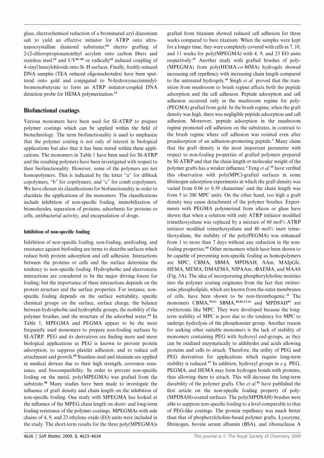
glass, electrochemical reduction of a brominated aryl diazonium
salt to yield an effective initiator for ATRP onto ultra-
nanocrystalline diamond substrates;64 electro grafting of
2-(2-chloropropionate)ethyl acrylate onto carbon fibers and
stainless steel,65 and UV66–68 or radically69 induced coupling of
4-vinyl benzylchloride onto Si–H surfaces. Finally, freshly reduced
DNA samples (TEA reduced oligonucleotides) have been sput-
tered onto gold and conjugated to N-hydroxysuccinimidyl-
bromoisobutyrate to form an ATRP initiator-coupled DNA
detection probe for HEMA polymerization.25
Biofunctional coatings
Various monomers have been used for SI-ATRP to prepare
polymer coatings which can be applied within the field of
biotechnology. The term biofunctionality is used to emphasize
that the polymer coating is not only of interest in biological
applications but also that it has been tested within these appli-
cations. The monomers in Table 1 have been used for SI-ATRP
and the resulting polymers have been investigated with respect to
their biofunctionality. However, some of the polymers are not
homopolymers. This is indicated by the letter ‘‘a’’ for diblock
copolymers, ‘‘b’’ for copolymers, and ‘‘c’’ for comb copolymers.
We have chosen six classifications for biofunctionality in order to
elucidate the applications of the monomers. The classifications
include inhibition of non-specific fouling, immobilization of
biomolecules, separation of proteins, adsorbents for proteins or
cells, antibacterial activity, and encapsulation of drugs.
Inhibition of non-specific fouling
Inhibition of non-specific fouling, non-fouling, antifouling, and
resistance against biofouling are terms to describe surfaces which
reduce both protein adsorption and cell adhesion. Interactions
between the proteins or cells and the surface determine the
tendency to non-specific fouling. Hydrophobic and electrostatic
interactions are considered to be the major driving forces for
fouling; but the importance of these interactions depends on the
protein structure and the surface properties. For instance, non-
specific fouling depends on the surface wettability, specific
chemical groups on the surface, surface charge, the balance
between hydrophobic and hydrophilic groups, the mobility of the
polymer brushes, and the structure of the adsorbed water.82 In
Table 1, MPEGMA and PEGMA appear to be the most
frequently used monomers to prepare non-fouling surfaces by
SI-ATRP. PEG and its derivatives are finding more and more
biological applications as PEG is known to prevent protein
adsorption, to suppress platelet adhesion, and to reduce cell
attachment and growth.68 Stainless steel and titanium are applied
in medical devices due to their high strength, corrosion resis-
tance, and biocompatibility. In order to prevent non-specific
fouling on the metal, poly(MPEGMA) was grafted from the
substrate.48 Many studies have been made to investigate the
influence of graft density and chain length on the inhibition of
non-specific fouling. One study with MPEGMA has looked at
the influence of the MPEG chain length on short- and long-term
fouling resistance of the polymer coatings. MPEGMAs with side
chains of 4, 9, and 23 ethylene oxide (EO) units were included in
the study. The short-term results for the three poly(MPEGMA)s
grafted from titanium showed reduced cell adhesion for three
weeks compared to bare titanium. When the samples were kept
for a longer time, they were completely covered with cells in 7, 10,
and 11 weeks for poly(MPEGMA) with 4, 9, and 23 EO units
respectively.47 Another study with grafted brushes of poly-
(MPEGMA) from poly(HEMA-co-MMA) hydrogels showed
increasing cell repellency with increasing chain length compared
to the untreated hydrogels.16 Singh et al. proved that the tran-
sition from mushroom to brush regime affects both the peptide
adsorption and the cell adhesion. Peptide adsorption and cell
adhesion occurred only in the mushroom regime for poly-
(PEGMA) grafted from gold. In the brush regime, when the graft
density was high, there was negligible peptide adsorption and cell
adhesion. Moreover, peptide adsorption in the mushroom
regime promoted cell adhesion on the substrates, in contrast to
the brush regime where cell adhesion was resisted even after
preadsorption of an adhesion-promoting peptide.3 Many claim
that the graft density is the most important parameter with
respect to non-fouling properties of grafted polymers prepared
by SI-ATRP and that the chain length or molecular weight of the
polymer grafts has a weaker influence.3 Feng et al.39 have verified
this observation with poly(MPC)-grafted surfaces in some
fibrinogen adsorption experiments in which the graft density was
varied from 0.06 to 0.39 chains/nm2 and the chain length was
from 5 to 200 MPC units. On the other hand, too high a graft
density may cause detachment of the polymer brushes. Experi-
ments with PEGMA polymerized from silicon or glass have
shown that when a solution with only ATRP initiator modified
trimethoxysilane was replaced by a mixture of 60 mol% ATRP
initiator modified trimethoxysilane and 40 mol% inert trime-
thoxysilane, the stability of the poly(PEGMA) was enhanced
from 1 to more than 7 days without any reduction in the non-
fouling properties.45 Other monomers which have been shown to
be capable of preventing non-specific fouling as homopolymers
are MPC, CBMA, SBMA, MPDSAH, AAm, MAIpGlc,
HEMA,MEMA, DMAEMA, NIPAAm, tBAEMA, andMAAS
(Fig. 5A). The idea of incorporating phosphorylcholine moieties
into the polymer coating originates from the fact that zwitter-
ionic phospholipids, which are known from the outer membranes
of cells, have been shown to be non-thrombogenic.31 The
monomers CBMA,59,63 SBMA,40,46,57,63 and MPDSAH81 are
zwitterionic like MPC. They were developed because the long-
term stability of MPC is poor due to the tendency for MPC to
undergo hydrolysis of the phosphoester group. Another reason
for seeking other suitable monomers is the lack of stability of
monomers containing PEG with hydroxyl end-groups, as they
can be oxidized enzymatically to aldehydes and acids allowing
proteins and cells to attach. Therefore, the utility of PEG and
PEG derivatives for applications which require long-term
stability is reduced.57 In addition, hydroxyl groups in e.g. PEG,
PEGMA, and HEMA may form hydrogen bonds with proteins,
thus allowing them to attach. This will decrease the long-term
durability of the polymer grafts. Cho et al.81 have published the
first article on the non-specific fouling property of poly-
(MPDSAH)-coated surfaces. The poly(MPDSAH) brushes were
able to suppress non-specific fouling to a level comparable to that
of PEG-like coatings. The protein repellency was much better
than that of phophorylcholine-based polymer grafts. Lysozyme,
fibrinogen, bovine serum albumin (BSA), and ribonuclease A
4626 | Soft Matter, 2009, 5, 4623–4634 This journal is ª The Royal Society of Chemistry 2009

Table1
Survey
ofapplicationsinvolvingbiofunctionalpolymer
coatingsreported
intheliterature
between1997and2009.Biofunctionality:inhibitionofnon-specificfouling(I),im
mobilizationof
biomolecules(II),separationofproteins(III),adsorbents
forproteinsorcells(IV),antibacterialactivity(V
),andencapsulationofdrugs(V
I)
Monomer
Biofunctionality
Substrate
Catalyst:ligand
Solvent
III
III
IVV
VI
AA
65b
14
Cellulose
CuCl:Me 4Cyclam
Water
Stainless
steel
Grubbscatalyst
Toluene
AAm
33,53
70,71
Silica
CuCl:Bipy
DMF
Silicon
CuCl:Bipy,CuCl/CuCl 2:Bipy
DMF,water
tBA
35
Gold
CuBr:PMDETA
Acetone
tBAEMA
65,65b
Stainless
steel
Grubbscatalyst
Toluene
tBMA
44
Silicon
CuBr:PMDETA
Toluene
CBMA
59,63
59
Gold
CuBr:Bipy
Methanol:water
DEAEMA
72b
Gold
CuBr:SP
DMF
DMAEMA
73
73
72b
Gold
CuBr:Bipy,CuBr:SP,CuBr/
CuBr 2:H
MTETA
Water,DMF,acetone
15
Glass/filter
paper
CuBr:Bipy
o-D
CB
19
PP
CuCl/CuCl 2:H
MTETA
Acetone
6PVBC
CuCl/CuBr 2:Bipy
DMF
21
PVDF
CuCl/CuCl 2:Bipy
Water
11
Titanium
CuCl/CuCl 2:PMDETA
74
DMF
74
DMAAm
17
Toyopearl�
CuCl/CuCl 2/Cupowder:H
MTETA
Water
GMA
75b
Fe 3O
4NP
CuBr:PMDETA
Methanol
67a,c
69
67
Silicon
CuCl/CuCl 2:Bipy
DMF:water
GMMA
75b
Fe 3O
4NP
CuBr:PMDETA
Methanol
HEMA
27,28
Glass
CuCl/CuBr 2:Bipy
Water
25,76–78
Gold
CuCl/CuBr 2:Bipy
Water
18,18a
Nylon
CuBr/CuBr 2:H
MTETA
Water
30
Silica
CuBr:Bipy
Methanol
2,33
27,66
2Silicon
CuCl/CuCl 2(Br 2):Bipy
Water
49
Titanium
CuCl/CuCl 2:PMDETA
Water
MAAS
50
50
Titanium
CuCl/CuCl 2:PMDETA
Water
MAIpGlc
41
Silicon
CuBr:Me 6TREN
Veratrole
MEMA
33
Silicon
CuCl/CuCl 2:Bipy
Methanol
MMA
64
Diamond
CuCl/CuCl 2:PMDETA
79
Toluene7
9
36a
Fe 3O
4NP
CuCl:Bipy
DMF
33
Silicon
CuCl/CuCl 2:Bipy
THF
MPC
31,39,44,80
Silicon
CuBr:Bipy
Methanol,methanol:water
MPDSAH
81
Gold
CuBr/CuBr 2:Bipy
Methanol:water
MPEGMA
32
Glass
CuBr:Bipy
Methanol:water
26,55–57,63
60,76,77
72b
Gold
CuBr:SP,CuCl/CuBr 2:Bipy,
CuBr:Bipy
DMF,water,methanol:water
16
Hydrogels
CuBr:Me 6TREN
etc.
Water
8,9
PVDF
CuCl/CuCl 2:Bipy,CuCl:DMDP
Water,NMP
82
Silica
CuCl/CuCl 2:Bipy
Methanol
26,82
37,51b
Silicon
CuCl(Br)/CuCl 2(Br 2):Bipy,
CuBr:PMDETA
Methanol,water,ethanol
32
Siliconoxide
CuBr:Bipy
Methanol:water
48,65b
Stainless
steel
Grubbscatalyst,CuBr:PMDETA
Toluene,
water
47,48
Titanium
CuBr:PMDETA
Water
23
Various
CuBr/CuBr 2:Bipy
Water
This journal is ª The Royal Society of Chemistry 2009 Soft Matter, 2009, 5, 4623–4634 | 4627
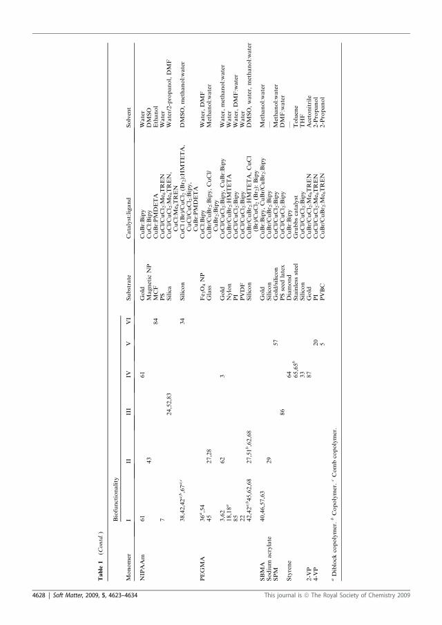
Table
1(C
ontd.)
Monomer
Biofunctionality
Substrate
Catalyst:ligand
Solvent
III
III
IVV
VI
NIPAAm
61
61
Gold
CuBr:Bipy
Water
43
MagneticNP
CuCl:Bipy
DMSO
84
MCF
CuBr:PMDETA
Ethanol
7PS
CuCl/CuCl 2:M
e 6TREN
Water
24,52,83
Silica
CuCl/CuCl 2:M
e 6TREN,
CuCl:Me 6TREN
Water/2-propanol,DMF
38,42,42a,b,67a,c
34
Silicon
CuCl(Br)/CuCl 2(Br 2):HMTETA,
CuCl/CuCl 2:Bipy,
CuBr:PMDETA
DMSO,methanol:water
PEGMA
36a,54
Fe 3O
4NP
CuCl:Bipy
Water,DMF
45
27,28
Glass
CuBr/CuBr 2:Bipy,CuCl/
CuBr 2:Bipy
Methanol:water
3,62
62
3Gold
CuCl/CuCl 2:Bipy,CuBr:Bipy
Water,methanol:water
18,18a
Nylon
CuBr/CuBr 2:H
MTETA
Water
85
PI
CuCl/CuCl 2:Bipy
Water,DMF:water
22
PVDF
CuCl/CuCl 2:Bipy
Water
42,42a,b45,62,68
27,51b,62,68
Silicon
CuBr/CuBr 2:H
MTETA,CuCl
(Br)/CuCl 2(Br 2):Bipy
DMSO,water,methanol:water
SBMA
40,46,57,63
Gold
CuBr:Bipy,CuBr/CuBr 2:Bipy
Methanol:water
Sodium
acrylate
29
Silicon
CuBr/CuBr 2:Bipy
—SPM
57
Gold/silicon
CuCl/CuCl 2:Bipy
Methanol:water
86
PSseed
latex
CuCl/CuCl 2:Bipy
DMF:water
Styrene
64
Diamond
CuBr:Bipy
—65,65b
Stainless
steel
Grubbscatalyst
Toluene
33
Silicon
CuCl/CuCl 2:Bipy
THF
2-V
P87
Gold
CuBr/CuCl 2:M
e 6TREN
Acetonitrile
4-V
P20
PI
CuCl/CuCl 2:M
e 6TREN
2-Propanol
5PVBC
CuBr/CuBr 2:M
e 6TREN
2-Propanol
aDiblock
copolymer.bCopolymer.cCombcopolymer.
4628 | Soft Matter, 2009, 5, 4623–4634 This journal is ª The Royal Society of Chemistry 2009
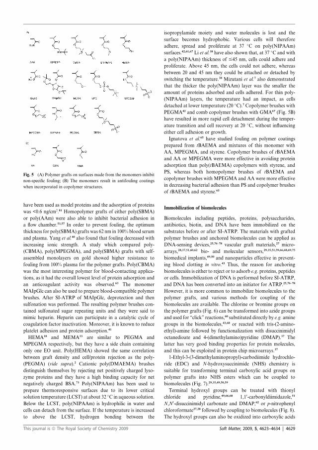
have been used as model proteins and the adsorption of proteins
was <0.6 ng/cm2.81 Homopolymer grafts of either poly(SBMA)
or poly(AAm) were also able to inhibit bacterial adhesion in
a flow chamber.53,57 In order to prevent fouling, the optimum
thickness for poly(SBMA) grafts was 62 nm in 100% blood serum
and plasma. Yang et al.40 also found that fouling decreased with
increasing ionic strength. A study which compared poly-
(CBMA), poly(MPEGMA), and poly(SBMA) grafts with self-
assembled monolayers on gold showed higher resistance to
fouling from 100% plasma for the polymer grafts. Poly(CBMA)
was the most interesting polymer for blood-contacting applica-
tions, as it had the overall lowest level of protein adsorption and
an anticoagulant activity was observed.63 The monomer
MAIpGlc can also be used to prepare blood-compatible polymer
brushes. After SI-ATRP of MAIpGlc, deprotection and then
sulfonation was performed. The resulting polymer brushes con-
tained sulfonated sugar repeating units and they were said to
mimic heparin. Heparin can participate in a catalytic cycle of
coagulation factor inactivation. Moreover, it is known to reduce
platelet adhesion and protein adsorption.41
HEMA18 and MEMA33 are similar to PEGMA and
MPEGMA respectively, but they have a side chain containing
only one EO unit. Poly(HEMA) showed the same correlation
between graft density and cell/protein rejection as the poly-
(PEGMA) (vide supra).2 Cationic poly(DMAEMA) brushes
distinguish themselves by rejecting net positively charged lyso-
zyme proteins and they have a high binding capacity for net
negatively charged BSA.73 Poly(NIPAAm) has been used to
prepare thermoresponsive surfaces due to its lower critical
solution temperature (LCST) at about 32 �C in aqueous solution.
Below the LCST, poly(NIPAAm) is hydrophilic in water and
cells can detach from the surface. If the temperature is increased
to above the LCST, hydrogen bonding between the
isopropylamide moiety and water molecules is lost and the
surface becomes hydrophobic. Various cells will therefore
adhere, spread and proliferate at 37 �C on poly(NIPAAm)
surfaces.42,61,67 Li et al.38 have also shown that, at 37 �C and with
a poly(NIPAAm) thickness of #45 nm, cells could adhere and
proliferate. Above 45 nm, the cells could not adhere, whereas
between 20 and 45 nm they could be attached or detached by
switching the temperature.38 Mizutani et al.7 also demonstrated
that the thicker the poly(NIPAAm) layer was the smaller the
amount of proteins adsorbed and cells adhered. For thin poly-
(NIPAAm) layers, the temperature had an impact, as cells
detached at lower temperature (20 �C).7 Copolymer brushes with
PEGMA42 and comb copolymer brushes with GMA67 (Fig. 5B)
have resulted in more rapid cell detachment during the temper-
ature transition and cell recovery at 20 �C, without influencingeither cell adhesion or growth.
Ignatova et al.65 have studied fouling on polymer coatings
prepared from tBAEMA and mixtures of this monomer with
AA, MPEGMA, and styrene. Copolymer brushes of tBAEMA
and AA or MPEGMA were more effective in avoiding protein
adsorption than poly(tBAEMA) copolymers with styrene, and
PS, whereas both homopolymer brushes of tBAEMA and
copolymer brushes with MPEGMA and AA were more effective
in decreasing bacterial adhesion than PS and copolymer brushes
of tBAEMA and styrene.65
Immobilization of biomolecules
Biomolecules including peptides, proteins, polysaccharides,
antibiotics, biotin, and DNA have been immobilized on the
substrates before or after SI-ATRP. The materials with grafted
polymer brushes and anchored biomolecules can be applied as
DNA-sensing devices,25,76–78 vascular graft materials,27 micro-
arrays,28,37,51,60,62 bio- and molecular sensors,29,35,51,59,66,68,69,75
biomedical implants,49,50 and nanoparticles effective in prevent-
ing blood clotting in vitro.43 Thus, the reason for anchoring
biomolecules is either to reject or to adsorb e.g. proteins, peptides
or cells. Immobilization of DNA is performed before SI-ATRP,
and DNA has been converted into an initiator for ATRP.25,76–78
However, it is more common to immobilize biomolecules to the
polymer grafts, and various methods for coupling of the
biomolecules are available. The chlorine or bromine groups on
the polymer grafts (Fig. 6) can be transformed into azide groups
and used for ‘‘click’’ reactions,60 substituted directly by e.g. amine
groups in the biomolecules,43,68 or reacted with tris-(2-amino-
ethyl)-amine followed by functionalization with disuccinimidyl
octanedioate and 4-(dimethylamino)pyridine (DMAP).37 The
latter has very good binding properties for protein molecules,
and this can be exploited in protein chip microarrays.37
1-Ethyl-3-(3-dimethylaminopropyl)-carbodiimide hydrochlo-
ride (EDC) and N-hydroxysuccinimide (NHS) chemistry is
suitable for transforming terminal carboxylic acid groups on
polymer grafts into NHS esters which can be coupled to
biomolecules (Fig. 7).29,35,49,50,59
Terminal hydroxyl groups can be treated with thionyl
chloride and pyridine,49,66,68 1,10-carbonyldiimidazole,51
N,N0-disuccinimidyl carbonate and DMAP,62 or p-nitrophenyl
chloroformate27,28 followed by coupling to biomolecules (Fig. 8).
The hydroxyl groups can also be oxidized into carboxylic acids
Fig. 5 (A) Polymer grafts on surfaces made from the monomers inhibit
non-specific fouling; (B) The monomers result in antifouling coatings
when incorporated in copolymer structures.
This journal is ª The Royal Society of Chemistry 2009 Soft Matter, 2009, 5, 4623–4634 | 4629
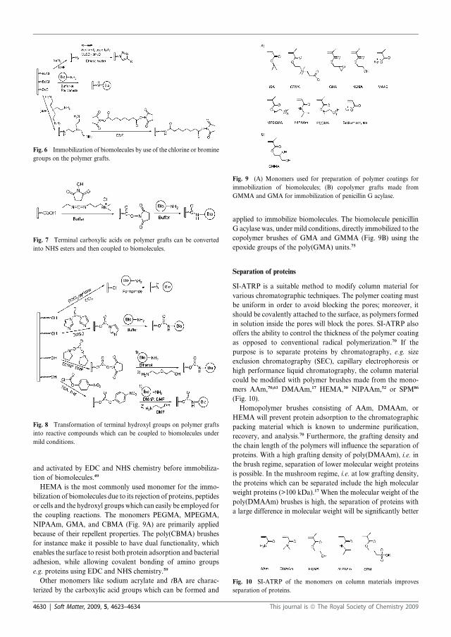
and activated by EDC and NHS chemistry before immobiliza-
tion of biomolecules.49
HEMA is the most commonly used monomer for the immo-
bilization of biomolecules due to its rejection of proteins, peptides
or cells and the hydroxyl groups which can easily be employed for
the coupling reactions. The monomers PEGMA, MPEGMA,
NIPAAm, GMA, and CBMA (Fig. 9A) are primarily applied
because of their repellent properties. The poly(CBMA) brushes
for instance make it possible to have dual functionality, which
enables the surface to resist both protein adsorption and bacterial
adhesion, while allowing covalent bonding of amino groups
e.g. proteins using EDC and NHS chemistry.59
Other monomers like sodium acrylate and tBA are charac-
terized by the carboxylic acid groups which can be formed and
applied to immobilize biomolecules. The biomolecule penicillin
G acylase was, under mild conditions, directly immobilized to the
copolymer brushes of GMA and GMMA (Fig. 9B) using the
epoxide groups of the poly(GMA) units.75
Separation of proteins
SI-ATRP is a suitable method to modify column material for
various chromatographic techniques. The polymer coating must
be uniform in order to avoid blocking the pores; moreover, it
should be covalently attached to the surface, as polymers formed
in solution inside the pores will block the pores. SI-ATRP also
offers the ability to control the thickness of the polymer coating
as opposed to conventional radical polymerization.70 If the
purpose is to separate proteins by chromatography, e.g. size
exclusion chromatography (SEC), capillary electrophoresis or
high performance liquid chromatography, the column material
could be modified with polymer brushes made from the mono-
mers AAm,70,63 DMAAm,17 HEMA,30 NIPAAm,52 or SPM86
(Fig. 10).
Homopolymer brushes consisting of AAm, DMAAm, or
HEMA will prevent protein adsorption to the chromatographic
packing material which is known to undermine purification,
recovery, and analysis.70 Furthermore, the grafting density and
the chain length of the polymers will influence the separation of
proteins. With a high grafting density of poly(DMAAm), i.e. in
the brush regime, separation of lower molecular weight proteins
is possible. In the mushroom regime, i.e. at low grafting density,
the proteins which can be separated include the high molecular
weight proteins (>100 kDa).17 When the molecular weight of the
poly(DMAAm) brushes is high, the separation of proteins with
a large difference in molecular weight will be significantly better
Fig. 6 Immobilization of biomolecules by use of the chlorine or bromine
groups on the polymer grafts.
Fig. 7 Terminal carboxylic acids on polymer grafts can be converted
into NHS esters and then coupled to biomolecules.
Fig. 8 Transformation of terminal hydroxyl groups on polymer grafts
into reactive compounds which can be coupled to biomolecules under
mild conditions.
Fig. 9 (A) Monomers used for preparation of polymer coatings for
immobilization of biomolecules; (B) copolymer grafts made from
GMMA and GMA for immobilization of penicillin G acylase.
Fig. 10 SI-ATRP of the monomers on column materials improves
separation of proteins.
4630 | Soft Matter, 2009, 5, 4623–4634 This journal is ª The Royal Society of Chemistry 2009

than with lower molecular weight brushes.17 Studies with poly-
(NIPAAm) brushes have shown that separation of hydrophilic
substances like proteins or peptides takes place only above the
LCST transition. Therefore, proteins are separated through
hydrophobic interactions whereas lower molecular weight
substances are separated in the SEC mode. Thus, longer reten-
tion times are observed for hydrophobic steroids due to their
longer permeation path through the matrix. For this reason, not
only temperature but also the grafting density of poly(NIPAAm)
is crucial for the elution of steroids due to the interactions
between analytes and brushes and the dehydration of the
poly(NIPAAm) brushes on the densely packed surface.24,52,83
Adsorbents for proteins or cells
Adsorbents for proteins or cells, which are known as non-
specific fouling, can be prepared for three purposes. The first is
to apply the polymer brushes in adsorption studies or applica-
tions in which adsorption is needed. The second is to obtain
polymer brushes which either adsorb or reject proteins or cells
depending on the grafting density or the charge of the adsor-
bate. Thirdly, some polymer brushes are used for comparison,
because they are known to adsorb proteins or cells. Polymer
brushes prepared by SI-ATRP of the monomers AA,14
styrene,33,64 and MMA33,64 (Fig. 11) can be used as adsorbents
for proteins, whereas poly(NIPAAm) brushes show promising
results for cell cultivation of fibroblasts at 40 �C (above the
LCST).61
SI-ATRP of 2-VP resulted in a uniform polymer surface which
made it suitable for adsorption studies by surface plasmon
resonance.87 Poly(PEGMA) and poly(HEMA) brushes will, in
the mushroom regime (low grafting density), adsorb peptides
and reject cells.2,3 However, the adsorption of proteins to
a surface with poly(DMAEMA) depends on the charge of the
proteins, as poly(DMAEMA) brushes demonstrate high binding
capacity for net negatively charged proteins.73 Homopolymer
brushes consisting of GMA67 and styrene65 or copolymers with
styrene65 were used for comparison, as they were good adsor-
bents for cells. Moreover, a poly(tBMA) coating was chosen as
a positive control since a larger amount of protein will adsorb to
the brushes than to poly(MPC).44
Antibacterial activity
The term antibacterial is defined as being able to kill or reduce
the harmful effect of bacteria (Cambridge Advanced Learner’s
Dictionary). Therefore, antibacterial polymer coatings should
not only reject bacteria, they should also interfere with the
growth and reproduction of bacteria. SI-ATRP of DMAEMA
(Fig. 12) followed by quaternization of the tertiary amine
groups is the most prevalent ‘‘grafting-from’’ method that
leads to antibacterial polymer coatings. DMAEMA has been
polymerized from various substrates, such as filter paper,15 PP,19
PVBC,6 PVDF,21 and titanium.49 Quaternized poly(DMAEMA)
coatings on filter paper and PVBC were able to kill 109 bacteria
on a 6.25 cm2 piece and 105 on a 1.4 cm2 surface respectively.6,15
The study with PP substrates showed that quaternized poly-
(DMAEMA) brushes with Mn > 10 000 had almost 100% killing
efficiency whereas shorter chains had a lower antibacterial
activity (85% for Mn ¼ 1500).19 The interactions between
quaternary amine groups and the bacteria are believed not only
to kill the bacteria but also to break the bacterial body into
fragments.15,21,49
The monomer 4-VP can also be applied to prepare quaternized
polymer brushes which are antibacterial. Quaternized poly(4-VP)
grafted fromPVBCwasable to terminate the sameamount (105) of
bacteria on 1.4 cm2 surface as the quaternized poly(DMAEMA)
brushes.5 SI-ATRP of 4-VP from PI confirmed the observations
for DMAEMA, as better antibacterial properties were obtained if
longer polymerization times were used because this gave longer
chains and more pyridinium groups.20 Another approach to
obtain antibacterial coatings has been used with poly(SPM)
brushes. The poly(SPM) brushes were loaded with silver, and like
the quaternized polymer brushes they were found to be antibac-
terial towards both gram negative and gram positive bacteria.57
Encapsulation of drugs
Stimuli-responsive polymers will be suitable for encapsulation of
a drug as well as for load and release of the drug. The polymer
brushes could be sensitive to external factors such as tempera-
ture, pH, or salt concentration.84 The LCST of NIPAAm
(Fig. 13A) has already been mentioned for the rejection of cells,
and the hydrophobic–hydrophilic transition at 32 �C also makes
it useful for the controlled release of a drug. Poly(NIPAAm)
brushes grafted from surfaces have in two different studies been
demonstrated to be suitable for encapsulation of a drug. One
example is a mesostructured cellular foam with poly(NIPAAm)
brushes which showed a storage capacity of 58 wt% ibuprofen.84
The other example is the uptake of aspirin by poly(NIPAAm)
grafted from silicon above the LCST and released below the
LCST. This temperature-dependent loading and release of a drug
was achieved with low graft densities for poly(NIPAAm).34
Finally, pH-responsive capsules can be made from cross-
linkable copolymer brushes, which have been grafted from gold
nanocrystals. The gold cores are etched out after crosslinking the
Fig. 11 Non-specific fouling has been observed on surfaces with poly-
mer grafts prepared from the monomers.
Fig. 12 SI-ATRP of the monomers followed by quaternization or
loading with silver results in antibacterial surfaces.
This journal is ª The Royal Society of Chemistry 2009 Soft Matter, 2009, 5, 4623–4634 | 4631
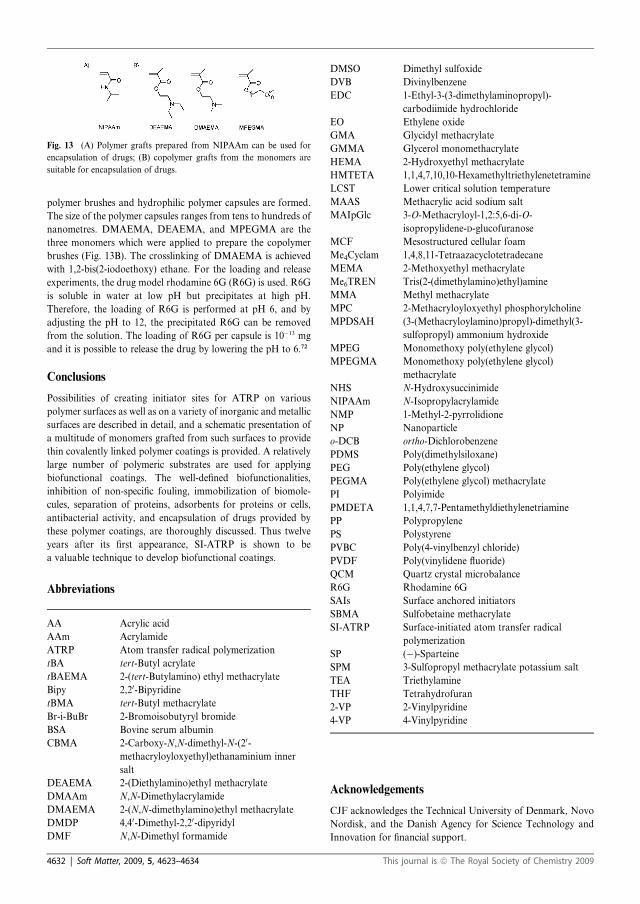
polymer brushes and hydrophilic polymer capsules are formed.
The size of the polymer capsules ranges from tens to hundreds of
nanometres. DMAEMA, DEAEMA, and MPEGMA are the
three monomers which were applied to prepare the copolymer
brushes (Fig. 13B). The crosslinking of DMAEMA is achieved
with 1,2-bis(2-iodoethoxy) ethane. For the loading and release
experiments, the drug model rhodamine 6G (R6G) is used. R6G
is soluble in water at low pH but precipitates at high pH.
Therefore, the loading of R6G is performed at pH 6, and by
adjusting the pH to 12, the precipitated R6G can be removed
from the solution. The loading of R6G per capsule is 10�13 mg
and it is possible to release the drug by lowering the pH to 6.72
Conclusions
Possibilities of creating initiator sites for ATRP on various
polymer surfaces as well as on a variety of inorganic and metallic
surfaces are described in detail, and a schematic presentation of
a multitude of monomers grafted from such surfaces to provide
thin covalently linked polymer coatings is provided. A relatively
large number of polymeric substrates are used for applying
biofunctional coatings. The well-defined biofunctionalities,
inhibition of non-specific fouling, immobilization of biomole-
cules, separation of proteins, adsorbents for proteins or cells,
antibacterial activity, and encapsulation of drugs provided by
these polymer coatings, are thoroughly discussed. Thus twelve
years after its first appearance, SI-ATRP is shown to be
a valuable technique to develop biofunctional coatings.
Abbreviations
AA Acrylic acid
AAm Acrylamide
ATRP Atom transfer radical polymerization
tBA tert-Butyl acrylate
tBAEMA 2-(tert-Butylamino) ethyl methacrylate
Bipy 2,20-BipyridinetBMA tert-Butyl methacrylate
Br-i-BuBr 2-Bromoisobutyryl bromide
BSA Bovine serum albumin
CBMA 2-Carboxy-N,N-dimethyl-N-(20-methacryloyloxyethyl)ethanaminium inner
salt
DEAEMA 2-(Diethylamino)ethyl methacrylate
DMAAm N,N-Dimethylacrylamide
DMAEMA 2-(N,N-dimethylamino)ethyl methacrylate
DMDP 4,40-Dimethyl-2,20-dipyridylDMF N,N-Dimethyl formamide
DMSO Dimethyl sulfoxide
DVB Divinylbenzene
EDC 1-Ethyl-3-(3-dimethylaminopropyl)-
carbodiimide hydrochloride
EO Ethylene oxide
GMA Glycidyl methacrylate
GMMA Glycerol monomethacrylate
HEMA 2-Hydroxyethyl methacrylate
HMTETA 1,1,4,7,10,10-Hexamethyltriethylenetetramine
LCST Lower critical solution temperature
MAAS Methacrylic acid sodium salt
MAIpGlc 3-O-Methacryloyl-1,2:5,6-di-O-
isopropylidene-D-glucofuranose
MCF Mesostructured cellular foam
Me4Cyclam 1,4,8,11-Tetraazacyclotetradecane
MEMA 2-Methoxyethyl methacrylate
Me6TREN Tris(2-(dimethylamino)ethyl)amine
MMA Methyl methacrylate
MPC 2-Methacryloyloxyethyl phosphorylcholine
MPDSAH (3-(Methacryloylamino)propyl)-dimethyl(3-
sulfopropyl) ammonium hydroxide
MPEG Monomethoxy poly(ethylene glycol)
MPEGMA Monomethoxy poly(ethylene glycol)
methacrylate
NHS N-Hydroxysuccinimide
NIPAAm N-Isopropylacrylamide
NMP 1-Methyl-2-pyrrolidione
NP Nanoparticle
o-DCB ortho-Dichlorobenzene
PDMS Poly(dimethylsiloxane)
PEG Poly(ethylene glycol)
PEGMA Poly(ethylene glycol) methacrylate
PI Polyimide
PMDETA 1,1,4,7,7-Pentamethyldiethylenetriamine
PP Polypropylene
PS Polystyrene
PVBC Poly(4-vinylbenzyl chloride)
PVDF Poly(vinylidene fluoride)
QCM Quartz crystal microbalance
R6G Rhodamine 6G
SAIs Surface anchored initiators
SBMA Sulfobetaine methacrylate
SI-ATRP Surface-initiated atom transfer radical
polymerization
SP (�)-Sparteine
SPM 3-Sulfopropyl methacrylate potassium salt
TEA Triethylamine
THF Tetrahydrofuran
2-VP 2-Vinylpyridine
4-VP 4-Vinylpyridine
Acknowledgements
CJF acknowledges the Technical University of Denmark, Novo
Nordisk, and the Danish Agency for Science Technology and
Innovation for financial support.
Fig. 13 (A) Polymer grafts prepared from NIPAAm can be used for
encapsulation of drugs; (B) copolymer grafts from the monomers are
suitable for encapsulation of drugs.
4632 | Soft Matter, 2009, 5, 4623–4634 This journal is ª The Royal Society of Chemistry 2009

References
1 (a) W. A. Braunecker and K. Matyjaszewski, Prog. Polym. Sci., 2007,32, 93–146; (b) N. M. L. Hansen, K. Jankova and S. Hvilsted, Eur.Polym. J., 2007, 43, 255–293; (c) J. A. Opsteen and J. C. M. vanHest, in Macromolecular Engineering, ed. K. Matyjaszewski,Y. Gnanou and L. Leibler, Wiley-VCH, Weinheim, 2007, vol. IV,(ch. 16.4), pp. 2662–2671; (d) N. V. Tsarevsky andK. Matyjaszewski, Chem. Rev., 2007, 107, 2270–2299.
2 Y. Mei, T. Wu, C. Xu, K. J. Langenbach, J. T. Elliott, B. D. Vogt,K. L. Beers, E. J. Amis and N. R. Washburn, Langmuir, 2005, 21,12309–12314.
3 N. Singh, X. F. Cui, T. Boland and S. M. Husson, Biomaterials, 2007,28, 763–771.
4 C. P. Chen, B. T. Ko, S. L. Lin, M. Y. Hsu and C. Ting, Polymer,2006, 47, 6630–6635.
5 Z. P. Cheng, X. L. Zhu, Z. L. Shi, K. G. Neoh and E. T. Kang, Surf.Rev. Lett., 2006, 13, 313–318.
6 Z. P. Cheng, X. L. Zhu, Z. L. Shi, K. G. Neoh and E. T. Kang, Ind.Eng. Chem. Res., 2005, 44, 7098–7104.
7 A. Mizutani, A. Kikuchi, M. Yamato, H. Kanazawa and T. Okano,Biomaterials, 2008, 29, 2073–2081.
8 Y. W. Chen, D. M. Liu, Q. L. Deng, X. H. He and X. F. Wang,J. Polym. Sci., Part A: Polym. Chem., 2006, 44, 3434–3443.
9 J. F. Hester, P. Banerjee, Y. Y. Won, A. Akthakul, M. H. Acar andA. M. Mayes, Macromolecules, 2002, 35, 7652–7661.
10 P. Liu, E-Polymers, 2007, 062.11 B. Radhakrishnan, R. Ranjan and W. J. Brittain, Soft Matter, 2006,
2, 386–396.12 C. M. Homenick, G. Lawson and A. Adronov, Polym. Rev., 2007, 47,
265–290.13 D. Bontempo, N. Tirelli, K. Feldman, G. Masci, V. Crescenzi and
J. A. Hubbell, Adv. Mater., 2002, 14, 1239–1241.14 N. Singh, J. Wang, M. Ulbricht, S. R. Wickramasinghe and
S. M. Husson, J. Membr. Sci., 2008, 309, 64–72.15 S. B. Lee, R. R. Koepsel, S. W. Morley, K. Matyjaszewski, Y. J. Sun
and A. J. Russell, Biomacromolecules, 2004, 5, 877–882.16 D. Bozukova, C. Pagnoulle, M. C. Pauw-Gillet, N. Ruth, R. Jerome
and C. Jerome, Langmuir, 2008, 24, 6649–6658.17 B. R. Coad, B. M. Steels, J. N. Kizhakkedathu, D. E. Brooks and
C. A. Haynes, Biotechnol. Bioeng., 2007, 97, 574–587.18 F. J. Xu, J. P. Zhao, E. T. Kang, K. G. Neoh and J. Li, Langmuir,
2007, 23, 8585–8592.19 J. Y. Huang, H. Murata, R. R. Koepsel, A. J. Russell and
K. Matyjaszewski, Biomacromolecules, 2007, 8, 1396–1399.20 L. Li, Z. J. Ke, G. P. Yan and J. Y. Wu, Polym. Int., 2008, 57,
1275–1280.21 G. Q. Zhai, Z. L. Shi, E. T. Kang and K. G. Neoh,Macromol. Biosci.,
2005, 5, 974–982.22 G. Q. Zhai, E. T. Kang and K. G. Neoh, Macromolecules, 2004, 37,
7240–7249.23 X.W. Jiang, H. Y. Chen, G. Galvan,M. Yoshida and J. Lahann,Adv.
Funct. Mater., 2008, 18, 27–35.24 N. Idota, A. Kikuchi, J. Kobayashi, Y. Akiyama and T. Okano,
Langmuir, 2006, 22, 425–430.25 G. O. Okelo and L. He, Biosens. Bioelectron., 2007, 23, 588–592.26 A. A. Brown, N. S. Khan, L. Steinbock and W. T. S. Huck, Eur.
Polym. J., 2005, 41, 1757–1765.27 S. Tugulu, P. Silacci, N. Stergiopulos and H. A. Klok, Biomaterials,
2007, 28, 2536–2546.28 S. Tugulu, A. Arnold, I. Sielaff, K. Johnsson and H. A. Klok,
Biomacromolecules, 2005, 6, 1602–1607.29 R. Dong, S. Krishnan, B. A. Baird, M. Lindau and C. K. Ober,
Biomacromolecules, 2007, 8, 3082–3092.30 C. Yoshikawa, A. Goto, Y. Tsujii, N. Ishizuka, K. Nakanishi and
T. Fukuda, J. Polym. Sci., Part A: Polym. Chem., 2007, 45, 4795–4803.
31 W. Feng, S. P. Zhu, K. Ishihara and J. L. Brash, Langmuir, 2005, 21,5980–5987.
32 H. W. Ma, D. J. Li, X. Sheng, B. Zhao and A. Chilkoti, Langmuir,2006, 22, 3751–3756.
33 T. Tsukagoshi, Y. Kondo and N. Yoshino,Colloids Surf., B, 2007, 54,101–107.
34 T. Tsukagoshi, Y. Kondo and N. Yoshino,Colloids Surf., B, 2007, 57,219–225.
35 S. Kurosawa, H. Aizawa, Z. A. Talib, B. Atthoff and J. Hilborn,Biosens. Bioelectron., 2004, 20, 1165–1176.
36 Y. Zhou, S. X. Wang, B. J. Ding and Z. M. Yang, Chem. Eng. J.,2008, 138, 578–585.
37 Y. Yao, Y. Z. Ma, M. Qin, X. J. Ma, C. Wang and X. Z. Feng,Colloids Surf., B, 2008, 66, 233–239.
38 L. H. Li, Y. Zhu, B. Li and C. Y. Gao, Langmuir, 2008, 24,13632–13639.
39 W. Feng, J. L. Brash and S. P. Zhu, Biomaterials, 2006, 27,847–855.
40 W. Yang, S. F. Chen, G. Cheng, H. Vaisocherova, H. Xue, W. Li,J. L. Zhang and S. Y. Jiang, Langmuir, 2008, 24, 9211–9214.
41 N. Ayres, D. J. Holt, C. F. Jones, L. E. Corum and D. W. Grainger,J. Polym. Sci., Part A: Polym. Chem., 2008, 46, 7713–7724.
42 F. J. Xu, S. P. Zhong, L. Y. L. Yung, E. T. Kang and K. G. Neoh,Biomacromolecules, 2004, 5, 2392–2403.
43 S. C. Wuang, K. G. Neoh, E. T. Kang, D. W. Pack andD. E. Leckband, Adv. Funct. Mater., 2006, 16, 1723–1730.
44 V. P. Hoven, M. Srinanthakul, Y. Iwasaki, R. Iwata andS. Kiatkamjornwong, J. Colloid Interface Sci., 2007, 314, 446–459.
45 S. Tugulu and H. A. Klok, Biomacromolecules, 2008, 9, 906–912.46 G. Z. Li, H. Xue, G. Cheng, S. F. Chen, F. B. Zhang and S. Y. Jiang,
J. Phys. Chem. B, 2008, 112, 15269–15274.47 X.W. Fan, L. J. Lin and P. B.Messersmith, Biomacromolecules, 2006,
7, 2443–2448.48 X. W. Fan, L. J. Lin, J. L. Dalsin and P. B. Messersmith, J. Am.
Chem. Soc., 2005, 127, 15843–15847.49 F. Zhang, Z. L. Shi, P. H. Chua, E. T. Kang and K. G. Neoh, Ind.
Eng. Chem. Res., 2007, 46, 9077–9086.50 F. Zhang, Z. B. Zhang, X. L. Zhu, E. T. Kang and K. G. Neoh,
Biomaterials, 2008, 29, 4751–4759.51 F. J. Xu, H. Z. Li, J. Li, Y. H. E. Teo, C. X. Zhu, E. T. Kang and
K. G. Neoh, Biosens. Bioelectron., 2008, 24, 773–780.52 K. Nagase, J. Kobayashi, A. Kikuchi, Y. Akiyama, H. Kanazawa and
T. Okano, Langmuir, 2007, 23, 9409–9415.53 I. Cringus-Fundeanu, J. Luijten, H. C. van der Mei, H. J. Busscher
and A. J. Schouten, Langmuir, 2007, 23, 5120–5126.54 F. X. Hu, K. G. Neoh, L. Cen and E. T. Kang, Biomacromolecules,
2006, 7, 809–816.55 H.W.Ma, M.Wells, T. P. Beebe and A. Chilkoti, Adv. Funct. Mater.,
2006, 16, 640–648.56 H. W. Ma, J. H. Hyun, P. Stiller and A. Chilkoti, Adv. Mater., 2004,
16, 338–341.57 G. Cheng, Z. Zhang, S. F. Chen, J. D. Bryers and S. Y. Jiang,
Biomaterials, 2007, 28, 4192–4199.58 M. Ramstedt, N. Cheng, O. Azzaroni, D. Mossialos, H. J. Mathieu
and W. T. S. Huck, Langmuir, 2007, 23, 3314–3321.59 Z. Zhang, S. F. Chen and S. Y. Jiang, Biomacromolecules, 2006, 7,
3311–3315.60 B. S. Lee, J. K. Lee, W. J. Kim, Y. H. Jung, S. J. Sim, J. Lee and
I. S. Choi, Biomacromolecules, 2007, 8, 744–749.61 D. J. Kim, B. Kong, Y. H. Jung, K. S. Kim, W. J. Kim, K. B. Lee,
S. M. Kang, S. Jeon and I. S. Choi, Bull. Korean Chem. Soc., 2004,25, 1629–1630.
62 B. S. Lee, Y. S. Chi, K. B. Lee, Y. G. Kim and I. S. Choi,Biomacromolecules, 2007, 8, 3922–3929.
63 Z. Zhang, M. Zhang, S. F. Chen, T. A. Horbetta, B. D. Ratner andS. Y. Jiang, Biomaterials, 2008, 29, 4285–4291.
64 T. Matrab, M. M. Chehimi, J. P. Boudou, F. Benedic, J. Wang,N. N. Naguib and J. A. Carlisle, Diamond Relat. Mater., 2006, 15,639–644.
65 M. Ignatova, S. Voccia, B. Gilbert, N. Markova, D. Cossement,R. Gouttebaron, R. Jerome and C. Jerome, Langmuir, 2006, 22,255–262.
66 F. J. Xu, S. P. Zhong, L. Y. L. Yung, Y. W. Tong, E. T. Kang andK. G. Neoh, Tissue Eng., 2005, 11, 1736–1748.
67 F. J. Xu, S. P. Zhong, L. Y. L. Yung, Y. W. Tong, E. T. Kang andK. G. Neoh, Biomaterials, 2006, 27, 1236–1245.
68 F. J. Xu, Y. L. Li, E. T. Kang and K. G. Neoh, Biomacromolecules,2005, 6, 1759–1768.
69 F. J. Xu, Q. J. Cai, Y. L. Li, E. T. Kang and K. G. Neoh,Biomacromolecules, 2005, 6, 1012–1020.
70 X. Y. Huang, L. J. Doneski and M. J. Wirth, ChemTech, 1998, 28,19–25.
71 X. Y. Huang and M. J. Wirth, Anal. Chem., 1997, 69, 4577–4580.
This journal is ª The Royal Society of Chemistry 2009 Soft Matter, 2009, 5, 4623–4634 | 4633
72 H. W. Duan, M. Kuang, G. Zhang, D. Y. Wang, D. G. Kurth andH. Mohwald, Langmuir, 2005, 21, 11495–11499.
73 A. Kusumo, L. Bombalski, Q. Lin, K.Matyjaszewski, J. W. Schneiderand R. D. Tilton, Langmuir, 2007, 23, 4448–4454.
74 F. Zhang, F. J. Xu, E. T. Kang andK. G. Neoh, Ind. Eng. Chem. Res.,2006, 45, 3067–3073.
75 J. S. Huang, X. T. Li, Y. H. Zheng, Y. Zhang, R. Y. Zhao, X. C. Gaoand H. S. Yan, Macromol. Biosci., 2008, 8, 508–515.
76 X. H. Lou and L. He, Langmuir, 2006, 22, 2640–2646.77 X. H. Lou, C. Y. Wang and L. He, Biomacromolecules, 2007, 8,
1385–1390.78 X. H. Lou and L. He, Sens. Actuators, B, 2008, 129, 225–230.79 T. Matrab, M. M. Chehimi, C. Perruchot, A. Adenier, A. Guillez,
M. Save, B. Charleux, E. Cabet-Deliry and J. Pinson, Langmuir,2005, 21, 4686–4694.
80 R. Iwata, P. Suk-In, V. P. Hoven, A. Takahara, K. Akiyoshi andY. Iwasaki, Biomacromolecules, 2004, 5, 2308–2314.
81 W. K. Cho, B. Y. Kong and I. S. Choi, Langmuir, 2007, 23, 5678–5682.82 T. Tsukagoshi, Y. Kondo and N. Yoshino,Colloids Surf., B, 2007, 54,
94–100.83 K. Nagase, J. Kobayashi, A. I. Kikuchi, Y. Akiyama, H. Kanazawa
and T. Okano, Langmuir, 2008, 24, 511–517.84 Z. Y. Zhou, S. M. Zhu and D. Zhang, J. Mater. Chem., 2007, 17,
2428–2433.85 L. Li, G. P. Yan, J. Y. Wu, X. H. Yu and Q. Z. Guo, J. Macromol.
Sci., Part A: Pure Appl. Chem., 2008, 45, 828–832.86 E. Unsal, B. Elmas, B. Caglayan, M. Tuncel, S. Patir and A. Tuncel,
Anal. Chem., 2006, 78, 5868–5875.87 X. Li, X. L. Wei and S. M. Husson, Biomacromolecules, 2004, 5,
869–876.
4634 | Soft Matter, 2009, 5, 4623–4634 This journal is ª The Royal Society of Chemistry 2009
B
C.J. Fristrup, K. Jankova, and S. Hvilsted, Hydrophilization of poly(ether ether ketone) films by surface-initiated atom transfer radical polymerization, Polym. Chem., 1 (2010) 1696-1701.
© 2010 The Royal Society of Chemistry
Reproduced by permission of The Royal Society of Chemistry
Link to the article on the Royal Society of Chemistry’s website: http://pubs.rsc.org/en/Content/ArticleLanding/2010/PY/C0PY00142B


Hydrophilization of poly(ether ether ketone) films by surface-initiated atomtransfer radical polymerization
Charlotte Juel Fristrup, Katja Jankova and Søren Hvilsted*
Received 4th May 2010, Accepted 21st August 2010
DOI: 10.1039/c0py00142b
Surface-Initiated Atom Transfer Radical Polymerization (SI-ATRP) has been exploited to
hydrophilize PEEK. The ketone groups on the PEEK surface were reduced to hydroxyl groups which
were converted to bromoisobutyrate initiating sites for SI-ATRP. The modification steps were followed
by contact angle measurements and XPS. Moreover, ATR FTIR has been used to confirm the
formation of initiating groups. Grafting of PEGMA from PEEK was performed in aqueous solution.
The presence of the PPEGMA grafts on PEEK was revealed by the thermograms from TGA whereas
investigations with AFM rejected changes in the surface topography. Two possible applications arose
from the hydrophilization of PEEK, metal deposition and protein repellency. The performed
modification allowed for successful electroless deposition and good adhesion of nickel as well as
copper.
Introduction
Poly(ether ether ketone) (PEEK) can replace aluminium and
other metals in medical, aerospace, electronics, and automotive
applications. Surface modification of PEEK will increase the
applicability of the material considerably. For the pharmaceu-
tical industry non-fouling surfaces are desired whereas in other
fields the demand for metallization is continuously increasing.
In order to obtain good adhesion between metals and the
polymer surfaces strong bonds are needed e.g. charge transfer at
the polymer–metal interface. The most appropriate way to form
a metal–polymer complex is a carboxyl containing polymer
surface.1 Electroless metallisation of polymers is performed in
aqueous solutions of the metal salts, containing numerous
additives. Many factors will contribute to the adhesion of metals
to polymers e.g. polymers with higher surface energy can easier
be metallised. Conventionally, polymer surfaces are etched with
chromic acid prior to electroless metal deposition. The etching
results in hydrophilization of the polymer surface and some
roughness is also introduced, which will support the adhesion of
the metal layer to the polymer. Several steps are needed before
the deposition of the metal e.g. exposure to a catalyst for the
reduction of the metal ions. The reduction is performed to ensure
that the metal is deposited on the surface in question and not on
the walls of the metallisation bath or any other places. Palladium
particles show the desired catalytic activity and they can be
applied in two different ways which are acceptable for almost all
polymers. In the cheapest and most commonmethod Pd particles
are mounted on the chromic acid pretreated polymer surface by
reduction of colloid Pd. The other method is more exclusive and
involves premixed palladium in the polymer. After reduction the
metal (Cu, Ni, Au, etc.) sticks better to the Pd particles.2
Attempts to avoid treatment with chromic acid mainly rely on
substitution with other acids, their mixtures with various organic
or inorganic compounds, as well as laser treatment and plasma
reactive ion etching.3 Therefore, a new method is presented here
to hydrophilize PEEK avoiding hazardous chromic acid and its
attendant effects.
During the last 30 years PEEK has been known for its bio-
logical applications which require surface modification to change
the hydrophobicity of the material. Techniques like plasma
treatment or deposition (mainly plasma spraying of Ti and/or
thermal plasma coating of hydroxyapatite) as well as wet
chemistry4–6 are commonly used.7 The most powerful method is
coating of the hydrophobic PEEK with a hydrophilic polymer.
In that way, an entire new surface layer is added to the substrate.
The method can be divided into ‘‘grafting to’’ or ‘‘grafting from’’.
Where ‘‘grafting to’’ a polymer surface requires both an
anchoring group on the surface as well as a reactive group on the
incoming polymer, in addition to an effective coupling mecha-
nism. Steric hindrance or shielding from the first reacted poly-
mers onto a surface often prevents subsequent polymer grafting
and leads to a low surface coverage. ‘‘Grafting from’’ a surface
involves graft polymerization which is often accomplished by the
use of electrons, UV or plasma treatment of the surface followed
by radical polymerization of various monomers. In general,
conventional radical polymerization will result in poor control of
the new surface layer in terms of chemical functionality and
morphology. Controlled radical polymerization techniques,
especially ATRP,8 provide the best control, where ‘‘control’’
means the ability to shape the polymer architecture and to design
linear, block, graft, star or dendritic forms in a predictable
manner including total control over the chain length (molecular
weight). In principle, the concept of grafting from a polymer also
allows an initiator gradient, enabling a variation in the grafting
density. ATRP normally also offers the possibility to select the
most convenient and appropriate initiator for the monomer in
question. However, in ‘‘grafting from’’ a polymer surface by SI-
ATRP the largest challenge is often to generate surface anchored
initiating sites.9 PEEK has ketone groups which after reduction
can be utilized for anchoring of initiating groups for ATRP.10
Danish Polymer Centre, Department of Chemical and BiochemicalEngineering, Technical University of Denmark, Building 227, DK-2800Kgs. Lyngby, Denmark. E-mail: [email protected]; Fax: +45 4588 2161;Tel: +45 4525 2965
1696 | Polym. Chem., 2010, 1, 1696–1701 This journal is ª The Royal Society of Chemistry 2010
PAPER www.rsc.org/polymers | Polymer Chemistry
Down
loade
d on 3
0 Nov
embe
r 201
0Pu
blish
ed on
13 S
eptem
ber 2
010 o
n http
://pu
bs.rs
c.org
| doi:
10.10
39/C
0PY0
0142
BView Online

Therefore, Surface-Initiated Atom Transfer Radical Polymeri-
zation (SI-ATRP) has been selected as the way to covalently graft
hydrophilic polymer chains from the PEEK surface. Recently,
SI-ATRP was applied to prepare conductive cotton yarns by
grafting of poly(2-(methacryloyloxy)ethyl trimethylammonium
chloride (PMETAC), followed by ion exchange with
(NH4)2PdCl4.11 The palladium moieties are known to act as
effective catalyst sites for the deposition of metals.12 The
hydrophilic polymer grafts in this work were prepared from
poly(ethylene glycol)methacrylate (PEGMA)13 as coatings of
poly(ethylene glycol) (PEG) are known to be compatible with
proteins due to their water solubility and hydrophilicity. The
PEG surfaces are in a liquid-like state with polymer chains
showing high flexibility or mobility (increasing mobility with
chain length up to 100).14 Steric stabilization and chain mobility
play important roles in inhibition of non-specific fouling on PEG
surfaces. The PEG molecules have a large excluded volume in
water which makes them very effective for the steric repulsion.
Additionally, the high surface mobility of PEG chains prevents
protein adsorption as the contact time is shortened.14,15 The size
of the proteins relative to the distance between the PEG chains is
also important for the efficiency of the coatings to inhibit
fouling.16
In this work the surface of PEEK is functionalized by covalent
bonding of hydrophilic polymer brushes of PEGMA from
initiator-modified PEEK using SI-ATRP. Surface reduction of
PEEK to form hydroxyl groups was performed prior to the
attachment of 2-bromoisobutyrate initiating groups. Each
modification step of PEEK as well as the polymer grafting was
followed and confirmed by ATR FTIR, water contact angle
(WCA) measurements, and Thermal Gravimetric Analysis
(TGA). The surface topography was evaluated by Atomic Force
Microscopy (AFM). X-Ray Photoelectron Spectroscopy (XPS)
has been used to investigate the degree of functionalization.
Experimental
Materials and methods
Acetone (Riedel-de Ha€en) was distilled and stored over molec-
ular sieves. Dimethylsulfoxide (DMSO, Fluka) was distilled over
calcium hydride under reduced pressure and stored over molec-
ular sieves. Tetrahydrofuran (THF, Sigma-Aldrich) and trie-
thylamine (TEA, Riedel-de Ha€en) were distilled over calcium
hydride. 2,20-Bipyridine (Bipy, 99%), 2-bromoisobutyrylbromide
(Br-iBuBr, 98%), copper chloride (CuCl, 99%), 4-dimethylami-
nopyridine (DMAP, 99%), methanol (analytical grade), poly-
(ethylene glycol)methacrylate (PEGMA, Mn z360), sodium
chloride (NaCl), and tin(II) chloride dihydrate (SnCl2$2H2O,
98%) were used as supplied by Sigma-Aldrich. Cataposit 958,
ethanol (99.9% vol, Kemetyl), hydrochloric acid (HCl), sodium
borohydride (NaBH4, $96%, Fluka), and ultrapure water were
used without further purification. A sheet of 1.4 m2 of APTIV
1000-750 fromMape Plastics was cut into smaller pieces. APTIV
1000-750 are calendared films made of poly(ether ether ketone)
(PEEK). The thickness of the films was 750 mm.
Attenuated Total Reflectance (ATR) Fourier Transform
Infrared (FTIR) spectra were obtained using a Spectrum One
spectrometer from Perkin Elmer which was equipped with
a universal ATR sample accessory. WCA measurements were
made on an OCA20 Contact Angle System from Dataphysics
with a temperature controller. The temperature was set to 25 �C.The dynamic method called ‘‘sessile drop (needle in)’’ was used
and the WCAs were computed using ‘‘Ellipse Fitting’’. The
measurements were made on three drops of deionized water at
different spots and three values for both the advancing and
receding angles were used to determine the average value.
Thermal degradation was investigated by TGA performed with
a TGA Q500 from TA Instruments recording the total weight
loss of approx. 10–12 mg samples from room temperature to
800 �C at a rate of 10 �Cmin�1 in a nitrogen flow of 90 mLmin�1.
The atomic force microscope was a Nanosurf EasyScan 2 system
which could make nanometre scale resolution measurements of
topography. The maximum scan range was 110 mm and the
maximum Z-range was 22 mm, with a resolution of approxi-
mately 2 nm in the XY directions and 0.3 nm in the Z direction.
The advantage of this system was that the sample size could be
unlimited. XPS analysis was performed on a Thermo Fisher
Scientific K Alpha using monochromatized aluminium KR
radiation in a 400 mm spot on the sample. Survey and high-
resolution spectra were acquired and analyzed using the manu-
facturer’s Advantage software package.
The samples were pretreated before metallisation in electroless
nickel and copper baths. Pretreatment of the samples involved
immersion in an activation solution at room temperature for 3
min. The activation solution had the following composition (per
litre): 180 g NaCl, 120 mL concentrated HCl, 1 g SnCl2$2H2O,
and 20 mL Cataposit 958 (colloidal tin–palladium solution).
After neutralization in 10 wt% HCl at room temperature for 10
seconds, either Ni-deposition at 90 �C or Cu-deposition at 45 �Cin industrial electroless nickel bath (containing Ni-acetate) or
copper bath for 15 min is followed. Pull-off tests and adhesive
tape tests were performed according to ISO and ASTM stan-
dards.17 A dolly having a diameter of 8.2 mm was glued to the
metallised surface of PEEK-g-PPEGMA with fast-acting
cyanoacrylate glue (Loctite 422 or 432).
Modification of the PEEK surfaces
The formation of hydroxyl groups (PEEK-OH) on the PEEK
films was achieved by treatment with NaBH4 according to Noiset
et al.5 The PEEK films were refluxed with acetone under nitrogen
followed by drying under vacuum for 2 hours at 60 �C prior to
the reduction of the ketone groups. After formation of the
hydroxyl groups the PEEK-OH films were washed first by
immersion in methanol for 15 min, then water for 10 min, 0.5 M
HCl for 10 min, water for 10 min, and ethanol for 15 min.
Subsequently, the films were dried under vacuum for about 3
hours at 60 �C.Initiating groups (PEEK-Br) were anchored chemically to the
PEEK–OH films. 5 PEEK–OH films (1 � 2 cm each), DMAP
(0.42 g, 3.5 mmol), TEA (2.91 mL, 21 mmol), and 100 mL of
THF were added into a 250 mL round bottom flask. Br-iBuBr
(2.65 mL, 21 mmol) in 25 mL of dried THF was slowly added
under nitrogen blanket to the flask while the reaction mixture
was kept at 0 �C. Afterwards the reaction mixture was allowed to
reach room temperature. The reaction proceeded overnight
This journal is ª The Royal Society of Chemistry 2010 Polym. Chem., 2010, 1, 1696–1701 | 1697
Down
loade
d on 3
0 Nov
embe
r 201
0Pu
blish
ed on
13 S
eptem
ber 2
010 o
n http
://pu
bs.rs
c.org
| doi:
10.10
39/C
0PY0
0142
BView Online

(about 18 hours) before the films were removed. The PEEK-Br
films were rinsed and stirred three times for 10 min in THF.
Polymerization of PEGMA from the surface of PEEK-Br was
performed in aqueous media. 14 mL of ultrapure water and 8.4
mL of PEGMA were added to a Schlenk tube. Nitrogen was
bubbled through the mixture for 15 min. 2 PEEK-Br films were
added and the bubbling with nitrogen was proceeded for 10 min.
The Schlenk tube was kept at 0 �C while CuCl (0.146 g, 1.47
mmol) and Bipy (0.390 g, 2.50 mmol) were added. The bubbling
with nitrogen was continued for 15 min. The polymerization was
carried out at 30 �C for 45 min. Afterwards the PEEK-g-
PPEGMA films were immersed and stirred in water/methanol
1 : 1 for 15 min and in water/ethanol 5 : 1 for 15 min.
Results and discussion
The surface of PEEK was functionalized by covalent bonding of
hydrophilic polymer brushes of PEGMA from initiator-modified
PEEK using SI-ATRP. Surface reduction of PEEK to form
hydroxyl groups5 (Fig. 1) was performed prior to the attachment
of 2-bromoisobutyrate initiating groups (Fig. 2). The reduction
of the ketone groups with sodium borohydride in DMSO at
120 �C did not dissolve the films which makes the method very
useful for implantable devices e.g. spinal implants, orthopedic
bearing and hip stem material.7
SI-ATRP of the monomer PEGMAwas performed in aqueous
media in the presence of the catalyst system 2,20-bipyridine and
copper chloride. The same ATRP conditions have been used with
the initiator, ethyl 2-bromoisobutyrate and without substrates.
Moreover, water has been replaced with methanol and the
homopolymerzations only resulted in a gel when performed in
water but not in methanol. The gel formation strongly indicates
that polymer chains have reacted with each other and formed
crosslinks. Therefore, the PPEGMA grafts were presumably also
crosslinked. Further characterization has only been performed
on grafts prepared by SI-ATRP of PEGMA in water as metal-
lisation of the PPEGMA grafts prepared in methanol did not
result in uniform coverage.
ATR FTIR spectra (Fig. 3) were compared during the modi-
fication of PEEK. The formation of hydroxyl groups was
observed as a C–O absorption band appearing at 1057 cm�1. The
carbonyl (C]O) absorption band from ester groups at 1736 cm�1
indicated the presence of initiating groups on the PEEK surface.
This means that it was actually possible to observe absorption
bands from the initiating groups on PEEK as opposed to
unsuccessful attempts with many other substrates.18–20 For these
polymeric substrates ATR FTIR spectroscopy has only been
used for characterization of the polymer grafts as an indirect
proof for the formation of the initiating groups. Grafting of
PPEGMA from the surface resulted in an increase of the C]O
band (broad band at 1730 cm�1). ATR FTIR spectroscopy
penetrates a few micrometres into the sample; therefore, the
spectra of the PEEK-g-PPEGMA films contained absorption
bands from both PPEGMA and the substrate. Since the ketones
in PEEK are conjugated with two aromatic rings the absorption
band for C]O appears at 1647 cm�1. Moreover, the C]C ring
stretch absorptions from the aromatic rings occur in pairs at
1594 and 1487 cm�1. The spectra in Fig. 3 also display C–O–C
stretching bands for the aryl ethers in PEEK at 1217, 1185, and
1157 cm�1. All spectra contained the characteristic absorption
bands from PEEK which strongly suggest that only the PEEK
surface has been modified.
The advancing and recedingWCAs decreased as the films were
modified, reflecting the high hydrophilicity of the hydroxyl
groups and PPEGMA (Table 1). For the unmodified PEEK and
the PEEK with PPEGMA grafts the WCAs of the smooth
and the rough side were compared. As expected it was observed
that the contact angle hysteresis was larger for the rough side
due to the enhanced surface roughness and possibly also sur-
face heterogeneity. The rough side had uniform stripes from the
calendaring process which may have caused a heterogeneous
dispersion of the initiating groups and by that means the polymer
Fig. 1 Surface activation of the PEEK films.
Fig. 2 (1) Anchoring of the initiating groups on the hydroxyl-func-
tionalized surface. (2) Grafting of PPEGMA brushes from the PEEK
films using SI ATRP.
Fig. 3 FTIR spectra of the unmodified and modified PEEK films.
1698 | Polym. Chem., 2010, 1, 1696–1701 This journal is ª The Royal Society of Chemistry 2010
Down
loade
d on 3
0 Nov
embe
r 201
0Pu
blish
ed on
13 S
eptem
ber 2
010 o
n http
://pu
bs.rs
c.org
| doi:
10.10
39/C
0PY0
0142
BView Online
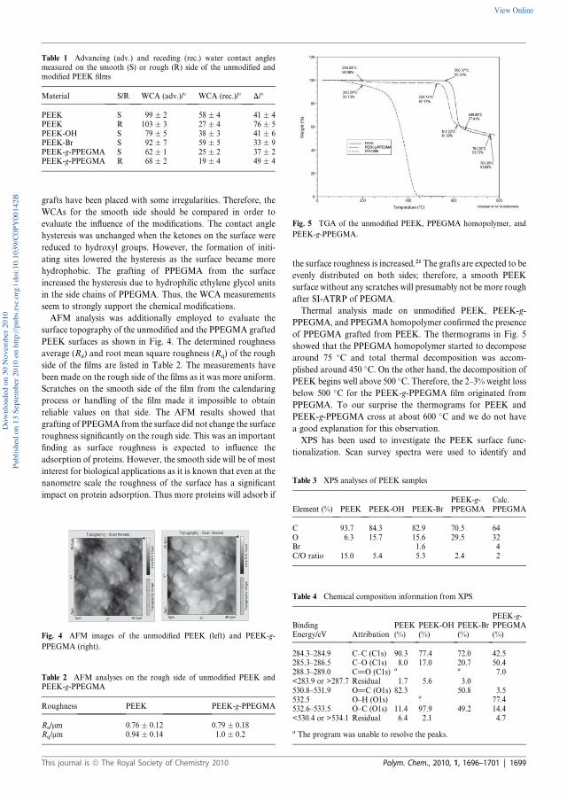
grafts have been placed with some irregularities. Therefore, the
WCAs for the smooth side should be compared in order to
evaluate the influence of the modifications. The contact angle
hysteresis was unchanged when the ketones on the surface were
reduced to hydroxyl groups. However, the formation of initi-
ating sites lowered the hysteresis as the surface became more
hydrophobic. The grafting of PPEGMA from the surface
increased the hysteresis due to hydrophilic ethylene glycol units
in the side chains of PPEGMA. Thus, the WCA measurements
seem to strongly support the chemical modifications.
AFM analysis was additionally employed to evaluate the
surface topography of the unmodified and the PPEGMA grafted
PEEK surfaces as shown in Fig. 4. The determined roughness
average (Ra) and root mean square roughness (Rq) of the rough
side of the films are listed in Table 2. The measurements have
been made on the rough side of the films as it was more uniform.
Scratches on the smooth side of the film from the calendaring
process or handling of the film made it impossible to obtain
reliable values on that side. The AFM results showed that
grafting of PPEGMA from the surface did not change the surface
roughness significantly on the rough side. This was an important
finding as surface roughness is expected to influence the
adsorption of proteins. However, the smooth side will be of most
interest for biological applications as it is known that even at the
nanometre scale the roughness of the surface has a significant
impact on protein adsorption. Thus more proteins will adsorb if
the surface roughness is increased.21 The grafts are expected to be
evenly distributed on both sides; therefore, a smooth PEEK
surface without any scratches will presumably not be more rough
after SI-ATRP of PEGMA.
Thermal analysis made on unmodified PEEK, PEEK-g-
PPEGMA, and PPEGMA homopolymer confirmed the presence
of PPEGMA grafted from PEEK. The thermograms in Fig. 5
showed that the PPEGMA homopolymer started to decompose
around 75 �C and total thermal decomposition was accom-
plished around 450 �C. On the other hand, the decomposition of
PEEK begins well above 500 �C. Therefore, the 2–3% weight loss
below 500 �C for the PEEK-g-PPEGMA film originated from
PPEGMA. To our surprise the thermograms for PEEK and
PEEK-g-PPEGMA cross at about 600 �C and we do not have
a good explanation for this observation.
XPS has been used to investigate the PEEK surface func-
tionalization. Scan survey spectra were used to identify and
Table 1 Advancing (adv.) and receding (rec.) water contact anglesmeasured on the smooth (S) or rough (R) side of the unmodified andmodified PEEK films
Material S/R WCA (adv.)/� WCA (rec.)/� D/�
PEEK S 99 � 2 58 � 4 41 � 4PEEK R 103 � 3 27 � 4 76 � 5PEEK-OH S 79 � 5 38 � 3 41 � 6PEEK-Br S 92 � 7 59 � 5 33 � 9PEEK-g-PPEGMA S 62 � 1 25 � 2 37 � 2PEEK-g-PPEGMA R 68 � 2 19 � 4 49 � 4
Fig. 4 AFM images of the unmodified PEEK (left) and PEEK-g-
PPEGMA (right).
Table 2 AFM analyses on the rough side of unmodified PEEK andPEEK-g-PPEGMA
Roughness PEEK PEEK-g-PPEGMA
Ra/mm 0.76 � 0.12 0.79 � 0.18Rq/mm 0.94 � 0.14 1.0 � 0.2
Fig. 5 TGA of the unmodified PEEK, PPEGMA homopolymer, and
PEEK-g-PPEGMA.
Table 3 XPS analyses of PEEK samples
Element (%) PEEK PEEK-OH PEEK-BrPEEK-g-PPEGMA
Calc.PPEGMA
C 93.7 84.3 82.9 70.5 64O 6.3 15.7 15.6 29.5 32Br 1.6 4C/O ratio 15.0 5.4 5.3 2.4 2
Table 4 Chemical composition information from XPS
BindingEnergy/eV Attribution
PEEK(%)
PEEK-OH(%)
PEEK-Br(%)
PEEK-g-PPEGMA(%)
284.3–284.9 C–C (C1s) 90.3 77.4 72.0 42.5285.3–286.5 C–O (C1s) 8.0 17.0 20.7 50.4288.3–289.0 C]O (C1s) a a 7.0<283.9 or >287.7 Residual 1.7 5.6 3.0530.8–531.9 O]C (O1s) 82.3 50.8 3.5532.5 O–H (O1s) a 77.4532.6–533.5 O–C (O1s) 11.4 97.9 49.2 14.4<530.4 or >534.1 Residual 6.4 2.1 4.7
a The program was unable to resolve the peaks.
This journal is ª The Royal Society of Chemistry 2010 Polym. Chem., 2010, 1, 1696–1701 | 1699
Down
loade
d on 3
0 Nov
embe
r 201
0Pu
blish
ed on
13 S
eptem
ber 2
010 o
n http
://pu
bs.rs
c.org
| doi:
10.10
39/C
0PY0
0142
BView Online
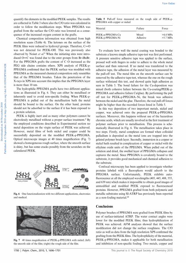
quantify the elements in the modified PEEK samples. The results
are collected in Table 3 where also the C/O ratio was calculated in
order to follow the modification steps. When PPEGMA was
grafted from the surface the C/O ratio was lowered as a conse-
quence of the increased oxygen content in the grafts.
Chemical composition information was obtained from high
resolution scans (Table 4). The ketones on the surface of the
PEEK films were reduced to hydroxyl groups. Therefore, C]O
was not detected for PEEK-OH. This was previously also
observed by Noiset et al.5 When the initiating sites were intro-
duced O]C was found due to the ester groups from Br-iBuBr.
For the PPEGMA grafts the content of C–O increased as the
PEG side chains contains ethers. XPS analysis of PEEK-g-
PPEGMA confirmed that the PEEK surface was modified with
PPEGMA as the measured chemical composition only resembles
that of the PPEGMA brushes. Taken the penetration of the
X-rays in XPS into account this implies that the PPEGMA layer
is more than 10 nm.
The hydrophilic PPEGMA grafts have two different applica-
tions as illustrated in Fig. 6. They can either be metallised or
inherently used to avoid non-specific fouling. When PEEK-g-
PPEGMA is pulled out of the metallisation bath the metal
should be bound to the surface. On the other hand, proteins
should not be adsorbed to the surface if it has been exposed to
a protein solution.
PEEK is highly inert and as many other polymers cannot be
electrolessly metallised without a proper surface treatment.2 By
the employed conditions described in Experimental section no
metal deposition on the virgin surface of PEEK was achieved.
However, metal films of both nickel and copper could be
successfully deposited on the modified PEEK-g-PPEGMA.
Optical microscope images at 40 times magnification (Fig. 7)
showed a homogeneous rough surface, where the smooth surface
is shiny, but has some cracks possibly from the scratches on the
calendared PEEK.
To evaluate how well the metal coating was bonded to the
substrate a known simple adhesive tape-test was first performed.
A pressure sensitive adhesive tape was applied to the surface,
pressed well with fingers in order to adhere to the whole metal
surface and then removed. If no metal was transferred to the
adhesive tape, the adhesion of the metal layer was measured by
the pull-off test. The metal film on the smooth surface can be
removed by the adhesive tape-test, whereas the one on the rough
surface withstand this test, and showed quite high adhesion as
seen in Table 5. The bond failure for the Cu-deposition was
mixed (both cohesive failure between the Cu-coating/PEEK-g-
PPEGMA and adhesive failure Cu/glue). By performing the pull
off test for PEEK-g-PPEGMA–Ni, the break was adhesive
between the nickel and the glue. Therefore, the real pull off forces
might be higher than the recorded forces listed in Table 5.
In this way deposition of two important metals, nickel and
copper, was achieved onto the prepared PEEK-g-PPEGMA
surfaces. Moreover, this happens without use of the hazardous
chromic acids, which are usually involved in the first treatment of
polymer surfaces prior to metallisation. This process is sche-
matically illustrated in Fig. 6. The metallisation takes place in
two steps. Firstly, metal complexes are formed when colloidal
palladium is deposited as the metal ions are trapped into the
gelated polymer brush layer. Secondly, immersion in a copper or
nickel bath resulted in complexation of copper or nickel with the
ethylene oxide units of the PPEGMA. When pulled out of the
solution and dried, the swelled layer of PPEGMA collapses and
captures the metal. Since PPEGMA is covalently bound to the
substrate, it provides good mechanical and chemical adhesion to
the substrate.
Confocal microscopy has been applied to investigate whether
proteins labeled with a fluorophore would adsorb to the
PPEGMA surface. Unfortunately, PEEK exhibits auto-
fluorescence at all the employed wavelengths (405, 445, 488, 555,
and 639 nm) which makes it impossible to obtain good images of
unmodified and modified PEEK exposed to fluorescenced
proteins. However, PPEGMA grafted from both polymeric and
metallic substrates using SI-ATRP has previously been reported
as a non-fouling material.22
Conclusions
Polymer brushes of PPEGMA were grafted from PEEK films by
use of surface-initiated ATRP. The water contact angles were
lower for the modified PEEK films; thus hydrophilization of
PEEK was achieved. AFM analyses showed that the surface
modification did not change the surface roughness. The C/O
ratio as well as data from the high resolution XPS confirmed the
grafting from the PEEK films. The hydrophilicity of the material,
PEEK-g-PPEGMA, makes it applicable for both metallisation
and inhibition of non-specific fouling. Two metals, copper and
Fig. 6 One functionalization with two different applications, electronics
and medical.
Fig. 7 40 times magnification of PEEK-g-PPEGMA with nickel; (left)
the smooth side of the film; (right) the rough side of the film.
Table 5 Pull-off force measured on the rough side of PEEK-g-PPEGMA with copper or nickel
Material Failure Force
PEEK-g-PPEGMA-Cu Mixed >4.4 MPaPEEK-g-PPEGMA-Ni Adhesive >5.7 MPa
1700 | Polym. Chem., 2010, 1, 1696–1701 This journal is ª The Royal Society of Chemistry 2010
Down
loade
d on 3
0 Nov
embe
r 201
0Pu
blish
ed on
13 S
eptem
ber 2
010 o
n http
://pu
bs.rs
c.org
| doi:
10.10
39/C
0PY0
0142
BView Online
nickel, were electroless deposited on modified PEEK surfaces
with quite high adhesion. Pull-off forces higher than 4.4 MPa
and 5.7 MPa were required to remove the deposited copper and
nickel, respectively, from the modified PEEK surfaces.
Acknowledgements
CJF acknowledges the Technical University of Denmark, Novo
Nordisk A/S, and the Danish Agency for Science Technology
and Innovation for financial support. The Ministry of Science
Technology and Innovation is acknowledged for financial
support through grant 61568. Furthermore, we thank Torben
Tang for providing the electroless nickel and copper baths as well
as fruitful discussions, Ilze Viskere for performing the metalli-
zation and pull off tests, Lene Hubert for the XPS results, and
P. S. Ramanujam for the AFM analyses.
References
1 J. J. Pireaux, Synth. Met., 1994, 67, 39–46.2 R. Suchentrunk and K. Heymann, Kunststoff-Metallisierung:Handbuch f€ur Theorie und Praxis, Leuze, Saulgau/W€urtt, 1991.
3 A. Y. Yi, W. Lu, D. F. Farson and L. J. Lee, Adv. Polym. Technol.,2008, 27, 188–198.
4 (a) O. Noiset, Y. J. Schneider and J. Marchand-Brynaert, J. Biomater.Sci., Polym. Ed., 1999, 10, 657–677; (b) O. Noiset, Y. J. Schneider andJ. Marchand-Brynaert, J. Biomater. Sci., Polym. Ed., 2000, 11, 767–786.
5 O. Noiset, C. Henneuse, Y. J. Schneider and J. Marchand-Brynaert,Macromolecules, 1997, 30, 540–548.
6 (a) J. Marchand-Brynaert, G. Pantano and O. Noiset, Polymer, 1997,38, 1387–1394; (b) O. Noiset, Y. J. Schneider and J. Marchand-Brynaert, J. Polym. Sci., Part A: Polym. Chem., 1997, 35, 3779–3790.
7 S. M. Kurtz and J. N. Devine, Biomaterials, 2007, 28, 4845–4869.8 (a) W. A. Braunecker and K. Matyjaszewski, Prog. Polym. Sci., 2007,32, 93–146; (b) N. M. L. Hansen, K. Jankova and S. Hvilsted, Eur.Polym. J., 2007, 32, 255–293; (c) J. A. Opsteen and J. C. M. vanHest, in Macromolecular Engineering, ed. K. Matyjaszewski,Y. Gnanou and L. Leibler, Wiley-VCH, Weinheim, 2007, vol. IV,
ch. 16.4, pp. 2662–2671; (d) N. V. Tsarevsky and K. Matyjaszewski,Chem. Rev., 2007, 107, 2270–2299.
9 (a) R. Barbey, L. Lavanant, D. Paripovic, N. Sch€uwer, C. Sugnaux,S. Tugulu and H.-A. Klok, Chem. Rev., 2009, 109, 5437–5527; (b)C. J. Fristrup, K. Jankova and S. Hvilsted, Soft Matter, 2009, 5,4623–4634; (c) D. Roy, M. Semsarilar, J. T. Guthrie and S. Perrier,Chem. Soc. Rev., 2009, 38, 1825–2148; (d) F. J. Xu, K. G. Neohand E. T. Kang, Prog. Polym. Sci., 2009, 34, 719–761.
10 B. Yameen, M. �Alvarez, O. Azzaroni, U. Jonas and W. Knoll,Langmuir, 2009, 25, 6214–6220.
11 X. Liu, H. Chang, Y. Li, W. T. S. Huck and Z. Zheng, ACS Appl.Mater. Interfaces, 2010, 2, 529–535.
12 P. C. Hidber, W. Helbig, E. Kim and G. M. Whitesides, Langmuir,1996, 12, 1375–1380.
13 J. F. Lutz, J. Polym. Sci., Part A: Polym. Chem., 2008, 46, 3459–3470.
14 J. H. Lee, H. B. Lee and J. D. Andrade, Prog. Polym. Sci., 1995, 20,1043–1079.
15 D.L.Elbert and J.A.Hubbell,Annu.Rev.Mater. Sci., 1996, 26, 365–394.16 M. Malmsten, K. Emoto and J. M. Van Alstine, J. Colloid Interface
Sci., 1998, 202, 507–517.17 ISO 4624 (2002) ‘‘Paints and Varnishes—Pull Off-Test for Adhesion’’
and ASTM D 4541-09(2009) ‘‘Standard Test Method for Pull-OffStrength of Coatings Using Portable Adhesion Testers’’.
18 A. Carlmark and E. Malmstrom, J. Am. Chem. Soc., 2002, 124, 900–901.
19 N. Singh, J. Wang, M. Ulbricht, S. R. Wickramasinghe andS. M. Husson, J. Membr. Sci., 2008, 309, 64–72.
20 J. Y. Huang, H. Murata, R. R. Koepsel, A. J. Russell andK. Matyjaszewski, Biomacromolecules, 2007, 8, 1396–1399.
21 K. Rechendorff, M. B. Hovgaard, M. Foss, V. P. Zhdanov andF. Besenbacher, Langmuir, 2006, 22, 10885–10888.
22 (a) F. X. Hu, K. G. Neoh, L. Cen and E. T. Kang, Biomacromolecules,2006, 7, 809–816; (b) B. S. Lee, Y. S. Chi, K. B. Lee, Y. G. Kim andI. S. Choi, Biomacromolecules, 2007, 8, 3922–3929; (c) L. Li,G. P. Yan, J. Y. Wu, X. H. Yu and Q. Z. Guo, J. Macromol. Sci.,Part A: Pure Appl. Chem., 2008, 45, 828–832; (d) N. Singh,X. F. Cui, T. Boland and S. M. Husson, Biomaterials, 2007, 28,763–771; (e) S. Tugulu and H. A. Klok, Biomacromolecules, 2008, 9,906–912; (f) F. J. Xu, Y. L. Li, E. T. Kang and K. G. Neoh,Biomacromolecules, 2005, 6, 1759–1768; (g) F. J. Xu, J. P. Zhao,E. T. Kang, K. G. Neoh and J. Li, Langmuir, 2007, 23, 8585–8592;(h) F. J. Xu, S. P. Zhong, L. Y. L. Yung, E. T. Kang andK. G. Neoh, Biomacromolecules, 2004, 5, 2392–2403; (i) G. Q. Zhai,E. T. Kang and K. G. Neoh, Macromolecules, 2004, 37, 7240–7249.
This journal is ª The Royal Society of Chemistry 2010 Polym. Chem., 2010, 1, 1696–1701 | 1701
Down
loade
d on 3
0 Nov
embe
r 201
0Pu
blish
ed on
13 S
eptem
ber 2
010 o
n http
://pu
bs.rs
c.org
| doi:
10.10
39/C
0PY0
0142
BView Online
C
C.J. Fristrup, K. Jankova, R. Eskimergen, J.T. Bukrinsky, and S. Hvilsted, Protein repellent hydrophilic grafts prepared by surface-initiated atom transfer radical polymerization from polypropylene, Polym. Chem., 3 (2012) 198-203. © 2012 The Royal Society of Chemistry Reproduced by permission of The Royal Society of Chemistry

Protein repellent hydrophilic grafts prepared by surface-initiated atomtransfer radical polymerization from polypropylene
Charlotte Juel Fristrup,a Katja Jankova,a R€uya Eskimergen,b Jens T. Bukrinskyb and Søren Hvilsted*a
Received 3rd August 2011, Accepted 24th October 2011
DOI: 10.1039/c1py00347j
Grafting of poly(ethylene glycol)methacrylate (PEGMA) and N,N-dimethylacrylamide (DMAAm)
from UV-initiator modified polypropylene (PP) was performed by Surface-Initiated Atom Transfer
Radical Polymerization (SI-ATRP). The modification and hydrophilization of the PP substrates were
confirmed with Attenuated Total Reflectance (ATR) Fourier Transform Infrared (FTIR) spectroscopy
and Water Contact Angle (WCA) measurements. Confocal fluorescence microscopy of modified and
unmodified substrates immersed in labelled insulin aspart showed superior repulsion of this protein for
the poly(PEGMA) grafts, due to the achieved architecture.
Introduction
Non-specific fouling needs to be suppressed at interfaces between
solid substrates and liquids for many applications within the
biomedical field, e.g. pharmaceutical packaging, drug delivery
systems, implantable devices, biosensors, and microarrays.1 For
protein drug formulations acceptable chemical and physical
stability of the protein as well as a low level of non-toxic leach-
ables are very important factors. In addition to that, inhibition of
fouling is crucial in order for the drug to obtain compatibility
with a substrate. Polypropylene (PP) is a substrate of interest for
pharmaceutical packaging and delivery systems, due to its
resistance to most chemicals, high fatigue strength, and good
processability. However, PP is hydrophobic like most commer-
cially available thermoplastics, which makes it less compatible
with proteins compared with hydrophilic polymers.2 Therefore,
the aim was to graft hydrophilic polymers from a PP substrate in
order to improve the compatibility with a protein drug
formulation.
Hydrophilic polymers can be grafted by Surface-Initiated
Atom Transfer Radical Polymerization (SI-ATRP). This poly-
merization method can be performed on various polymeric,
metallic or inorganic surfaces, and has proven to be a very robust
and versatile grafting procedure with a controlled character.1,3 It
has been greatly exploited and its use as a technique to develop
biofunctional coatings is well documented and rapidly
growing.1,4 The key step in grafting polymers through SI-ATRP
is generation of initiating sites on the entire substrate. In prin-
ciple, convenient procedures to transform different functional
groups (OH, CHO, NH, NH2) on the surface to initiating groups
for the chosen SI polymerization method have been identified
where the most exploited groups are surface hydroxyls, e.g., in
cellulose.5 Recently poly(ether ether ketone) (PEEK) has been
immobilized with ATRP initiating moieties6,7 after trans-
formation of the surface ketones to hydroxyls by a well estab-
lished protocol.8 However, efficient ways for creating initiating
sites for ATRP on inert surfaces are still challenging. One of the
few reported methods, which has been successful, uses
an UV-ATRP initiator, benzophenonyl bromoisobutyrate
(BP-iBUBr). Firstly, it was proposed and used for PP,9 later it
was also adapted for carbon nanotubes,10 and it was applied in
the present investigations. When initiating groups on the surface
are formed, SI-ATRP of a desired monomer can easily be per-
formed in bulk, organic solvent or aqueous media. For biological
applications mostly hydrophilic polymers are grafted, and the
preferred medium is water or water/methanol. In this study it was
decided to graft poly(ethylene glycol)methacrylate (PEGMA)
andN,N-dimethylacrylamide (DMAAm) from PP. PEGMAwas
selected as coatings of poly(ethylene glycol) (PEG) are known to
inhibit non-specific fouling due to their water solubility, hydro-
philicity, and chain mobility.2,11 Poly(DMAAm) was of interest
as it has been grafted from chromatographic packing material
and prevented fouling during separation of proteins.12
In general, SI controlled polymerizations generate thin cova-
lently linked polymer coatings on a substrate.3 The entire new
surface layer on the substrate is different from the bulk and its
properties. Thus new functionality to the substrate is added.
Moreover, surface grafting influences the physical and chemical
interactions of the substrate with the surrounding environment.
This is essential for the application in question.
SI-ATRP was performed in a large scale on a substantial
amount of test specimen in order to have sufficient modified
substrates for a stability study to investigate the chemical and
physical stability of insulin stored at three different tempera-
tures.13 The modification was confirmed with Attenuated Total
aDanish Polymer Centre, Department of Chemical and BiochemicalEngineering, Technical University of Denmark, Building 227, DK-2800Kgs. Lyngby, Denmark. E-mail: [email protected]; Fax: +45 4588 2161;Tel: +45 4525 2965bNovo Nordisk A/S, Novo All�e, DK-2880 Bagsværd, Denmark
198 | Polym. Chem., 2012, 3, 198–203 This journal is ª The Royal Society of Chemistry 2012
Dynamic Article LinksC<PolymerChemistry
Cite this: Polym. Chem., 2012, 3, 198
www.rsc.org/polymers PAPER
Down
loade
d on 1
4 Dec
embe
r 201
1Pu
blish
ed on
14 N
ovem
ber 2
011 o
n http
://pu
bs.rs
c.org
| doi:
10.10
39/C
1PY0
0347
JView Online / Journal Homepage / Table of Contents for this issue
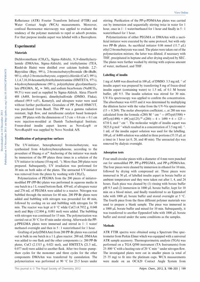
Reflectance (ATR) Fourier Transform Infrared (FTIR) and
Water Contact Angle (WCA) measurements. Moreover,
confocal fluorescence microscopy was applied to evaluate the
tendency of the polymer materials to repel or adsorb proteins.
For that purpose insulin aspart was labeled with a fluorophore.
Experimental
Materials
Dichloromethane (CH2Cl2, Sigma-Aldrich), N,N-dimethylacry-
lamide (DMAAm, Sigma-Aldrich), and triethylamine (TEA,
Riedel-de Ha€en) were distilled over calcium hydride. 2,20-Bipyridine (Bipy, 99%), 2-bromoisobutyrylbromide (Br-iBuBr,
98%), ethyl-2-bromoisobutyrate, copper(I) chloride (CuCl, 99%),
1,1,4,7,10,10-hexamethyltriethylenetetramine (HMTETA, 97%),
4-hydroxybenzophenone (98%), poly(ethylene glycol)methacry-
late (PEGMA, Mn z 360), and sodium bicarbonate (NaHCO3,
99.5%) were used as supplied by Sigma-Aldrich. Alexa Fluor�488 (A488, Invitrogen), dimethylsulfoxide (DMSO, Fluka),
ethanol (99.9 vol%, Kemetyl), and ultrapure water were used
without further purification. Granulate of PP, Purell HM671T,
was purchased from Basell. This PP was a gamma radiation
resistant, high flow, and metallocene catalyst based homopol-
ymer. PP plates with the dimensions of 3.5 cm � 0.6 cm � 0.1 cm
were injection-moulded at Danish Technological Institute.
Freeze-dried insulin aspart known as NovoLog� or
NovoRapid� was supplied by Novo Nordisk A/S.
Modification of polypropylene surfaces
The UV-initiator, benzophenonyl bromoisobutyrate, was
synthesized from 4-hydroxybenzophenone, according to the
procedure of Huang et al.9 Anchoring of the initiator was made
by immersion of the PP plates three times in a solution of the
UV-initiator in toluene (10 mg mL�1). More than 200 plates were
prepared. Subsequently, UV irradiation was performed for
30 min on both sides of the plates. The unreacted UV-initiator
was removed from the plates by washing with CH2Cl2.
Polymerization of PEGMA from the 200 pieces of initiator-
modified PP (PP-Br) plates was performed in aqueous media in
one batch in a 1 L round bottom flask. 459 mL of ultrapure water
and 276 mL of PEGMA were added to a reactor. Nitrogen was
bubbled through the mixture for 60 min. 200 PP-Br plates were
added and bubbling with nitrogen was proceeded for 40 min,
followed by cooling on ice and bubbling with nitrogen for 50
min. The reactor was kept at 0 �C while CuCl (4.7932 g, 0.048
mol) and Bipy (12.804 g, 0.081 mol) were added. The bubbling
with nitrogen was continued for 15 min. The polymerization was
carried out at 30 �C for 45 min under stirring. Afterwards the PP-
g-PPEGMA plates were immersed and stirred in 1 : 1 water/
methanol overnight and then in 5 : 1 water/ethanol for 1 hour.
Grafting of poly(DMAAm) from 200 PP-Br plates was carried
out in bulk in one batch in a 1 L glass reactor. 200 mL DMAAm
was added to one flask and the other components i.e. 200 PP-Br
plates, CuCl (2.1315 g, 0.021 mol), and HMTETA (21.5 mL,
0.077 mol) were added to another flask. After two freeze–pump–
thaw cycles for the monomer and three cycles for the other
components DMAAm was transferred by cannulation. The
polymerization was performed at 90 �C for 23.5 hours under
stirring. Purification of the PP-g-PDMAAm plates was carried
out by immersion and sequentially stirring twice in water for 1
hour, once in 1 : 1 water/methanol for 1 hour and finally in 5 : 1
water/ethanol for 1 hour.
Polymerizations of either PEGMA or DMAAm with a sacri-
ficial initiator were executed by the same protocol, but with only
two PP-Br plates. As sacrificial initiator 0.06 mmol (11.7 mL)
ethyl 2-bromobutyrate was used. The plates were taken out of the
polymerization mixture, the latter was diluted, if necessary with
THF, precipitated in heptane and after drying analyzed by SEC.
The plates were further washed by stirring with copious amount
of water, methanol, and THF.
Labelling of insulin
1 mg of A488 was dissolved in 100 mL of DMSO. 3.5 mg mL�1 of
insulin aspart was prepared by transferring 8 mg of freeze-dried
insulin aspart (containing water) to 1.5 mL of 0.1 M borate
buffer, pH 9.5. The insulin solution was stirred for 30 min.
UV-Vis spectroscopy was applied to confirm the concentration.
The absorbance was 4.035 and it was determined by multiplying
the dilution factor with the value from the UV-Vis spectrometer
(15 � 0.269). The molar absorption coefficient, 3, at 280 nm was
calculated from the formula 3(280) M�1 cm�1 ¼ (#Trp)/(5500) +
(#Tyr)(1490) + (#Cys)(125).14 3(280) ¼ 4 � 1490 + 6 � 125 ¼6710 L mol�1 cm�1. The molecular weight of insulin aspart was
5825.8 g mol�1 which resulted in a concentration of 3.5 mg mL�1.
1 mL of the insulin aspart solution was used for the labelling.
100 mL of A488 solution was added in three portions (33.33 mL at
a time) in 1 hour (at 0, 20, and 40 min). The unreacted dye was
removed by dialysis overnight.
Adsorption tests
Four small circular pieces with a diameter of 4 mm were punched
out for unmodified PP, PP-g-PPEGMA, and PP-g-PDMAAm.
The four pieces were cleaned by immersion in ethanol for 10 min,
followed by drying with compressed air. Three pieces were
immersed in 50 mL of labelled insulin aspart in borate buffer at
ambient temperature and they were taken out after 1, 4, and 24
hours. Each piece was cleaned by (1) rinsing with borate buffer
pH 9.5 and (2) immersion in 1000 mL borate buffer, kept for 10
min on a blood mixer, and finally transferred to an Eppendorf
tube with 1000 mL borate buffer and stored overnight at 5 �C.The fourth piece from the three different polymer materials was
used to prepare a blank sample. The piece was immersed in
a 1000 mL borate buffer and mixed for 10 min. Subsequently, it
was transferred to another Eppendorf tube with 1000 mL borate
buffer and stored under the same conditions as the samples.
Methods
ATR FTIR spectra were obtained using a Spectrum One spec-
trometer from Perkin Elmer which was equipped with a universal
ATR sample accessory. Thermogravimetric analysis (TGA) was
performed on a TGA Q500 instrument (TA Instruments) from
25–800 �Cwith a heating rate of 20 �Cmin�1 under nitrogen flow.
The investigated plates were cut in smaller pieces (a total of
25–35 mg) to fit into the platinum cups. WCA measurements
were made on an OCA20 Contact Angle System from
This journal is ª The Royal Society of Chemistry 2012 Polym. Chem., 2012, 3, 198–203 | 199
Down
loade
d on 1
4 Dec
embe
r 201
1Pu
blish
ed on
14 N
ovem
ber 2
011 o
n http
://pu
bs.rs
c.org
| doi:
10.10
39/C
1PY0
0347
J
View Online

Dataphysics with a temperature controller. The temperature was
set to 25 �C. The dynamic method called ‘‘sessile drop (needle
in)’’ was used and the WCAs were computed using ‘‘Ellipse
Fitting’’. The measurements were carried out on three drops of
deionised water at different spots and three values for both the
advancing and receding angles were used to determine the
average value. UV irradiation of the PP plates in order to anchor
the initiator was performed with a UVA light source purchased
from SolData Instruments. The light from the mercury vapour
lamp had a broad maximum output at 365 nm. Intensity of the
light was measured with a Sentry� UV detector which detected
UV radiation from 280–400 nm. Typical measurements on the
UV lamp were in the range of 7.2–7.9 mW cm�2. A Shimadzu
UV1700, UV-Vis spectrophotometer was applied to determine
the concentration of insulin aspart. Measurements were carried
out at 280 nm. The samples were diluted 15 times. Reset to zero
was made on 0.1 M borate buffer, pH 9.5. Confocal fluorescence
microscopy was performed on a Confocal Laser Scanning
Microscope, CLSM 510 Meta from Zeiss with Zen710 software.
Pinhole was set to 4.24 airy units. 2D-images were obtained with
an objective of 10�magnification, and the following settings, tile
scan 2 � 2 and 8 bit image, were applied.
Size exclusion chromatography (SEC) of the polymers
produced with the sacrificial initiator was performed in THF at
room temperature at a flow rate of 1.0 mL min�1 on a set of PL
guard and 2 PL gel mixed D columns (Polymer Laboratories),
calibrated versus polystyrene narrow molar mass standards.
Additionally SEC in DMF was used to characterize the poly
(DMAAm) free polymer. These SEC experiments were per-
formed on an EcoSEC semi-microsystem from Polymer Stan-
dard Service (PSS) employing 100 �A and 300 �A PFG micro-
columns with a bead size of 7 micrometre. The instrument was
equipped with 2 detectors—a dual flow refractive index and
a UV. DMF with 0.05 M LiCl was used as eluent at 50 �C. Themolecular weights were estimated using the calibration curve
constructed with poly(methyl methacrylate) (PMMA) standards
and WinGPC Unity software from PSS.
Results and discussion
Initiating groups for Atom Transfer Radical Polymerization
(ATRP) were first anchored on the PP surface before the graft
polymerization could take place. Covalent C–C bonds should
then be formed between the initiator and the PP when irradiated
with UV light at 365 nm. Hydrophilic polymers of either poly
(PEGMA) or poly(DMAAm) were grafted from the initiator
modified PP surface using the conditions in Fig. 1.
From the ATR FTIR spectra (Fig. 2) the presence of the poly
(PEGMA) and poly(DMAAm) anchored to the PP substrates
was observed. The carbonyl group (C]O) from the ester in the
initiator and poly(PEGMA) resulted in a stretching band at
1734 cm�1 whereas the C]O absorption band from the amide in
poly(DMAAm) appeared at 1634 cm�1. At 1256 cm�1 the C–O
and C–N stretching bands were observed which were from the
amide in poly(DMAAm) and the O]C–O in initiator and poly
(PEGMA). The absorption band at 1101 cm�1 was attributed to
the characteristic absorption of the C–O in the ethylene oxide
O–CH2–CH2–O–CH2– side chain. It was not possible to identify
the initiating sites on the PP-Br plates with ATR FTIR, which
other groups also have reported.5a,9,15 In principle, FT-IR was
successfully used1 to recognize initiating groups on inorganic and
metallic surfaces; however, it is incredibly difficult to apply
a similar method to demonstrate the presence of initiating sites
on polymeric surfaces. The first paper, which reports a successful
detection of ATRP initiating groups on polymeric substrates, has
applied PEEK films.6 The reason for this observation might be
a more efficient chemical immobilization method than the UV
initiator on PP. A reference sample was prepared in each of the
polymerizations of PEGMA and DMAAm. The reference was
a PP plate, which was subjected to the polymerization condi-
tions, but it had no initiator immobilized. The ATR FTIR
spectra of these 2 samples were identical with pure PP, and
therefore not shown in Fig. 2.
Meticulous gravimetric analyses performed on 15 washed and
carefully dried un-modified PP and PP-g-PPEGMA plates
revealed very small weight gains corresponding to only 0.13 wt%
PPEGMA. Since 1 PP plate has a total surface area of 5 cm2 and
a mass of 188 mg on average only 0.2 mg PPEGMA (0.04 mg
cm�2) is grafted on one plate. However, the same analysis on the
PP-g-PDMAAm plates revealed an average weight gain of
2.1 wt% corresponding to an average of 4 mg PDMAAm
(0.8 mg cm�2) on one plate. In addition, TGA analyses showed
that the PP-g-PDMAAm plates exhibited a weight loss upon
heating of approximately 1.5% that could be assigned to
PDMAAm. If one back calculates, this corresponds to 2.8 mg of
PDMAAm grafted (0.56 mg cm�2) on the PP surface. Thus, the
two different ways (simple gravimetry and TGA) of estimating
the average amount of grafted PDMAAm on the PP plates are
relatively in good agreement. A similar TGA analysis was not
possible in the case of the PP-g-PPEGMA. Without the addi-
tional knowledge of grafting density estimation of the grafted
chain-length is not possible.
WCAs were measured on unmodified PP and PP with the
hydrophilic polymers of either poly(PEGMA) or poly
(DMAAm). Both free polymers produced with the sacrificial
initiator were water soluble, and therefore the WCAs of spin-
coated free poly(PEGMA) or poly(DMAAm) could not be
measured. When grafted, these polymers lowered the advancing
and receding contact angles to some extent. The results in Table 1
show that in both cases the advancing and receding WCAs
decreased. The grafting of poly(PEGMA) or poly(DMAAm) on
the surface also increased the hysteresis due to the hydrophilicity
of the grafts. Thus, the WCAs corroborate the changes in the
grafted PP surface properties.Fig. 1 Grafting of poly(PEGMA) and poly(DMAAm) brushes on the
surface.
200 | Polym. Chem., 2012, 3, 198–203 This journal is ª The Royal Society of Chemistry 2012
Down
loade
d on 1
4 Dec
embe
r 201
1Pu
blish
ed on
14 N
ovem
ber 2
011 o
n http
://pu
bs.rs
c.org
| doi:
10.10
39/C
1PY0
0347
J
View Online
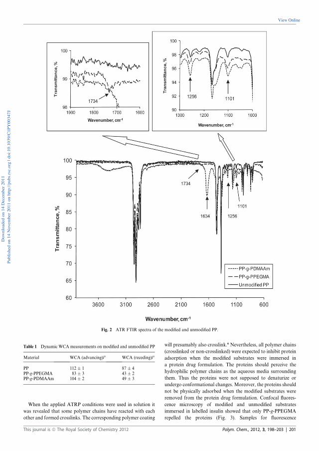
When the applied ATRP conditions were used in solution it
was revealed that some polymer chains have reacted with each
other and formed crosslinks. The corresponding polymer coating
will presumably also crosslink.6 Nevertheless, all polymer chains
(crosslinked or non-crosslinked) were expected to inhibit protein
adsorption when the modified substrates were immersed in
a protein drug formulation. The proteins should perceive the
hydrophilic polymer chains as the aqueous media surrounding
them. Thus the proteins were not supposed to denaturize or
undergo conformational changes. Moreover, the proteins should
not be physically adsorbed when the modified substrates were
removed from the protein drug formulation. Confocal fluores-
cence microscopy of modified and unmodified substrates
immersed in labelled insulin showed that only PP-g-PPEGMA
repelled the proteins (Fig. 3). Samples for fluorescence
Fig. 2 ATR FTIR spectra of the modified and unmodified PP.
Table 1 Dynamic WCA measurements on modified and unmodified PP
Material WCA (advancing)/� WCA (receding)/�
PP 112 � 1 87 � 4PP-g-PPEGMA 83 � 3 43 � 2PP-g-PDMAAm 104 � 2 49 � 3
This journal is ª The Royal Society of Chemistry 2012 Polym. Chem., 2012, 3, 198–203 | 201
Down
loade
d on 1
4 Dec
embe
r 201
1Pu
blish
ed on
14 N
ovem
ber 2
011 o
n http
://pu
bs.rs
c.org
| doi:
10.10
39/C
1PY0
0347
J
View Online

microscopy were taken out and analyzed after 1, 4, and 24 hours.
The areas with adsorbed insulin increased over time on PP-g-
PDMAAmwhereas no visible difference was observed between 4
and 24 hours for unmodified PP.
The efficiency of the crosslinked poly(PEGMA) grafts to repel
labelled insulin seemed to be high and it is expected to be durable
for a long time as the polymer chains are covalently attached to
the surface. Adsorption of labelled insulin to PP-g-PDMAAm
happened instantly and either the amount of denaturized insulin
was increased or aggregates were formed. Factors like grafting
density of the hydrophilic polymer and the size of the protein will
influence the ability to inhibit fouling. Fouling has previously
been observed for poly(DMAAm) grafts with low grafting
density (in the mushroom regime).12 The grafting density of poly
(DMAAm) and poly(PEGMA) ought to be comparable in this
study. It might even be higher for poly(DMAAm) as PEGMA
has side chains of about six ethylene oxide units. The crosslinked
architecture of poly(PEGMA) must make the difference (Fig. 4).
Polymerization in the presence of a sacrificial initiator is
a widespread method to characterize polymer chains which are
claimed to be comparable with the polymer grafts. Polymeriza-
tion with a sacrificial initiator was conducted to try to improve
the part about characterization of the polymer grafts.
PP plates with the attached hydrophilic poly(PEGMA) have
a smooth surface, while the non-covalently attached poly
(PEGMA) produced in solution from the sacrificial initiator
appears to be crosslinked as well, thus determining the molecular
weight characteristics was impossible. As seen in Fig. 5 the free
polymer is even sticking onto the surface of PP. The polymeri-
sation of PEGMA with the sacrificial initiator was also prepared
in methanol. The free poly(PEGMA) from polymerization in
methanol was soluble in alcohols, water and THF, and had aMn
Fig. 3 Overlay of images from transmission and confocal fluorescence microscopy of substrates immersed in labelled insulin. Unmodified PP after (a)
1 hour, (b) 4 hours, and (c) 24 hours; PP-g-PDMAAm after (d) 1 hour, (e) 4 hours, and (f) 24 hours; PP-g-PPEGMA after (g) 1 hour, (h) 4 hours, and
(i) 24 hours.
202 | Polym. Chem., 2012, 3, 198–203 This journal is ª The Royal Society of Chemistry 2012
Down
loade
d on 1
4 Dec
embe
r 201
1Pu
blish
ed on
14 N
ovem
ber 2
011 o
n http
://pu
bs.rs
c.org
| doi:
10.10
39/C
1PY0
0347
J
View Online
of 6700 and a PDI of 1.18 (SEC in THF with PS calibration).
However, this result does not imply that the polymer on the
surface has the same characteristics when water was used as
a solvent. Usually methanol is added to slow down the very fast
polymerization of hydrophilic monomers in water.16
The same experiment when using DMAAm in the presence of
a sacrificial initiator produced a free polymer with Mn ¼ 2100
and PDI ¼ 1.17 (SEC in DMF with PMMA standards). Addi-
tionally, low grafting density combined with short poly
(DMAAm) chains may be the explanation for the absence of
repellence of insulin from poly(DMAAm) modified surfaces by
the conditions used.
Rejection of the relatively small size protein, insulin, is very
dependent on sufficient grafting density or surface coverage in
general. Groll et al.17 have compared linear and star PEG coated
on silicon substrates with respect to the repulsion of insulin and
the larger protein, lysozyme. In agreement with theoretical
predictions they found that the branched structure of the star
PEG and linear PEG with high grafting density could repel
insulin. When the grafting density was lower only lysozyme was
repelled. Therefore, the crosslinks between the poly(PEGMA)
grafts must be able to compensate for a lower grafting density.
Moreover, the antifouling properties of poly(DMAAm) might be
more dependent on a high grafting density than other protein
repellent hydrophilic grafts.
Conclusions
Poly(PEGMA) and poly(DMAAm) were grafted from PP using
SI-ATRP. Lowering of the WCAs was observed after grafting of
the polymers, thus hydrophilization of PP was achieved. ATR
FTIR spectra confirmed the modifications of PP with poly
(PEGMA) and poly(DMAAm), respectively. Poly(PEGMA) has
presumably crosslinked as previously studied with homo-
polymerization of PEGMA in water formed a gel. The cross-
linked poly(PEGMA) on the surface formed a very smooth film
and showed excellent repulsion of labelled insulin aspart after 24
hours of exposure. Therefore, the poly(PEGMA) coating has the
possibility of making polymer materials more usable for devices
in contact with protein drug formulations.
Acknowledgements
CJF acknowledges the Technical University of Denmark, Novo
Nordisk A/S, and the Danish Agency for Science Technology
and Innovation for financial support. Furthermore, we thank
Monika Butrimait�e for the modification with PEGMA and Helle
Markussen Nordholm from FeF Chemicals A/S for the assis-
tance with UV-Vis spectroscopy and the confocal fluorescence
microscopy. Irakli Javakhishvili is acknowledged for performing
the SEC in DMF.
References
1 C. J. Fristrup, K. Jankova and S. Hvilsted, Soft Matter, 2009, 5,4623–4634.
2 (a) D. L. Elbert and J. A. Hubbell, Annu. Rev. Mater. Sci., 1996, 26,365–394; (b) J. H. Lee, H. B. Lee and J. D. Andrade, Prog. Polym.Sci., 1995, 20, 1043–1079; (c) M. Malmsten, K. Emoto andJ. M. Van Alstine, J. Colloid Interface Sci., 1998, 202, 507–517.
3 R. Barbey, L. Lavanant, D. Paripovic, N. Sch€uwer, C. Sugnaux,S. Tugulu and H.-A. Klok, Chem. Rev., 2009, 109, 5437–5527.
4 F. J. Xu, K. Neoh and E. T. Kang, Prog. Polym. Sci., 2009, 34, 719–761.
5 (a) A. Carlmark and E. Malmstrom, J. Am. Chem. Soc., 2002, 124,900–901; (b) D. Plackett, K. Jankova, H. Egsgaard and S. Hvilsted,Biomacromolecules, 2005, 6, 2474–2484; (c) D. Roy, M. Semsarilar,J. T. Guthrie and S. Perrier, Chem. Soc. Rev., 2009, 38, 2046–2064.
6 C. J. Fristrup, K. Jankova and S. Hvilsted, Polym. Chem., 2010, 1,1696–1701.
7 B. Yameen, M. Alvarez, O. Azzaroni, U. Jonas and W. Knoll,Langmuir, 2009, 25, 6214–6220.
8 (a) O. Noiset, Y. J. Schneider and J. Marchand-Brynaert, J. Polym.Sci., Part A: Polym. Chem., 1997, 35, 3779–3790; (b) O. Noiset,C. Henneuse, Y. J. Schneider and J. Marchand-Brynaert,Macromolecules, 1997, 30, 540–548.
9 J. Huang, H. Murata, R. R. Koepsel, A. J. Rusell andK. Matyjaszewski, Biomacromolecules, 2007, 8, 1396–1399.
10 A. E. Daugaard, K. Jankova, J. Bøgelund, J. K. Nielsen andS. Hvilsted, J. Polym. Sci., Part A: Polym. Chem., 2010, 48, 4594–4601.
11 J. F. Lutz, J. Polym. Sci., Part A: Polym. Chem., 2008, 46, 3459–3470.12 B. R. Coad, B. M. Steels, J. N. Kizhakkedathu, D. E. Brooks and
C. A. Haynes, Biotechnol. Bioeng., 2007, 97, 574–587.13 C. J. Fristrup, K. Jankova, R. Eskimergen, J. T. Bukrinsky and
S. Hvilsted, Eur. J. Pharm. Sci., submitted.14 C. N. Pace, F. Vajdos, L. Fee, G. Grimsley and T. Gray, Protein Sci.,
1995, 4, 2411–2423.15 N. Singh, J. Wang, M. Ulbricht, S. R. Wickramasinghe and
S. M. Husson, J. Membr. Sci., 2008, 309, 64–72.16 N. V. Tsarevsky and K. Matyjaszewski, Chem. Rev., 2007, 107, 2270–
2299.17 J. Groll, Z. Ademovic, T. Ameringer, D. Klee and M. Moeller,
Biomacromolecules, 2005, 6, 956–962.
Fig. 4 Crosslinked hydrophilic grafts of poly(PEGMA) were able to
repel labelled insulin whereas insulin adsorbed onto the surface with poly
(DMAAm) brushes when the substrates were pulled out of a protein
solution as visualized.
Fig. 5 PP plates with hydrophilic poly(PEGMA) grafted in the absence
(left) and in the presence (right) of a sacrificial initiator.
This journal is ª The Royal Society of Chemistry 2012 Polym. Chem., 2012, 3, 198–203 | 203
Down
loade
d on 1
4 Dec
embe
r 201
1Pu
blish
ed on
14 N
ovem
ber 2
011 o
n http
://pu
bs.rs
c.org
| doi:
10.10
39/C
1PY0
0347
J
View Online
D
C.J. Fristrup, K. Jankova, R. Eskimergen, J.T. Bukrinsky, and S. Hvilsted, Stability of AspB28 insulin exposed to modified and unmodified polypropylene, Protein Peptide Lett., 22 (2015) 635-643. © 2015 Bentham Science Publishers Reproduced by permission of Bentham Science Publishers


Send Orders for Reprints to [email protected]
Protein & Peptide Letters, 2015, 22, 635-643 635
Stability of AspB28
Insulin Exposed to Modified and Unmodified Polypropylene
Charlotte J. Fristrup†a
, Katja Jankovaa, Rüya Eskimergen
b, Jens T. Bukrinsky
§b and Søren Hvilsted*
a
aDanish Polymer Centre, Department of Chemical and Biochemical Engineering, Building 227,
Technical University of Denmark, DK-2800 Kgs. Lyngby, Denmark; bNovo Nordisk A/S, Novo Allé,
DK-2880 Bagsværd, Denmark
Abstract: Polypropylene (PP) plates have been modified with two different hydrophilic polymeric
materials, poly(N,N-dimethylacrylamide) (poly(DMAAm)) and poly(poly(ethylene glycol)methacry-
late) (poly(PEGMA)) in order to reduce insulin adsorption when the plates were exposed to insulin
aspart (AspB28
insulin). The influence of surface modification on the chemical and physical stability of
AspB28
insulin was evaluated by two chromatographic methods, size exclusion chromatography (SEC)
and reverse phase high pressure liquid chromatography (RP-HPLC) and the Thioflavin T assay. A
clear difference in the stability of AspB28
insulin was observed between the three tested surfaces. PP coated with
poly(DMAAm) resulted in a poor chemical stability and a significantly improved physical stability compared with un-
modified PP. In addition to this a lower phenol concentration was observed for the poly(DMAAm) coating. The results
from the poly(PEGMA) coating looked very promising with respect to the stability of AspB28
insulin in comparison with
the data from unmodified PP and the poly(DMAAm) coating. Two hydrophilic coatings have been tested and surprisingly
a difference in AspB28
insulin stability was observed. Therefore, AspB28
insulin adsorption and stability will be influenced
by more than the hydrophilicity of the surface.
Keywords: Chemical stability, hydrophilic coating, insulin fibrillation, physical stability, surface initiated polymerization.
1. INTRODUCTION
Protein drugs are exposed to a diversity of solid-liquid interfaces during production, storage and use including proc-ess equipment, primary packaging materials and medical devices. Polymers are increasingly replacing metals and glass in many of these applications and interaction of pro-teins at such polymer surfaces are well known to affect the physical stability of the proteins in solution. In the field of diabetes treatment, compatibility of the polymer materials with insulin is extremely important [1-3]. It is well-known that the surface characteristics including the hydrophobicity will have an effect on the quantitative and qualitative pa-rameters describing the protein adsorption [4-6]. Moreover, it has been shown that protein fibrillation can be induced by hydrophobic surfaces [7,8]. Insulin is a protein comprised by 51 amino acids in two peptide chains connected through two out of three disulphide bridges. The insulin molecule has several hydrophobic patches on the surface of the molecule that drives the formation of the multimeric species such as dimers and hexamers [9]. Several species are thus present in solution. Sluzky et al.
[10]
proposed that the structure of the
*Address correspondence to this author at the Danish Polymer Centre, De-
partment of Chemical and Biochemical Engineering, Building 227, Techni-
cal University of Denmark, DK-2800 Kgs. Lyngby, Denmark; Tel: 45 4525 2965; Fax: 45 4593 2906; E-mail: [email protected]
Present Address: †CJF, Coloplast A/S, Holtedam 1, DK-3050 Humlebæk, Denmark §JTB, Novozymes Biopharma DK A/S, Krogshøjvej 36, DK-2880 Bagsværd, Denmark
monomer is changed when exposed and adsorbed to a hy-drophobic surface. This unfolded or misfolded species is thought as a possible initiator of the fibrillation process [10-13]. Studies have shown that the monomeric species adsorb to hydrophobic surfaces to a greater extend than the hexamer and the dimer [10,14] while results from other studies sug-gest that this is dependent on the nature of the surface [14,15]. In this study insulin aspart (Asp
B28 insulin) was cho-
sen as it is of interest for e.g. continuous subcutaneous infu-sion and promising results in simulated use in infusion pumps have been reported [16].
The polymeric material in contact with the drug should fulfil a number of requirements besides the typical require-ments like adequate mechanical properties and suitability for mass production. The material should be chemically resistant towards excipients of the drug formulation. Moreover, it should be suitable for sterilisation, have good barrier proper-ties towards water, preservatives and preferably gases. It should comply with the existing regulations regarding the amount and toxicity of leachables. The number of commer-cially available polymer-based materials which can be used is rather limited. Moreover, polymeric materials are typically hydrophobic, which is known to be a disadvantage with re-spect to protein adsorption. Therefore, modification of sur-face properties may expand the utilisation of polymers in medical devices for protein delivery [17,18].
This study has focused on improving polymer compati-bility with insulin by grafting a hydrophilic polymer coating
1875-5305/15 $58.00+.00 © 2015 Bentham Science Publishers

636 Protein & Peptide Letters, 2015, Vol. 22, No. 7 Fristrup et al.
from the surface of substrates. The technique Surface-Initiated Atom Transfer Radical Polymerization (SI-ATRP) was applied for the grafting as it is a controlled radical po-lymerization method [19,20]. Thus, one will obtain narrow molecular weight distributions and controlled chain lengths. The substrates were made of polypropylene (PP) and the PP plates were functionalized with an ATRP initiator covalently linked to the plates by irradiation with UV light [21,22]. Hy-drophilic coatings were prepared from the initiator function-alized PP by SI-ATRP of the monomers poly(ethylene gly-col)methacrylate (PEGMA) and N,N-dimethylacrylamide (DMAAm). PEGMA was selected as coatings of poly(ethyl-ene glycol) (PEG) are known to inhibit non-specific fouling due to their water solubility, hydrophilicity, and chain mobil-ity [23-26]. Poly(DMAAm) was of interest as it has been grafted from chromatographic packing material and prevented fouling during separation of proteins [27]. Modified and unmodified PP plates were immersed in insu-lin solutions in order to investigate the chemical and physical stability of Asp
B28 insulin by two chromatographic methods
and Thioflavin T (ThT) assay, respectively. AspB28
insulin stored in siliconized glass was used as a reference because similar results are well-documented. The results from this study will compare the influence of modified PP with the unmodified PP on the stability of Asp
B28 insulin.
2. MATERIALS AND METHODS
Insulin aspart (AspB28
insulin) has one amino acid in posi-tion B28, which is a proline in wild type human insulin, sub-stituted with an aspartic acid residue. Asp
B28 insulin U100,
which is marketed under the name NovoLog® or No-voRapid®, was supplied by Novo Nordisk A/S with the fol-lowing composition: Zn
2+ 19.6 �g/mL, Na2HPO4,2H2O 1.25
mg/mL, glycerol 16 mg/mL, NaCl 0.58 mg/mL, pH 7.2-7.6, the solution is preserved with m-cresol (1.72 mg/mL), and phenol (1.50 mg/mL). Granulate of PP, Purell HM671T was purchased from Basell. This PP was a gamma radiation resis-tant, high flow, and metallocene catalyst based ho-mopolymer.
2.1. Chemicals
Analytical grades of acetonitrile, L-arginine, glacial ace-tic acid, o-phosphoric acid, and sodium sulphate were used as supplied by Merck. 6N hydrochloric acid (HCl, VWR), Milli-Q water (in house), nitric acid (HNO3, VWR), and Thioflavin T (ThT, Sigma-Aldrich) were used without fur-ther purification.
2.2. Sample Preparation
PP plates were injection moulded at Danish Technologi-cal Institute in the dimensions 3.5 cm x 0.6 cm x 0.1 cm. The plates were modified with two different coatings according to a procedure published elsewhere [22]. The coatings were covalently attached to PP and consisted of either poly(PEGMA) or poly(DMAAm) grafts (Figure 1).
Dynamic water contact angle measurements confirmed the hydrophilization of the PP plates achieved by the two coatings. It was not possible to determine whether one
Figure 1. The surface modification on PP resulted in two hydro-
philic coatings, poly(PEGMA) and poly(DMAAm).
coating was more hydrophilic than the other. On one hand, the poly(PEGMA) had the lowest advancing and receding angles, 83°±3° and 43°±2°. The values for the poly (DMAAm) coating were 104°±2° and 49°±3°. On the other hand, the hysteresis was larger for poly(DMAAm) coating than for poly(PEGMA) coating, 55°±3° as opposed to 40°±4°.
Two plates were placed in a siliconized glass cartridge and filled with 2.2 mL Asp
B28 insulin U100 i.e. the exposure
ratio was 4.6 cm2/mL. The curvature of both coatings was
unknown; therefore, surface area of the plates was applied to calculate the exposure ratio. The siliconized glass cartridges were closed with a plunger and a cap.
Blank samples were also included which consisted of 2.6 mL Asp
B28 insulin U100 without plates in siliconized glass
cartridges with plungers and caps. It was practically impos-sible to obtain the same ratio between the surface area of the container and the volume of Asp
B28 insulin in the containers
with plates and the containers without plates. 1.18 times more Asp
B28 insulin was added to the blank samples because
they did not contain plates and it was unfavourable to have a hydrophobic air bobble in the blank samples. The purpose of preparing the blank samples was to confirm that the experi-mental conditions were as expected compared to previous studies. Contributions from the container materials cannot be eliminated by subtracting the data from the blank sample since this contains more insulin solution. Thus, the results from the glass container (blank sample) cannot be directly compared with results from the samples with PP plates (modified or unmodified). If the polymer materials should be compared with siliconized glass a major redesign of the ex-periment is needed (another vial). The samples were stored at three different temperatures 5, 20, and 37 °C for up to 33 weeks. Samples were taken out after 1, 2, 4, 10, 16, and 33 weeks for analyses. Evaluation of the chemical stability was carried out each time whereas the physical stability of insulin was investigated after 10, 16, and 33 weeks. The Asp
B28 in-
sulin in the siliconized glass cartridges was visual inspected before the analyses in order to look for aggregates or fibrils; however, the visual appearance did not change. The refer-ence Asp
B28 insulin U100 was kept in a blue-cap-bottle and
stored at 5 °C. In Table 1 the different type of samples are listed.
Poly(PEGMA) coating Poly(DMAAm) coating
CH2 C
C O
N
H
CH3CH3
CH2 CCH3
C OO CH2CH2O H
n
*
n=6.2
* **
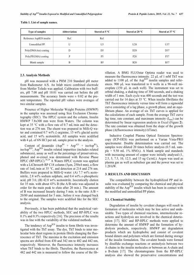
Stability of AspB28
Insulin Exposed to Modified and Unmodified Polypropylene Protein & Peptide Letters, 2015, Vol. 22, No. 7 637
2.3. Analysis Methods
pH was measured with a PHM 210 Standard pH meter from Radiometer A/S. An Inlab micro combined electrode from Mettler Toledo was applied. Calibration with two buff-ers, pH 7.00 and pH 10.01 was carried out before the pH measurements. The accuracy limits were ± 0.02 at the pre-sent temperature. The reported pH values were averages of two similar samples.
Presence of Higher Molecular Weight Proteins (HMWP) in the samples was assessed using Size Exclusion Chroma-tography (SEC). The HPLC system and the column, Insulin HMWP 7.8x300 mm were from Waters. The column was kept at 35 °C with a flow rate of 0.7 mL/min and the detec-tion was at 276 nm. The eluent was prepared in Milli-Q wa-ter and contained 0.7 wt% L-arginine, 15 wt% glacial acetic acid, and 15 wt% acetonitrile. All samples were acidified with 4 �L of 6N HCl per mL sample prior to the analysis.
Content of desamido (AspB3
+ AspA21
+ isoAspB3
), isoAsp
B28, Asp
B28 insulin related impurities (includes related
substances), assay as well as the percentage of preservatives, phenol and m-cresol was determined with Reverse Phase HPLC (RP-HPLC).
28,29 A Waters HPLC system was applied
with a LiChrosorb RP C18 column (5�m, 250x4 mm), a flow rate of 1mL/min at 35 °C, and detection at 214 and 276 nm. Buffers were prepared in Milli-Q water: (A) 7.7 wt% aceto-nitrile, 2.8 wt% sodium sulphate, and 0.4 wt% o-phosphoric acid, pH 3.6; (B) 42.8 wt% acetonitrile. Isocratically elution for 35 min. with about 43% B (the A/B ratio was adjusted in order for the main peak to elute after 20 min.). The amount of B was increased linearly during 5 min. to the ratio A/B = 20/80 and maintained for 5 min.; before it was changed back to the original. The samples were acidified like for the SEC analysis.
Previously, it has been published that the analytical vari-ability of the two HPLC methods, SEC and RP-HPLC was 0.1% and 0.3% respectively [16]. The precision of the results was in line with the variability of the validated methods.
The tendency of AspB28
insulin to form fibrils was inves-tigated with the ThT assay. The dye, ThT binds to inter mo-lecular beta sheet regions in protein fibrils changing the fluo-rescence of ThT. The maxima in the excitation and emission spectra are shifted from 430 and 342 nm to 482 and 442 nm, respectively. Moreover, the fluorescence intensity increases when ThT binds to the fibrils. Therefore, the fluorescence at 482 and 442 nm is measured to follow the course of the fib-
rillation. A BMG FLUOstar Optima reader was used to measure the fluorescence intensity. 22 �L of 1 mM ThT was added to 1100 �L of the Asp
B28 insulin samples and refer-
ences. 900 �L was transferred to 6 wells in a 96-well mi-croplate (150 �L in each well). The instrument was set to orbital shaking, a shaking time of 300 seconds, and a shaking width of 1 mm. Each cycle was 400 seconds and the test was carried out for 14 days at 35 °C. When insulin fibrillates the ThT fluorescence intensity versus time will form a sigmoidal curve consisting of a lag phase, a growth phase, and an equi-librium phase. An average of six ThT curves is applied for the calculations of each sample. From the average ThT curve lag time, rate constant, and maximum intensity (Imax) can be determined by linear regression analysis in Excel (Figure 2). The rate constant was obtained from the slope of the growth phase (�(fluorescence intensity)/�Time).
Inductive Coupled Plasma Optical Emission Spectros-copy (ICP-OES) was performed on a Varian Vista-PRO spectrometer. Double determination was carried out. The samples were diluted 20 times before analysis (0.5 mL sam-ple + 9.50 mL 1% HNO3). A blank sample and standards with increasing amount of copper were initially analysed (1, 2.5, 5, 7.5, 10, 12.5, and 15 ng Cu/mL). Argon was used as plasma gas as well as nebuliser gas and the power was set to 1.20 kW.
3. RESULTS AND DISCUSSION
The compatibility between the hydrophilized PP and in-sulin was evaluated by comparing the chemical and physical stability of the Asp
B28 insulin which has been in contact with
the modified and unmodified PP plates.
3.1. Chemical Stability
Degradation of insulin by covalent changes will result in formation of molecules which may be less active and unde-sirable. Two types of chemical reactions, intermolecular re-actions and hydrolysis are involved in the chemical deterio-ration [17]. SEC and RP-HPLC methods were applied to determine the amount of HMWP and the formation of hy-drolysis products, respectively. HMWP are degradation products which are hydrophobic and consist of covalent bound dimers and polymers which are formed during storage of the insulin formulation. The covalent bonds were formed by disulfide exchange reactions or aminolysis between two A-chains in the insulin molecules or between an A-chain and a B-chain [17]. The chromatograms from the RP-HPLC analysis also showed the preservative concentrations and
Table 1. List of sample names.
Type of samples Abbreviation Stored at 5 °C Stored at 20 °C Stored at 37 °C
Reference AspB28 insulin Ref. Ref.
Unmodified PP U U5 U20 U37
Poly(DMAAm) coating D D5 D20 D37
Poly(PEGMA) coating P P5 P20 P37
Blank sample B B5 B20 B37

638 Protein & Peptide Letters, 2015, Vol. 22, No. 7 Fristrup et al.
assay of insulin in the samples. Each data point on the curves from the HPLC analyses was an average of two samples. However, the standard deviation was not included as the numbers from the two samples showed great resemblance as expected. In the following figures the line combining the measured values should serve as a guide to the eye and does not necessarily reflect values between the reported values. In RP-HPLC the insulin dimers and some oxidation products [28,29]
were designated as Asp
B28 insulin related impurities
(Figure 3). In order to highlight the content of AspB28
insulin related impurities in the different samples only the data for the accelerated conditions (37 °C) and the reference are shown. The data observed at 5 and 20 °C have the same trend. PP with the poly(DMAAm) coating resulted in the highest content of Asp
B28 insulin related impurities. The
samples with poly(PEGMA) coated PP contained a lower amount of Asp
B28 insulin related impurities than the samples
with unmodified PP. The observed improvement is expected to be predictive of long term stability at 5 and 20 °C. There-fore, poly(PEGMA) coating of PP surfaces in primary pack-aging materials for Asp
B28 insulin is expected to have a pro-
nounced positive effect on the AspB28
insulin stability.
A decrease in the content of phenol is observed in the samples exposed to poly(DMAAm) coating (Figure 4). This can either be explained by depletion through adsorption to the poly(DMAAm) coating or by degradation of phenol due to the coating. In any case, it can be concluded that the poly(DMAAm) coating has a high affinity to preservatives in the drug formulation. Asp
B28 insulin will despite its mono-
meric character form hexamers in the presence of zinc ions and phenol or phenol-like molecules [30]. Insulin binds phe-nol and the compact and stable R6 hexamer is formed. If less phenol is present the less stable T6 will be formed. With the experimental conditions reported by Derewenda et al. [31], it was concluded that the phenol concentration had an influence on the physical stability. However, the phenol con-centration required for stabilizing the R6 hexamer [31] is lower than the phenol concentration in the present formula-tion as phenol here also serves as a preservative. Neverthe-less, it can not be ruled out that the shift in the phenol con-centration observed in samples exposed to the
poly(DMAAm) coating may have an effect on the physical stability of Asp
B28 insulin. Insulin degrades relatively fast
below pH 5 and above pH 8. The optimum pH range for in-sulin was 6-7. At acidic pH values deamidation at residue A21 and formation of covalent insulin dimers will dominate whereas alkaline pH values will result in disulfide reactions. Formation of covalent insulin dimers and oligomers has an optimum around pH 4 and above pH 9 an accelerated forma-tion of covalent oligomers and polymers was observed due to disulfide interchange reactions. Hydrolysis of insulin has a minimum at pH 6.5 [17]. The increase in pH for Asp
B28 insu-
lin which has been in contact with the poly(DMAAm) coat-ing (Figure 6) is consistent with increase in Asp
B28 insulin
related impurities. The content of AspB28
insulin deamidation products (Asp
B3 + Asp
A21 + isoAsp
B3, Figure 5) was also
higher when it was exposed to poly(DMAAm).
The observation confirmed that hydrolysis of insulin will increase if pH is increased from 7.35 to above 8.
The in-
crease in the pH value which was observed in the poly(DMAAm) samples might also contribute to stabiliza-tion of Asp
B28 insulin. Changes in pH can be due to leach-
ables. Analysis with ICP-OES showed that AspB28
insulin exposed to the poly(DMAAm) coating and stored at 37 °C for 20 weeks contained 7.2 �M copper (0.46 �g/mL) whereas the potential copper content in other samples was below the detection limit of 0.8 �M (0.05 �g/mL). The cop-per contamination most likely originates from the catalyst, which is applied for the SI-ATRP. Divalent metal ions are known to be capable of oxidizing insulin and increase pH. A spread of ± 0.3 in the pH values was measured for some samples containing the poly(DMAAAm) coating and stored at 37 °C which can be due to heterogeneous distribution of the coating.
3.2. Physical Stability
When insulin is exposed to e.g. hydrophobic surfaces, heat or shear forces, it can undergo conformational changes which will result in aggregation and formation of insulin fibrils [17].
To investigate the tendency of insulin to fibrillate
the ThT assay is used. Insulin which has been exposed to
Figure 2. Determination of lag time, rate constant, and maximum intensity (Imax).
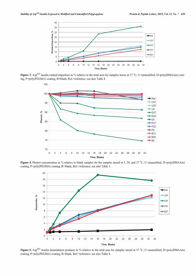
Stability of AspB28
Insulin Exposed to Modified and Unmodified Polypropylene Protein & Peptide Letters, 2015, Vol. 22, No. 7 639
Figure 3. AspB28
insulin related impurities in % relative to the total area for samples stores at 37 oC; U=unmodified, D=poly(DMAAm) coat-
ing, P=poly(PEGMA) coating, B=blank, Ref.=reference; see also Table 1.
Figure 4. Phenol concentration in % relative to blank samples for the samples stored at 5, 20, and 37 oC; U=unmodified, D=poly(DMAAm)
coating, P=poly(PEGMA) coating, B=blank, Ref.=reference; see also Table 1.
Figure 5. AspB28
insulin deamidation products in % relative to the total area for samples stored at 37 oC; U=unmodified, D=poly(DMAAm)
coating, P=poly(PEGMA) coating, B=blank, Ref.=reference; see also Table 1.
0
5
10
15
20
25
30
35
40
0 2 4 6 8 10 12 14 16 18 20 22 24 26 28 30 32 34
Rel
ated
Impu
ritie
s, %
Time, Weeks
Ref.
U37
D37
P37
B37
70
75
80
85
90
95
100
105
0 2 4 6 8 10 12 14 16 18 20 22 24 26 28 30 32 34
Time, Weeks
Phe
nol,
%
Ref.U37U20U5D37D20D5P37P20P5B37B20B5
0
2
4
6
8
10
12
14
16
18
20
0 2 4 6 8 10 12 14 16 18 20 22 24 26 28 30 32 34
Des
amid
o, %
Time, Weeks
Ref.
U37
D37
P37
B37

640 Protein & Peptide Letters, 2015, Vol. 22, No. 7 Fristrup et al.
Figure 6. pH for all samples stored at 5, 20, 37 oC; U=unmodified, D=poly(DMAAm) coating, P=poly(PEGMA) coating, B=blank,
Ref.=reference; see also Table 1.
modified or unmodified PP was compared with reference insulin and blank samples. Insulin and the dye ThT was transferred to 96-well microplates and placed in fluorescence plate-reader. ThT will bind to the insulin fibrils and its exci-tation and emission spectra maxima at 342 and 430 nm, re-spectively, will be shifted to new maxima at 442 and 482 nm.
AspB28
insulin exposed to the poly(DMAAm) coating for 16 and 33 weeks at 37 °C (D37) did not reach a Imax value and it was impossible to determine the rate constant within the days of testing on the plate-reader. The pH values were above 7.3 for those samples; therefore, the ThT dye might undergo hydroxylation during the time of the measurements [32]. More dye was added to the wells containing D37 which have been stored for 33 weeks. The fluorescence intensity for the D37 samples after 33 weeks was around 1000 a.u. (the initial value for the other 37 °C samples was about 300 and 100 a.u. for the rest) when the test was initiated and it did not increase significantly for an extended period of 21 days. 4 �L of ThT were added to each well three times dur-ing this time period; however, only minor increases in the fluorescence intensity were observed. Therefore, the results from the D37 samples have been omitted in Fig. 7 to Fig. 8. Some reasons have already been described for the observed increase in physical stability due to the poly(DMAAm) coat-ing and they might interact. Copper from the catalyst has already been mentioned and it is also expected to have a sta-bilizing effect on the physical stability. Studies with amy-loid-b (Ab) peptides have shown that Cu(II) inhibits Ab42 fibrillation and initiate formation of non-fibrillar Ab42 aggre-gates. After incubation for a week amyloid fibrils were de-tected in samples with Ab42 aggregates [33]. If the fibrilla-tion process is slow other studies have shown that metal ions can accelerate the fibril formation by assembly between pep-tides and metal-induced aggregates [34]. The growth of fi-brils is fast for Asp
B28 insulin; therefore, the copper ions
were expected to inhibit fibrillation by lowering the concen-
tration of free insulin, which was not aggregated insulin. In order to give an overview of the results obtained, the data for analyses carried out on the samples stored at 37 °C has been collected in Table 2.
The rate constants determined from the ThT curves for the samples containing unmodified PP, poly(PEGMA) and Poly(DMAAm) coated PP at the accelerated conditions (37 °C) were shown in Table 2. The Asp
B28 insulin exposed to
the poly(PEGMA) coating had statistically significant lower fibrillation rate constant than the other samples including the blank. Therefore, the physical stability of the Asp
B28 insulin
in contact with poly(PEGMA) was improved compared with unmodified PP and siliconized glass.
Correlations between the rate constant in the ThT assay and Asp
B28 insulin related impurities and HMWP were illus-
trated in Fig. 7 and Fig. 8, respectively. The three data points for each type of sample represent the three different times (10, 16, and 33 weeks) where samples were taken for the ThT assay. The rate constant decreases whereas the content of Asp
B28 insulin related impurities and HMWP increase
over time. If the rate constant was replaced with Imax similar correlations were observed. The results for the samples stored at 5 °C have been omitted to elucidate the coherence between chemical and physical stability; however, they were located between the reference and the 20 °C samples.
When the rate constant decreased the physical stability was improved as the fibril formation was slowed down (Fig-ures 7 and 8). Inverse correlations between the content of Asp
B28 insulin related impurities or HMWP and the tendency
to fibrillate were observed. Increased physical stability of Asp
B28 insulin due to formation of insulin dimers, oligomers,
and polymers has previously been reported by Senstius et al. [16]. The observations with the lower rate constants for a higher content of Asp
B28 insulin related impurities and
HMWP fit in well with the theory about the correlation be-tween chemical and physical stability. Samples with the
7.2
7.4
7.6
7.8
8.0
8.2
8.4
0 2 4 6 8 10 12 14 16 18 20 22 24 26 28 30 32 34
Time, Weeks
pH
Ref.U37U20U5D37D20D5P37P20P5B37B20B5

Stability of AspB28
Insulin Exposed to Modified and Unmodified Polypropylene Protein & Peptide Letters, 2015, Vol. 22, No. 7 641
poly(DMAAm) contained less insulin polymer but more dimer than the other samples kept at the same temperature. Related impurities contain the different covalent bound insu-lin dimers; therefore, the data for Asp
B28 insulin exposed to
poly(DMAAm) at 20 °C (D20) was separated from the other 20 °C samples in Fig. 7. In Fig. 8 insulin dimers and poly-mers were added up in HMWP. Thus D20 did not differ from the other 20 °C samples. Moreover, the 37 °C samples seem to indicate a slight improvement in the physical stabil-ity due to the poly(PEGMA) coating without jeopardizing the chemical stability as related impurities and HMWP were not higher than for the unmodified PP.
4. CONCLUSIONS
In general, AspB28
insulin related impurities and HMWP were observed to correlate inversely with the increased physical stability. Cause and effect have not been clarified; however, the observations pointed towards coherence be-
tween the chemical and physical stability of AspB28
insulin. The poly(DMAAm) coating showed a high affinity to the preservatives in consequence a lower phenol concentration was observed which cannot be excluded to have an effect on the physical stability. Moreover, The poly(DMAAm) re-sulted in the highest content of Asp
B28 insulin related impuri-
ties. The increase in pH was consistent with the increase in Asp
B28 insulin related impurities due to poly(DMAAm). 7.2
�M copper from the catalyst was detected in the samples with poly(DMAAm) coated PP and the copper might oxidize insulin and increase pH. It can not be ruled out that the cop-per from the catalyst will also contribute to improved physi-cal stability as Cu(II) is expected to inhibit fibrillation for Asp
B28 insulin. Finally, the poly(DMAAm) samples con-
tained less AspB28
insulin polymer but more dimer than the other samples kept at the same temperature.
The poly(PEGMA) coating resulted in improved stability of Asp
B28 insulin compared to unmodified PP and the
Table 2. Data from the analyses of AspB28
insulin exposed to U37=unmodified PP, and D37=poly(DMAAm) coated PP,
P37=poly(PEGMA) coated PP, B37=blank sample (pure insulin solution); the samples have been stored at 37°C for 33
weeks; see also Table 1.
U37 D37 P37 B37
AspB28 related impurities, % 16.3 36.2 14.8 12.5
HMWP, % 5.6 3.6 5.5 4.8
Fibrillation rate constant,
1/hours 76±3 -a 62±3 224±47
Phenol, % 99 77 100 101
pH 7.30 8.04 7.30 7.31
Copperb, �M < 0.8 7.2 < 0.8 < 0.8
a Fibrillation was observed within 21 days
b Acuracy ±0.8 �M
Figure 7. The rate constant from the ThT assay versus AspB28 insulin related impurities in % relative to the total area for the three sampling
times 10, 16, and 33 weeks; U=unmodified, D=poly(DMAAm) coating, P=poly(PEGMA) coating, B=blank, Ref.=reference; see also
Table 1.
0
200
400
600
800
1000
1200
1400
1600
1800
0 5 10 15 20
Rat
e co
nsta
nt, 1
/hou
rs
Related impurities, %
Ref.U37U20D20P37P20B37B20

642 Protein & Peptide Letters, 2015, Vol. 22, No. 7 Fristrup et al.
poly(DMAAm) coating. The improvement of the stability was especially evident for the samples stored at 37 °C when the samples have been stored for eight months. The data ob-served for the accelerated conditions (37 °C) have the same trend as data observed at 5 and 20 °C. The observed im-provement may therefore be expected to be predictive of long term stability at 5 and 20 °C. Poly(PEGMA) coating of PP surfaces in primary packaging materials for Asp
B28 insu-
lin is thus expected to have a pronounced positive effect on the Asp
B28 insulin stability. Table 3 summarizes the influ-
ence of the coatings on the results compared to the unmodi-fied PP.
Considerations like sterilization and permeability will have to be considered before PP coated with poly(PEGMA) can be applied in a stability study which compares the po-lymeric material with siliconized glass. However, this study has proven that a material like poly(PEGMA) coated PP has the possibility of replacing glass for storage of a drug prod-uct formulation.
CONFLICT OF INTEREST
The authors confirm that this article content has no con-flicts of interest.
ACKNOWLEDGEMENTS
CJF acknowledges the Technical University of Denmark, Novo Nordisk A/S, and the Danish Agency for Science Technology and Innovation for financial support. Further-more, we thank Monika Butrimaité for the modification with PEGMA. Dorrit Eggert Larsen and Kirsten Larsen from
Novo Nordisk A/S are acknowledged for assistance with the HPLC analyses. Anne Ahrensberg Jensen from Novo Nord-isk A/S is acknowledged for training in the ThT assay. Nina Lorentzen, Lisa Falk Nielsen, and Annette Behrens also from Novo Nordisk A/S are thanked for carrying out the ICP-OES analysis. The manuscript was written through contributions of all authors. All authors have given approval to the final version of the manuscript.
REFERENCES
[1] Kokubun, S.; Ratcliffe, I.; Williams, P.A. Synthesis, characteriza-
tion and self-assembly of biosurfactants based on hydrophobically modified insulins. Biomacromolecules, 2013, 14, 2830-2836.
[2] Sarmento, B.; Ribeiro, A.; Veiga, F.; Ferreira, D.; Neufeld, R. Oral bioavailability of insulin in polysaccharide nanoparticles. Biomac-
romolecules, 2007, 8, 3054-3060. [3] Agrawal, A. K.; Harde, H.; Thanki, K.; Jain, S. Improved stability
and antidiabetic potential of insulin containing folic acid function-alized polymer stabilized multilayered liposomes following oral
administration. Biomacromolecules, 2014, 15, 350-360. [4] Lee, J.S.; Um, E.; Park, J.K.; Park, C.B. Microfluidic self-assembly
of insulin monomers into amyloid fibrils on a solid surface. Lang-muir, 2008, 24, 7068-7071.
[5] Nayak, A.; Dutta, A.K.; Belfort, G. Surface-enhanced nucleation of insulin amyloid fibrillation. Biochem. Biophys. Res. Commun.,
2008, 369, 303-307. [6] Thurow, H.; Geisen, K. Stabilisation of dissolved proteins against
denaturation at hydrophobic interfaces. Diabetologia, 1984, 27, 212-218.
[7] Smith, M.I.; Sharp, J.S.; Roberts, C.J. Nucleation and growth of insulin fibrils in bulk solution and at hydrophobic polystyrene sur-
faces. Biophys. J., 2007, 93, 2143-2151. [8] Zhu, M.; Souillac, P.O.; Ionescu-Zanetti, C.; Carter, S.A.; Fink,
A.L. Surface-catalyzed amyloid fibril formation. J. Biol. Chem., 2002, 277, 50914-50922.
Figure 8. The rate constant from the ThT assay versus HMWP in per cent relative to the total area for the three sampling times 10, 16, and
33 weeks; U=unmodified, D=poly(DMAAm) coating, P=poly(PEGMA) coating, B=blank, and Ref.=reference; see also Table 1.
Table 3. Results for AspB28
insulin after exposure to the coated PP compared with unmodified PP; green is a favorable result
whereas red is unfavorable; the arrows indicate whether the value increases (�), decreases (�) or stays at the same level (�)
compared to samples exposed to unmodified PP.
Coating AspB28
insulin related impurities HMWP Fibrillation rate constant Phenol pH Copper
Poly(DMAAm) � � � � � �
Poly(PEGMA) � � � � � �
0
200
400
600
800
1000
1200
1400
1600
1800
2000
2200
0 1 2 3 4 5 6
Rat
e co
nsta
nt, 1
/hou
rs
HMWP, %
Ref.U37U20D20P37P20B37B20
Stability of AspB28
Insulin Exposed to Modified and Unmodified Polypropylene Protein & Peptide Letters, 2015, Vol. 22, No. 7 643
[9] Frank, B.H.; Pekar, A.H.; Veros, A.J. Insulin and proinsulin con-
formation in solution. Diabetes, 1972, 21, 486-491. [10] Sluzky, V.; Tamada, J.A.; Klibanov, A.M.; Langer, R. Kinetics of
insulin aggregation in aqueous-solutions upon agitation in the pres-ence of hydrophobic surfaces. Proc. Natl. Acad. Sci. USA, 1991,
88, 9377-9381. [11] Brange, J.; Andersen, L.; Laursen, E.D.; Meyn, G.; Rasmussen, E.
Toward understanding insulin fibrillation. J. Pharm. Sci., 1997, 86, 517-525.
[12] Nielsen, L.; Khurana, R.; Coats, A.; Frokjaer, S.; Brange, J.; Vyas, S.; Uversky, V.N.; Fink, A.L. Effect of environmental factors on
the kinetics of insulin fibril formation: elucidation of the molecular mechanism. Biochemistry, 2001, 40, 6036-6046.
[13] Vestergaard, B.; Groenning, M.; Roessle, M.; Kastrup, J.S.; van de Weert, M.; Flink, J.; Frokjaer, S.; Gajhede, M.; Svergun, D.I. A
helical structural nucleus in the primary elongating unit of insulin amyloid fibrils. PLoS Biol., 2007, 5, 1089-1097.
[14] Arnebrant, T.; Nylander, T. Adsorption of insulin on metal-surfaces in relation to association behavior. J. Colloid Interface Sci., 1988,
122, 557-566. [15] Nilsson, P. Nylander, T.; Havelund, S. Adsorption of insulin on
solid surfaces in relation to the surface-properties of the monomeric and oligomeric forms. J. Colloid Interface Sci., 1991, 144, 145-
152. [16] Senstius, J.; Poulsen, C.; Hvass, A. Comparison of in vitro stability
for insulin aspart and insulin glulisine during simulated use in infu-sion pumps. Diabetes Technol. Ther., 2007, 9, 517-521.
[17] Brange, J. Stability of Insulin – Studies on the physical and chemi-cal stability of insulin in pharmaceutical formulation; Kluwer Aca-
demic Publishers: Boston, 1994. [18] ISO 10993-Biological evaluation of medical devices-Part 1:
Evaluation and testing within a risk management process 4. edition 2009-11-05.
[19] Fristrup, C.J.; Jankova, K.; Hvilsted, S. Surface-initiated atom transfer radical polymerization – a technique to develop biofunc-
tional coatings. Soft Matter, 2009, 5, 4623-4634. [20] Fristrup, C.J., Jankova, K.; Hvilsted, S. Hydrophilization of
poly(ether ether ketone) films by surface-initiated atom transfer radical polymerization. Polym. Chem., 2010, 1, 1696-1701.
[21] Huang, J.; Murata, H.; Koepsel, R.R.; Rusell, A.J.; Matyjaszewski, K. Antibacterial polypropylene via surface-initiated atom transfer
radical polymerization. Biomacromolecules, 2007, 8, 1396-1399. [22] Fristrup, C.J.; Jankova, K.; Eskimergen, R.; Bukrinsky, J.T.; Hvil-
sted, S. Protein repellent hydrophilic grafts prepared by surface-
initiated atom transfer radical polymerization from polypropylene.
Polym. Chem., 2012, 3, 198-203. [23] Elbert, D.L.; Hubbell, J.A. Surface treatments of polymers for
biocompatibility. Annu. Rev. Mater. Sci., 1996, 26, 365-394. [24] Lee, J.H.; Lee, H.B.; Andrade, J.D. Blood compatibility of poly-
ethylene oxide surfaces. Prog. Polym. Sci., 1995, 20, 1043-1079. [25] Lutz, J.F. Polymerization of oligo(ethylene glycol) (meth)acrylates:
Toward new generations of smart biocompatible materials. J. Po-lym. Sci. Part A: Polym. Chem., 2008, 46, 3459-3470.
[26] Malmsten, M.; Emoto, K.; Van Alstine, J.M. Effect of chain den-sity on inhibition of protein adsorption by poly(ethylene glycol)
based coatings. J. Colloid Interface Sci., 1998, 202, 507-517. [27] Coad, B.R.; Steels, B.M; Kizhakkedathu, J.N.; Brooks, D.E.; Hay-
nes, C.A. The influence of grafted polymer architecture and fluid hydrodynamics on protein separation by entropic interaction chro-
matography. Biotechnol. Bioeng., 2007, 97, 574-587. [28] Hvass, A.; Hach, M.; Jars, M.U. Complementary analytical HPLC
methods for insulin-related degradation products. American Bio-tech. Lab., 2003, 21, 8-12.
[29] Jars, M.U.; Hvass, A.; Waaben, D. Insulin aspart (AspB28 human insulin) derivatives formed in pharmaceutical solutions. Pharm.
Res., 2002, 19, 621-628. [30] Whittingham, J.L.; Edwards, D.J.; Antson, A.A.; Clarkson, J.M.;
Dodson, G.G. Interactions of phenol and m-cresol in thee insulin hexamer, and their effect on the association properties of B28 Pro
� Asp insulin analogues. Biochemistry, 1998, 37, 11516-11523. [31] Derewenda, U.; Derewenda, Z.; Dodson, E.J.; Reynolds, C.D.;
Smith, G.D.; Sparks, C.; Swenson, D. Phenol stabilizes more helix in a new symmetrical zinc insulin hexamer. Nature, 1989, 338,
594-596. [32] Fodera, V.; Groenning, M.; Vetri; V.; Librizzi, F.; Spagnolo, S.;
Cornett, C.; Olsen, L.; van de Weert, M.; Leone, M. Thioflavin T hydroxylation at basic pH and its effect on amyloid fibril detection.
J. Phys. Chem. B, 2008, 112, 15174-15181. [33] Tougu, V.; Karafin, A.; Zovo, K.; Chung, R.S.; Howells, C.; West,
A.K.; Palumaa, P. Zn(II)- and Cu(II)-induced non-fibrillar aggre-gates of amyloid-� (1-42) peptide are transformed to amyloid fi-
brils, both spontaneously and under the influence of metal chela-tors. J. Neurochem., 2009, 110, 1784-1795.
[34] Uversky, V.; Li, J.; Fink, A.L. Metal-triggered structural transfor-mations, aggregation, and fibrillation of human-synuclein. J. Biol.
Chem., 2001, 276, 44284-44296.
Received: January 27, 2015 Revised: May 18, 2015 Accepted: May 23, 2015


Polymers for Pharmaceutical Packaging and Delivery Systems
Charlotte Juel Fristrup PhD Thesis
2010
Polymers for Pharmaceutical Packaging and Delivery Systems
Charlotte Juel Fristrup PhD Thesis
2010 DTU Chemical Engineering Department of Chemical and Biochemical Engineering
The Danish Polymer CentreDepartment of Chemical and Biochemical EngineeringTechnical University of DenmarkSøltofts Plads, Building 227DK – 2800 Kgs. LyngbyDenmark Phone: +45 45 25 68 01Web: kt.dtu.dk/english/Research/DPC
Polymers for P
harmaceutical Packaging and D
elivery Systems
Charlotte Juel Fristrup
2010