Embed Size (px)
Citation preview

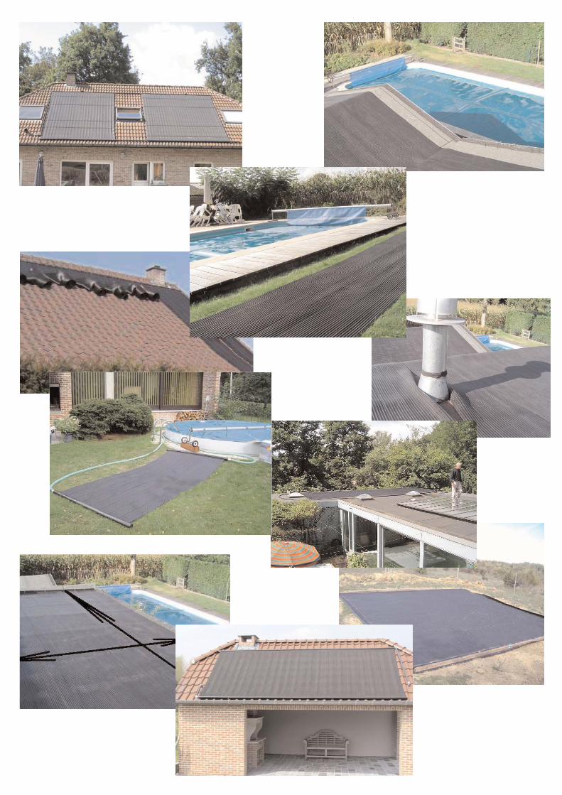
Poolsolar Installation Guide
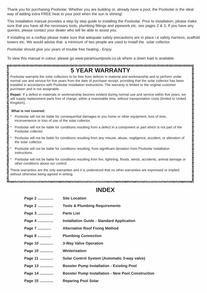
INDEXPage 2 ............... Site Location
Page 2 ............... Tools & Plumbing Requirements
Page 3 ............... Parts List
Page 4 ............... Installation Guide - Standard Application
Page 7 ............. Alternative Roof Fixing Method
Page 8 ............. Plumbing Connection
Page 10 ............. 3-Way Valve Operation
Page 10 ............. Winterisation
Page 11 ............. Solar Control System (Automatic 3-way valve)
Page 13 ............. Booster Pump Installation - Existing Pool
Page 14 ............. Booster Pump Installation - New Pool Construction
Page 15 ............. Reparing Pool Solar
Thank you for purchasing Poolsolar. Whether you are building or, already have a pool, the Poolsolar is the idealway of adding extra FREE heat to your pool when the sun is shining!
This installation manual provides a step by step guide to installing the Poolsolar. Prior to installation, please makesure that you have all the necessary tools, plumbing fittings and pipework etc. see pages 2 & 3. If you have anyqueries, please contact your dealer who will be able to assist you.
If installing on a rooftop please make sure that adequate safety precautions are in place i.e safety harness, scaffoldtowers etc. We would advise that a minimum of two people are used to install the solar collector.
Poolsolar should give you years of trouble free heating - Enjoy.
To view this manual in colour, please go www.paramountpools.co.uk where a down load is available.
5 YEAR WARRANTYPoolsolar warrants the solar collectors to be free from defects in material and workmanship and to perform undernormal use and service for five years from the date of purchase receipt, providing that the solar collector has beeninstalled in accordance with Poolsolar installation instructions. The warranty is limited to the original customerpurchaser and is not assignable.Repair: If a defect in materials or workmanship beomes evident during normal use and service within five years, wewill supply replacement parts free of charge, within a reasonable time, without transportation costs (limited to UnitedKingdom).
What is not covered:* Poolsolar will not be liable for consequential damages to you home or other equipment, loss of time,
inconvenience or loss of use of the solar collector.
* Poolsolar will not be liable for conditions resulting from a defect in a component or part which is not part of the Poolsolar collector.
* Poolsolar will not be liable for conditions resulting from any misuse, abuse, negligence, accident, or alteration of the solar collector.
* Poolsolar will not be liable for conditions resulting, from significant deviation from Poolsolar installation instructions.
* Poolsolar will not be liable for conditions resulting from fire, lightning, floods, winds, accidents, animal damage or other conditions above our control.
These warranties are the only warranties and it is understood that no other warranties are expressed or impliedwithout otherwise being agreed in writing.

2
SITE LOCATION The Poolsolar solar collectors should be positioned facing the sun as much aspossible for a maximum efficiency, ideally 30 deg (above horizontal) facing South.
FILTRATION - MAXIMUM WORKING PRESSURE SHOULD NOT BE ABOVE 1.5 BAR (22 PSI)
A solar heat retention cover must be applied to swimming pool overnight and when the pool isnot in use to prevent heat loss.
If installing Poolsolar on a ground surface i.e. for small above ground or splasher type pools please beaware that Poolsolar is not designed for heavy foot traffic.
Make sure that all pipework to and from the solar collector can be drained for the winter period.
We would recommend the use of a time clock to automatically turn off the filtration system at night or by-pass the solar system. Alternatively, an automatic control system can be installed see page 11.
Please take sufficient safety precautions before working on a roof.
Prior to commencing installation we recommend that you have the following tools and accessoriesavailable:-
Tools:- Drill / Extruder Gun (for adhesive tubes) / Mini Wallpaper Roller / Screw Drivers / Hacksaw /Knife
Accessories:-
ABS/PVC Glue / 1.5" Pool Plumbing (not domestic waste pipe) / PTFE Tape
Manual or Automatic 3-way Valve
Vacuum Breaker- Air release valve (see page 9, step 12)
Roof Fixing Paste
White Spirit
2000mm x 60mm x 40mm Rigid Plastic Angle (available from your dealer) for support on pitched roofinstallations see page 2.
TOOLS AND PLUMBING REQUIREMENTS
90 deg. ELBOWP/TSOCKET
P/T SOCKETUNION
P/P SOCKETUNION
GLUE P.T.F.E TAPE 3m x 1.5” ABS PIPEY- SECTION
Automatic 3-Way Valve Manual 3-Way Valve VACUUM BREAKER(Model may vary)

3
PARTS LIST
To install Poolsolar onto a tiled roof you will need toattach L-shaped support angles to support the headers.
Plastic extrusion (H) are 2000 x 60 x 40 mm and areavailable from your pool dealer.
The L-shaped extrusion is supplied in 2.00 m lengths.Depending on the number of solar matts that you havepurchased you will need to apply enough extrusion tosupport the entire length of the headers (manifolds) topand bottom.
60
60mm
35mm
4mm
C31.5”
ThreadedPlug
C650mm - 1.5”
Adaptor(external)
C91.5”
ThreadedAdaptor
VacuumBreaker
C1350mm - 1.5”
Adaptor(internal)
C81.5”
ThreadedAdaptor
C12ReducingAdaptor
C12ReducingAdaptor
Pool Solar is supplied in a 4 or 5m kit boxes and contains all the necessary components for you to installa solar collector. In addition to this you wil require pool plumbing, roof adhesive and roof supports angles.
THE 5 m² BOX CONTAINS
- 3 units of solar collectors , each 33cm x 5m (5 m²) (and o-rings)- 10 metre nylon band to attach the headers and the absorber
- repair set and lubricant- two adaptors 50 mm in black ABS (C6 and C13)- two threaded adaptors 1 ½” in black ABS (C8 and C9)- two reducing sockets (C12) in black ABS- one threaded stop 1 ½” in black ABS - tie-wraps- installation guide
THE 4m² BOX CONTAINS
- 4 units of solar collectors, each 33cm x 3m (4 m²) (and o-rings)- 8 metre nylon band to attach the headers and the absorber
- repair set and lubricant- two adaptors 50 mm in black ABS (C6 and C13)- two threaded adaptors 1 ½” in black ABS (C8 and C9)- two reducing sockets (C12) in black ABS- one threaded stop 1 ½” in black ABS- tie-wraps - installation guide

4
STEP 1 Remove solar collectors (A) from thebox and place side by side in front of you with thenarrow part of the headers (B) to the left on aclean, flat surface. The header with the word"POOLSOLAR" must be visible. To check if thematting is the right way up, look at therubber that connects the absorber tubestogether; the material should archupwards (C).
INSTALLATION GUIDE
A
B
C
STEP 2 Join the polypropylene headers together applying aliberal amount of lubricant (provided) (D) to the header o-ring. Make sure that the o-ring doesn't bulge out afterclicking the headers together. Do not attempt to glue headerstogether.
D
STEP 3 Push the rubber edges (E) together so theabsorbers (EPDM matting) are united as a whole.
Tip - use a mini wallpaper roller to push the absorberstogether!
STEP 4 Before applying to the roof, make sure that thePoolsolar is the right way up. Small holes (F) are locatedalong the length of the absorbers to allow rain water to bedrained. Make sure that the holes are not blockedespecially on a flat roof. Do not use screws in theseholes to fix the absorbers.
E
F

5
NOTE. Steps 5-10 are for instructions for a tiled pitched roof. If theapplication is for a flat roof, exactly the same fixing method isused but on a level platform!
STEP 5 Roll up the entire collector (G), starting with the headersshowing "POOLSOLAR" (When they are unrolled on the roof youshould be able to see the word Poolsolar on the bottom manifoldsonly - see page 6 (M).
You are now ready to apply the Poolsolar onto roof structure.
* DO NOT ATTEMPT TO ROLL UP AND INSTALL MORE THAN ONE BOX AT A TIME ( 3 or 4 Collectors)
Make sure that where the Poolsolar is to be sited that you are able to attach the supply and returnplumbing pipes from the filtration (page 9). Adequate drainage is also required to remove rain water.
G
STEP 6 To install Poolsolar onto a tiled roof you will need toattach L-shaped support angles to support the headers see page 2
The L-shaped support angle is supplied in2.00 m lengths. Depending on the number ofsolar matts that you have purchased, cut andprepare the number of support extrusionrequired to support 90-100% of the headersthat will be located at the top of the roofstructure.
(H) Apply the support angles directly to the roof tiles using liberalamounts of ‘roof fixing adhesive paste’ (available from yourdealer).
Apply the 60mm width of the support angle to the tiles. Prior toapplying the adhesive make sure the tiles are dry, clean and dustfree. Leave for 24 hours for adhesive to fully cure.
Note: the adhesive is only as good as the surface it is applied to, therefore ensure the surface is free ofany loose foreign material.
H
IMPORTANT SAFETY NOTICE - It is paramount that adequate safety precautions are taken wheninstalling Poolsolar on a roof structure.
Support Angle cut towidth of Poolsolar Matt.
IF FOR ANY REASON YOU ARE NOT UNABLE TO USE AN ADHESIVE OR THE SUPPORT ANGLE -PLEASE GO TO PAGE 7 FOR ALTERNATIVE FIXING METHOD
60
60mm
35mm
4mm
60mm
‘L’-shape Support Angle

STEP 7 Position Poolsolar headers onto support angle(I). When the solar collectors are unrolled you should seethe word ‘POOLSOLAR’ on the bottom manifolds (M).
Using the electrical a tie-wraps provided (J) connect theheader to support angle every 66 cm.
I
66 cm 66 cm
J
Tie-wrap
Support Angle
STEP 8 Apply an adhesive (K) bead every 50 cm to theroof structure and unroll the Poolsolar matting. It is also agood idea to apply adhesive down the very edge of thematting (L).
50 cm
Adhesive Bead(s)
K L
M
STEP 9 Apply a support (M) angle to roofstructure to support the bottom headers.Secure headers to support angle with tie-wraps as per step 7.
STEP 10 Repeat above procedure to addadditional Poolsolar Matting.
Proceed to Page 8 for plumbingconnection.
Tie-wrap
6

7
ALTERNATIVE FIXING METHOD FOR ATILED ROOF
In the event that you are unable to use an adhesiveor support angle, nylon strapping (provided) can beused.
When the headers are to be positioned on the roof,you will need to remove certain roof tiles to obtain afixing onto the wood battons that support the rooftiles (O).
Fix 50 cm long nylon strips on the roof support battonevery 66 cm as per step 7 on page 6. Afterwards putthe roof tiles back in place so the nylon strips stickout 30 cm. Attach the nylon strips that stick out ofthe roof around the collector. Attach 2 tie-wraps toevery nylon strip.
Nylon strapping can also be used (horizontally)across the width of matting to secure it to the roofstructure (Q). Place straps 1 metre apart.
We highly recommend that adhesive is used wherepossible in addition to the nylon straps especially inhigh wind situations.
O
P
Q

8
Important Notes- Standard swimmingpool plumbing in Europe is generally suppliedin a metric dimension. However, in the UK allplumbing is supplied in an imperialmeasurement i.e. 1.5”
Poolsolar provide the correct plumbingadaptors that are enable you to connect toyour existing pipework.
In addition, you will need to purchase aselection of ABS or PVC plumbing fittings(including a 3-way valve) and pipework fromyour pool dealer, together with the correctadhesive.
Do not be tempted to use domestic waste pipe, it has not been manufactured to accept the water pressure that isproduced by your filtration. Never connect the Poolsolar to a mains water feed. Solar collectors have beendesigned to receive up to1.5 bar. Pool filtration is typically +/-1 bar.
The entire solar collector must be connected diagonally (R). The lowest point is where the water enters thecollector, the highest point is where the water exits. In each Poolsolar kit you find extra connecting parts, so youcan choose which method is suitable for your plumbing connection.
The extra supplied parts are made in ABS and can be glued with PVC-glue. The headers (B) are made in PP(polypropylene) and CANNOT BE GLUED.
To connect pipework to the Poolsolar you need to apply the correct adaptors to each corner -C6/C8/C9/C13 see picture below (S).
IN(lowestpoint)
OUT(Highest
point)
R
S
C31.5”
ThreadedPlug
C650mm - 1.5”
Adaptor(external)
C91.5”
ThreadedAdaptor
VacuumBreaker
C1350mm - 1.5”
Adaptor(internal)
C81.5”
ThreadedAdaptor
C12ReducingAdaptor
C12ReducingAdaptor
IMPORTANT: The part of the adaptor(s) that is connected directly to the headers must be connectedusing a lubricant only (provided).
PLUMBING CONNECTION

9
Manual3 - Way Ball
Valve
To Pool
Must be installed at thehighest point of thesolar collector
BACKWASH
FILTER
(Optional)Non-return Vavle
Filtration
WinterDrainage Plug(Threaded C3)
Close this port todirect water to solarmatting.
Vacuum Breaker(air release valve)
Optional - Automatic controlvalve available. Please seepage 11 for details
STEP 11 (T) Insert the correct plumbing adaptors to each corner C6-C8-C9-C13 (See page 8). Glue imperialreducing adaptors (C12) onto plumbing adaptor (C6 & C13) and cut to desired diameter. For all threaded fittings,apply PTFE. tape.
Lubricant
ABS/PVC Glue
STEP 12 Connect ABS/PVC 1.5” plumbing to Poolsolar as per diagram below. You will need to install a 3-wayvalve, this will enable you to direct the water flow to the heater and back to the pool. A vacuum breaker will also berequired on solar heating that is 4m or higher above ground level. Vacuum breakers are not required for low levelinstallations. Once all of the plumbing connections have been made, proceed to step 13.
For other installation methods using an additional booster pump please go to page 13
T
Insert1.5” Pipe
C6 or C1350mm - 1.5”
Adaptor
C6 or C1350mm - 1.5”
AdaptorConnect
1.25 or 1.5”Flexible Hose
C12
C12

STEP 13 To operate the Poolsolar system the water flow needs to be redirected to the solar collector using amanually operated 3-way valve.
To direct water flow to solar collector :- Point the handle on the 3-way valve to close the port that directs thewater back to the pool. The water flow will now pass through the solar collector and back to the pool.
To direct water flow to swimming pool only :- Point the handle to close the solar collector port when solarheating is not required. It important that the water is not fed to the collector in cold periods of weather or at night asthe solar collector will act like a giant radiator incurring great heat losses!
Your Poolsolar is now ready to start heating your pool.
Automatic 3-way valves are available to redirect the water flow automatically when cold periods arise. Pleasecontact your pool dealer or go to page 11 for installation details.
Water Flow
Closed Position
To Solar Collector
Water Flow
Handle
Closed Position
To Pool(Solar Collector)
by-passed
3-Way Valve Operation
Water flow to Solar Collector Water flow to pool, bypassing Solar Collector
Winterisation
1. Solar collector must be drained for the winter period.Remove C3 1.5” thread plug for water removal (U).
2. Drain supply and return pipework.
U C3 Threaded Plug
GENERAL MAINTENANCE
Poolsolar is manufactured from a very durable, tough EPDM rubber that is long lasting and will provide many yearsof trouble free heating. There is little maintenance apart from hosing down the solar collector to clean it throughoutthe season.
In the event that the you experience a leak in the solar collector a repair kit is provided. Go to page 15.
10

A Solar Control System will automatically turn the Poolsolar on and offdepending on the weather conditions using an automatic 3-way valve.
When the sun is shining the valve will direct the water flow to the solarcollector. When the temperature drops i.e. at night, the valve will directthe water flow back to the pool, bypassing the solar collector.Furthermore, it will stop the heating process when the desiredtemperature is reached.
Just as important, the valve will also prevent heated pool water fromgoing to the collector when there is no sun i.e. cloudy/night conditions,thus preventing any heat loss.
To install the Solar Control System, please do the followsteps 1-5
STEP 1 Install Solar Controller (temperature adjustment)on a wall using the two screw holders on the back of thesolar controller. Controller MUST BE INSTALLEDINDOORS.
STEP 2 The ‘Sun Temperature Sensor’ should be placed on topof the solar collector header (manifold). Use a ‘Tie-wrap’ to secureinto position. The ‘ Water Temperature Sensor’ is already locatedwithin the motorised valve.
Note. Sun Sensor cable can be extended to a maximum distance of 25 metres. Usethe same type cable i.e. 2 x core 0.34mm. Remove back plate on controller and insertdesired cable length. Make water proof joint with the existing cable that was originallysupplied.
Any electrical extension/adjustment should be carried out by a qualified electrician.
STEP 4 The 3- Way electronic motorised valve must be installed afterthe filter/pump (max bar 2.5). DO NOT INSTALL MOTORISED VALVEOUTSIDE.
It is recommended that three threaded socket unions & PT socket(available from your dealer) are used on two ports to enable easyremoval for maintenance etc. Use PTFE tape to seal all threaded joints.
Please see diagram on page 12 for plumbing connection and position.
SOLAR CONTROL SYSTEM (Automatic 3-Way Valve)
Solar Controller - front
Tie-wrap
Use Threaded SocketUnions to join plumbingonto 3-way valve!
Solar Controller - back
Twist Off
11

12
Automatic3 - Way Ball
Valve
To Pool
Must be installed at thehighest point of thesolar collector
BACKWASH
FILTER
(Optional)Non-return Vavle
WinterDrainage Plug(Threaded C3)
Vacuum Breaker(air release valve)
To Pool
STEP 5 The transformer (3 pin plug) needs to be placed into a 230 V. indoor wall outlet. In the event that themotorised valve is not going to be used for long periods of time i.e. over the winter period, remove the transformer.INSTALLATION IS NOW COMPLETED.
Operation Use the plus or minus arrows on the controller for setting the desired temperature. After 5 secondsthe desired temperature modus will stop and the actual pool water temperaturewill be displayed. In the event of a power failure, the system will automaticallyset the temperature on 25 degrees Celsius. Reset to desired temperature.
Maintenance The motorised valve requires no maintenance. However, ifyou experience leaking problems we suggest that you grease the inner side ofthe valve with a silicon lubricant. Remove the screw on the backside of themotor (1). Now remove both motor holders located on each side of the motor (2& 3). Unscrew both nuts which hold the white axis of the motor (4).
The nine screws holding the black top of the valve need also be removed. Afterthis you can start with lubricating the white and black o-ring inside the valve.
FAQTemperature is too high or too low or does not appear at all - Check all cable connections. Corrosion canmake a bad connection between cable and connector. Clean the copper ends of the cables and reconnect them.
The valve is leaking. Lubricate valve as described in ‘maintenance’ or replace valve lid o-ring.
Motor does not turn - Remove the transformer from the wall outlet. Continuously press the grey button located ontop of the motor and at the same time, turn the white axis a couple of times to the left and right side. This shouldfree/unlock the valve. This situation will arise if the valve is blocked by dirt or has not been used for long period.
Remove (3)Remove (2)
Remove (1)
Undo Nuts (4)

Must be installed at thehighest point of the solarcollector
BACKWASH
FILTER
Non-return Valve(with unions)
Filtration
WinterDrainage Plug(Threaded C3)
Vacuum Breaker(air release valve)
Supply 230V
Sun Sensor
ElectronicControlSensor
Pool
Main Drain
Skimmer
BallValve
BallValve
BallValve
Booster Pump
Supply 230VWater Sensor
Hot Water
Cold Water
Sun Sensor can beinstalled on either theplumbing line or solarmanifold. Make surethat it is exposed tosunlight.
Use a ‘Y’- Piecehere. Not 45 degElbow
Non-return Valve(with unions)
Use a ‘Y’- Piecehere. Not 45 degElbow
BOOSTER PUMP & SUN SENSOR - EXISTING POOL
Electronic Control Sensor monitors water andair temperature.
Water Sensor:- activates booster pump to increasewater temperature to desired set point.
Sun Sensor:- allow booster pump to work onlywhen the sun is heating solar collector.
In most situations your current filtration system has adequate pressure to supply water to the solar collector,normally up to 8m high. Your water flow pressure is very dependable on the power of the filtration pump, plumbingconfiguration etc.
If you are unsure about the necessity for a booster pump, try using your existing filtration first!
In the event that the desired place for your solar collector is on a high roof top in excess of 8 metres install abooster pump and sun sensor as per the diagram and instructions below.
The booster pump will require a water supply, we recommend utilising the Main Drain suction line. Please use the‘Y’-piece connections where indicated (prevents back pressure). Check with your pool dealer to make sure that youyou use the correct size booster pump.
Make sure the Electric Control System is only operational when the existing filtration is running!
For new pool installations we recommend that the booster pump is connected directly to the pool. Turn to page 14for details.
13
FILTRATION - MAXIMUMWORKING PRESSURESHOULD NOT BE ABOVE1.5 BAR (22 PSI)
Must be installed at thehighest point of the solarcollector
BACKWASH
FILTER
Filtration
WinterDrainage Plug(Threaded C3)
Vacuum Breaker(air release valve)
Supply 230V
Sun Sensor
ElectronicControlSensor
Pool
Main Drain
Skimmer
BallValve
BallValve
BallValve
Booster Pump
Supply 230V
Water Sensor
Hot Water
Cold Water
Sun Sensor can beinstalled on either theplumbing line or solarmanifold. Make surethat it is exposed tosunlight.
New suctionl i n e t o b einstalled intopool wall.
Non-return Valve(with unions)
Non-return Valve(with unions)
New supplyl i n e t o b einstalled intopool wall.
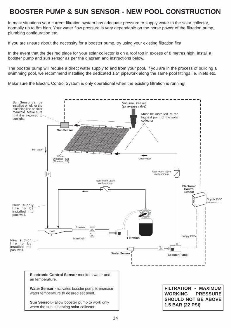
BOOSTER PUMP & SUN SENSOR - NEW POOL CONSTRUCTIONIn most situations your current filtration system has adequate pressure to supply water to the solar collector,normally up to 8m high. Your water flow pressure is very dependable on the horse power of the filtration pump,plumbing configuration etc.
If you are unsure about the necessity for a booster pump, try using your existing filtration first!
In the event that the desired place for your solar collector is on a roof top in excess of 8 metres high, install abooster pump and sun sensor as per the diagram and instructions below.
The booster pump will require a direct water supply to and from your pool. If you are in the process of building aswimming pool, we recommend installing the dedicated 1.5” pipework along the same pool fittings i.e. inlets etc.
Make sure the Electric Control System is only operational when the existing filtration is running!
Electronic Control Sensor monitors water andair temperature.
Water Sensor:- activates booster pump to increasewater temperature to desired set point.
Sun Sensor:- allow booster pump to work onlywhen the sun is heating solar collector.
14
FILTRATION - MAXIMUMWORKING PRESSURESHOULD NOT BE ABOVE1.5 BAR (22 PSI)

15
REPAIRING POOLSOLAR ‘HEADER’ ( MANIFOLD NOZZLE). You will need - Drill. 8 & 10mm Drill Bit, Scissors, Pliers, Plastic Repair Tube(s) (30mm x6mm - provided), Lubricant (provided). Tie- Wraps (provided).
In the event a nozzle is damaged or breaks off the header, carry out the following repairprocedure. Do not attempt to glue the nozzle(s) back into the header. The header is madefrom polypropylene and will not adhere.
REPAIRING POOLSOLAR
Step 1
The rubber that joins the tubes together to form the solarmatting needs to be cut away either side of the tubing(approximately 10cm) using a pair of scissors. Be careful notto cut the tubing!
Step 2
Remove and discard broken or damaged nozzle from rubbertubing. Drill an 8mm hole into the existing nozzle hole (onheader) to slightly enlarge it.
Tip - Once the 8mm hole has been drilled, lightly use a10mm drill to form a slight counter-sink. This will enable therubber tubing in step 4 to enter manifold much easier!
Step 3
Insert a plastic repair tube (30mm x 6mm - provided) usinglubricant into rubber tubing. Leave 10mm of rubberprotruding from the end of the plastic tube. 10mm
Drill a 8mm hole followedby a 10mm counters-sink
30mm x 6mmplastic insert

16
Step 4
Stretch the rubber tube with the insertedrepair nozzle and force it into the pre-drilledhole (step 2). Use pliers and lubricant to dothis.
The objective is to force the plastic repairtube down the rubber tubing and create aseal against the sides of the pre-drilledhole!
15mm of plastic repair tube should beinserted into the header.
The repair is now complete.
Force plastic repair tubeinto header.
Plastic repair tubepinches the rubbertubing against theheader creating a seal.
REPAIRING POOLSOLAR MATTING. You will need - Scissors, Pliers, Plastic Repair Tube(s) (30mm x 6mm - provided), Lubricant (provided). Tie- Wraps(provided).
In the event a tube is punctured, carry out the following repair procedure. Do not attempt to glue the tubing backtogether. The tubing is made from EPDM and cannot be glued.
Step 1
The rubber that joins the tubes together toform the solar matting needs to be cut awayeither side of the tubing (approximately 2cm)using a pair of scissors. Be careful not to cutthe tubing!
Step 2
Insert a plastic repair tube (30mm x 6mm -provided) using lubricant into rubber tubing.
Apply Tie- wrap to either sided of the plasticrepair tube.
The repair is now complete.
Tie-Wrap x 2
30mm Plasticinsert