Embed Size (px)
Citation preview

d@
Portable Aerosol Mobility Spectrometer MODEL 3300
Read this manual carefully and understand the warnings described in this manual before operating the product.
Keep this manual handy for future reference.
KANOMAX JAPAN, INC.
02002
14.06
Operation Manual
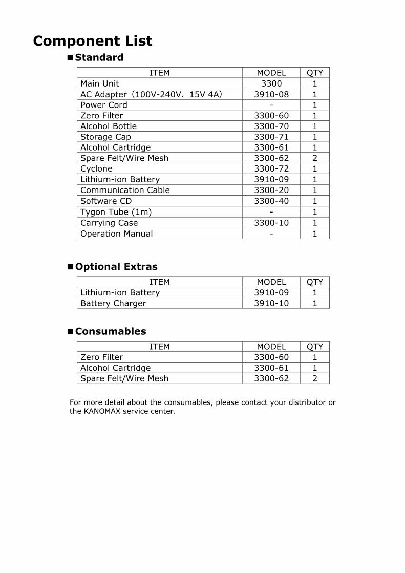
Component List ■Standard
ITEM MODEL QTY Main Unit 3300 1 AC Adapter(100V-240V、15V 4A) 3910-08 1 Power Cord - 1 Zero Filter 3300-60 1 Alcohol Bottle 3300-70 1 Storage Cap 3300-71 1 Alcohol Cartridge 3300-61 1 Spare Felt/Wire Mesh 3300-62 2 Cyclone 3300-72 1 Lithium-ion Battery 3910-09 1 Communication Cable 3300-20 1 Software CD 3300-40 1 Tygon Tube (1m) - 1 Carrying Case 3300-10 1 Operation Manual - 1
■Optional Extras ITEM MODEL QTY
Lithium-ion Battery 3910-09 1 Battery Charger 3910-10 1
■Consumables ITEM MODEL QTY
Zero Filter 3300-60 1 Alcohol Cartridge 3300-61 1 Spare Felt/Wire Mesh 3300-62 2
For more detail about the consumables, please contact your distributor or the KANOMAX service center.
About the Laser i
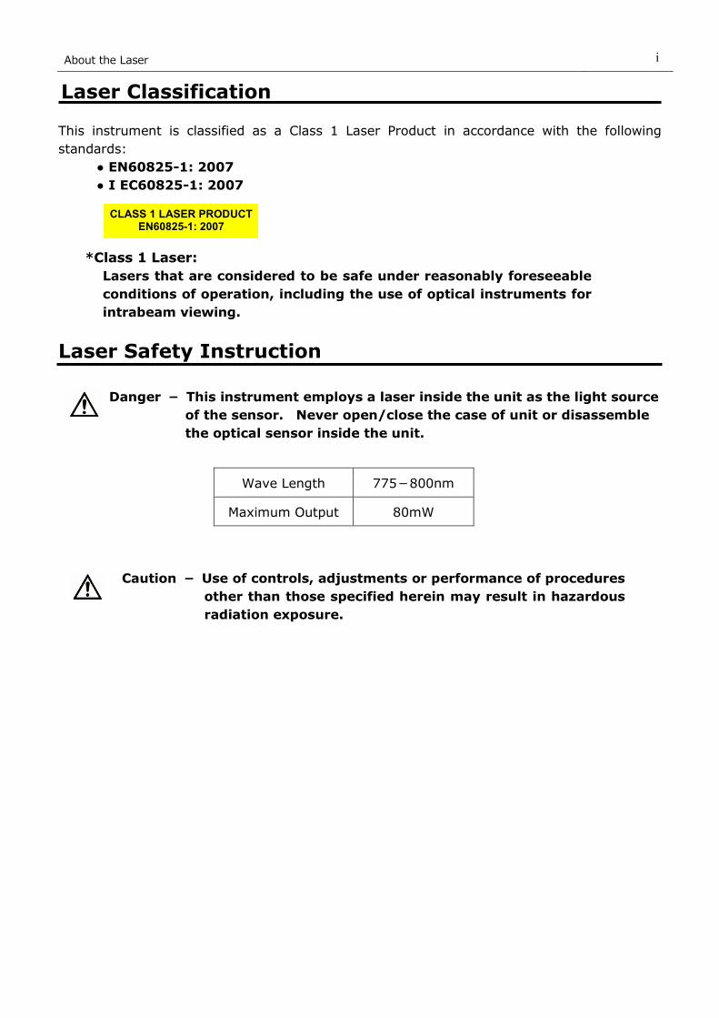
Laser Classification This instrument is classified as a Class 1 Laser Product in accordance with the following standards:
● EN60825-1: 2007 ● I EC60825-1: 2007
*Class 1 Laser:
Lasers that are considered to be safe under reasonably foreseeable conditions of operation, including the use of optical instruments for intrabeam viewing.
Laser Safety Instruction
Danger - This instrument employs a laser inside the unit as the light source of the sensor. Never open/close the case of unit or disassemble the optical sensor inside the unit.
Caution - Use of controls, adjustments or performance of procedures
other than those specified herein may result in hazardous radiation exposure.
Wave Length 775-800nm
Maximum Output 80mW
CLASS 1 LASER PRODUCT EN60825-1: 2007

Important Safety Information ii
Important Safety Information In this manual, warning types and classifications are defined as follows:
[Classification] WARNING: To Prevent Serious Injury or Death
Indicates a potentially hazardous situation which, if not avoided, may result in serious injury or death.
CAUTION: To Prevent Damage to the Product
Indicates a potentially hazardous situation which, if not avoided, may result in damage to the product that may void the product warranty.
[Description of Symbols]
△ Indicates a condition that requires caution (including danger). The subject of each caution is illustrated inside the triangle (e.g., The symbol shown on the left is the high temperature caution).
Indicates a prohibition. Do not take the prohibited action shown inside or near this symbol (e.g., The symbol shown on the left prohibits disassembly).
●Indicates a mandatory action.
A specific action is described near the symbol.
WARNING ○ Do not disassemble, modify or repair the instrument.
…… A 3B laser diode is used as the optical source inside the instrument. Therefore, never attempt to disassemble the instrument as it is extremely dangerous. Also, disassembling the unit may result in a short circuit or malfunction.
○ Use the instrument properly by carefully following this operation manual. ……Misuse of the instrument may result in electric shock, fire, damage to
the instrument, etc.
○ If any abnormal noises, unusual odors or smoke is observed, or any liquid enters into the instrument, turn the power off immediately, remove the battery and disconnect the power cable.
……It may result in electric shock, fire, or damage to the instrument. Contact your distributor or the KANOMAX service center.
Do not modify/disassemble
Handle property
Important Safety Information iii
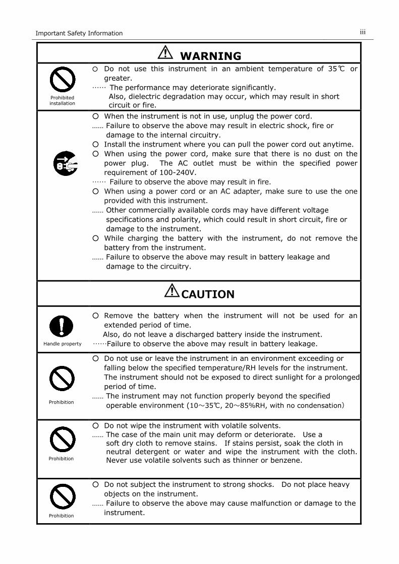
WARNING ○ Do not use this instrument in an ambient temperature of 35℃ or
greater. …… The performance may deteriorate significantly.
Also, dielectric degradation may occur, which may result in short circuit or fire.
○ When the instrument is not in use, unplug the power cord. …… Failure to observe the above may result in electric shock, fire or
damage to the internal circuitry. ○ Install the instrument where you can pull the power cord out anytime. ○ When using the power cord, make sure that there is no dust on the
power plug. The AC outlet must be within the specified power requirement of 100-240V.
…… Failure to observe the above may result in fire. ○ When using a power cord or an AC adapter, make sure to use the one
provided with this instrument. …… Other commercially available cords may have different voltage
specifications and polarity, which could result in short circuit, fire or damage to the instrument.
○ While charging the battery with the instrument, do not remove the battery from the instrument.
…… Failure to observe the above may result in battery leakage and damage to the circuitry.
CAUTION
○ Remove the battery when the instrument will not be used for an extended period of time. Also, do not leave a discharged battery inside the instrument.
……Failure to observe the above may result in battery leakage.
○ Do not use or leave the instrument in an environment exceeding or falling below the specified temperature/RH levels for the instrument. The instrument should not be exposed to direct sunlight for a prolonged period of time.
…… The instrument may not function properly beyond the specified operable environment (10~35℃, 20~85%RH, with no condensation)
○ Do not wipe the instrument with volatile solvents. …… The case of the main unit may deform or deteriorate. Use a
soft dry cloth to remove stains. If stains persist, soak the cloth in neutral detergent or water and wipe the instrument with the cloth. Never use volatile solvents such as thinner or benzene.
○ Do not subject the instrument to strong shocks. Do not place heavy objects on the instrument.
…… Failure to observe the above may cause malfunction or damage to the instrument.
Prohibited installation
Handle property
Prohibition
Prohibition
Prohibition
Important Safety Information iiii
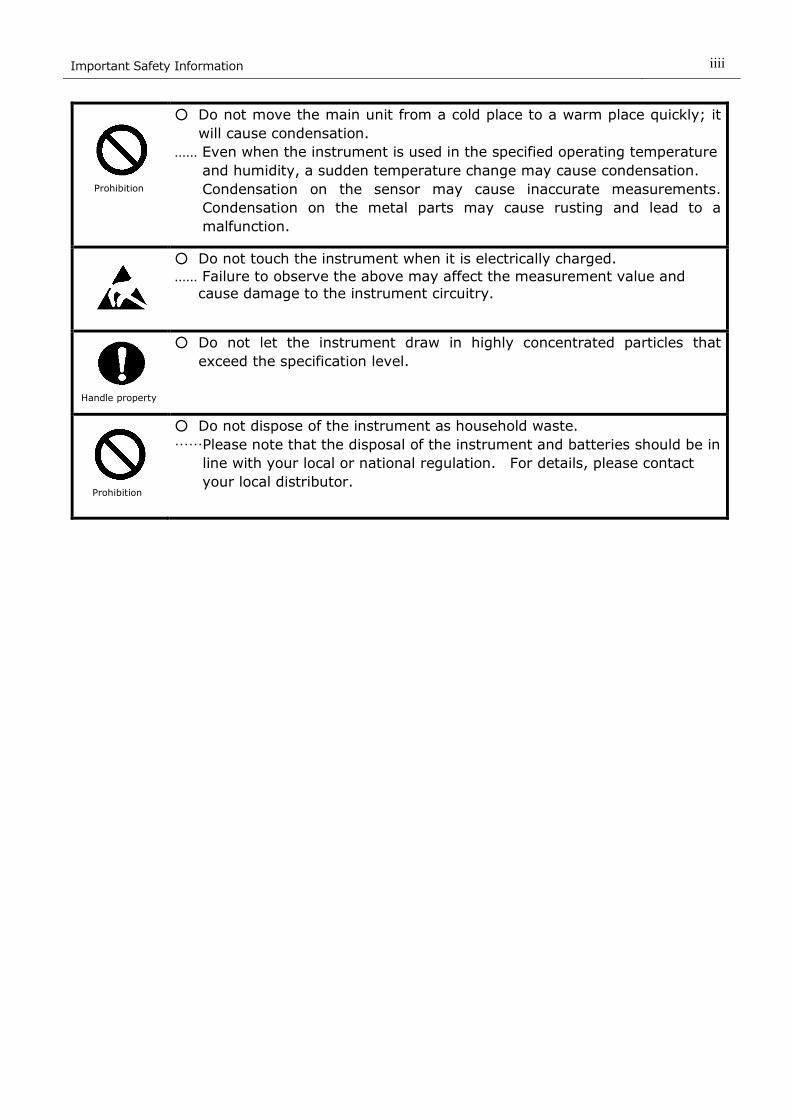
○ Do not move the main unit from a cold place to a warm place quickly; it
will cause condensation. …… Even when the instrument is used in the specified operating temperature
and humidity, a sudden temperature change may cause condensation. Condensation on the sensor may cause inaccurate measurements. Condensation on the metal parts may cause rusting and lead to a malfunction.
○ Do not touch the instrument when it is electrically charged. …… Failure to observe the above may affect the measurement value and
cause damage to the instrument circuitry.
○ Do not let the instrument draw in highly concentrated particles that exceed the specification level.
○ Do not dispose of the instrument as household waste. ……Please note that the disposal of the instrument and batteries should be in line with your local or national regulation. For details, please contact
your local distributor.
Prohibition
Handle property
Prohibition
Table of Contents
1. Part Names and Functions ................................................. 1 1.1 General Outline ................................................................................ 1
1.2 Main Unit ......................................................................................... 2
2. Getting Started .................................................................. 4 2.1 Power Supply ................................................................................... 4
2.2 Refilling the Alcohol Cartridge with Alcohol .......................................... 5
2.2.1 Preparation ............................................................................................. 5
2.2.2 Refilling the Alcohol Cartridge with Alcohol ................................................. 6
2.2.3 Installing the Alcohol Cartridge ................................................................. 7
3. Operation Procedures ........................................................ 8 3.1 Boot and Shutdown ........................................................................... 8
3.2 Main Screen ................................................................................... 10
3.2.1 Main Screen .......................................................................................... 10
3.2.2 The Flow of Screens .............................................................................. 12
3.3 Measurement ................................................................................. 13
3.3.1 SCAN Mode........................................................................................... 13
3.3.2 SINGLE Mode ........................................................................................ 17
3.3.3 In the Event of MEMERR ........................................................................ 20
3.3.4 In the Event the Charger is Not Ready ..................................................... 20
3.4 MENU ............................................................................................ 21
4. Charging the Battery ....................................................... 27 4.1 Charging the Battery ....................................................................... 27
5. Maintenance .................................................................... 28 5.1 Alcohol Cartridge ............................................................................ 28
5.2 Inlet (Cyclone) ............................................................................... 30
5.3 Maintenance Cycle .......................................................................... 31
6. Main Specifications .......................................................... 32 7. Troubleshooting ............................................................... 33 8. Warranty and After Service ............................................. 35
KANOMAX Limited Warranty .................................................................. 35
After Service ........................................................................................ 36
Appendix: Storage Data ....................................................... 37
1. Part Names and Functions 1
1. Part Names and Functions 1.1 General Outline
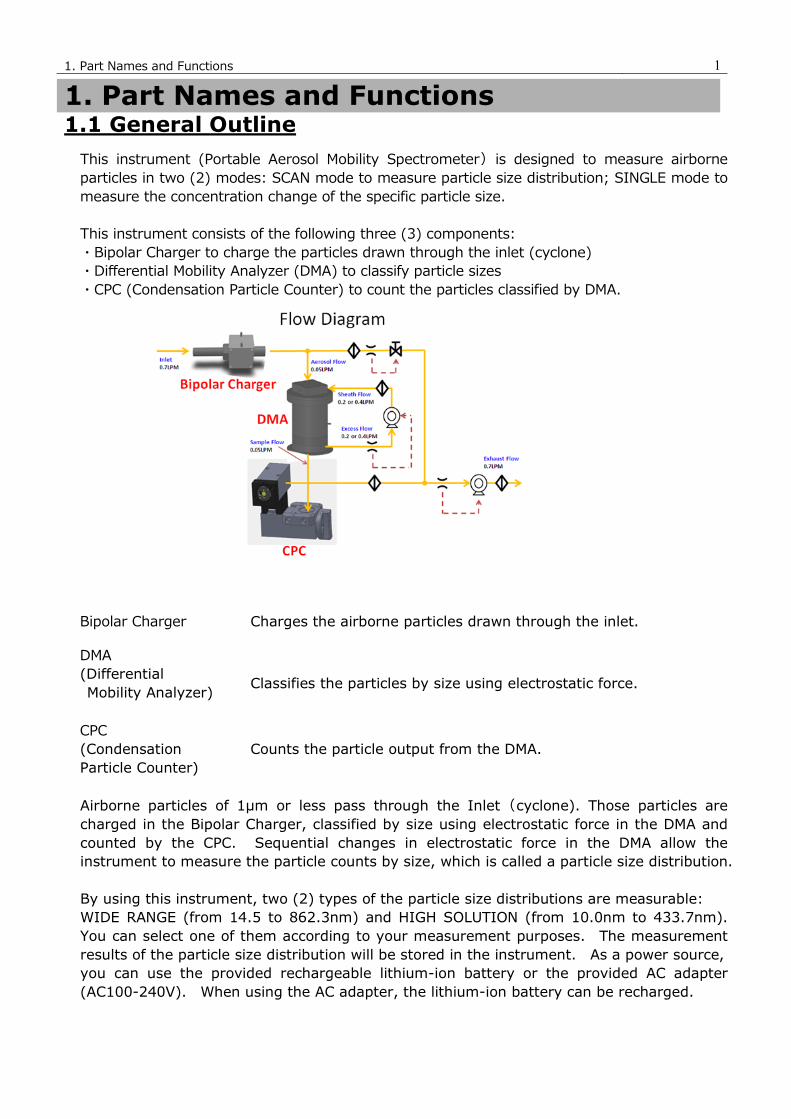
This instrument (Portable Aerosol Mobility Spectrometer)is designed to measure airborne particles in two (2) modes: SCAN mode to measure particle size distribution; SINGLE mode to measure the concentration change of the specific particle size. This instrument consists of the following three (3) components: ・Bipolar Charger to charge the particles drawn through the inlet (cyclone) ・Differential Mobility Analyzer (DMA) to classify particle sizes ・CPC (Condensation Particle Counter) to count the particles classified by DMA.
Bipolar Charger Charges the airborne particles drawn through the inlet.
DMA (Differential Mobility Analyzer)
Classifies the particles by size using electrostatic force.
CPC (Condensation Particle Counter)
Counts the particle output from the DMA.
Airborne particles of 1μm or less pass through the Inlet(cyclone). Those particles are charged in the Bipolar Charger, classified by size using electrostatic force in the DMA and counted by the CPC. Sequential changes in electrostatic force in the DMA allow the instrument to measure the particle counts by size, which is called a particle size distribution. By using this instrument, two (2) types of the particle size distributions are measurable: WIDE RANGE (from 14.5 to 862.3nm) and HIGH SOLUTION (from 10.0nm to 433.7nm). You can select one of them according to your measurement purposes. The measurement results of the particle size distribution will be stored in the instrument. As a power source, you can use the provided rechargeable lithium-ion battery or the provided AC adapter (AC100-240V). When using the AC adapter, the lithium-ion battery can be recharged.

1. Part Names and Functions 2
1.2 Main Unit
POWER switch --- This switch allows you to turn the
instrument off and on.
LCD Touch Panel --- This touch panel allows you to
operate the instrument.
Alcohol Cartridge Inlet --- You can refill the alcohol required for
the internal CPC.
Front
Back
USB Connector (Type A) --- Insert a USB flash drive here to save
data.
Inlet (Cyclone) --- This is a sample air inlet.
Be sure to install the cyclone prior to use.
USB Connector (Mini-B) --- Use this connector to connect with a
PC. The PC recognizes the connection as a COM port.
Top

1. Part Names and Functions 3
Left Side
AC Inlet --- This is an inlet to supply AC power to
the instrument. Connect the provided AC adapter here.
Bottom
Battery Compartment --- Install a rechargeable battery here.
Refer to 2.1 Power Supply for installing the battery.
2. Getting Started 4
2. Getting Started
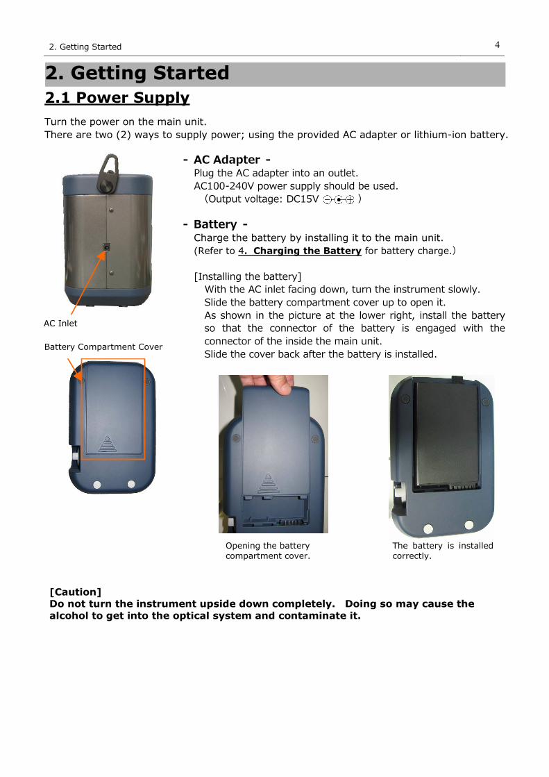
2.1 Power Supply Turn the power on the main unit. There are two (2) ways to supply power; using the provided AC adapter or lithium-ion battery.
- AC Adapter - Plug the AC adapter into an outlet. AC100-240V power supply should be used. (Output voltage: DC15V )
- Battery -
Charge the battery by installing it to the main unit. (Refer to 4.Charging the Battery for battery charge.)
[Installing the battery]
With the AC inlet facing down, turn the instrument slowly. Slide the battery compartment cover up to open it. As shown in the picture at the lower right, install the battery so that the connector of the battery is engaged with the connector of the inside the main unit. Slide the cover back after the battery is installed.
[Caution] Do not turn the instrument upside down completely. Doing so may cause the alcohol to get into the optical system and contaminate it.
Opening the battery compartment cover.
The battery is installed correctly.
AC Inlet
Battery Compartment Cover
2. Getting Started 5
2.2 Refilling the Alcohol Cartridge with Alcohol
Isopropyl Alcohol used for this instrument is a hazardous material. Do not allow the alcohol to contact your eyes and skin. Refer to the Safety Data Sheet (SDS) for handling and storing the alcohol in the alcohol container.
Recap the alcohol container immediately after use to prevent the alcohol from absorbing moisture and from vaporizing.
The CPC in this instrument detects particles using alcohol vapor. Installing the alcohol cartridge soaked in the alcohol solution to this instrument will turn the alcohol into vapor in the CPC. When the alcohol vapor and an airborne particle come in contact with one another, a drop which has the particle at its center will be formed. If the absorbed alcohol solution become less than required, the instrument cannot measure particles correctly. To avoid this, please refill the alcohol cartridge before using the instrument. 2.2.1 Preparation
Isopropyl alcohol (not provided with the instrument) and the following components are required: ・Alcohol bottle ・Storage cap ・Alcohol cartridge
The isopropyl alcohol used for this instrument must be a high-purity guaranteed reagent alcohol. Please refrain from using isopropyl alcohol that is available from stores such as pharmacies or drug stores. The purity of these alcohols is low, and may cause damage to the CPC. Any problems caused by a use of alcohol other than the isopropyl alcohol specified below is not covered by the warranty. Please make sure to use the appropriate alcohol with strict adherence to the handling directions. For the method of refilling alcohol, see 2.2.2 Refilling Alcohol Cartridge with Alcohol. The alcohol used for this instrument must be a guaranteed reagent satisfying at least the following requirements:
When the instrument is not in use, the alcohol cartridge must be stored in the alcohol bottle; the alcohol cartridge insertion opening must be sealed with the storage cap to keep dust out. When the instrument is in use, the storage cap must be used to seal the alcohol bottle.
Chemical name: 2-Propanol Synonym: Isopropyl alcohol Chemical formula: (CH3)2CHOH Formula weight: 60.10 Assay: 99.5% or more
Danger
Caution

2. Getting Started 6
2.2.2 Refilling the Alcohol Cartridge with Alcohol
Do not leave the alcohol cartridge inlet open. Failure to observe the above may cause contamination of the optical system or a malfunction.
1. Turn the instrument off. 2. Open the alcohol bottle by turning the storage cap (or the
alcohol cartridge) about 45° counterclockwise.
Stand the storage cap (or the alcohol cartridge) straight up in a clean place.
3. Pour isopropyl alcohol in the alcohol bottle up to the marked level. Be careful not to tip the bottle and spill the alcohol.
4. Insert the alcohol cartridge into the alcohol bottle, and turn it about 45° clockwise until it is firmly locked.
5. After the alcohol cartridge is set, the felt in the cartridge will be soaked in alcohol. You can use the instrument after a few minutes of soaking the felt in the alcohol.
Alcohol Fill Level
Caution
2. Getting Started 7
2.2.3 Installing the Alcohol Cartridge
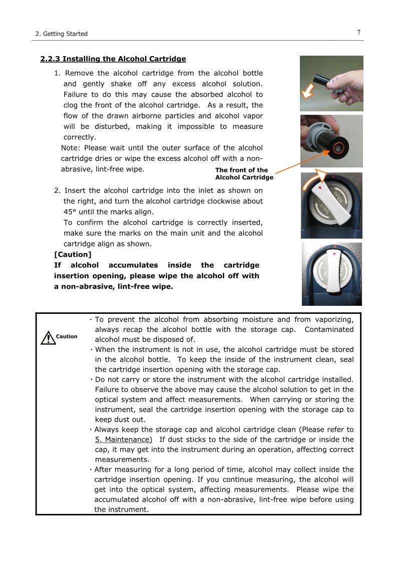
1. Remove the alcohol cartridge from the alcohol bottle and gently shake off any excess alcohol solution. Failure to do this may cause the absorbed alcohol to clog the front of the alcohol cartridge. As a result, the flow of the drawn airborne particles and alcohol vapor will be disturbed, making it impossible to measure correctly.
Note: Please wait until the outer surface of the alcohol cartridge dries or wipe the excess alcohol off with a non-abrasive, lint-free wipe.
2. Insert the alcohol cartridge into the inlet as shown on
the right, and turn the alcohol cartridge clockwise about 45° until the marks align. To confirm the alcohol cartridge is correctly inserted, make sure the marks on the main unit and the alcohol cartridge align as shown.
[Caution] If alcohol accumulates inside the cartridge
insertion opening, please wipe the alcohol off with a non-abrasive, lint-free wipe.
・To prevent the alcohol from absorbing moisture and from vaporizing, always recap the alcohol bottle with the storage cap. Contaminated alcohol must be disposed of.
・When the instrument is not in use, the alcohol cartridge must be stored in the alcohol bottle. To keep the inside of the instrument clean, seal the cartridge insertion opening with the storage cap.
・Do not carry or store the instrument with the alcohol cartridge installed. Failure to observe the above may cause the alcohol solution to get in the optical system and affect measurements. When carrying or storing the instrument, seal the cartridge insertion opening with the storage cap to keep dust out.
・Always keep the storage cap and alcohol cartridge clean (Please refer to 5. Maintenance) If dust sticks to the side of the cartridge or inside the cap, it may get into the instrument during an operation, affecting correct measurements.
・After measuring for a long period of time, alcohol may collect inside the cartridge insertion opening. If you continue measuring, the alcohol will get into the optical system, affecting measurements. Please wipe the accumulated alcohol off with a non-abrasive, lint-free wipe before using the instrument.
The front of the Alcohol Cartridge
Caution
3. Operation Procedures 8
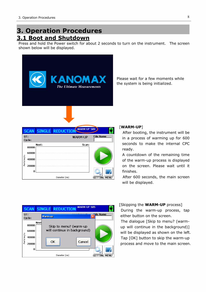
3. Operation Procedures 3.1 Boot and Shutdown Press and hold the Power switch for about 2 seconds to turn on the instrument. The screen shown below will be displayed.
Please wait for a few moments while the system is being initialized.
[WARM-UP] After booting, the instrument will be in a process of warming up for 600 seconds to make the internal CPC ready. A countdown of the remaining time of the warm-up process is displayed on the screen. Please wait until it finishes. After 600 seconds, the main screen will be displayed.
[Skipping the WARM-UP process] During the warm-up process, tap either button on the screen. The dialogue [Skip to menu? (warm-up will continue in the background)] will be displayed as shown on the left. Tap [OK] button to skip the warm-up process and move to the main screen.
3. Operation Procedures 9
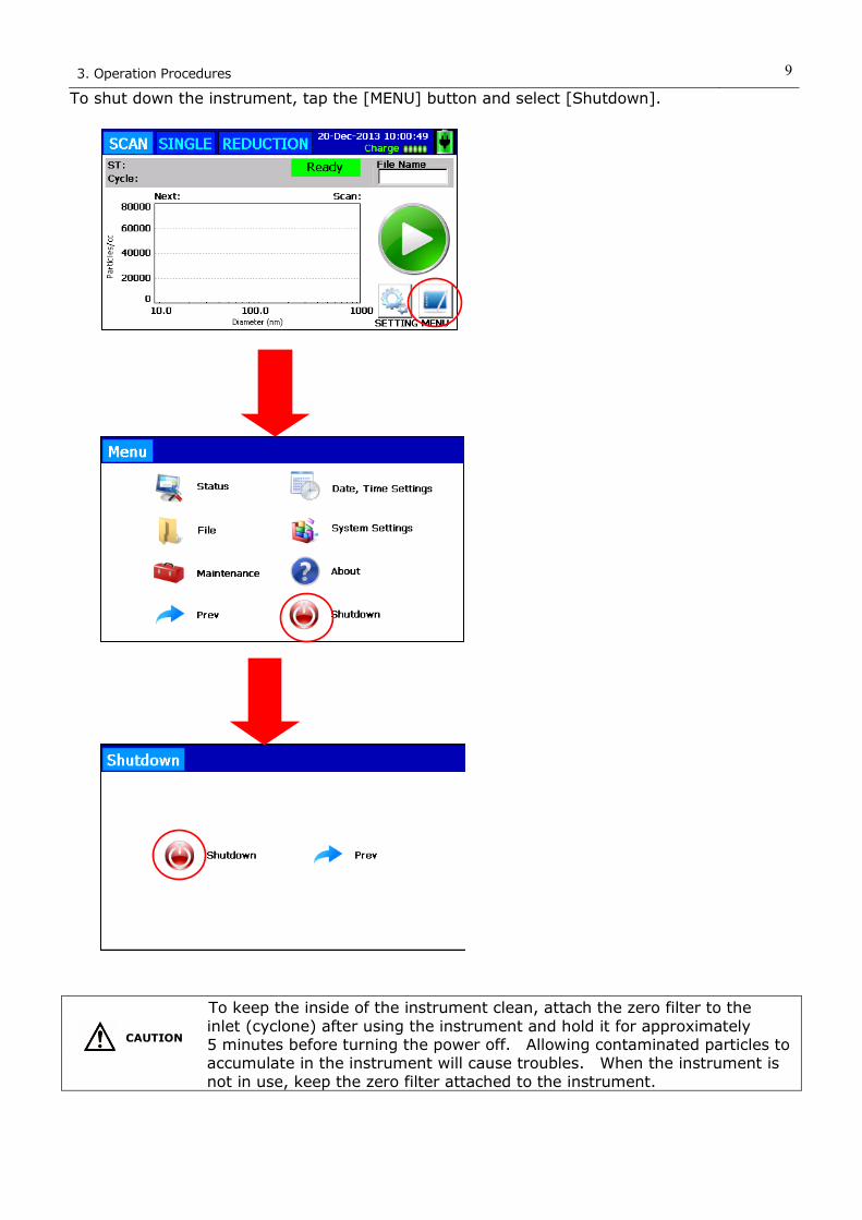
To shut down the instrument, tap the [MENU] button and select [Shutdown].
To keep the inside of the instrument clean, attach the zero filter to the inlet (cyclone) after using the instrument and hold it for approximately 5 minutes before turning the power off. Allowing contaminated particles to accumulate in the instrument will cause troubles. When the instrument is not in use, keep the zero filter attached to the instrument.
CAUTION
3. Operation Procedures 10
3.2 Main Screen 3.2.1 Main Screen
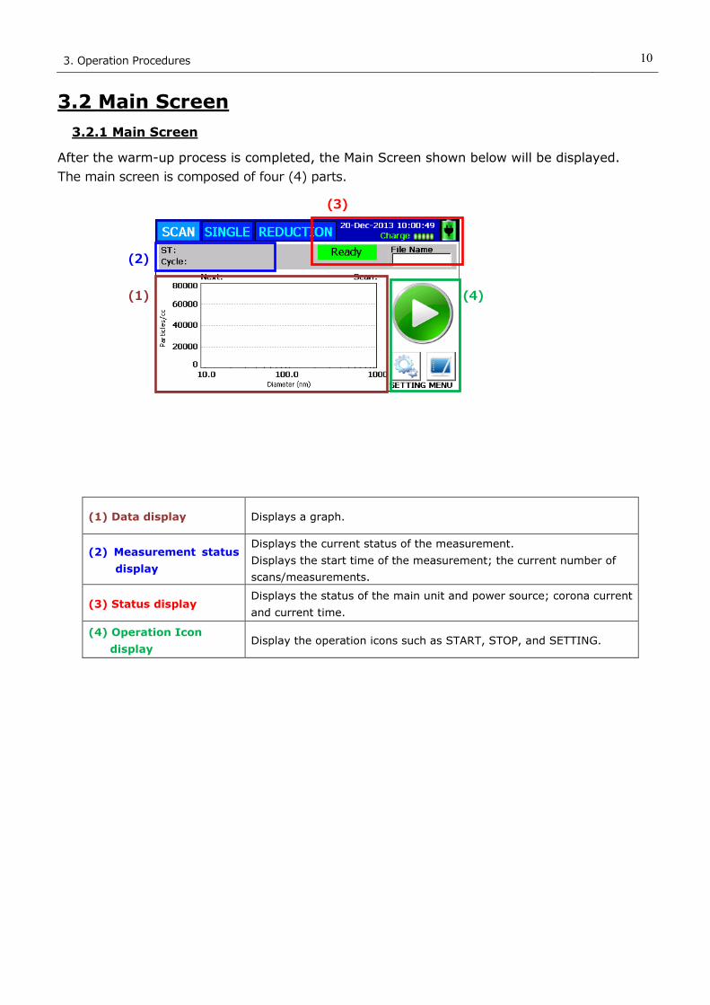
After the warm-up process is completed, the Main Screen shown below will be displayed. The main screen is composed of four (4) parts.
(1) Data display Displays a graph.
(2) Measurement status display
Displays the current status of the measurement. Displays the start time of the measurement; the current number of scans/measurements.
(3) Status display Displays the status of the main unit and power source; corona current and current time.
(4) Operation Icon display
Display the operation icons such as START, STOP, and SETTING.
(1)
(2)
(3)
(4)

3. Operation Procedures 11
After the warm-up process is completed, screens can be switched by tapping the tabs [SCAN], [SINGLE] and [REDUCTION].
[SCAN]: Displays particle size distribution (X axis: particle size, Y axis: number concentration) [SINGLE]:Displays number concentration of the selected particle size
[REDUCTION]:Displays particle size distribution resulting from a compensation calculation.
(X axis: particle size, Y axis: number concentration)
(3) Status Display (in detail)
Displays the conditions of the main unit and power source; corona current and the current time.
Indicates that the instrument is powered by an AC adapter or a battery. When the instrument is battery-operated, the remaining battery level will be also indicated.
Indicates the level of corona current charged to both electrodes on a scale of 1 to 5.
Ready Indicates the instrument is ready to start a measurement.
Measure Indicates a measurement is in process.
Wait Indicates the instrument is preparing for a measurement (e.g. saving data). COMERR Indicates an error on the internal mainboard.
ALCOHOL Indicate that the alcohol is refilled too much.
FLOWERR Indicates the flow rate is not within the specified parameters.
TILTERR Indicates the instrument is tilted.
MEMERR Indicates the internal flash memory has run out of free space.
(4) Operating Icon display
To perform the following operations:
START
Starts a measurement in the mode selected by the tab (SCAN or SINGLE). After a measurement starts, this button will be replaced with the STOP button.
Stops an ongoing measurement. After stopping the measurement, this button will be replaced by the START button.
SETTING
Displays the Measure Settings window for each mode to configure the measurement conditions.
MENU Displays status and stored data; configures the system settings, and etc.
[SCAN]
[SINGLE] [REDUCTION]
STOP
3. Operation Procedures 12
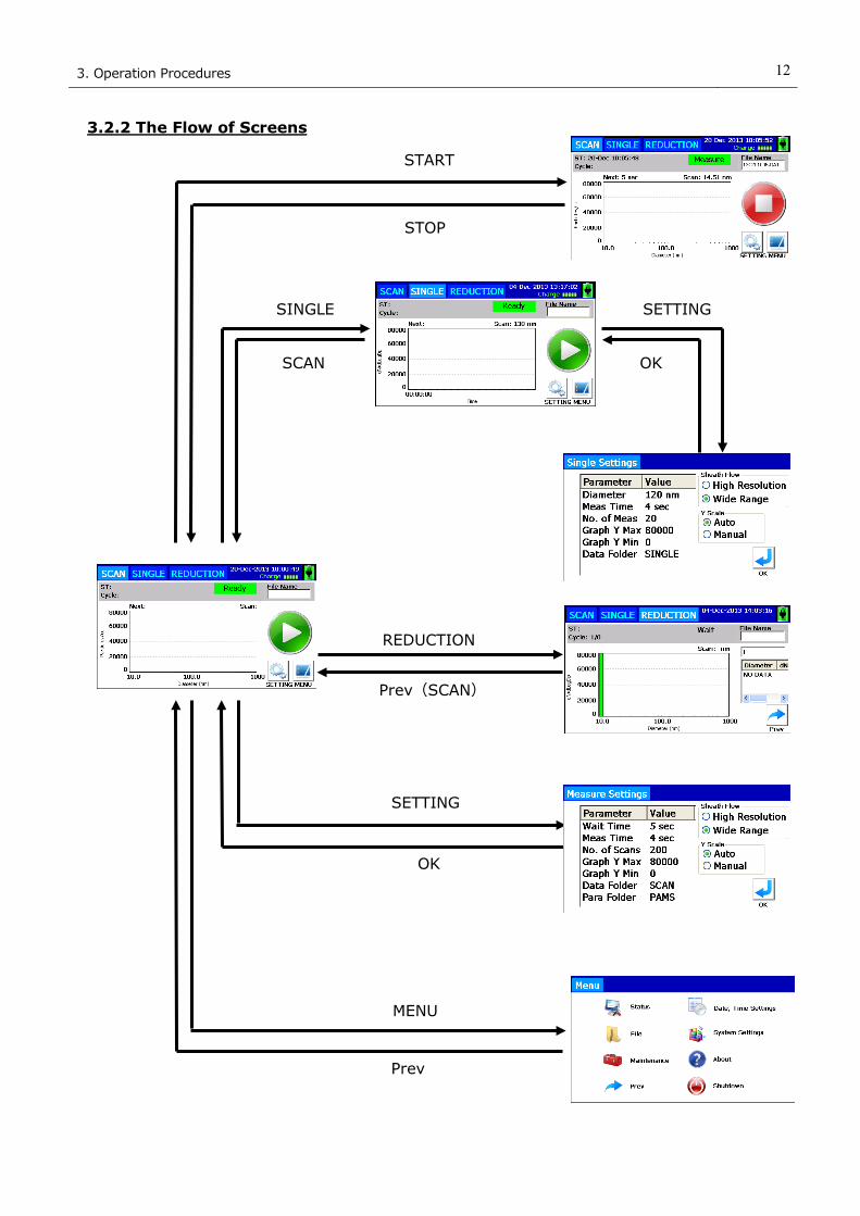
3.2.2 The Flow of Screens
SCAN
REDUCTION
Prev(SCAN)
SINGLE
START
STOP
MENU
Prev
SETTING
OK
SETTING
OK
3. Operation Procedures 13
3.3 Measurement
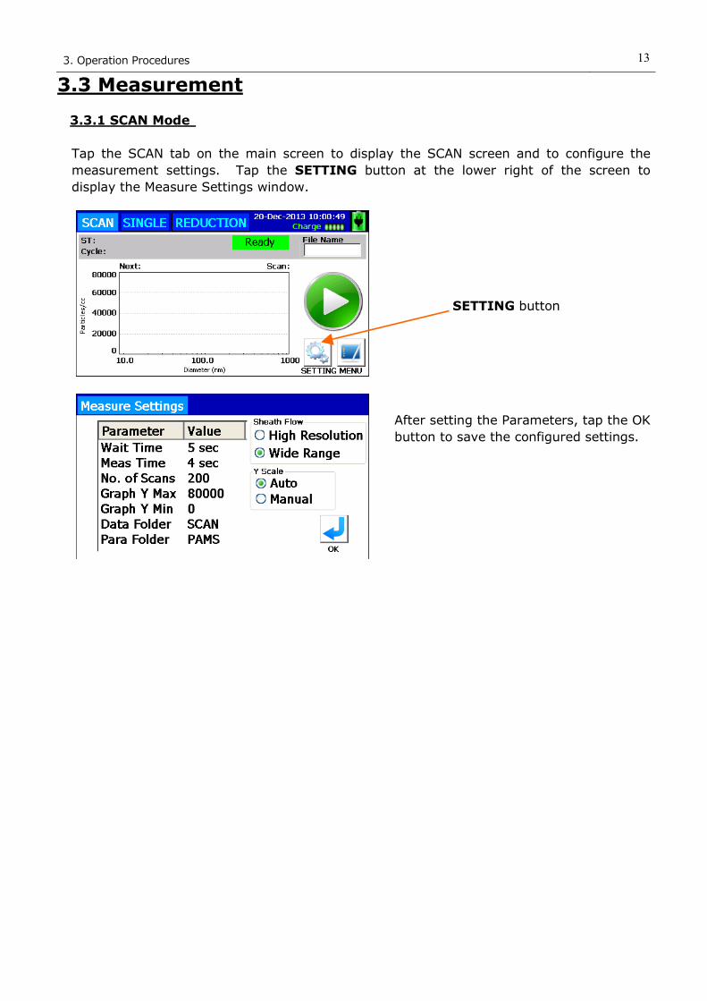
3.3.1 SCAN Mode Tap the SCAN tab on the main screen to display the SCAN screen and to configure the measurement settings. Tap the SETTING button at the lower right of the screen to display the Measure Settings window.
After setting the Parameters, tap the OK button to save the configured settings.
SETTING button

3. Operation Procedures 14
[Measurement Time] If the settings are as follows, the whole measurement time can be calculated as shown below:
(example) Wait Time: 20 seconds Meas Time: 10 seconds/ch No. of Scans: 10 scans Sheath Flow: Wide Range(14ch) Loop Wait: 20 seconds *Loop Wait: wait time set for each scan (unchangeable)
Measurement time = 15 seconds+(20 seconds+10 seconds/chx14ch)x10=1,570 seconds
Wait Time Sets a wait time before starting a measurement. Settable range is from 0 to 600 seconds.
Meas Time Sets a measurement time per channel (ch). Settable range is from 2 to 600 seconds/ch.
No. of Scans Sets the number of scans. Settable range is from 1 to 1,000 scans. Y Scale Select Auto to change the Y axis of the graph automatically
according to the measurement results. Select Manual to fix the Y axis of the graph regardless of the measurement results. Tap Auto or Manual to select either of them.
Graph Y Max Sets the maximum value of the Y axis of the graph. This parameter is valid when the Y Scale is set to Manual. The settable range is from 1 to 30,000,000 pcs/cc.
Graph Y Min Sets the minimum value of the Y axis of the graph. This parameter is valid when the Y Scale is set to Manual. The settable range is from 0 to 29,999,999 pcs/cc.
Data Folder Assign a folder to store the measurement results. When a USB flash drive is installed, this Data Folder will be created on the USB flash drive. The factory default folder is SCAN.
Para Folder Assign a folder to record the parameters. When a USB flash drive is installed, this Para Folder will be created on the USB flash drive. The factory default folder is PAMS.
Sheath Flow In the High Resolution mode, a range from 10nm to 433.7nm is divided into 27 classifications to perform measurements with a high accuracy. In the Wide Range mode, a range from 14.5nm to 862.3nm is divided into 14 classifications to perform quick measurements. Select the High Resolution or Wide Range by tapping either of them.
3. Operation Procedures 15
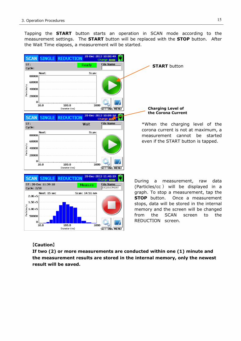
Tapping the START button starts an operation in SCAN mode according to the measurement settings. The START button will be replaced with the STOP button. After the Wait Time elapses, a measurement will be started.
*When the charging level of the corona current is not at maximum, a measurement cannot be started even if the START button is tapped.
During a measurement, raw data (Particles/cc ) will be displayed in a graph. To stop a measurement, tap the STOP button. Once a measurement stops, data will be stored in the internal memory and the screen will be changed from the SCAN screen to the REDUCTION screen.
【Caution】 If two (2) or more measurements are conducted within one (1) minute and the measurement results are stored in the internal memory, only the newest result will be saved.
START button
Charging Level of the Corona Current
3. Operation Procedures 16
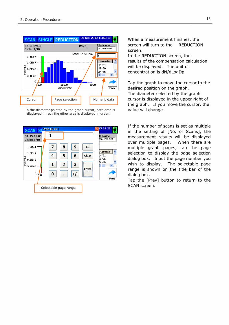
When a measurement finishes, the screen will turn to the REDUCTION screen. In the REDUCTION screen, the results of the compensation calculation will be displayed. The unit of concentration is dN/dLogDp. Tap the graph to move the cursor to the desired position on the graph. The diameter selected by the graph cursor is displayed in the upper right of the graph. If you move the cursor, the value will change. If the number of scans is set as multiple in the setting of [No. of Scans], the measurement results will be displayed over multiple pages. When there are multiple graph pages, tap the page selection to display the page selection dialog box. Input the page number you wish to display. The selectable page range is shown on the title bar of the dialog box. Tap the [Prev] button to return to the SCAN screen.
In the diameter pointed by the graph cursor, data area is displayed in red; the other area is displayed in green.
Selectable page range
Page selection Numeric data Cursor

3. Operation Procedures 17
3.3.2 SINGLE Mode
In SINGLE mode, you can specify a particle size and obtain the chronological change of the concentration. Select the SINGLE tab on the main screen to display the SINGLE mode screen and set the measurement conditions. Tap the SETTING button in the lower right of the screen to display the Measure Settings window.
Tap the SETTING button to display the Single Settings window. After setting the parameters, tap the OK button to save the configured parameters.
SETTING button
3. Operation Procedures 18
[Measurement Time] If the settings are as follows, the whole measurement time can be calculated as follows:
(example) Meas Time: 1 second/ch No. of Meas: 10 times
Measurement Time =1 second x10 times =10 seconds
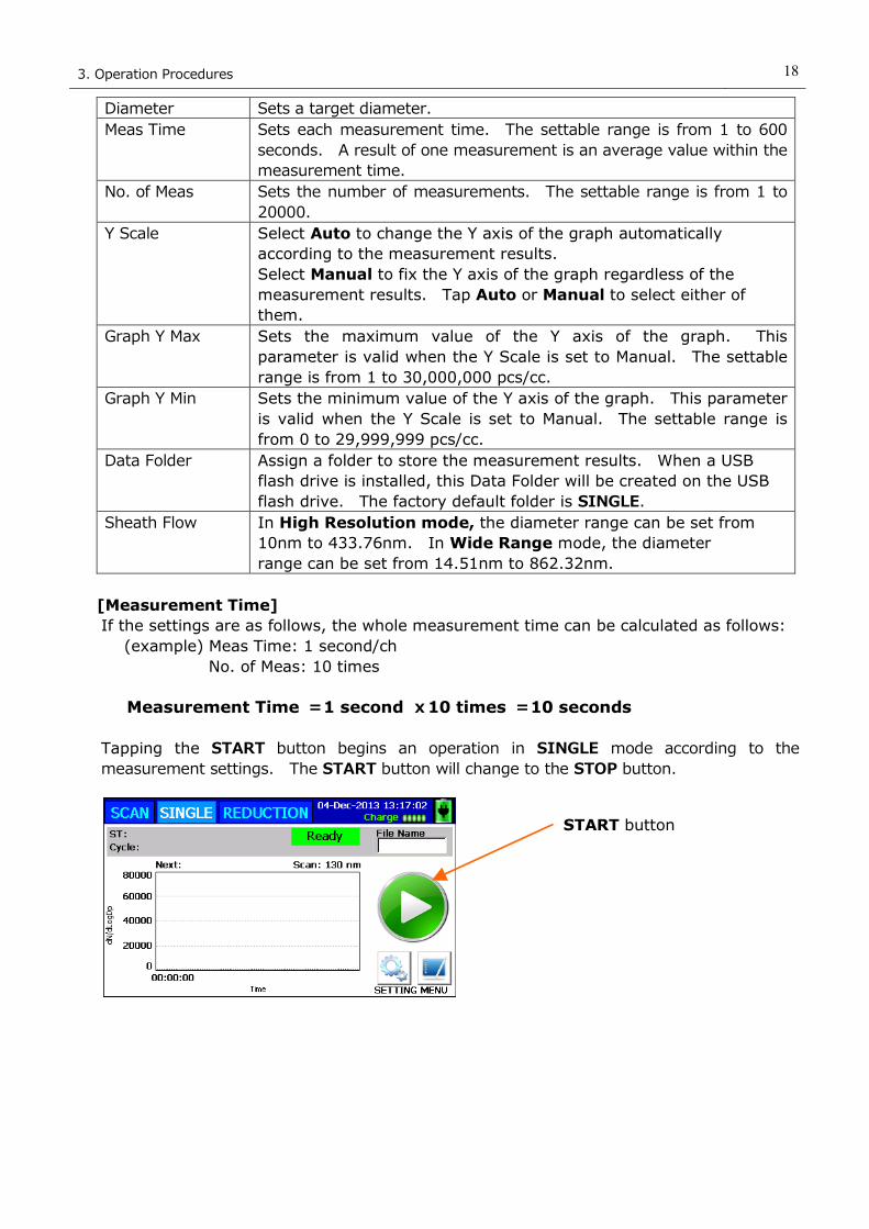
Tapping the START button begins an operation in SINGLE mode according to the measurement settings. The START button will change to the STOP button.
Diameter Sets a target diameter. Meas Time Sets each measurement time. The settable range is from 1 to 600
seconds. A result of one measurement is an average value within the measurement time.
No. of Meas Sets the number of measurements. The settable range is from 1 to 20000.
Y Scale Select Auto to change the Y axis of the graph automatically according to the measurement results. Select Manual to fix the Y axis of the graph regardless of the measurement results. Tap Auto or Manual to select either of them.
Graph Y Max Sets the maximum value of the Y axis of the graph. This parameter is valid when the Y Scale is set to Manual. The settable range is from 1 to 30,000,000 pcs/cc.
Graph Y Min Sets the minimum value of the Y axis of the graph. This parameter is valid when the Y Scale is set to Manual. The settable range is from 0 to 29,999,999 pcs/cc.
Data Folder Assign a folder to store the measurement results. When a USB flash drive is installed, this Data Folder will be created on the USB flash drive. The factory default folder is SINGLE.
Sheath Flow In High Resolution mode, the diameter range can be set from 10nm to 433.76nm. In Wide Range mode, the diameter range can be set from 14.51nm to 862.32nm.
START button
3. Operation Procedures 19
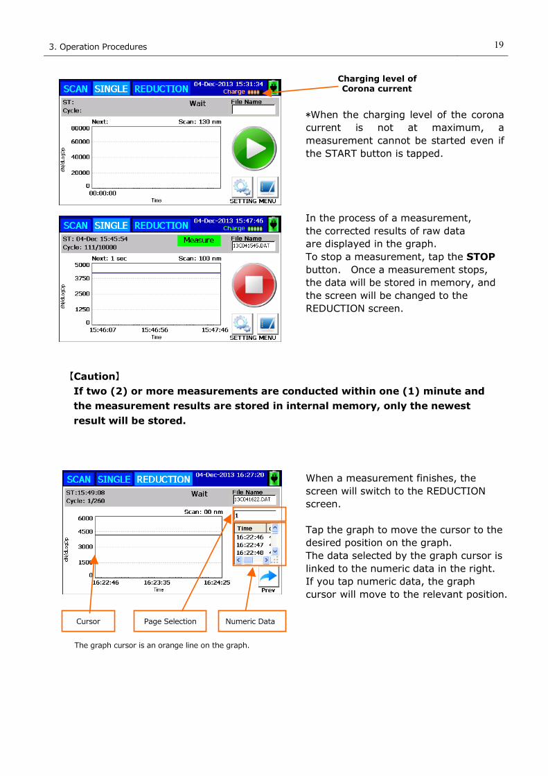
*When the charging level of the corona current is not at maximum, a measurement cannot be started even if the START button is tapped.
In the process of a measurement, the corrected results of raw data are displayed in the graph. To stop a measurement, tap the STOP button. Once a measurement stops, the data will be stored in memory, and the screen will be changed to the REDUCTION screen.
【Caution】
If two (2) or more measurements are conducted within one (1) minute and the measurement results are stored in internal memory, only the newest result will be stored.
When a measurement finishes, the screen will switch to the REDUCTION screen. Tap the graph to move the cursor to the desired position on the graph. The data selected by the graph cursor is linked to the numeric data in the right. If you tap numeric data, the graph cursor will move to the relevant position.
The graph cursor is an orange line on the graph.
Charging level of Corona current
Page Selection Numeric Data Cursor

3. Operation Procedures 20
Up to 100 data from the measurement results can be displayed per page. If you set the number of measurements to more than 100 in the [No. of Meas] settings, the results will be displayed over multiple pages. When there are multiple graph pages, tap the page selection to display the page selection dialog box. Input the page number you wish to display. The selectable page range is shown on the title bar of the dialog. Tap [Prev] button to return to the SCAN-tab screen.
3.3.3 In the Event of MEMERR
When the data storage space runs out, [MEMERR] will be displayed. In the event this error is displayed, select [MENU] [File] and delete some stored data file(s) or move some data file(s) to a USB flash drive.
3.3.4 In the Event the Charger is Not Ready
After turning the power ON, if the charger is not ready within 15 minutes, the message shown to the left will appear on the screen. If this message appears, please refer to 3.4 MENU, Maintenance to do maintenance on the charger.
Selectable page range
3. Operation Procedures 21
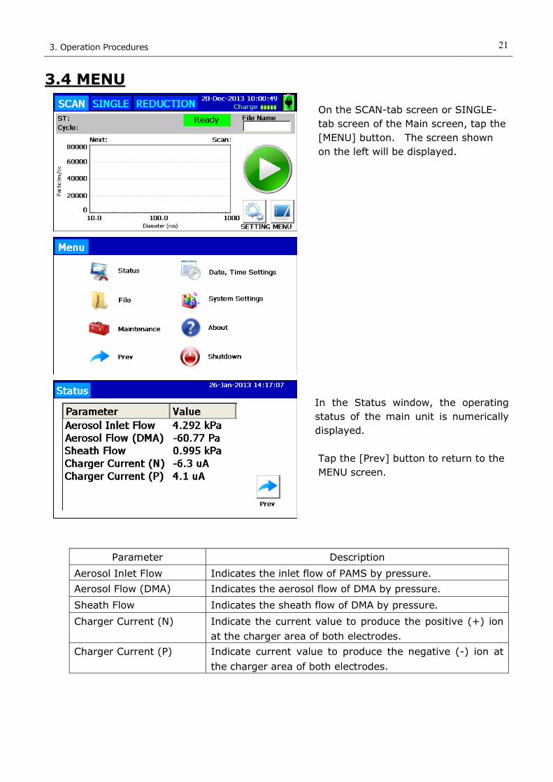
3.4 MENU
On the SCAN-tab screen or SINGLE- tab screen of the Main screen, tap the [MENU] button. The screen shown on the left will be displayed.
· Status
In the Status window, the operating status of the main unit is numerically displayed. Tap the [Prev] button to return to the MENU screen.
Parameter Description Aerosol Inlet Flow Indicates the inlet flow of PAMS by pressure. Aerosol Flow (DMA) Indicates the aerosol flow of DMA by pressure. Sheath Flow Indicates the sheath flow of DMA by pressure. Charger Current (N) Indicate the current value to produce the positive (+) ion
at the charger area of both electrodes. Charger Current (P) Indicate current value to produce the negative (-) ion at
the charger area of both electrodes.

3. Operation Procedures 22
·File
The File window displays the list of measurement data files. You can select a data file to display or delete. If the [Single] checkbox is not ticked, the SCAN mode data files will be displaced. If the checkbox is ticked, the SINGLE mode files will be displayed. Select a file and tap the [Display] button to move to the REDUCTION window and display the data saved in the selected file. Tap the [Prev] button to return to the File window. To delete a file, select the file you wish to delete and tap the [Delete] button to delete it. When a USB flash drive is inserted into the USB connecter, the window shown on the left will be displayed. If you tap the [Copy] button here, all the displayed files will be moved to the USB flash drive. If the [USB] checkbox is ticked, the list of data files stored on the USB flash drive will be displayed. Tap the [Prev] button to return to the Menu screen.
[Caution] Do not insert or remove a USB flash drive during a measurement or you may lose data.

3. Operation Procedures 23
· Maintenance The Maintenance window allows you to refresh the charger. Over time, deposits accumulate on the electrodes in the charger, making the corona current unstable and preventing a measurement from getting started. (Refer to 3.3.4 In the Event the Charger is Not Ready.) After turning the power ON, if the charger is not ready within 15 minutes, the message "Please do maintenance on the charger." will appear on the screen. If this message appears, you can perform maintenance on the charger from the Maintenance menu.
Charger refresh allows the corona current to approach to its normal level: Charger Current(N)= -3.0±1.0uA Charger Current(P)= 3.0±1.0uA Tap the [Start] button to refresh the charger. The [Start] button will be replaced with the [Stop] button. Approximately ten (10) minute later, tap the [Stop] button to finish the process.
3. Operation Procedures 24
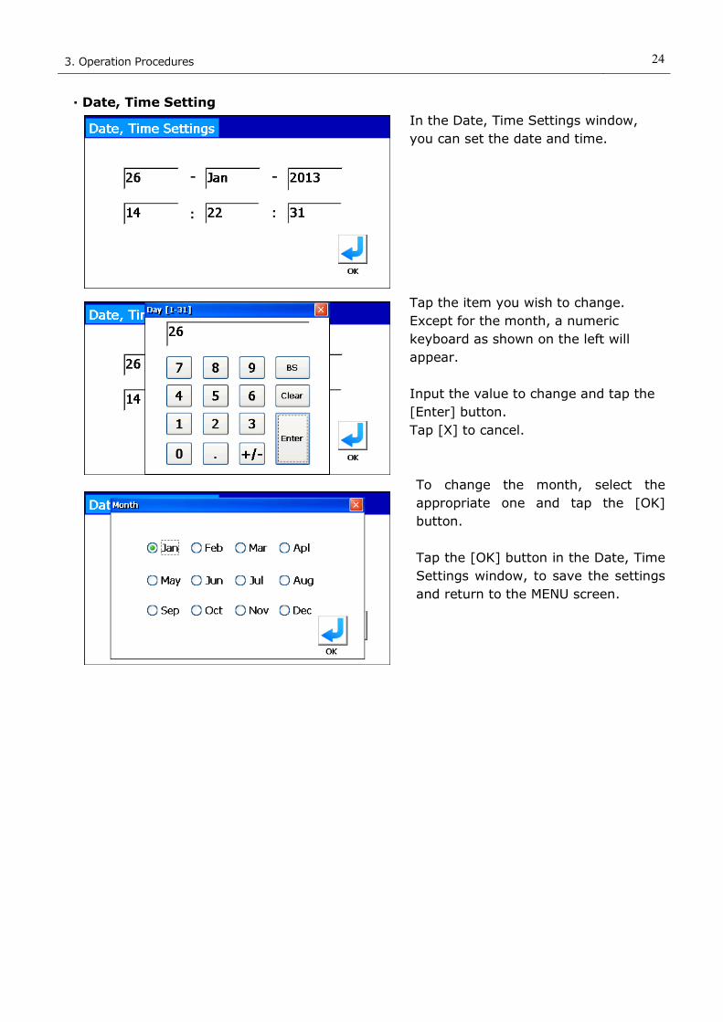
· Date, Time Setting
In the Date, Time Settings window, you can set the date and time.
Tap the item you wish to change. Except for the month, a numeric keyboard as shown on the left will appear. Input the value to change and tap the [Enter] button. Tap [X] to cancel.
To change the month, select the appropriate one and tap the [OK] button. Tap the [OK] button in the Date, Time Settings window, to save the settings and return to the MENU screen.
3. Operation Procedures 25
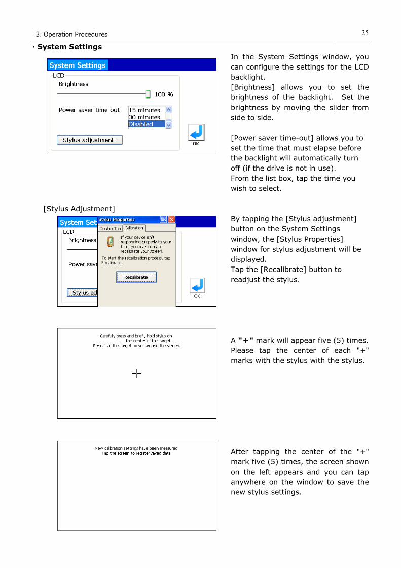
· System Settings In the System Settings window, you can configure the settings for the LCD backlight. [Brightness] allows you to set the brightness of the backlight. Set the brightness by moving the slider from side to side. [Power saver time-out] allows you to set the time that must elapse before the backlight will automatically turn off (if the drive is not in use). From the list box, tap the time you wish to select.
[Stylus Adjustment] By tapping the [Stylus adjustment] button on the System Settings window, the [Stylus Properties] window for stylus adjustment will be displayed. Tap the [Recalibrate] button to readjust the stylus.
A "+" mark will appear five (5) times. Please tap the center of each "+" marks with the stylus with the stylus.
After tapping the center of the "+" mark five (5) times, the screen shown on the left appears and you can tap anywhere on the window to save the new stylus settings.
3. Operation Procedures 26
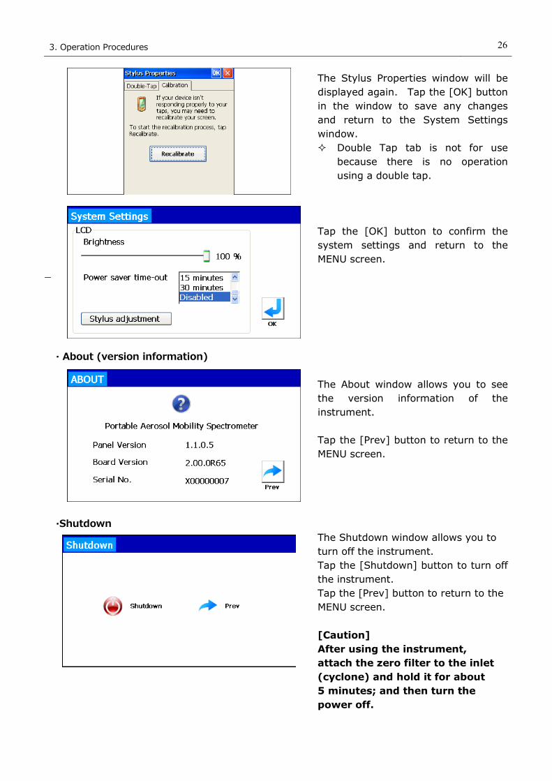
The Stylus Properties window will be displayed again. Tap the [OK] button in the window to save any changes and return to the System Settings window. Double Tap tab is not for use
because there is no operation using a double tap.
Tap the [OK] button to confirm the system settings and return to the MENU screen.
_
· About (version information) The About window allows you to see the version information of the instrument. Tap the [Prev] button to return to the MENU screen.
·Shutdown
The Shutdown window allows you to turn off the instrument. Tap the [Shutdown] button to turn off the instrument. Tap the [Prev] button to return to the MENU screen. [Caution] After using the instrument, attach the zero filter to the inlet (cyclone) and hold it for about 5 minutes; and then turn the power off.
4. Charging the Battery 27
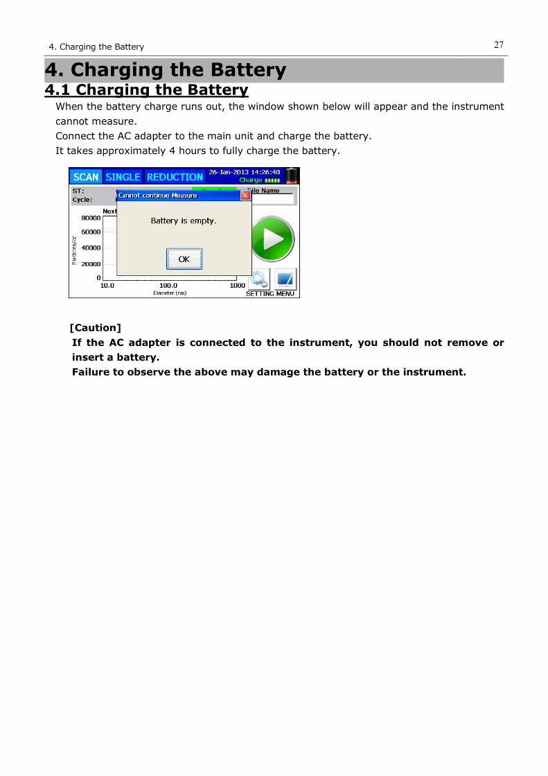
4. Charging the Battery 4.1 Charging the Battery
When the battery charge runs out, the window shown below will appear and the instrument cannot measure. Connect the AC adapter to the main unit and charge the battery. It takes approximately 4 hours to fully charge the battery.
[Caution] If the AC adapter is connected to the instrument, you should not remove or insert a battery. Failure to observe the above may damage the battery or the instrument.
5. Maintenance 28
5. Maintenance The instrument requires routine maintenance according to the instruction below. In addition an annual calibration is required; please return the instrument to the KANOMAX service center or your distributor. This annual maintenance will ensure the instrument stays in good condition and performs accurate measurements.
5.1 Alcohol Cartridge
The alcohol cartridge is equipped with an isopropyl alcohol reservoir. The felt inside the cartridge absorbs and retains the alcohol. The alcohol cartridge is inserted in the main unit; therefore it must be kept clean. If dust gets into the instrument, it may clog the internal nozzle and affect the proper operation of the instrument. Be careful when storing and handling the alcohol cartridge and storage cap to keep them free of contamination. Cleaning and Replacing the Felt The felt and mesh inside the alcohol cartridge can be replaced on site. The instrument is provided with one (1) set of spare felt and mesh. In normal use, there is no need to replace the felt unless the problems shown below occur: 1.The felt is contaminated with dust or oil.
→ This problem does not happen when the instrument is used in normal ambient air. If the instrument is used for sampling highly-concentrated particles (sampling in a boiler room or sampling combustion aerosols), the felt may become contaminated and require replacement.
2.The mesh inside the alcohol cartridge is clogged. → If the alcohol cartridge has been soaked in contaminated alcohol for a long time,
the mesh inside the alcohol cartridge may be clogged. The mesh can be cleaned by washing it, but if the clogging persists, it must be replaced.
3.The instrument is not able to measure due to humidity. → If humid air is drawn in the instrument, moisture may accumulate in the alcohol
cartridge. In this case, the felt must be removed and allowed to dry before being returned to the cartridge. If the felt or mesh is obviously contaminated, it must be replaced with the provided spare. Over time the felt may become discolored, however, this will not cause a performance problem.
DO NOT OPEN the outer case of the instrument. It is very dangerous to open the outer case of the instrument because a Class 3B laser diode is contained in the instrument. Opening the instrument case will void the warranty. For annual maintenance, or for any service not described in this operation manual, please contact the KANOMAX service center or your distributor.
Danger

5. Maintenance 29
・Checking and Replacing the Felt and Mesh ①To remove the felt from the alcohol cartridge, hold the cartridge with both hands near
the joint line and push the cap off the cylinder. The cartridge will be separated into two (2) parts and the white felt will be visible (See Figure ① below).
② After the cartridge is separated, use the felt removal tool (a small wooden stick) to
push the felt and mesh out of the cartridge cylinder (See Figure ② below). ③ Make sure that the felt and mesh are clean.
If no contamination is found on the felt, it can be reused. After the felt is dry, please reassemble. If the felt is obviously contaminated, it must be replaced with the spare and disposed of. Hold the mesh in front of a light source and look to make sure that all the holes of the mesh are clean and open. If the mesh holes are clogged, blow air on the mesh to clear the clogs. If the clogging persists, replace the mesh with the provided spare mesh.
Assembling the Cartridge
Before assembly, make sure that each part is clean. If there is dust or debris stuck to the felt, it may get into the instrument and cause several problems. Please confirm that there is no dust in the alcohol cartridge or on the felt.
Insert a clean mesh into the cartridge cylinder and confirm that it lies flat on the bottom of the cylinder. Then insert the felt until it reaches the bottom of the cylinder and assemble the alcohol cartridge by reversing the steps shown above. Finally, blow air on the surface of the alcohol cartridge.
① Disassemble the alcohol cartridge.
② Remove the felt and mesh from the cartridge cylinder.
Caution
5. Maintenance 30
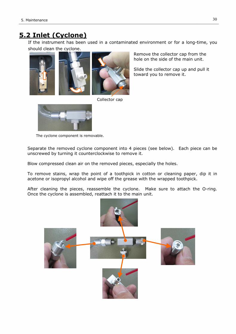
5.2 Inlet (Cyclone) If the instrument has been used in a contaminated environment or for a long-time, you should clean the cyclone.
Remove the collector cap from the hole on the side of the main unit. Slide the collector cap up and pull it toward you to remove it.
Separate the removed cyclone component into 4 pieces (see below). Each piece can be unscrewed by turning it counterclockwise to remove it. Blow compressed clean air on the removed pieces, especially the holes. To remove stains, wrap the point of a toothpick in cotton or cleaning paper, dip it in acetone or isopropyl alcohol and wipe off the grease with the wrapped toothpick. After cleaning the pieces, reassemble the cyclone. Make sure to attach the O-ring. Once the cyclone is assembled, reattach it to the main unit.
Collector cap
The cyclone component is removable.

5. Maintenance 31
5.3 Maintenance Cycle
To operate this instrument correctly, please follow the recommended maintenance shown below. We highly recommend you refill the alcohol cartridge with alcohol every time before using the instrument. Conduct other maintenance, as necessary depending on the frequency of use and/or condition of the instrument.
Items Maintenance Frequency Alcohol Cartridge Soak the cartridge in the
alcohol. Daily (or every time before using) (Refer to 2.2 Refilling the Alcohol Cartridge with Alcohol)
Felt inside the Alcohol Cartridge
Replace the felt inside the alcohol cartridge.
When necessary (Refer to 5.1 Alcohol Cartridge and 7.Troubleshooting.)
Alcohol Cartridge Insertion Opening
Wipe off any alcohol accumulated inside the cartridge opening.
Before using the instrument (Refer to 2.2 Refilling the Alcohol Cartridge with Alcohol)
Zero Filter Attach the zero filter to the inlet (cyclone).
After using the instrument Attach the zero filter and allow about 5 minutes before turning the power off. (Refer to 3.1 Boot and Shutdown)
Inlet (Cyclone) Clean the inlet (cyclone). When necessary (Refer to 5.2 Inlet (Cyclone) and 7. Troubleshooting)
Charger On the Menu screen, tap the Maintenance button to refresh the charger.
When the message "Please do maintenance on the charger." appears on the screen. When the charging level of the corona current does not reach its maximum. (Refer to 3.4 MENU)
Main Unit Return the instrument to your distributor for cleaning and calibration.
Once a year
6. Main Specifications 32
6. Main Specifications
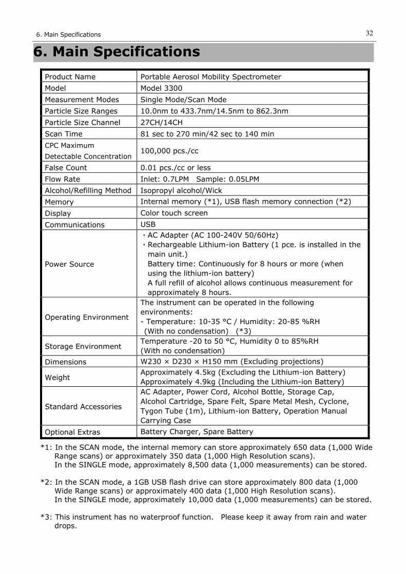
Product Name Portable Aerosol Mobility Spectrometer Model Model 3300 Measurement Modes Single Mode/Scan Mode Particle Size Ranges 10.0nm to 433.7nm/14.5nm to 862.3nm Particle Size Channel 27CH/14CH Scan Time 81 sec to 270 min/42 sec to 140 min CPC Maximum Detectable Concentration
100,000 pcs./cc
False Count 0.01 pcs./cc or less Flow Rate Inlet: 0.7LPM Sample: 0.05LPM Alcohol/Refilling Method Isopropyl alcohol/Wick Memory Internal memory (*1), USB flash memory connection (*2) Display Color touch screen Communications USB
Power Source
・AC Adapter (AC 100-240V 50/60Hz) ・Rechargeable Lithium-ion Battery (1 pce. is installed in the main unit.) Battery time: Continuously for 8 hours or more (when using the lithium-ion battery) A full refill of alcohol allows continuous measurement for approximately 8 hours.
Operating Environment
The instrument can be operated in the following environments: - Temperature: 10-35 °C / Humidity: 20-85 %RH (With no condensation) (*3)
Storage Environment Temperature -20 to 50 °C, Humidity 0 to 85%RH (With no condensation)
Dimensions W230 × D230 × H150 mm (Excluding projections)
Weight Approximately 4.5kg (Excluding the Lithium-ion Battery) Approximately 4.9kg (Including the Lithium-ion Battery)
Standard Accessories
AC Adapter, Power Cord, Alcohol Bottle, Storage Cap, Alcohol Cartridge, Spare Felt, Spare Metal Mesh, Cyclone, Tygon Tube (1m), Lithium-ion Battery, Operation Manual Carrying Case
Optional Extras Battery Charger, Spare Battery
*1: In the SCAN mode, the internal memory can store approximately 650 data (1,000 Wide Range scans) or approximately 350 data (1,000 High Resolution scans). In the SINGLE mode, approximately 8,500 data (1,000 measurements) can be stored.
*2: In the SCAN mode, a 1GB USB flash drive can store approximately 800 data (1,000 Wide Range scans) or approximately 400 data (1,000 High Resolution scans). In the SINGLE mode, approximately 10,000 data (1,000 measurements) can be stored.
*3: This instrument has no waterproof function. Please keep it away from rain and water drops.

7. Troubleshooting 33
7. Troubleshooting
Symptom Possible Cause Troubleshooting
A count value is too low (lower than expected).
Alcohol shortage Refill the alcohol cartridge with alcohol (Refer to 2.2 Refilling the Alcohol Cartridge with Alcohol.)
The particle count in the measured area is actually low.
Moisture has accumulated inside the alcohol cartridge.
Replace the felt inside the alcohol cartridge or dry the felt. (Refer to 5.1 Alcohol Cartridge)
The inlet (cyclone) is clogged.
Check the inlet (cyclone) for clogs. Clean it if necessary. (Refer to 5.2 Inlet (Cyclone))
Pump has problems due to low flow (or no flow)
Please check the pump performance. Check the screen for an error message. Check the flow rate of the pump with a flow meter. The flow rate must be approximately 700cc/min.
The instrument is being operated in an environment outside the specified operable range.
Operate the instrument in the specified environment.
The alcohol is poor quality or is contaminated.
Replace the felt inside the alcohol cartridge. Use only the appropriate alcohol as specified. (Refer to 5.1 Alcohol Cartridge)
The mesh is clogged.
The mesh may be clogged with excess alcohol. Remove the excess alcohol. (Refer to 5.1 Alcohol Cartridge)
Dust and/or alcohol got into the optical system.
Contact your distributor or the KANOMAX service center (see the last page of this manual).
The instrument requires a calibration and/or service.
Contact your distributor or the KANOMAX service center (see the last page of this manual).
7. Troubleshooting 34
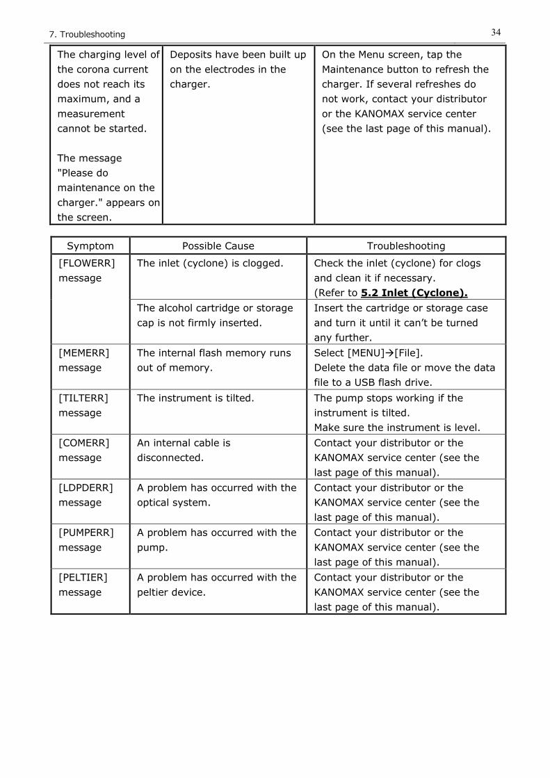
The charging level of the corona current does not reach its maximum, and a measurement cannot be started. The message "Please do maintenance on the charger." appears on the screen.
Deposits have been built up on the electrodes in the charger.
On the Menu screen, tap the Maintenance button to refresh the charger. If several refreshes do not work, contact your distributor or the KANOMAX service center (see the last page of this manual).
Symptom Possible Cause Troubleshooting
[FLOWERR] message
The inlet (cyclone) is clogged.
Check the inlet (cyclone) for clogs and clean it if necessary. (Refer to 5.2 Inlet (Cyclone).
The alcohol cartridge or storage cap is not firmly inserted.
Insert the cartridge or storage case and turn it until it can’t be turned any further.
[MEMERR] message
The internal flash memory runs out of memory.
Select [MENU][File]. Delete the data file or move the data file to a USB flash drive.
[TILTERR] message
The instrument is tilted. The pump stops working if the instrument is tilted. Make sure the instrument is level.
[COMERR] message
An internal cable is disconnected.
Contact your distributor or the KANOMAX service center (see the last page of this manual).
[LDPDERR] message
A problem has occurred with the optical system.
Contact your distributor or the KANOMAX service center (see the last page of this manual).
[PUMPERR] message
A problem has occurred with the pump.
Contact your distributor or the KANOMAX service center (see the last page of this manual).
[PELTIER] message
A problem has occurred with the peltier device.
Contact your distributor or the KANOMAX service center (see the last page of this manual).
8.Warranty and After Service 35
8. Warranty and After Service KANOMAX Limited Warranty
The limited warranty set below is given by KANOMAX JAPAN Inc. (hereafter referred to as “KJI") with respect to this instrument, its attachment parts and other accessories (hereafter referred to as “PRODUCT”) that you have purchased. PRODUCT you have purchased shall be the only one that the limited warranty stated herein applies to. Your PRODUCT, when delivered to you in new condition in its original container, is warranted against defects in materials or workmanship as follows: for a period of one (1) year from the date of original purchase, defective parts or a defective PRODUCT returned to KJI, as applicable, and proven to be defective upon inspection, will be exchanged for a new or comparable rebuilt parts, or a refurbished PRODUCT as determined by KJI. Warranty for such replacements shall not extend the original warranty period of the defective PRODUCT. To obtain service under this warranty, you must notify Kanomax JAPAN, Inc. on or before the expiration of the warranty period to obtain directions for returning the defective product. You are responsible for all return shipping charges to the authorized Kanomax service center. This limited warranty covers all defects encountered in normal use of the PRODUCT, and does not apply to the following cases: (1) Use of parts or supplies other than the PRODUCT sold by KJI, which cause damage to
the PRODUCT or cause abnormally frequent service calls or service problems. (2) If any PRODUCT has its serial number or date altered or removed. (3) Loss or damage to the PRODUCT due to abuse, mishandling, improper packaging by
the owner, alteration, accident, electrical current fluctuations, failure to follow operating, maintenance or environmental instructions prescribed in the PRODUCT's instruction manual provided by KJI, or service performed by other than KJI.
NO IMPLIED WARRANTY, INCLUDING ANY IMPLIED WARRANTY OF MERCHANTABILITY OR FITNESS FOR A PARTICULAR PURPOSE, APPLIES TO THE PRODUCT AFTER THE APPLICABLE PERIOD OF THE EXPRESS LIMITED WARRANTY STATED ABOVE, AND NO OTHER EXPRESS WARRANTY OR GUARANTY, EXCEPT AS MENTIONED ABOVE, GIVEN BY ANY PERSON OR ENTITY WITH RESPECT TO THE PRODUCT SHALL BIND KJI. KJI SHALL NOT BE LIABLE FOR LOSS OF STORAGE CHARGES, LOSS OR CORRUPTION OF DATA, OR ANY OTHER SPECIAL, INCIDENTAL OR CONSEQUENTIAL DAMAGES CAUSED BY THE USE OR MISUSE OF, OR INABILITY TO USE, THE PRODUCT, REGARDLESS OF THE LEGAL THEORY ON WHICH THE CLAIM IS BASED, AND EVEN IF KJI HAS BEEN ADVISED OF THE POSSIBILITY OF SUCH DAMAGES. IN NO EVENT SHALL RECOVERY OF ANY KIND AGAINST KJI BE GREATER IN AMOUNT THAN THE PURCHASE PRICE OF THE PRODUCT SOLD BY KJI AND CAUSING THE ALLEGED DAMAGE. WITHOUT LIMITING THE FOREGOING, THE OWNER ASSUMES ALL RISK AND LIABILITY FOR LOSS, DAMAGE OF, OR INJURY TO THE OWNER AND THE OWNER'S PROPERTY AND TO OTHERS AND THEIR PROPERTY ARISING OUT OF USE OR MISUSE OF, OR INABILITY TO USE, THE PRODUCT NOT CAUSED DIRECTLY BY THE NEGLIGENCE OF KJI. THIS LIMITED WARRANTY SHALL NOT EXTEND TO ANYONE OTHER THAN THE ORIGINAL PURCHASER OF THE PRODUCT, OR THE PERSON FOR WHOM IT WAS PURCHASED AS A GIFT, AND STATES THE PURCHASER'S EXCLUSIVE REMEDY.

8.Warranty and After Service 36
After Service
・When you have a problem with your instrument, please check out the “ Troubleshooting”
first.
・If that does not solve the problem, please contact your local distributor or call our service
center (See the last page for contact information.)
・During the warranty period, we will repair at no charge a product that proves to be
defective due to material or workmanship under normal use (See the above "KANOMAX
Limited Warranty). All return shipping charges are the responsibility of the customer.
・Repair after warranty expiration:
Upon request, we will repair the instrument at the customer’s expense, if the instrument’s performance is found to be recoverable by providing the repair.
・Replacement parts are available for a minimum period of five (5) years after termination of production. This storage period of replacement parts is considered as the period during which we can provide repair service. For further information, please contact your local distributor, or contacts on the last page. When you call, please have the following information at hand: 1) PRODUCT name 2) Model number 3) Serial number 4) Description of symptom in detail 5) Date of purchase
Appendix 37
Appendix: Storage Data
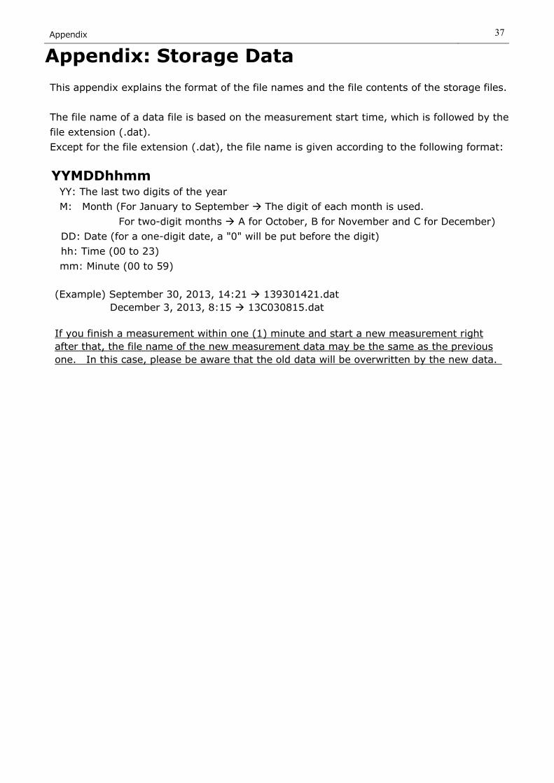
This appendix explains the format of the file names and the file contents of the storage files. The file name of a data file is based on the measurement start time, which is followed by the file extension (.dat). Except for the file extension (.dat), the file name is given according to the following format: YYMDDhhmm
YY: The last two digits of the year M: Month (For January to September The digit of each month is used.
For two-digit months A for October, B for November and C for December) DD: Date (for a one-digit date, a "0" will be put before the digit) hh: Time (00 to 23)
mm: Minute (00 to 59) (Example) September 30, 2013, 14:21 139301421.dat
December 3, 2013, 8:15 13C030815.dat
If you finish a measurement within one (1) minute and start a new measurement right after that, the file name of the new measurement data may be the same as the previous one. In this case, please be aware that the old data will be overwritten by the new data.
Appendix 38
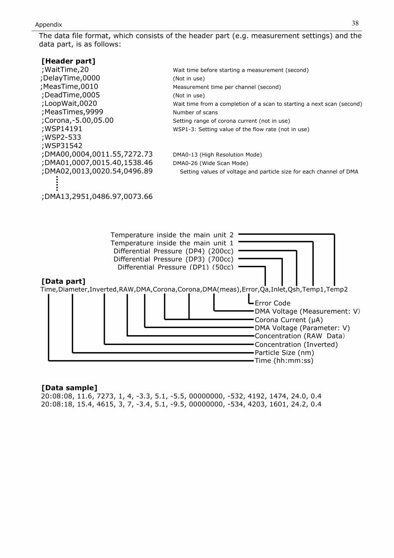
The data file format, which consists of the header part (e.g. measurement settings) and the data part, is as follows: [Header part] ;WaitTime,20 Wait time before starting a measurement (second) ;DelayTime,0000 (Not in use) ;MeasTime,0010 Measurement time per channel (second) ;DeadTime,0005 (Not in use) ;LoopWait,0020 Wait time from a completion of a scan to starting a next scan (second) ;MeasTimes,9999 Number of scans ;Corona,-5.00,05.00 Setting range of corona current (not in use) ;WSP14191 WSP1-3: Setting value of the flow rate (not in use) ;WSP2-533 ;WSP31542 ;DMA00,0004,0011.55,7272.73 DMA0-13 (High Resolution Mode) ;DMA01,0007,0015.40,1538.46 DMA0-26 (Wide Scan Mode) ;DMA02,0013,0020.54,0496.89 Setting values of voltage and particle size for each channel of DMA ;DMA13,2951,0486.97,0073.66
[Data part] Time,Diameter,Inverted,RAW,DMA,Corona,Corona,DMA(meas),Error,Qa,Inlet,Qsh,Temp1,Temp2
[Data sample] 20:08:08, 11.6, 7273, 1, 4, -3.3, 5.1, -5.5, 00000000, -532, 4192, 1474, 24.0, 0.4 20:08:18, 15.4, 4615, 3, 7, -3.4, 5.1, -9.5, 00000000, -534, 4203, 1601, 24.2, 0.4
Temperature inside the main unit 2 Temperature inside the main unit 1 Differential Pressure (DP4) (200cc) Differential Pressure (DP3) (700cc) Differential Pressure (DP1) (50cc)
Error Code DMA Voltage (Measurement: V) Corona Current (µA) DMA Voltage (Parameter: V) Concentration (RAW Data) Concentration (Inverted) Particle Size (nm) Time (hh:mm:ss)
39
USA KANOMAX USA, INC. 219 US HWY 206, Andover, NJ 07821 USA TEL: +1(800) 247-8887(USA), +1(973) 786-6386 FAX: +1(973) 786-7586 URL: http://www.kanomax-usa.com/ E-Mail: [email protected]
JAPAN KANOMAX JAPAN, INC. 2-1 Shimizu Suita City, Osaka 565-0805, Japan TEL: 81-6-6877-0183 FAX: 81-6-6877-5570 URL: http://www.kanomax.co.jp/ E-Mail: [email protected]
Copyright © Kanomax Japan Inc. All rights reserved. 2013-2014 No copying, distribution, publication, modification, or incorporation of this document, in whole or part, is permitted for commercial purposes without the express written permission of Kanomax. The contents of this document may be changed without prior notice.
02002/14.06