Embed Size (px)
Citation preview

Portable Anchor System
Table of Contents 1. Introduction
Product Overview 1 Component Overview 3 Testing and Warnings 4 NFPA Users Information 6
2. Assembly Instructions Leg Connections 8 Height Adjustment-Leg assembly configurations 8 Head Angle Adjustments 9 Leg Clamps 11 Ball Feet & Modular Foot System 12 Leg Hobble 16 Main Attachment Point/Pins 17 Auxiliary Attachment Points 19 Head Assembly-Tripod, Quadpod, A-Frame 19 Lash Ring 20 Strengths of Auxiliary Attachment Points 21 Final Assembly – How to put it all together 22
3. TerrAdaptor Accessories QuickLash 23 Standard Winch Bracket 24 Capstan Winch Bracket 24 Capstan Winch System 25
4. Configurations Symmetric Tripod 28 Symmetric Quadpod 31 Edge-A Tripod 32 A Frame/Bi-pod 33 Gin Pole/ Monopod 34 Horizontal Span 35 Field Use Charts 36 Inspection & Maintenance Log 37
5. Warranty and Replacement Parts 38


TerrAdaptor Users Manual (Jan 2013) 1
Section 1
Introduction
Product Overview Congratulations on your purchase of the TerrAdaptor Portable Anchor System. The TerrAdaptor is the most versatile portable anchor system available for use in rescue, industrial, and wilderness environments. This innovate high directional system is the result of the combined years of experience in the design, use and manufacturing of equipment by Pigeon Mountain Industries (PMI), Skedco, and Seattle Manufacturing Corporation (SMC). The TerrAdaptor system is unique in that it configures as a gin pole/monopod, an A-Frame/Bipod, a Quadpod and, of course, the most adjustable Tripod in the market today. Due to the extreme adjustability of the TerrAdaptor, countless non-standard configurations are available utilizing shallow angles and horizontals that are not available with other tripod systems in the market. With independently variable head angles and interchangeable components, the TerrAdaptor will adjust to your rescue environment whether it is rural, urban, industrial, or confined space.
Layout of this Manual This manual is designed to aid in the assembly and configuration of the TerrAdaptor Portable Anchor System. It is not designed to provide the user with the theory and practice of using portable anchor systems, as this comes only from extensive training from qualified trainers on such systems. Do not attempt to use the TerrAdaptor without this specialized training as you could be killed or seriously injured. Section 2, Assembly Instruction, includes a detailed description of each of the major components of the TerrAdaptor System. This section explains how the individual pieces are used as well as how they are assembled together. Within each component description there is a “best practice” element, care and maintenance, as well as specific warnings for that element. Please refer to this section during routine inspection of the TerrAdaptor system as well as during your initial assembly process. Section 3, TerrAdaptor Accessories, includes information on care, maintenance, use and warnings for accessories which are now available for the TerrAdaptor. These accessories add flexibility and functionality that may not be present in your base TerrAdaptor model. Please make sure the product information sheets you receive when purchasing accessories are added to this section so that all users of your TerrAdaptor will have access to the most up-to-date information. In addition, as you continue to use your TerrAdaptor and find it being used in more unique applications and wish you had the perfect accessory for the situation, please don’t hesitate to contact us with your ideas.
TerrAdaptor Users Manual (Jan 2013) 2
Section 4, Configurations, includes information regarding various standard configurations the TerrAdaptor system has been designed for. This section summarizes the various settings needed to achieve the configuration as well as the breaking strength achieved for the configuration. The NFPA and ASTM standard achieved at each configuration is also indicated, if applicable. Section 5, Warranty and Replacement Parts, describes the warranty policy on your TerrAdaptor System and component parts. In addition, this section provides the listing of the component parts and their part numbers included in each kit available for purchase. Please refer to this section upon receiving your kit to assure all of your parts are properly included in the kits, as well as for a list of replacement parts that are available from your dealer.
The TerrAdaptor System Multiple configurations of the TerrAdaptor Portable Anchor System can be built from various standard system components. The primary system revolves around the TerrAdaptor Tripod System (Part number NFPA230100). This system includes all of the necessary parts to assemble a standard symmetric tripod that provides the ability to reach a height of approximately10-feet. The system comes packaged in three compact packable bags to make it easy to “grab your bags and go” as well as store the System together in an organized manner. The individual component pieces included in the TerrAdaptor Tripod System are listed in Section 5 of this manual. To transition your Tripod to a Quadpod System, you can purchase the TerrAdaptor Quadpod Attachment Kit (Part Number 230105). This kit provides the fourth leg and attachment pieces necessary to transition your tripod into a quadpod. The individual component pieces included in the TerrAdaptor Quadpod are listed in Section 5 of this manual. If your needs are fairly simple and a single gin pole is the best solution for your situation, you can purchase the TerrAdaptor Gin Pole Kit (Part number 230106). This kit includes a full leg kit to reach approximately 10 feet in height adjustability. The individual component pieces for this kit are listed in Section 5. For those who typically encounter environments that require more than 10 feet of height, additional leg extension pieces (appropriately 4 feet in length) can be individually purchased for this use. This piece can also be used to provide one extra long leg if a tall “lazy leg” configuration is desired. Other replacement parts and options are available for the TerrAdaptor system and are listed in Section 5 of this manual.
TerrAdaptor Users Manual (Jan 2013) 3
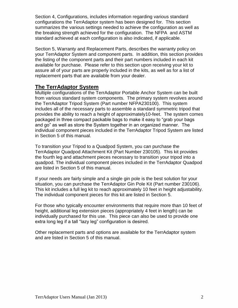
Major component Overview
The images below are an overview of a tripod set-up.
Fig 6 2
Fig 6 1
Figure 7 1
An overview of the head section along with the correct names of each component is presented below. Please refer to this image while learning how to assemble the TerrAdaptor as outline in Section 2.
TerrAdaptor Users Manual (Jan 2013) 4
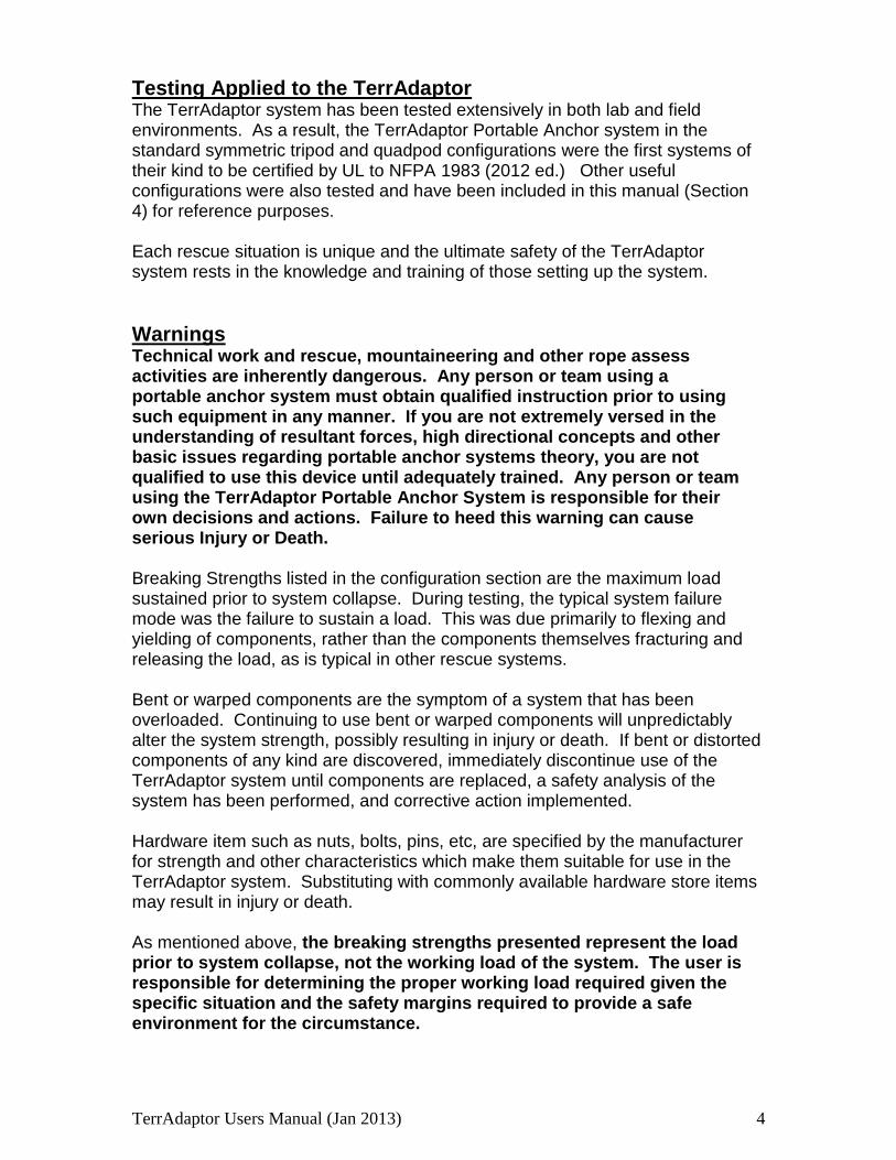
Testing Applied to the TerrAdaptor The TerrAdaptor system has been tested extensively in both lab and field environments. As a result, the TerrAdaptor Portable Anchor system in the standard symmetric tripod and quadpod configurations were the first systems of their kind to be certified by UL to NFPA 1983 (2012 ed.) Other useful configurations were also tested and have been included in this manual (Section 4) for reference purposes. Each rescue situation is unique and the ultimate safety of the TerrAdaptor system rests in the knowledge and training of those setting up the system.
Warnings
Technical work and rescue, mountaineering and other rope assess activities are inherently dangerous. Any person or team using a portable anchor system must obtain qualified instruction prior to using such equipment in any manner. If you are not extremely versed in the understanding of resultant forces, high directional concepts and other basic issues regarding portable anchor systems theory, you are not qualified to use this device until adequately trained. Any person or team using the TerrAdaptor Portable Anchor System is responsible for their own decisions and actions. Failure to heed this warning can cause serious Injury or Death. Breaking Strengths listed in the configuration section are the maximum load sustained prior to system collapse. During testing, the typical system failure mode was the failure to sustain a load. This was due primarily to flexing and yielding of components, rather than the components themselves fracturing and releasing the load, as is typical in other rescue systems. Bent or warped components are the symptom of a system that has been overloaded. Continuing to use bent or warped components will unpredictably alter the system strength, possibly resulting in injury or death. If bent or distorted components of any kind are discovered, immediately discontinue use of the TerrAdaptor system until components are replaced, a safety analysis of the system has been performed, and corrective action implemented. Hardware item such as nuts, bolts, pins, etc, are specified by the manufacturer for strength and other characteristics which make them suitable for use in the TerrAdaptor system. Substituting with commonly available hardware store items may result in injury or death. As mentioned above, the breaking strengths presented represent the load prior to system collapse, not the working load of the system. The user is responsible for determining the proper working load required given the specific situation and the safety margins required to provide a safe environment for the circumstance.
TerrAdaptor Users Manual (Jan 2013) 5
Please see our website www.TerrAdaptor.com for a listing of trainers that have extensive training experience with portable anchor systems. These trainers have experience with the TerrAdaptor.
YOU COULD BE KILLED OR SERIOUSLY INJURED IF YOU DO NOT
READ AND UNDERSTAND THE USER INFORMATION BEFORE USING THIS PIECE OF EQUIPMENT
SPECIAL TRAINING AND KNOWLEDGE ARE REQUIRED TO USE THIS EQUIPMENT
YOU MUST THOROUGHLY READ AND UNDERSTAND ALL MANUFACTURER’S INSTRUCTIONS BEFORE USE
TerrAdaptor Users Manual (Jan 2013) 6
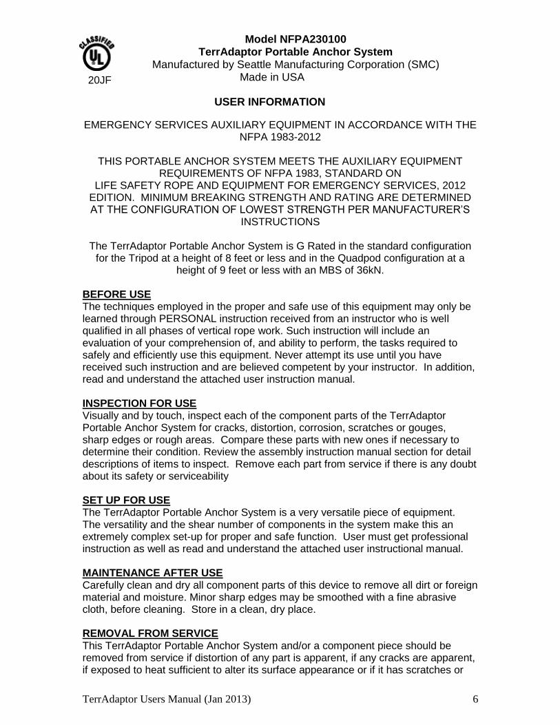
Model NFPA230100 TerrAdaptor Portable Anchor System
Manufactured by Seattle Manufacturing Corporation (SMC) Made in USA
USER INFORMATION
EMERGENCY SERVICES AUXILIARY EQUIPMENT IN ACCORDANCE WITH THE NFPA 1983-2012
THIS PORTABLE ANCHOR SYSTEM MEETS THE AUXILIARY EQUIPMENT
REQUIREMENTS OF NFPA 1983, STANDARD ON LIFE SAFETY ROPE AND EQUIPMENT FOR EMERGENCY SERVICES, 2012
EDITION. MINIMUM BREAKING STRENGTH AND RATING ARE DETERMINED AT THE CONFIGURATION OF LOWEST STRENGTH PER MANUFACTURER’S
INSTRUCTIONS
The TerrAdaptor Portable Anchor System is G Rated in the standard configuration for the Tripod at a height of 8 feet or less and in the Quadpod configuration at a
height of 9 feet or less with an MBS of 36kN.
BEFORE USE The techniques employed in the proper and safe use of this equipment may only be learned through PERSONAL instruction received from an instructor who is well qualified in all phases of vertical rope work. Such instruction will include an evaluation of your comprehension of, and ability to perform, the tasks required to safely and efficiently use this equipment. Never attempt its use until you have received such instruction and are believed competent by your instructor. In addition, read and understand the attached user instruction manual. INSPECTION FOR USE Visually and by touch, inspect each of the component parts of the TerrAdaptor Portable Anchor System for cracks, distortion, corrosion, scratches or gouges, sharp edges or rough areas. Compare these parts with new ones if necessary to determine their condition. Review the assembly instruction manual section for detail descriptions of items to inspect. Remove each part from service if there is any doubt about its safety or serviceability SET UP FOR USE The TerrAdaptor Portable Anchor System is a very versatile piece of equipment. The versatility and the shear number of components in the system make this an extremely complex set-up for proper and safe function. User must get professional instruction as well as read and understand the attached user instructional manual. MAINTENANCE AFTER USE Carefully clean and dry all component parts of this device to remove all dirt or foreign material and moisture. Minor sharp edges may be smoothed with a fine abrasive cloth, before cleaning. Store in a clean, dry place. REMOVAL FROM SERVICE This TerrAdaptor Portable Anchor System and/or a component piece should be removed from service if distortion of any part is apparent, if any cracks are apparent, if exposed to heat sufficient to alter its surface appearance or if it has scratches or
20JF
TerrAdaptor Users Manual (Jan 2013) 7
gouges of more than a superficial nature. Review the assembly instruction manual for detail descriptions of potential problems with component parts. ADDITIONAL INFORMATION Additional information regarding this type of equipment can be found in the following publications: NFPA 1500, Standard on Fire Department Occupational Safety and Health Program NFPA 1983, Standard on Life Safety Rope and Equipment for Emergency Services RECORDS It is suggested that the user of this portable anchor system keep a permanent record listing the date and results of each usage inspection. Such record should show, as a minimum, inspection for all of the following conditions for each component of the system. Refer to the user manual for explanation detail for each component piece:
Cleanliness
Dryness
Corrosion
Distortion
Excessive wear
Scratches
Gouges
Sharp edges
Presence of User Information sheet and User Instruction Manual. USE OF THIS USER INFORMATION SHEET It is suggested that this User Information sheet be retained in a permanent record after it is separated from the TerrAdaptor Portable Anchor System and that a copy of it be kept with the device. It is suggested that the user refer to this User Instructions before and after each use of this device.
YOU COULD BE KILLED OR SERIOUSLY INJURED IF YOU DO NOT
READ AND UNDERSTAND THE USER INFORMATION BEFORE USING THIS PIECE OF EQUIPMENT
SPECIAL TRAINING AND KNOWLEDGE ARE REQUIRED TO USE THIS EQUIPMENT
YOU MUST THOROUGHLY READ AND UNDERSTAND ALL MANUFACTURER’S INSTRUCTIONS BEFORE USE
USE AND INSPECT THIS EQUIPMENT ONLY IN ACCORDANCE WITH THESE INSTRUCTIONS
Manufactured by
SEATTLE MANUFACTURING CORPORATION 6930 SALASHAN PARKWAY- FERNDALE, WA. 98248 (800) 426-6251
WWW.SMCGEAR.NET This sheet has been prepared in accordance with the requirements of NFPA

TerrAdaptor Users Manual (Jan 2013) 8
Section 2
Assembly instructions The TerrAdaptor is the most versatile and configurable portable anchor system on the market. This section will provide detailed information about each component in the system and how these components are assembled with one another. See Section 4 for instructions on setting up various configurations.
Leg Tube Connections
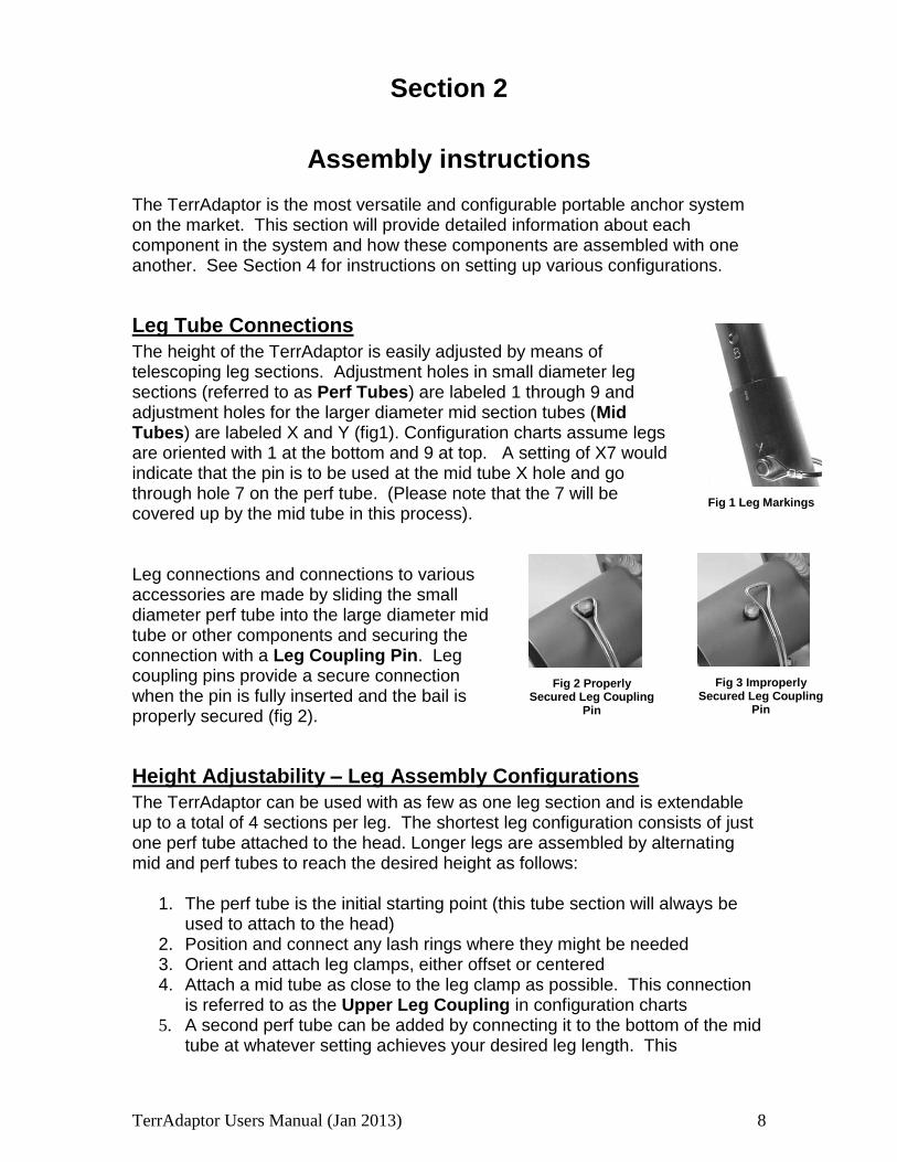
The height of the TerrAdaptor is easily adjusted by means of telescoping leg sections. Adjustment holes in small diameter leg sections (referred to as Perf Tubes) are labeled 1 through 9 and adjustment holes for the larger diameter mid section tubes (Mid Tubes) are labeled X and Y (fig1). Configuration charts assume legs are oriented with 1 at the bottom and 9 at top. A setting of X7 would indicate that the pin is to be used at the mid tube X hole and go through hole 7 on the perf tube. (Please note that the 7 will be covered up by the mid tube in this process).
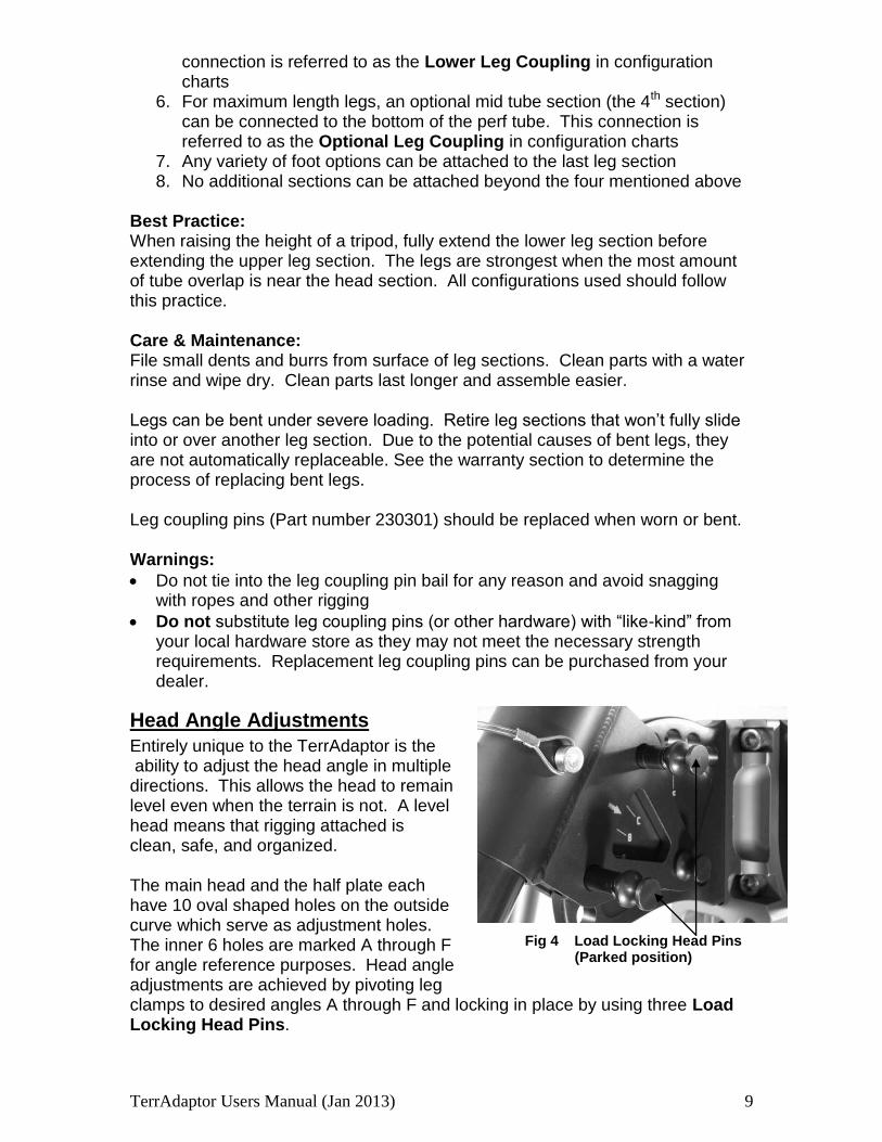
Leg connections and connections to various accessories are made by sliding the small diameter perf tube into the large diameter mid tube or other components and securing the connection with a Leg Coupling Pin. Leg coupling pins provide a secure connection when the pin is fully inserted and the bail is properly secured (fig 2).
Height Adjustability – Leg Assembly Configurations
The TerrAdaptor can be used with as few as one leg section and is extendable up to a total of 4 sections per leg. The shortest leg configuration consists of just one perf tube attached to the head. Longer legs are assembled by alternating mid and perf tubes to reach the desired height as follows:
1. The perf tube is the initial starting point (this tube section will always be used to attach to the head)
2. Position and connect any lash rings where they might be needed 3. Orient and attach leg clamps, either offset or centered 4. Attach a mid tube as close to the leg clamp as possible. This connection
is referred to as the Upper Leg Coupling in configuration charts 5. A second perf tube can be added by connecting it to the bottom of the mid
tube at whatever setting achieves your desired leg length. This
Fig 1 Leg Markings
Fig 2 Properly
Secured Leg Coupling Pin
Fig 3 Improperly
Secured Leg Coupling Pin
TerrAdaptor Users Manual (Jan 2013) 9
connection is referred to as the Lower Leg Coupling in configuration charts
6. For maximum length legs, an optional mid tube section (the 4th section) can be connected to the bottom of the perf tube. This connection is referred to as the Optional Leg Coupling in configuration charts
7. Any variety of foot options can be attached to the last leg section 8. No additional sections can be attached beyond the four mentioned above
Best Practice: When raising the height of a tripod, fully extend the lower leg section before extending the upper leg section. The legs are strongest when the most amount of tube overlap is near the head section. All configurations used should follow this practice. Care & Maintenance: File small dents and burrs from surface of leg sections. Clean parts with a water rinse and wipe dry. Clean parts last longer and assemble easier. Legs can be bent under severe loading. Retire leg sections that won’t fully slide into or over another leg section. Due to the potential causes of bent legs, they are not automatically replaceable. See the warranty section to determine the process of replacing bent legs. Leg coupling pins (Part number 230301) should be replaced when worn or bent. Warnings:
Do not tie into the leg coupling pin bail for any reason and avoid snagging with ropes and other rigging
Do not substitute leg coupling pins (or other hardware) with “like-kind” from your local hardware store as they may not meet the necessary strength requirements. Replacement leg coupling pins can be purchased from your dealer.
Head Angle Adjustments
Entirely unique to the TerrAdaptor is the
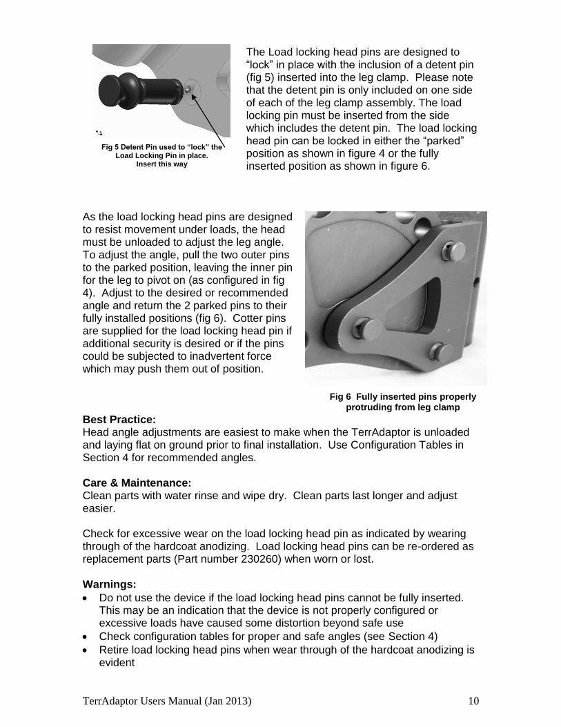
ability to adjust the head angle in multiple directions. This allows the head to remain level even when the terrain is not. A level head means that rigging attached is clean, safe, and organized. The main head and the half plate each have 10 oval shaped holes on the outside curve which serve as adjustment holes. The inner 6 holes are marked A through F for angle reference purposes. Head angle adjustments are achieved by pivoting leg clamps to desired angles A through F and locking in place by using three Load Locking Head Pins.
Fig 5
Fig 4 Load Locking Head Pins (Parked position)
Fig 4 Load Locking Head Pins(Parked position)
TerrAdaptor Users Manual (Jan 2013) 10
The Load locking head pins are designed to “lock” in place with the inclusion of a detent pin (fig 5) inserted into the leg clamp. Please note that the detent pin is only included on one side of each of the leg clamp assembly. The load locking pin must be inserted from the side which includes the detent pin. The load locking head pin can be locked in either the “parked” position as shown in figure 4 or the fully inserted position as shown in figure 6.
As the load locking head pins are designed to resist movement under loads, the head must be unloaded to adjust the leg angle. To adjust the angle, pull the two outer pins to the parked position, leaving the inner pin for the leg to pivot on (as configured in fig 4). Adjust to the desired or recommended angle and return the 2 parked pins to their fully installed positions (fig 6). Cotter pins are supplied for the load locking head pin if additional security is desired or if the pins could be subjected to inadvertent force which may push them out of position. Best Practice: Head angle adjustments are easiest to make when the TerrAdaptor is unloaded and laying flat on ground prior to final installation. Use Configuration Tables in Section 4 for recommended angles. Care & Maintenance: Clean parts with water rinse and wipe dry. Clean parts last longer and adjust easier. Check for excessive wear on the load locking head pin as indicated by wearing through of the hardcoat anodizing. Load locking head pins can be re-ordered as replacement parts (Part number 230260) when worn or lost. Warnings:
Do not use the device if the load locking head pins cannot be fully inserted. This may be an indication that the device is not properly configured or excessive loads have caused some distortion beyond safe use
Check configuration tables for proper and safe angles (see Section 4)
Retire load locking head pins when wear through of the hardcoat anodizing is evident
Fig 5 Detent Pin used to “lock” the
Load Locking Pin in place. Insert this way
Fig 6 Fully inserted pins properly protruding from leg clamp
TerrAdaptor Users Manual (Jan 2013) 11
Fig 7 Offset Leg Clamps (left-facing forward; right-facing backwards) for illustrative purposes. Best practices has both offset leg clamps facing forward in a typical tripod configuration set up
Fig 8 Rear leg with centered leg clamp. Legs are able to by-pass each other due to offset leg clamp orientation
Leg Clamps
Leg Clamps are the means of attaching leg sections to the main head of the TerrAdaptor. Two types of clamps, Centered and Offset, are used in the tripod configuration. Although the different style leg clamps are safe to use in any position, the centered clamp is most commonly used on the rear leg (fig 8), while the offset clamps are used in the side legs. For the typical tripod setup the offset clamps
are oriented with the offset leg tubes facing forward (away from the rear leg) providing the most stable and symmetric configuration. In some setups, for space or rigging considerations, it may be desirable for both side legs to extend through the head. In this case, set one side leg clamp facing forward and the other backwards so that leg tubes may bypass each other without interference (fig 8). This alternating forward and backward leg clamp arrangement is also ideal for rigging sideways A-Frames with greater stability and a greater working area under the head. The perf leg tubes slide through the leg clamps and are secured in position by using the leg coupling pin. Leg clamps are attached to the head by means of 3 load locking head pins as shown in figure 6. Best Practice: Use centered leg clamp on the rear leg and set both offset leg clamps facing forward when configuring as a standard tripod. For symmetric or edge-A tripods use centered leg clamp on the rear leg and set both offset leg clamps facing forward on the side legs. For sideways A-frames use alternating forward and backward facing leg clamps.
TerrAdaptor Users Manual (Jan 2013) 12
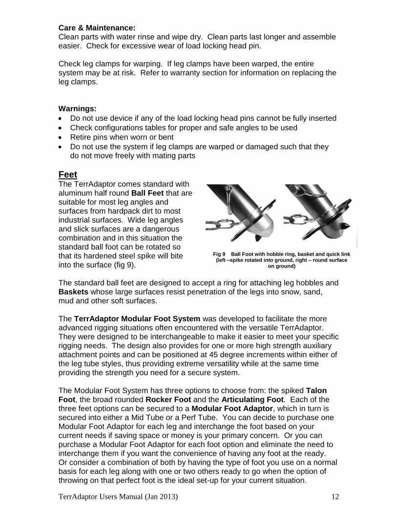
Fig 9 Ball Foot with hobble ring, basket and quick link (left –spike rotated into ground, right – round surface
on ground)
Care & Maintenance: Clean parts with water rinse and wipe dry. Clean parts last longer and assemble easier. Check for excessive wear of load locking head pin. Check leg clamps for warping. If leg clamps have been warped, the entire system may be at risk. Refer to warranty section for information on replacing the leg clamps. Warnings:
Do not use device if any of the load locking head pins cannot be fully inserted
Check configurations tables for proper and safe angles to be used
Retire pins when worn or bent
Do not use the system if leg clamps are warped or damaged such that they do not move freely with mating parts
Feet The TerrAdaptor comes standard with aluminum half round Ball Feet that are suitable for most leg angles and surfaces from hardpack dirt to most industrial surfaces. Wide leg angles and slick surfaces are a dangerous combination and in this situation the standard ball foot can be rotated so that its hardened steel spike will bite into the surface (fig 9). The standard ball feet are designed to accept a ring for attaching leg hobbles and Baskets whose large surfaces resist penetration of the legs into snow, sand, mud and other soft surfaces. The TerrAdaptor Modular Foot System was developed to facilitate the more advanced rigging situations often encountered with the versatile TerrAdaptor. They were designed to be interchangeable to make it easier to meet your specific rigging needs. The design also provides for one or more high strength auxiliary attachment points and can be positioned at 45 degree increments within either of the leg tube styles, thus providing extreme versatility while at the same time providing the strength you need for a secure system. The Modular Foot System has three options to choose from: the spiked Talon Foot, the broad rounded Rocker Foot and the Articulating Foot. Each of the three feet options can be secured to a Modular Foot Adaptor, which in turn is secured into either a Mid Tube or a Perf Tube. You can decide to purchase one Modular Foot Adaptor for each leg and interchange the foot based on your current needs if saving space or money is your primary concern. Or you can purchase a Modular Foot Adaptor for each foot option and eliminate the need to interchange them if you want the convenience of having any foot at the ready. Or consider a combination of both by having the type of foot you use on a normal basis for each leg along with one or two others ready to go when the option of throwing on that perfect foot is the ideal set-up for your current situation.
TerrAdaptor Users Manual (Jan 2013) 13
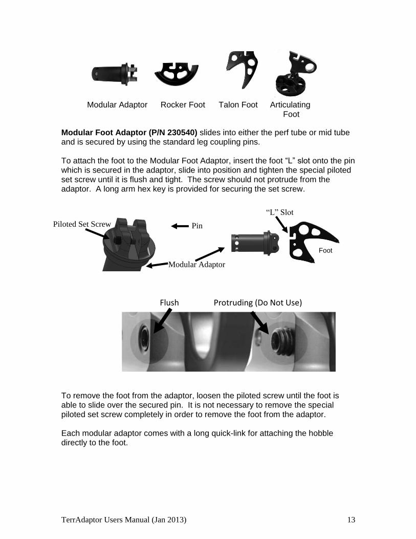
Modular Foot Adaptor (P/N 230540) slides into either the perf tube or mid tube and is secured by using the standard leg coupling pins. To attach the foot to the Modular Foot Adaptor, insert the foot “L” slot onto the pin which is secured in the adaptor, slide into position and tighten the special piloted set screw until it is flush and tight. The screw should not protrude from the adaptor. A long arm hex key is provided for securing the set screw. To remove the foot from the adaptor, loosen the piloted screw until the foot is able to slide over the secured pin. It is not necessary to remove the special piloted set screw completely in order to remove the foot from the adaptor. Each modular adaptor comes with a long quick-link for attaching the hobble directly to the foot.
Modular Adaptor Rocker Foot Talon Foot Articulating Foot
Pin Piloted Set Screw
Modular Adaptor
Flush Protruding (Do Not Use)
Foot
“L” Slot
TerrAdaptor Users Manual (Jan 2013) 14
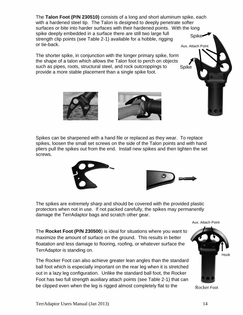
The Talon Foot (P/N 230510) consists of a long and short aluminum spike, each with a hardened steel tip. The Talon is designed to deeply penetrate softer surfaces or bite into harder surfaces with their hardened points. With the long spike deeply embedded in a surface there are still two large full strength clip points (see Table 2-1) available for a hobble, rigging or tie-back. The shorter spike, in conjunction with the longer primary spike, form the shape of a talon which allows the Talon foot to perch on objects such as pipes, roots, structural steel, and rock outcroppings to provide a more stable placement than a single spike foot.
Spikes can be sharpened with a hand file or replaced as they wear. To replace spikes, loosen the small set screws on the side of the Talon points and with hand pliers pull the spikes out from the end. Install new spikes and then tighten the set screws. The spikes are extremely sharp and should be covered with the provided plastic protectors when not in use. If not packed carefully, the spikes may permanently damage the TerrAdaptor bags and scratch other gear. The Rocket Foot (P/N 230500) is ideal for situations where you want to
maximize the amount of surface on the ground. This results in better
floatation and less damage to flooring, roofing, or whatever surface the
TerrAdaptor is standing on.
The Rocker Foot can also achieve greater lean angles than the standard
ball foot which is especially important on the rear leg when it is stretched
out in a lazy leg configuration. Unlike the standard ball foot, the Rocker
Foot has two full strength auxiliary attach points (see Table 2-1) that can
be clipped even when the leg is rigged almost completely flat to the
Spike
Spike
Aux. Attach Point
Hook
Aux. Attach Point
Rocker Foot
Hook
TerrAdaptor Users Manual (Jan 2013) 15
ground. It is important to note that the rocker is not symmetric so it may need to
be flipped to reach the highest lean angles. The non-symmetric design also
forms a hook arm that helps create a more rigid tie-in to objects such as angle
iron or plate.
With a rubber pad and a swiveling ball socket, the Articulating Foot (P/N 230530) is ideal for use on hard flat surfaces such as concrete or flooring as it provides a slip resistant placement that is less likely to damage the surface. Holes are also provided in the flat base for attaching directly to the surface by means of inserting screws, bolts, or driven spikes. If the angle between the leg and the surface does not allow the base of the articulating foot to rest flat on the surface, the base needs to be rotated to align the notch which allows the base to rest flat on the surface. If the base does not rest completely flat against the surface, relatively light loads will damage the ball socket joint and/or could cause complete failure of the socket joint resulting in the base being detached from the TerrAdaptor. The articulating foot provides for three large holes directly on the foot for lashing, as well as a single high strength auxiliary attachment point on the adaptor plate (see Table 2-1). Best Practice: Select the feet option (use of ball foot, or one of the three modular foot options) and foot position before setting up the tripod. The feet are not easily exchanged once the TerrAdaptor is loaded or the hobbles have been tighten. Evaluate the forces that the modular feet could be exposed to and review Table 2-1. Consider other rigging methods if forces approach or exceed the stated breaking strength. Securing the feet directly to anchors will create a more rigid setup and should be done when possible. Care & Maintenance: The feet, hobble plate and quick link can be cleaned with a water rinse and simple wipe dry. Check all components for bending and warping which could indicate overloading.
TerrAdaptor Users Manual (Jan 2013) 16
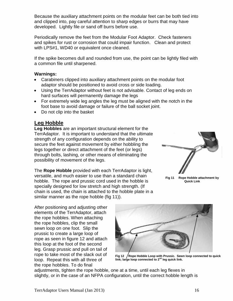
Fig 11 Rope Hobble attachment by
Quick Link
Fig 12 Rope Hobble Loop with Prussic. Sewn loop connected to quick link; large loop connected to 2
nd leg quick link.
Because the auxiliary attachment points on the modular feet can be both tied into and clipped into, pay careful attention to sharp edges or burrs that may have developed. Lightly file or sand off burrs before use.
Periodically remove the feet from the Modular Foot Adaptor. Check fasteners and spikes for rust or corrosion that could impair function. Clean and protect with LPS#1, WD40 or equivalent once cleaned. If the spike becomes dull and rounded from use, the point can be lightly filed with a common file until sharpened. Warnings:
Carabiners clipped into auxiliary attachment points on the modular foot adaptor should be positioned to avoid cross or side loading.
Using the TerrAdaptor without feet is not advisable. Contact of leg ends on hard surfaces will permanently damage the legs
For extremely wide leg angles the leg must be aligned with the notch in the foot base to avoid damage or failure of the ball socket joint.
Do not clip into the basket
Leg Hobble Leg Hobbles are an important structural element for the TerrAdaptor. It is important to understand that the ultimate strength of any configuration depends on the ability to secure the feet against movement by either hobbling the legs together or direct attachment of the feet (or legs) through bolts, lashing, or other means of eliminating the possibility of movement of the legs. The Rope Hobble provided with each TerrAdaptor is light, versatile, and much easier to use than a standard chain hobble. The rope and prussic cord used in the hobble is specially designed for low stretch and high strength. (If chain is used, the chain is attached to the hobble plate in a similar manner as the rope hobble (fig 11)). After positioning and adjusting other elements of the TerrAdaptor, attach the rope hobbles. When attaching the rope hobbles, clip the small sewn loop on one foot. Slip the prussic to create a large loop of rope as seen in figure 12 and attach this loop at the foot of the second leg. Grasp prussic and pull on tail of rope to take most of the slack out of loop. Repeat this with all three of the rope hobbles. To do final adjustments, tighten the rope hobble, one at a time, until each leg flexes in slightly, or in the case of an NFPA configuration, until the correct hobble length is
TerrAdaptor Users Manual (Jan 2013) 17
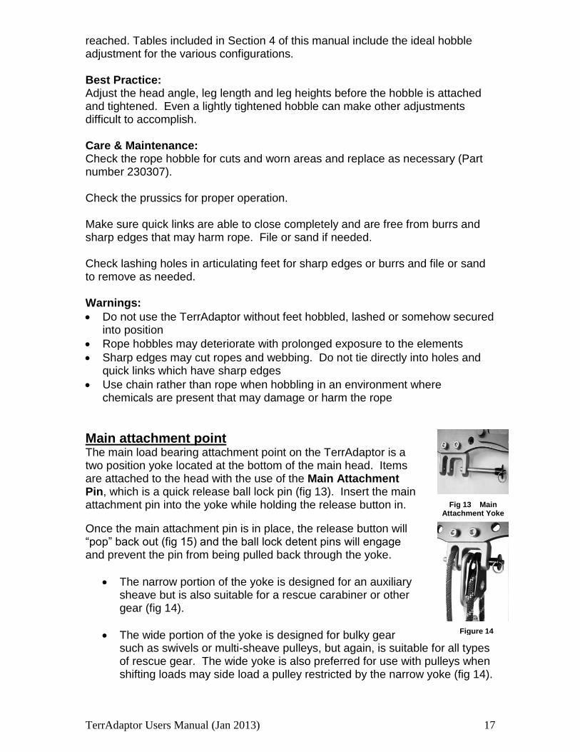
Figure 14
Fig 13 Main
Attachment Yoke
reached. Tables included in Section 4 of this manual include the ideal hobble adjustment for the various configurations. Best Practice: Adjust the head angle, leg length and leg heights before the hobble is attached and tightened. Even a lightly tightened hobble can make other adjustments difficult to accomplish. Care & Maintenance: Check the rope hobble for cuts and worn areas and replace as necessary (Part number 230307). Check the prussics for proper operation. Make sure quick links are able to close completely and are free from burrs and sharp edges that may harm rope. File or sand if needed. Check lashing holes in articulating feet for sharp edges or burrs and file or sand to remove as needed. Warnings:
Do not use the TerrAdaptor without feet hobbled, lashed or somehow secured into position
Rope hobbles may deteriorate with prolonged exposure to the elements
Sharp edges may cut ropes and webbing. Do not tie directly into holes and quick links which have sharp edges
Use chain rather than rope when hobbling in an environment where chemicals are present that may damage or harm the rope
Main attachment point The main load bearing attachment point on the TerrAdaptor is a two position yoke located at the bottom of the main head. Items are attached to the head with the use of the Main Attachment Pin, which is a quick release ball lock pin (fig 13). Insert the main attachment pin into the yoke while holding the release button in.
Once the main attachment pin is in place, the release button will “pop” back out (fig 15) and the ball lock detent pins will engage and prevent the pin from being pulled back through the yoke.
The narrow portion of the yoke is designed for an auxiliary sheave but is also suitable for a rescue carabiner or other gear (fig 14).
The wide portion of the yoke is designed for bulky gear such as swivels or multi-sheave pulleys, but again, is suitable for all types of rescue gear. The wide yoke is also preferred for use with pulleys when shifting loads may side load a pulley restricted by the narrow yoke (fig 14).
TerrAdaptor Users Manual (Jan 2013) 18
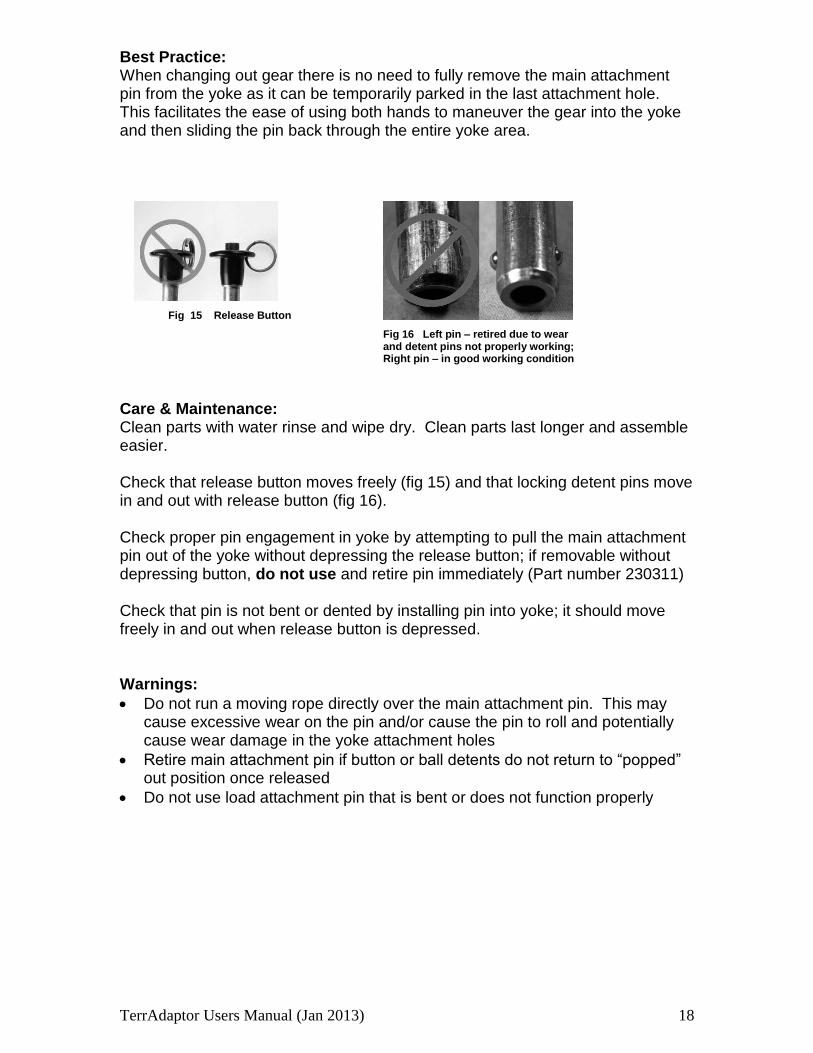
Fig 16 Left pin – retired due to wear and detent pins not properly working; Right pin – in good working condition
Fig 15 Release Button
Fig 6 3
Best Practice: When changing out gear there is no need to fully remove the main attachment pin from the yoke as it can be temporarily parked in the last attachment hole. This facilitates the ease of using both hands to maneuver the gear into the yoke and then sliding the pin back through the entire yoke area.
Care & Maintenance: Clean parts with water rinse and wipe dry. Clean parts last longer and assemble easier. Check that release button moves freely (fig 15) and that locking detent pins move in and out with release button (fig 16). Check proper pin engagement in yoke by attempting to pull the main attachment pin out of the yoke without depressing the release button; if removable without depressing button, do not use and retire pin immediately (Part number 230311) Check that pin is not bent or dented by installing pin into yoke; it should move freely in and out when release button is depressed. Warnings:
Do not run a moving rope directly over the main attachment pin. This may cause excessive wear on the pin and/or cause the pin to roll and potentially cause wear damage in the yoke attachment holes
Retire main attachment pin if button or ball detents do not return to “popped” out position once released
Do not use load attachment pin that is bent or does not function properly
TerrAdaptor Users Manual (Jan 2013) 19
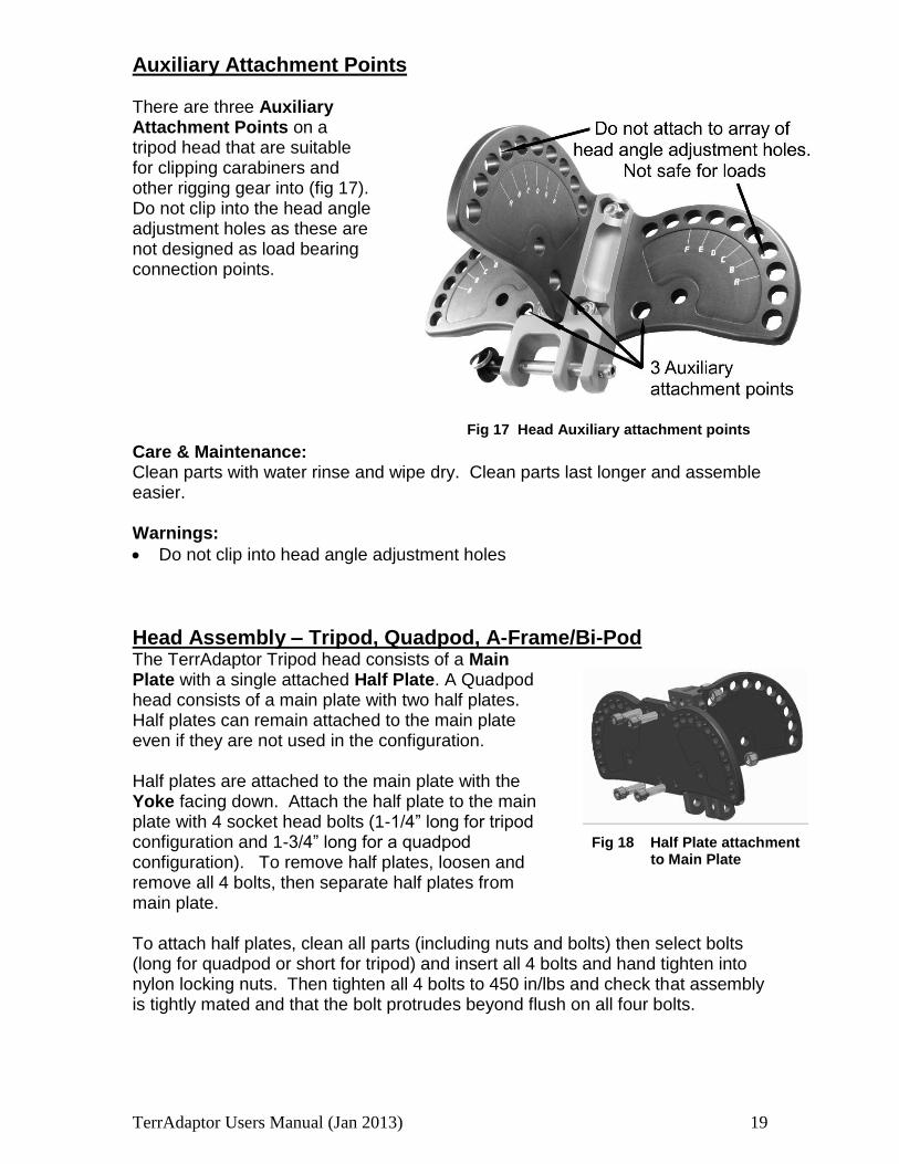
Fig 18 Half Plate attachment to Main Plate
Fig 17 Head Auxiliary attachment points
Auxiliary Attachment Points There are three Auxiliary Attachment Points on a tripod head that are suitable for clipping carabiners and other rigging gear into (fig 17). Do not clip into the head angle adjustment holes as these are not designed as load bearing connection points. Care & Maintenance: Clean parts with water rinse and wipe dry. Clean parts last longer and assemble easier. Warnings:
Do not clip into head angle adjustment holes
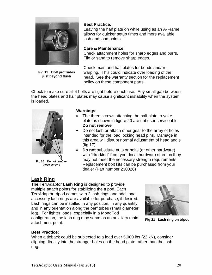
Head Assembly – Tripod, Quadpod, A-Frame/Bi-Pod The TerrAdaptor Tripod head consists of a Main Plate with a single attached Half Plate. A Quadpod head consists of a main plate with two half plates. Half plates can remain attached to the main plate even if they are not used in the configuration. Half plates are attached to the main plate with the Yoke facing down. Attach the half plate to the main plate with 4 socket head bolts (1-1/4” long for tripod configuration and 1-3/4” long for a quadpod configuration). To remove half plates, loosen and remove all 4 bolts, then separate half plates from main plate. To attach half plates, clean all parts (including nuts and bolts) then select bolts (long for quadpod or short for tripod) and insert all 4 bolts and hand tighten into nylon locking nuts. Then tighten all 4 bolts to 450 in/lbs and check that assembly is tightly mated and that the bolt protrudes beyond flush on all four bolts.
TerrAdaptor Users Manual (Jan 2013) 20
Fig 21 Lash ring on tripod
Fig 20 Do not remove these screws
Best Practice: Leaving the half plate on while using as an A-Frame allows for quicker setup times and more available lash and load points. Care & Maintenance: Check attachment holes for sharp edges and burrs. File or sand to remove sharp edges. Check main and half plates for bends and/or warping. This could indicate over loading of the head. See the warranty section for the replacement policy on these component parts.
Check to make sure all 4 bolts are tight before each use. Any small gap between the head plates and half plates may cause significant instability when the system is loaded.
Warnings:
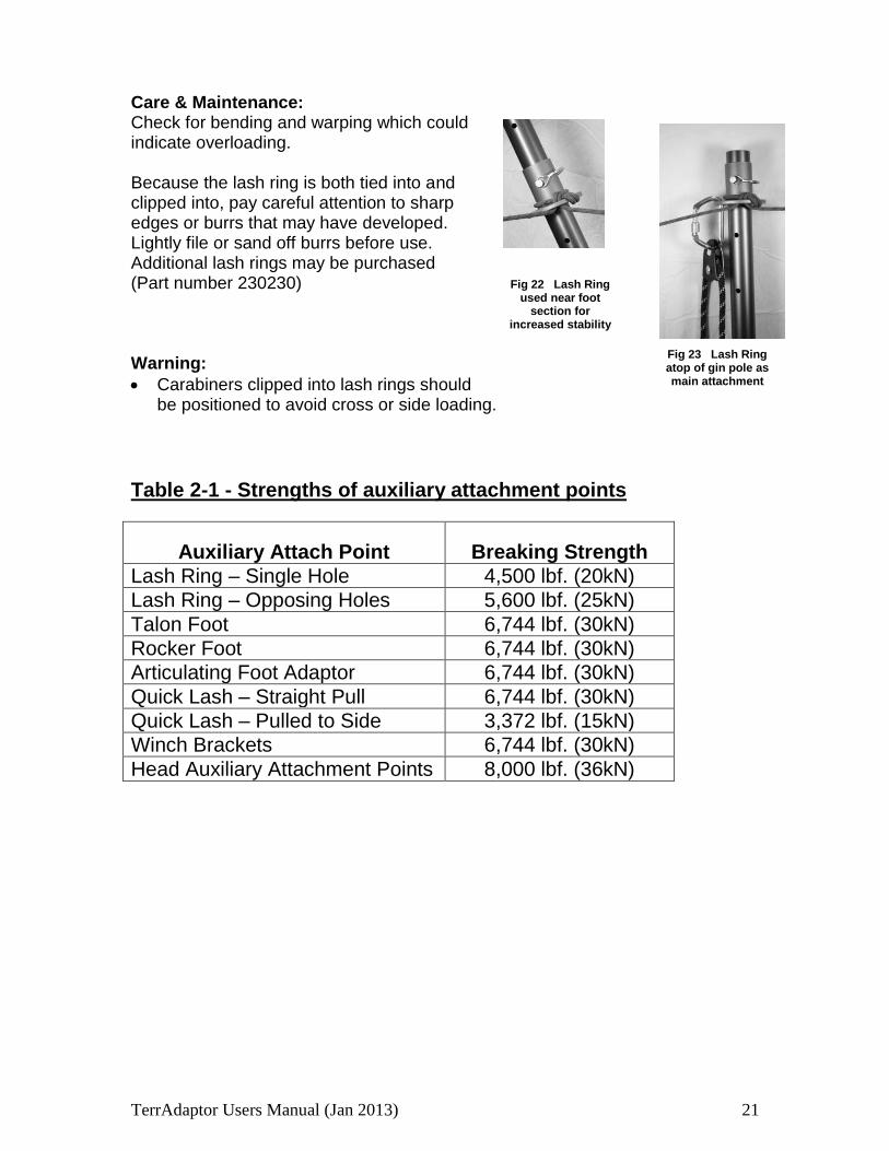
The three screws attaching the half plate to yoke plate as shown in figure 20 are not user serviceable. Do not remove
Do not lash or attach other gear to the array of holes intended for the load locking head pins. Damage in this area will disrupt normal adjustment of head angle (fig 17)
Do not substitute nuts or bolts (or other hardware) with “like-kind” from your local hardware store as they may not meet the necessary strength requirements. Replacement bolt kits can be purchased from your dealer (Part number 230326)
Lash Ring The TerrAdaptor Lash Ring is designed to provide multiple attach points for stabilizing the tripod. Each TerrAdaptor tripod comes with 2 lash rings and additional accessory lash rings are available for purchase, if desired. Lash rings can be installed in any position, in any quantity and in any orientation along the perf tubes (small diameter leg). For lighter loads, especially in a MonoPod configuration, the lash ring may serve as an auxiliary main attachment point. Best Practice: When a tieback could be subjected to a load over 5,000 lbs (22 kN), consider clipping directly into the stronger holes on the head plate rather than the lash ring.
Fig 19 Bolt protrudes
just beyond flush
TerrAdaptor Users Manual (Jan 2013) 21
Fig 22 Lash Ring used near foot
section for increased stability
Fig 23 Lash Ring atop of gin pole as main attachment
Care & Maintenance: Check for bending and warping which could indicate overloading. Because the lash ring is both tied into and clipped into, pay careful attention to sharp edges or burrs that may have developed. Lightly file or sand off burrs before use. Additional lash rings may be purchased (Part number 230230) Warning:
Carabiners clipped into lash rings should be positioned to avoid cross or side loading.
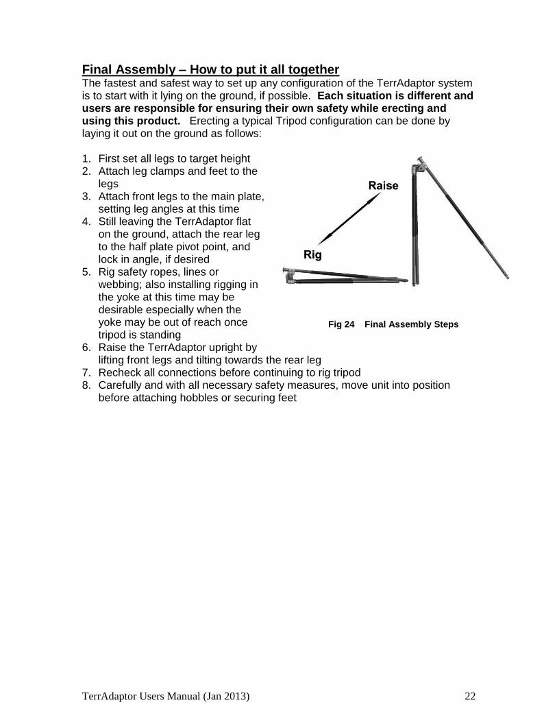
Table 2-1 - Strengths of auxiliary attachment points
Auxiliary Attach Point Breaking Strength
Lash Ring – Single Hole 4,500 lbf. (20kN)
Lash Ring – Opposing Holes 5,600 lbf. (25kN)
Talon Foot 6,744 lbf. (30kN)
Rocker Foot 6,744 lbf. (30kN)
Articulating Foot Adaptor 6,744 lbf. (30kN)
Quick Lash – Straight Pull 6,744 lbf. (30kN)
Quick Lash – Pulled to Side 3,372 lbf. (15kN)
Winch Brackets 6,744 lbf. (30kN)
Head Auxiliary Attachment Points 8,000 lbf. (36kN)
TerrAdaptor Users Manual (Jan 2013) 22
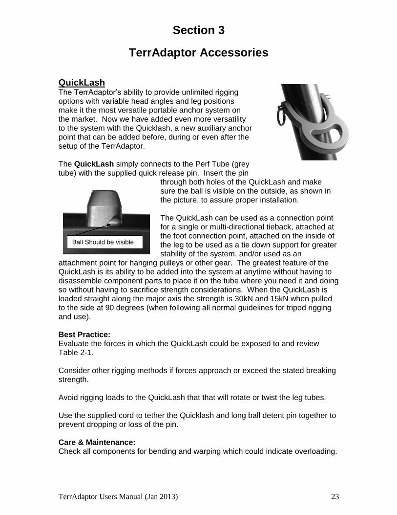
Fig 24 Final Assembly Steps
Final Assembly – How to put it all together The fastest and safest way to set up any configuration of the TerrAdaptor system is to start with it lying on the ground, if possible. Each situation is different and users are responsible for ensuring their own safety while erecting and using this product. Erecting a typical Tripod configuration can be done by laying it out on the ground as follows: 1. First set all legs to target height 2. Attach leg clamps and feet to the
legs 3. Attach front legs to the main plate,
setting leg angles at this time 4. Still leaving the TerrAdaptor flat
on the ground, attach the rear leg to the half plate pivot point, and lock in angle, if desired
5. Rig safety ropes, lines or webbing; also installing rigging in the yoke at this time may be desirable especially when the yoke may be out of reach once tripod is standing
6. Raise the TerrAdaptor upright by lifting front legs and tilting towards the rear leg
7. Recheck all connections before continuing to rig tripod 8. Carefully and with all necessary safety measures, move unit into position
before attaching hobbles or securing feet

TerrAdaptor Users Manual (Jan 2013) 23
Section 3
TerrAdaptor Accessories
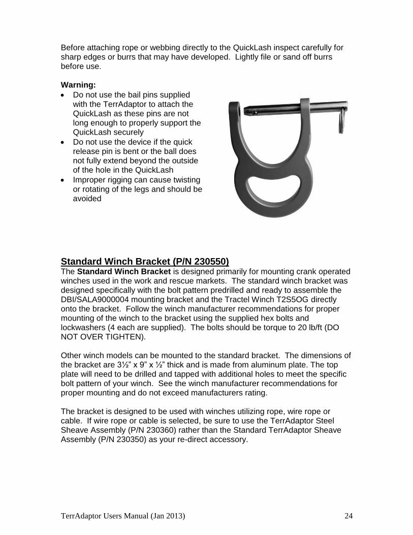
QuickLash The TerrAdaptor’s ability to provide unlimited rigging options with variable head angles and leg positions make it the most versatile portable anchor system on the market. Now we have added even more versatility to the system with the Quicklash, a new auxiliary anchor point that can be added before, during or even after the setup of the TerrAdaptor. The QuickLash simply connects to the Perf Tube (grey tube) with the supplied quick release pin. Insert the pin
through both holes of the QuickLash and make sure the ball is visible on the outside, as shown in the picture, to assure proper installation. The QuickLash can be used as a connection point for a single or multi-directional tieback, attached at the foot connection point, attached on the inside of the leg to be used as a tie down support for greater stability of the system, and/or used as an
attachment point for hanging pulleys or other gear. The greatest feature of the QuickLash is its ability to be added into the system at anytime without having to disassemble component parts to place it on the tube where you need it and doing so without having to sacrifice strength considerations. When the QuickLash is loaded straight along the major axis the strength is 30kN and 15kN when pulled to the side at 90 degrees (when following all normal guidelines for tripod rigging and use).
Best Practice: Evaluate the forces in which the QuickLash could be exposed to and review Table 2-1. Consider other rigging methods if forces approach or exceed the stated breaking strength. Avoid rigging loads to the QuickLash that that will rotate or twist the leg tubes. Use the supplied cord to tether the Quicklash and long ball detent pin together to prevent dropping or loss of the pin. Care & Maintenance: Check all components for bending and warping which could indicate overloading.
Ball Should be visible
TerrAdaptor Users Manual (Jan 2013) 24
Before attaching rope or webbing directly to the QuickLash inspect carefully for sharp edges or burrs that may have developed. Lightly file or sand off burrs before use. Warning:
Do not use the bail pins supplied with the TerrAdaptor to attach the QuickLash as these pins are not long enough to properly support the QuickLash securely
Do not use the device if the quick release pin is bent or the ball does not fully extend beyond the outside of the hole in the QuickLash
Improper rigging can cause twisting or rotating of the legs and should be avoided
Standard Winch Bracket (P/N 230550) The Standard Winch Bracket is designed primarily for mounting crank operated winches used in the work and rescue markets. The standard winch bracket was designed specifically with the bolt pattern predrilled and ready to assemble the DBI/SALA9000004 mounting bracket and the Tractel Winch T2S5OG directly onto the bracket. Follow the winch manufacturer recommendations for proper mounting of the winch to the bracket using the supplied hex bolts and lockwashers (4 each are supplied). The bolts should be torque to 20 lb/ft (DO NOT OVER TIGHTEN). Other winch models can be mounted to the standard bracket. The dimensions of the bracket are 3½” x 9” x ½” thick and is made from aluminum plate. The top plate will need to be drilled and tapped with additional holes to meet the specific bolt pattern of your winch. See the winch manufacturer recommendations for proper mounting and do not exceed manufacturers rating. The bracket is designed to be used with winches utilizing rope, wire rope or cable. If wire rope or cable is selected, be sure to use the TerrAdaptor Steel Sheave Assembly (P/N 230360) rather than the Standard TerrAdaptor Sheave Assembly (P/N 230350) as your re-direct accessory.

TerrAdaptor Users Manual (Jan 2013) 25
Capstan Winch Bracket (P/N 230551) The Capstan Winch Bracket is designed specifically for mounting a Harken 40 ST or 40.2 ST capstan winch. The top plate is predrilled and ready for assembly. Follow the Harken recommendations for proper mounting of the winch to the bracket using the supplied stainless cap screws, washers and hex nuts (5 each). The screws should be torque to 6 or 7 lb/ft (DO NOT OVER TIGHTEN). The TerrAdaptor Capstan Winch Bracket employs a lightweight stainless loop that guides the rope into the capstan at the correct angle for maximum grip of the rope. The guide loop can also mind prussics which can simplify progress capture rigging.
Attaching The Winch Bracket to the TerrAdaptor System The bracket is normally located on the rear leg of a tripod, but it can be located on any leg provided the rope or cable is safely routed. It can be attached anywhere along the smaller diameter Perf Tube. It can also be attached at the junction between the Perf Tube and larger Mid Tube by lining up the relief in the sideplates of the bracket at the junction of the two tubes as shown in the picture below. Once positioned, insert the three long quick release pins (with rings) so that the ball detent is fully exposed on the opposite side as shown in the picture below.
The bracket also has high strength auxiliary attach points (see Table 2-1) at each end for rigging belays, progress capture, tie down, and other rigging needs.
Capstan Winch System
The Capstan Winch System comes fully assembled with the Harken 40.2 ST two speed winch, including the Harken 10 inch lock-in aluminum speed grip handle. Simply attach the assembly to the TerrAdaptor leg with the long quick release pins as described above. For more information on the Harken winch go to www.harken.com.
Ball should be visible Attached at Junction
TerrAdaptor Users Manual (Jan 2013) 26
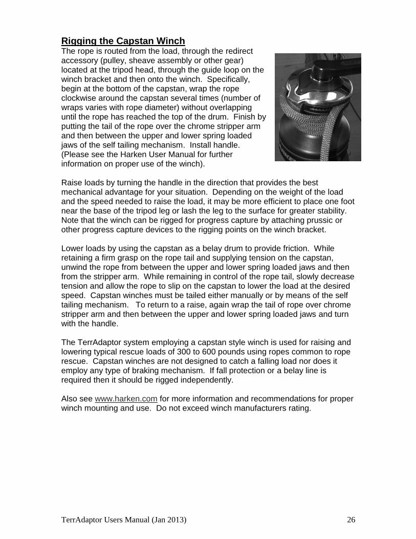
Rigging the Capstan Winch The rope is routed from the load, through the redirect accessory (pulley, sheave assembly or other gear) located at the tripod head, through the guide loop on the winch bracket and then onto the winch. Specifically, begin at the bottom of the capstan, wrap the rope clockwise around the capstan several times (number of wraps varies with rope diameter) without overlapping until the rope has reached the top of the drum. Finish by putting the tail of the rope over the chrome stripper arm and then between the upper and lower spring loaded jaws of the self tailing mechanism. Install handle. (Please see the Harken User Manual for further information on proper use of the winch). Raise loads by turning the handle in the direction that provides the best mechanical advantage for your situation. Depending on the weight of the load and the speed needed to raise the load, it may be more efficient to place one foot near the base of the tripod leg or lash the leg to the surface for greater stability. Note that the winch can be rigged for progress capture by attaching prussic or other progress capture devices to the rigging points on the winch bracket. Lower loads by using the capstan as a belay drum to provide friction. While retaining a firm grasp on the rope tail and supplying tension on the capstan, unwind the rope from between the upper and lower spring loaded jaws and then from the stripper arm. While remaining in control of the rope tail, slowly decrease tension and allow the rope to slip on the capstan to lower the load at the desired speed. Capstan winches must be tailed either manually or by means of the self tailing mechanism. To return to a raise, again wrap the tail of rope over chrome stripper arm and then between the upper and lower spring loaded jaws and turn with the handle. The TerrAdaptor system employing a capstan style winch is used for raising and lowering typical rescue loads of 300 to 600 pounds using ropes common to rope rescue. Capstan winches are not designed to catch a falling load nor does it employ any type of braking mechanism. If fall protection or a belay line is required then it should be rigged independently. Also see www.harken.com for more information and recommendations for proper winch mounting and use. Do not exceed winch manufacturers rating.
TerrAdaptor Users Manual (Jan 2013) 27
Best Practice: Cable winches should be mounted on the inside of the tripod so the cable does not drag on the leg tubes. Capstan winches are easier to operate when they are mounted on the outside of the leg and ropes will not damage leg tubes during operation. When possible, secure feet directly to anchors to create a more rigid setup. Care & Maintenance: Check all components for bending and warping which could indicate overloading. Auxiliary attach points can be both tied into and clipped into. As a result, pay careful attention to sharp edges or burrs that may have developed. Lightly file or sand off burrs before use. Warnings:
Carabiners clipped into auxiliary attach points should be positioned to avoid cross or side loading
Do not use the normal leg coupling pins to attach the winch bracket as they are too short and could result in the winch bracket detaching from the leg and resulting in injury or death
See winch manufacturers recommendations for proper winch mounting and do not exceed manufacturers rating when operating winches
Failure to maintain control of the rope tail on Capstan winches could result in injury or death due to falls

TerrAdaptor Users Manual (Jan 2013) 28
Section 4
Configurations and Set-up Tables
Standard Configurations The TerrAdaptor is both very modular and highly adjustable, lending itself to an almost unimaginable number of configurations. We have identified and tested a core group of configurations that we feel addresses a broad range of rope rescue applications. By providing this information we hope that users will find configurations that fit their needs as well as provide a basis for developing new configurations. As with any piece of rope rescue gear, the user is ultimately responsible for ensuring that it meets their safety and performance requirements. The following section outlines the core group of configurations and provides the TerrAdaptor settings used to achieve the configurations. Each table includes the required setting for head angles, leg height adjustment references, and hobble lengths to achieve various heights. The table also identifies the manufacturers tested breaking strength of the system at the acquired height. The height indicated on the table is the height from the ground to the main attachment point and is expressed in feet. If there is “N/A” in the leg section, then the third or fourth leg is not needed to achieve the designated height. For example, to achieve the 5-foot height, only the first two legs are needed and they are joined at Y4. If a 7-foot height were desired three tubes would be required. Also note that the main plate head angle settings are expressed with 2 listings for both the left and right hand side of the head. In all of the examples listed below, the angles are the same on both sides of the head, but this may not always be the case in the field.
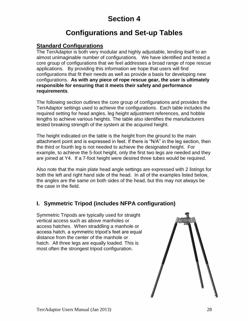
I. Symmetric Tripod (includes NFPA configuration) Symmetric Tripods are typically used for straight vertical access such as above manholes or access hatches. When straddling a manhole or access hatch, a symmetric tripod’s feet are equal distance from the center of the manhole or hatch. All three legs are equally loaded. This is most often the strongest tripod configuration.
Fig 6 4

TerrAdaptor Users Manual (Jan 2013) 29
Table 4-1
Symmetric Tripod Main Plate Head Angle Settings - A/A
Half Plate Head Angle Settings - B
Height
Upper Section
Coupling
Lower Section
Coupling
Optional Section
Coupling Hobble Length
Breaking Strength
Applicable Standards
4 X7 n/a n/a 42” 12,200 NFPA, ASTM
5 Y4 n/a n/a 54” 12,000 NFPA, ASTM
6 X2 n/a n/a 60” 9,300 NFPA, ASTM
7 Y7 X9 n/a 69” 12,100 NFPA, ASTM
8 X5 X9 n/a 70” 8,000 NFPA, ASTM
9 Y2 X9 n/a 78” 7,000 ASTM
10 X1 X9 n/a 78” 7,000 ASTM
11 X6 X9 X1 78” 7,000 ASTM
12 Y3 X9 X1 78” 5,600 ASTM
13 X1 X9 X1 78” 4,600
How Head angles affect tripod strength There are many factors that go into the proper set-up and stability of a tripod system, which is why intensive personal training is required with the TerrAdaptor. Two of the main factors affecting the total strength and safety of a placement are the head angle used and the overall height of the system. As a guideline, for a given height, the wider the head angles the lower the strength. For example, the following table shows how a 7-foot tripod breaking strength declines from 12,100 lbf. to 7,700 lbf. just by slightly increasing the head angle.

TerrAdaptor Users Manual (Jan 2013) 30
Table 4-2
Symmetric Tripod setup angle comparison
Height Ma
in P
late
He
ad
An
gle
se
ttin
g
Half P
late
He
ad
An
gle
se
ttin
g
Upper Section
Coupling
Lower Section
Coupling Hobble Length
Breaking Strength A
pp
lica
ble
Sta
nd
ard
s
7’ A/A B Y7 X9 Tight 12,100 NFPA, ASTM
7’ B/B C Front – X5 Rear – Y6
Front – X9 Rear – X9
Tight 10,100 ASTM
7’ C/C D Front – Y2 Rear – X6
Front – X9 Rear – X9
Tight 7,700 ASTM
Wide Tripod Configurations In many cases a wide and more stable configuration is desirable even at the expense of breaking strength. Wide configurations also offer a larger work area under the tripod. The following table shows strength of a few wide stable configurations which have very large work areas. Table 4-3
Symmetric Tripod – Wide setup
Height Ma
in P
late
He
ad
An
gle
se
ttin
g
Half P
late
He
ad
An
gle
se
ttin
g
Upper Section
Coupling
Upper Section
Coupling Hobble Length
Breaking Strength A
pp
lica
ble
Sta
nd
ard
s
7’ B/B C Front – X5 Rear – Y6
Front – X9 Rear – X9
Tight 10,100 ASTM
8’ B/B C Front – Y2 Rear – Y4
Front – X9 Rear – X9
Tight 9,600 ASTM
8 ½’ B/B C Front – X1 Rear – X3
Front – X9 Rear – X9
Tight 8,300 ASTM
TerrAdaptor Users Manual (Jan 2013) 31
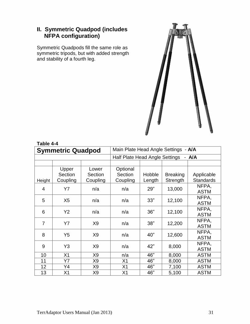
II. Symmetric Quadpod (includes NFPA configuration)
Symmetric Quadpods fill the same role as symmetric tripods, but with added strength and stability of a fourth leg. Table 4-4
Symmetric Quadpod Main Plate Head Angle Settings - A/A
Half Plate Head Angle Settings - A/A
Height
Upper Section
Coupling
Lower Section
Coupling
Optional Section
Coupling Hobble Length
Breaking Strength
Applicable Standards
4 Y7 n/a n/a 29” 13,000 NFPA, ASTM
5 X5 n/a n/a 33” 12,100 NFPA, ASTM
6 Y2 n/a n/a 36” 12,100 NFPA, ASTM
7 Y7 X9 n/a 38” 12,200 NFPA, ASTM
8 Y5 X9 n/a 40” 12,600 NFPA, ASTM
9 Y3 X9 n/a 42” 8,000 NFPA, ASTM
10 X1 X9 n/a 46” 8,000 ASTM
11 Y7 X9 X1 46” 8,000 ASTM
12 Y4 X9 X1 46” 7,100 ASTM
13 X1 X9 X1 46” 5,100 ASTM
Fig 6 5
TerrAdaptor Users Manual (Jan 2013) 32
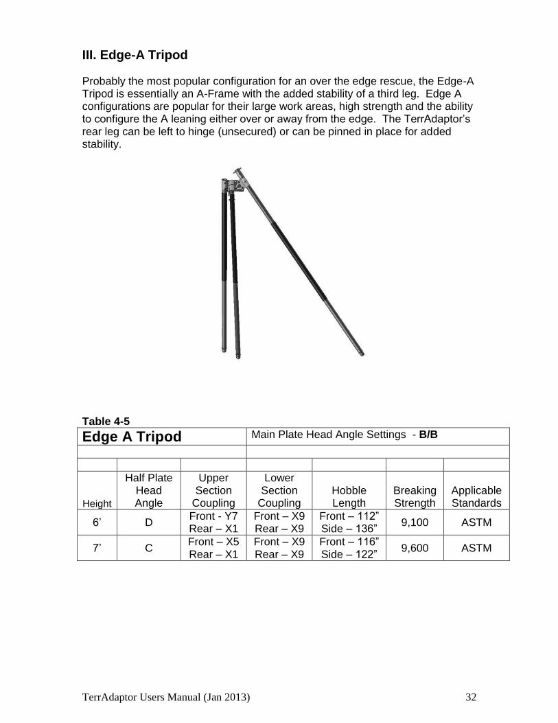
III. Edge-A Tripod
Probably the most popular configuration for an over the edge rescue, the Edge-A Tripod is essentially an A-Frame with the added stability of a third leg. Edge A configurations are popular for their large work areas, high strength and the ability to configure the A leaning either over or away from the edge. The TerrAdaptor’s rear leg can be left to hinge (unsecured) or can be pinned in place for added stability. Table 4-5
Edge A Tripod Main Plate Head Angle Settings - B/B
Height
Half Plate Head Angle
Upper Section
Coupling
Lower Section
Coupling Hobble Length
Breaking Strength
Applicable Standards
6’ D Front - Y7 Rear – X1
Front – X9 Rear – X9
Front – 112” Side – 136”
9,100 ASTM
7’ C Front – X5 Rear – X1
Front – X9 Rear – X9
Front – 116” Side – 122”
9,600 ASTM
Fig 6 6
TerrAdaptor Users Manual (Jan 2013) 33
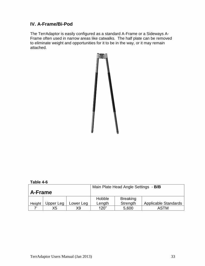
IV. A-Frame/Bi-Pod
The TerrAdaptor is easily configured as a standard A-Frame or a Sideways A-Frame often used in narrow areas like catwalks. The half plate can be removed to eliminate weight and opportunities for it to be in the way, or it may remain attached. Table 4-6
A-Frame
Main Plate Head Angle Settings - B/B
Height Upper Leg Lower Leg Hobble Length
Breaking Strength Applicable Standards
7’ X5 X9 120” 5,600 ASTM
TerrAdaptor Users Manual (Jan 2013) 34
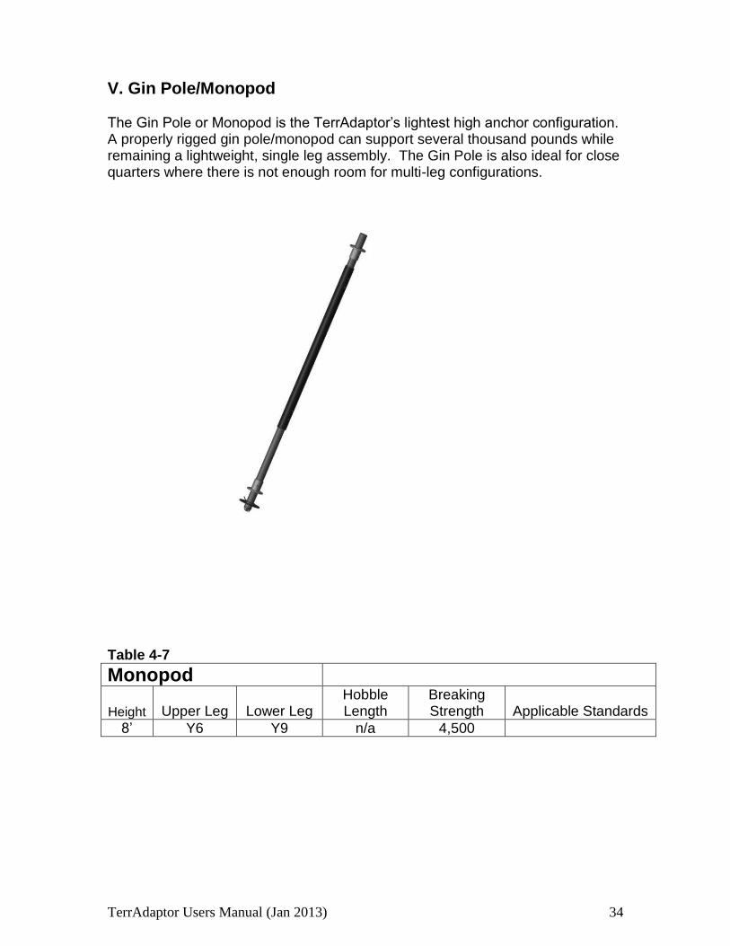
V. Gin Pole/Monopod
The Gin Pole or Monopod is the TerrAdaptor’s lightest high anchor configuration. A properly rigged gin pole/monopod can support several thousand pounds while remaining a lightweight, single leg assembly. The Gin Pole is also ideal for close quarters where there is not enough room for multi-leg configurations.
Table 4-7
Monopod
Height Upper Leg Lower Leg Hobble Length
Breaking Strength Applicable Standards
8’ Y6 Y9 n/a 4,500
TerrAdaptor Users Manual (Jan 2013) 35
VI. Horizontal Span
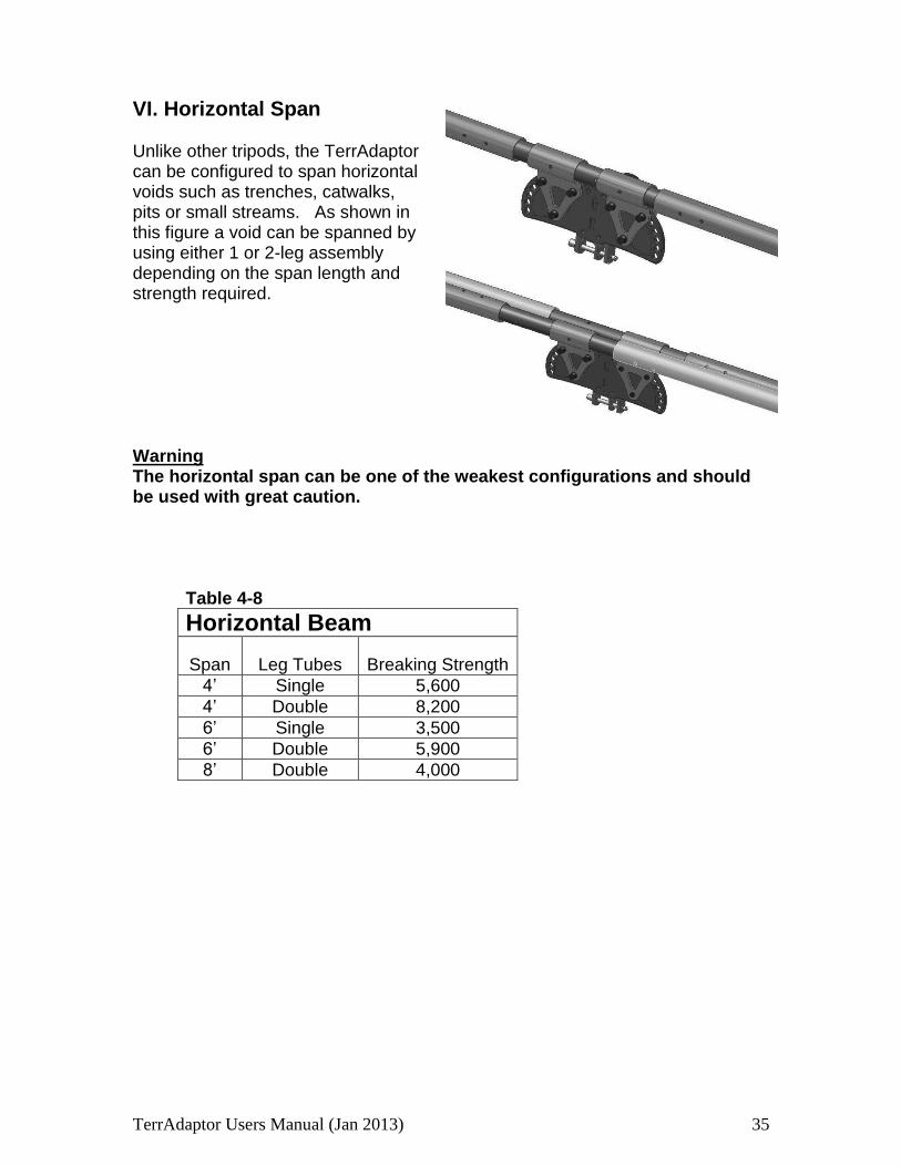
Unlike other tripods, the TerrAdaptor can be configured to span horizontal voids such as trenches, catwalks, pits or small streams. As shown in this figure a void can be spanned by using either 1 or 2-leg assembly depending on the span length and strength required. Warning The horizontal span can be one of the weakest configurations and should be used with great caution.
Table 4-8
Horizontal Beam
Span Leg Tubes Breaking Strength
4’ Single 5,600
4’ Double 8,200
6’ Single 3,500
6’ Double 5,900
8’ Double 4,000
Fig 6 7
TerrAdaptor Users Manual (Jan 2013) 36
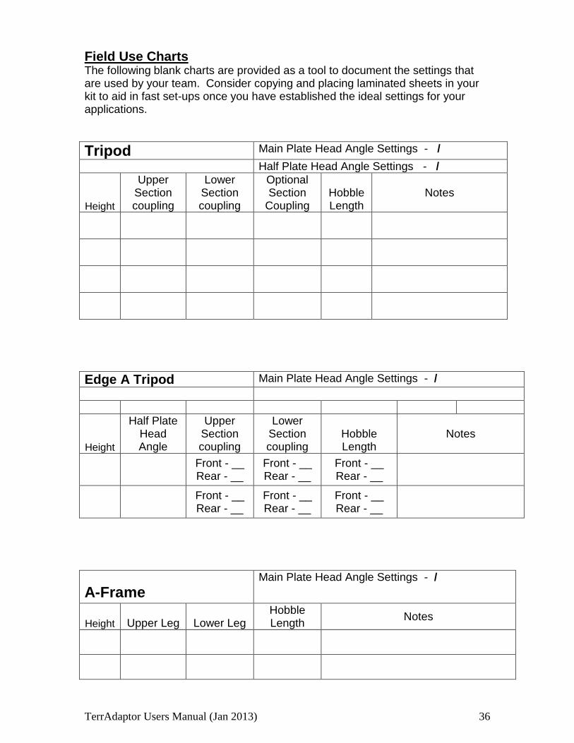
Field Use Charts The following blank charts are provided as a tool to document the settings that are used by your team. Consider copying and placing laminated sheets in your kit to aid in fast set-ups once you have established the ideal settings for your applications.
Tripod Main Plate Head Angle Settings - /
Half Plate Head Angle Settings - /
Height
Upper Section coupling
Lower Section coupling
Optional Section
Coupling Hobble Length
Notes
Edge A Tripod Main Plate Head Angle Settings - /
Height
Half Plate Head Angle
Upper Section coupling
Lower Section coupling
Hobble Length
Notes
Front - __ Rear - __
Front - __ Rear - __
Front - __ Rear - __
Front - __ Rear - __
Front - __ Rear - __
Front - __ Rear - __
A-Frame
Main Plate Head Angle Settings - /
Height Upper Leg Lower Leg Hobble Length
Notes

TerrAdaptor Users Manual (Jan 2013) 37
Symmetric Quadpod Main Plate Head Angle Settings - /
Half Plate Head Angle Settings - /
Height
Upper Section coupling
Lower Section coupling
Optional Lower Leg
Hobble Length
Notes
Inspection & Maintenance Log
Date Inspector (routine
maintenance completed by)
Corrective Repairs and Maintenance performed, if any
TerrAdaptor Users Manual (Jan 2013) 38
Section 5
Warranty and Replacement Parts
Warranty Standard SMC warranty policy applies to the TerrAdaptor System and its component parts: LIMITED WARRANTY: SMC products are warranted to the original purchaser in
accordance with the full Statement of Limited Warranty printed on our web site, www.smcgear.net/warranty. Service under this warranty is available by contacting us by mail, email or phone. All items that are claimed to be defective must be returned under a pre-assigned CC Number and should include a detailed description of the conditions existing during use of the item as well as the place and date of the original purchase and a copy of the original invoice or receipt. Include contact information.
Due to the complexity of the TerrAdaptor system, if one of the main components of the system has been damaged whereby it is warped, twisted, or bent, the entire system is suspect and must be inspected by the manufacturer. As a result, replacement parts for these components are not available without first sending them to SMC for inspection. If during inspection the parts are determined to be damaged as a result of a manufacturer defect, the necessary part(s) will be replaced at no cost to the end user. If the manufacturer determines that the damage is due to miss-use, overloaded, unsafe configurations or neglect, the replacement part(s) will be made available to the user at user’s cost. Any parts deemed unsafe will not be returned to the user.
Replacement Parts and Kit components: NFPA230100 TerrAdaptor™ Tripod System
TerrAdaptor™ Tripod Head
2 Offset Leg Clamps with 3 Load Locking Pins each
Center Leg Clamp with 3 Load Locking Pins
Main Attachment Pin
3 Legs Kits complete with Feet, Hobble Plates & Baskets
3 Rope Hobble Sections
Cotter Pin Kit
1 Extra Leg Coupling Pin and Load Locking Pin
2 Lash Rings with 1 Coupling Pin each
TerrAdaptor™ Head/ Accessory Bag
2 TerrAdaptor™ Leg Bags
TerrAdaptor™ User Guide
230105 TerrAdaptor™ Quadpod Attachment Kit
Quadpod Head Attachment
Leg kit complete with Foot, Hobble Plate & Basket
Center Leg Clamp with 3 Load Locking Pins each
Main Attachment Pin
Rope Hobble Section
TerrAdaptor Users Manual (Jan 2013) 39
230106 TerrAdaptor™ Gin Pole Kit
2 Lash Rings with 1 Coupling Pin each
Leg kit complete with Foot, Hobble Plate & Basket
TerrAdaptor™ User Guide
230217 Foot Replacement Kit
Ball Foot
Hobble Plate with Quick Link
Basket
Leg Coupling Pin
230230 Lash Ring Assembly
1 Lash Ring 1 Leg Coupling Pin 230370 QuickLash Assembly
1 QuickLash 1 Quick Release Pin
230326 Bolt Replacement Kit
4 SHCS Alloy Bolts 4 Nylok Nuts 230107 Leg Extension Kit 1 Mid-Tube 1 Leg Coupling Pin 230260 Load Locking Head Pin
230311 Main Attachment Pin
230301 Leg Coupling Pin 230307 Rope Hobble Section
230314 TerrAdaptor™ Leg Bag
230315 TerrAdaptor™ Head Bag 230360 TerrAdaptor™ Cable Sheave 230500 TerrAdaptor™ Rocker Foot 230510 TerrAdaptor™ Talon Foot 230530 TerrAdaptor™ Articulating Foot 230540 TerrAdaptor™ Modular Adaptor Foot 230550 Standard Winch Bracket 230551 Capstan Winch Bracket 230552 Capstan Winch System


![HDA Design anchor - Motek AS€¦ · Anchor bolt Nominal tensile strength f uk [N/mm²] 800 800 800 ... HDA Design anchor 09 / 2012 77 Anchor TE 24 a) TE 25 a) Anchor Anchor. HDA](https://img.pdfslide.net/doc/110x75/5b34310d7f8b9a436d8bbdfd/hda-design-anchor-motek-as-anchor-bolt-nominal-tensile-strength-f-uk-nmm.jpg)