Embed Size (px)
Citation preview

newport-scientific.com P 301-498-6700 F 301-490-2313 email [email protected] [email protected]
Newport Scientific, Inc 8246E Sandy Court Jessup, MD 20785-9632
USA
Portable Dew Point Monitor
Model 8072A

8072A_A.docx 1 August 2015
Contents
Specifications ............................................................................... 2
Product Overview ........................................................................ 3
Operation .................................................................................... 5
Sample Tubing Connection ...................................................... 5
Power Connection ................................................................... 6
Dryer Performance Testing ..................................................... 7
Material Dryness Testing ......................................................... 7
Remote Monitoring/Data Logging ........................................... 9
Maintenance and Adjustments ................................................. 10
Monitor Disassembly and Assembly ..................................... 10
Sensor Replacement .............................................................. 11
Display Units & Alarm Set Point Adjust ................................. 12
Troubleshooting ........................................................................ 14
Dry-Down Test ....................................................................... 14
Troubleshooting Hints ........................................................... 15
Spare Parts & Accessories ......................................................... 17
Warranty .................................................................................... 19

8072A_A.docx 2 August 2015
Specifications
DEW POINT RANGE -40F to +15F (-40C to -9C) TYPICAL ACCURACY ±3F (±1.7C) ALARM SET POINT -10F (-23C) SENSOR PART NUMBER 1205DM ANALOG OUTPUT SCALING -40F to +70F (-40C to -9C) ANALOG OUTPUT PORT 3 pin M8 male jack POWER REQUIREMENTS 115VAC 50/60HZ
0.15A max (230VAC optional)
DIMENSIONS 10.75” X 9.75” X 4.75” NET WEIGHT 7.0lbs

8072A_A.docx 3 August 2015
Product Overview
The 8072A dew point monitor is used to check the function of a
desiccant dryer or to confirm the dryness of plastic resin in a
hopper. The monitor has a built-in vacuum pump which draws
sample air to be measured and provides real-time indication of
dew point on an LED display. Visual and audible alarm
indicators warn when high dew points are detected.
The dew point monitor and its accessories are housed in a
portable carrying case. Before using the monitor, familiarize
yourself with the features shown below:

8072A_A.docx 4 August 2015
POWER SWITCH Turns monitor ON and OFF.
ALARM SWITCH Enables local audible alarm when dew point exceeds the alarm set point.
LINE CORD Provides connection to power.
BEEPER (not shown)
Gives audible signal when the measured dew point is above the alarm set point.
DEW POINT CONDITION INDICATORS
Green light is on when dry air is detected, red light is on when measured dew point is above the alarm set point.
SAMPLE TUBING Six feet of heat resistant tubing draws in process air to be measured.
AIR FILTER Installed in-line with sample tubing, removes fine particulates from sample air.
DESICCANT TUBE Provides dry air for testing the monitor’s response.
TUBING STORAGE BRACKET
Allows storage for sample tubing and desiccant tube when not in use.
ANALOG OUT 4-20mA and 0-5V output for remote monitoring or data logging. Mates with standard 3 pin M8 female cable.
NOTE: The 8072A is shipped with a paper desiccant pack
which can be discarded when the unit is unpacked.

8072A_A.docx 5 August 2015
Operation
The 8072A is designed to sample process air that is near
atmospheric pressure, NOT compressed air. If you are
attempting to monitor compressed air, consult the factory for
other model options.
NOTE: For best sensor life and response time, avoid sampling
ambient air of high humidity. Leave unit off when not
monitoring a dryer or hopper.
CAUTION: The carrying case is not heat resistant. It may melt
or distort if left resting on the hot parts of a heated dryer. If a
surface is too hot to touch, it is too hot for the 8072A!
Sample Tubing Connection
To enable testing of your process air, you must provide fittings
in your drying system that will accept the 8072A’s 3/16” ID
sample tubing. This can be a barbed hose fitting or a piece of
¼” copper tube that penetrates your dryer’s air hoses. The
point of attachment must be secure and leak-free.
The plastic sample tubing supplied with the monitor can
tolerate temperatures up to 275F (135C). Higher process air
temperatures can be cooled to a safe level by sampling through
a few feet of ¼” copper tubing.
Select the sample locations based on your testing needs (refer
to diagram below). It is suggested that you have permanently
accessible sample points at both the dryer output and return
hoses. If your dryer has threaded test ports on the inlet and
outlet connections (typically for thermocouples) use these to

8072A_A.docx 6 August 2015
make points of connection. Some dryer manufacturers provide
a port for sampling.
NOTE: When storing the 8072A, carefully coil the sample
tubing and tuck it behind the tubing storage bracket. This will
prevent kinks from forming in the tubing when the lid is
closed.
Power Connection
The 8072A is supplied with a 6 foot line cord for connection to
power. Always connect the monitor to the correct supply
voltage. Do not attempt to replace the line cord with a different
plug type to accommodate other supply voltages. The 8072A
will be damaged if connected to incorrect supply voltage.
Dryer testing sample location
Material testing sample location
Dryer
Hopper Air flow

8072A_A.docx 7 August 2015
Dryer Performance Testing
The performance of a dryer can be evaluated by measuring the
dew point of its output air.
Connect the 8072A sample tubing to a point on the dryer’s
output line, before the hopper. Make sure not to exceed the
sample tubing temperature rating.
Turn on the 8072A and allow the reading to stabilize. The initial
reading will be +15F (-9C) until all the ambient air is purged from the monitor’s tubing and internal fittings. After a few minutes, the reading should start to drop until a stable reading is obtained. It can take 30 minutes or more for the unit to stabilize when first turned on.
NOTE: Not all dryers produce a -40F dew point. Check with
your dryer manufacturer for expected dew point levels.
Leave the 8072A connected and turned on during material drying and processing. The built in red light and audible beeper will indicate dryer trouble within moments of a dew point rise. A constantly high reading on the 8072A may indicate a
malfunctioning dryer or one that is overloaded by damp
material in the hopper. If you suspect that the 8072A is giving
an incorrect high reading, perform the Dry-Down Test described
in the Troubleshooting section of this manual.
Material Dryness Testing
The dryness of material in a hopper can be inferred from the
dew point of air exiting the hopper.
Connect the 8072A sample tubing to a point in the hopper’s air

8072A_A.docx 8 August 2015
output. Make sure not to exceed the sample tubing temperature rating. Turn on the 8072A. When a hopper is initially loaded with material, high dew points at the hopper’s air return are normal
while moisture is removed. The initial reading will be +15F (-
9C) and will stay at that reading until the material begins to dry. It can take many hours to dry some materials. If drying time is expected to be all day, leave the 8072A sample tubing connected, but keep the monitor turned off. Every few hours, turn on the 8072A and allow at least 30 minutes for a reading. As the material dries, the 8072A dew point reading will start to drop. Material processing can begin when the dew point reading is at an acceptable level.
If the 8072A reading is stuck at +15F (-9C), change the sampling point to the output of the dryer. Follow the instructions for Dryer Performance Testing described above to make sure the dryer is providing low dew point air to the hopper.

8072A_A.docx 9 August 2015
Remote Monitoring/Data Logging
The 8072A analog output jack can be used to monitor or log
dew point over a period of time.
The output jack is a 3 pin male M8 type connector. This
connector accepts standard threaded or snap fit female M8
cables.
PIN 1 0-5V signal PIN 3 Ground PIN 4 4-20mA self-powered signal (current sourcing)
Note that the output scaling is -40F to +70F.

8072A_A.docx 10 August 2015
Maintenance and Adjustments
Newport Scientific offers a maintenance and calibration service
for the 8072A. This service should be performed annually.
Alternatively, most wearable parts can be replaced by the user.
To access the serviceable parts inside the monitor, the 8072A
panel must be removed from the carrying case.
Monitor Disassembly and Assembly
WARNING: Unplug the 8072A from power before disassembly.
Even with the power switch off, voltages are present inside the
unit.
Slide the sample tubing off of the front panel elbow.
Use a screwdriver to remove the 5 screws along the perimeter
of the panel holding it in the case. Use the sample tubing elbow
to help lift the panel straight up and out of the case.
When re-assembling the panel into the case, make sure sensor
cable wires are tucked in and not pinched under the panel as
you lower it into the case.
Install the 5 mounting screws, taking care not to cross thread
the screws as you proceed. The screws only need to be snug to
the panel, do not overtighten!

8072A_A.docx 11 August 2015
Sensor Replacement
The internal sensor should be replaced on a yearly basis. It is
difficult to verify the accuracy of the sensor in the field. For
most users, an annual sensor
replacement can assure good
operation of the monitor. It is
recommended to replace the
sample tubing and air filter
whenever the sensor is replaced.
With the panel removed from
the case, locate the sensor
housing and pull the sensor
cable connector from the
housing. The cable will unplug
straight out.
Unscrew the hex nut from the top of the sensor housing. With
the hex nut unscrewed, remove the sensor and insert along
with gasket. The sensor
will then unplug from the
insert. Replace sensor
and inspect gasket for
damage. Reassemble all
parts, hand tighten the
hex nut, and plug in the
cable connector.

8072A_A.docx 12 August 2015
Display Units & Alarm Set Point Adjust
The 8072A is factory set to
display dew point in F. The
display can be changed to
C by jumper configuration.
With the 8072A panel
removed from the carrying
case, locate the
configurable parts near the
upper left corner of the PC
board. Move J6 and J7
jumpers to the C position to
display dew point in C.
To change the dew point at which the monitor indicates an
alarm (high dew point indication), use the DISPLAY MODE
SWITCH labeled S1 and the ALARM ADJUST potentiometer
labeled SET1.
WARNING: The alarm set point adjustment is performed with
the 8072A powered on. Avoid touching live electrical parts
during this procedure as hazardous voltages are present!

8072A_A.docx 13 August 2015
OP
ER
SET1
SET2
S1
Apply power to the unit and turn it on with care, making sure
not to touch any electrical terminals inside.
Configure the S1 switch as shown here, with
SET1 position ON and all others OFF. In this
configuration, the front panel display will
indicate the current alarm set point. Adjust the
SET1 potentiometer to the desired set point.
When the front panel display indicates your
desired set point, return the S1 switches to the
normal operating configuration. The front
panel display will now show the actual
measured dew point (note that most ambient
air will cause the monitor to read +15F).
Remove power and reinstall the 8072 panel into the carrying
case.
OP
ER
SET1
SET2
S1

8072A_A.docx 14 August 2015
Troubleshooting
Dry-Down Test
The desiccant tube is used to provide a reliable source of dry air
for field testing the monitor’s response. Follow this procedure
if the monitor indicates a constant high dew point but you
suspect that your process air is dry.
NOTE: Make sure the desiccant is blue in color. If the
desiccant is fully pink, it will not produce dry air and you
should purchase a new desiccant tube before testing.
Remove the yellow caps from the ends of the desiccant tube-
save them for re-use. Connect the sample tubing to one end of
the desiccant tube, and the sample air outlet to the other end.
This will create a closed loop of dry air flow through the monitor
and desiccant
tube. Turn on the
dew point
monitor. In a few
minutes, the
reading should
start to drop
from +15F (-
9C). Allow up to
an hour for a -40
reading. If the monitor doesn’t respond, refer to the
troubleshooting hints for more information. Replace the
desiccant tube caps when done.

8072A_A.docx 15 August 2015
Troubleshooting Hints
Monitor display is stuck at +15F (-9C)
Possible Cause Corrective Action
Room air getting into monitor
Make sure the fitting at your sample point is air tight. Also, check for a cracked air filter and replace if needed.
Inadequate sampling suction With monitor on, use finger to block sample tubing. If you don’t feel suction, the vacuum pump may be worn or damaged, or the 2 pin insert holding the sensor may be cracked and leaking. Monitor should be serviced.
Sensor worn or contaminated
Using a fresh desiccant tube, perform the Dry Down test. If response is slow, replace sensor.
Sampled air is not dry Sampled air must have a dew
point of +15F or lower for monitor to respond. Check the Operation section for proper use of the monitor.

8072A_A.docx 16 August 2015
Monitor reads -40 when turned on and doesn’t change
Possible Cause Corrective Action
Sensor cable disconnected Disassemble the monitor and make sure sensor cable is plugged into the 2 pin insert.
Sensor broken or missing Unplug the sensor cable and short the cable pins together with a jumper wire. Turn
monitor on and check for +15F on display. If so, the sensor needs replaced.
Circuit board defective. Unplug the sensor cable and short the cable pins together with a jumper wire. Turn
monitor on and check for +15F on display. If display stays at -
40, the monitor needs factory service.
8072A_A.docx 17 August 2015
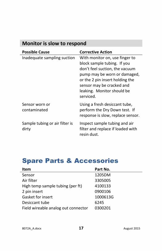
Monitor is slow to respond
Possible Cause Corrective Action
Inadequate sampling suction With monitor on, use finger to block sample tubing. If you don’t feel suction, the vacuum pump may be worn or damaged, or the 2 pin insert holding the sensor may be cracked and leaking. Monitor should be serviced.
Sensor worn or contaminated
Using a fresh desiccant tube, perform the Dry Down test. If response is slow, replace sensor.
Sample tubing or air filter is dirty
Inspect sample tubing and air filter and replace if loaded with resin dust.
Spare Parts & Accessories
Item Part No.
Sensor 1205DM Air filter 3305005 High temp sample tubing (per ft) 4100133 2 pin insert 0900106 Gasket for insert 1000613G Desiccant tube 6245 Field wireable analog out connector 0300201

8072A_A.docx 18 August 2015

8072A_A.docx 19 August 2015
Warranty
NEWPORT SCIENTIFIC, INC. warrants that all equipment manufactured by NSI shall be free from defects in material and workmanship which might impair its usefulness. SELLER DOES NOT WARRANT THAT THE EQUIPMENT IS FIT FOR ANY PARTICULAR USE. THERE ARE NO WARRANTIES WHICH EXTEND BEYOND THE DESCRIPTION ON THE FACE HEREOF; the obligation under this warranty is limited to repairing or replacing, at Seller's factory, any defective parts which, when returned by the buyer, TRANSPORTATION PREPAID, examination discloses to have been factory defective. The time limit of this warranty is ONE YEAR from date of shipment of new equipment, SIX MONTHS from date of shipment of Hygrodynamics Wide-Range Sensors and THREE MONTHS from date of shipment of Hygrodynamics Narrow-Range Sensors and repaired equipment. THIS WARRANTY IS EXPRESSLY IN LIEU OF OTHER WARRANTIES. Seller shall not be held liable for any special, indirect, consequential damages arising out of this warranty or any breach thereof, of any defect in or failure or malfunction of the equipment and materials are further subject to tolerances and variations consistent with usages of trade. This warranty shall run in favor only of the purchaser from Seller and may not be passed on or represented on behalf of Seller to any subsequent purchaser.
WARRANTIES: OTHER PRODUCTS NEWPORT SCIENTIFIC, INC. makes no express or implied warranty as to items, which are the products of other manufacturers. Seller shall use its best efforts to obtain from the manufacturer, in accordance with its customary practice, the repair or replacement of such products may prove defective in workmanship or material. The foregoing states the entire liability in respect to such products, except as an authorized executive of the corporation may otherwise agree in writing. In the case of special equipment or modifications to standard equipment manufactured at the request of the buyer, under buyer-approved specifications, buyer will indemnify Seller against the risk damages due to patent infringement.

newport-scientific.com P 301-498-6700 F 301-490-2313 email [email protected] [email protected]
Newport Scientific, Inc 8246E Sandy Court Jessup, MD 20785-9632
USA