Embed Size (px)
Citation preview

IMPORTANT: Read and understand this manual before assembling, starting or servicingheater. Improper use of heater can cause serious injury. Keep this manual for future reference.
Heater Sizes: 40,000 55,000 60,000 70,000 110,000 115,000150,000 155,000 165,000 and 200,000 Btu/Hr Models
H.S.I. Series
PORTABLE FORCEDAIR HEATERSOWNER’S MANUAL
TABLE OF CONTENTS
SAFETY INFORMATION ............................................................ 2
PRODUCT IDENTIFICATION ..................................................... 3
UNPACKING ............................................................................... 3
THEORY OF OPERATION ......................................................... 4
FUELS......................................................................................... 4
VENTILATION ............................................................................. 4
ASSEMBLY ................................................................................. 5
OPERATION ............................................................................... 5
OPERATION WITH PORTABLE GENERATOR .......................... 6
PREVENTATIVE MAINTENANCE SCHEDULE ......................... 6
STORING, TRANSPORTING, OR SHIPPING ............................ 6
TROUBLESHOOTING ................................................................ 7
SERVICE PROCEDURES .......................................................... 8
TECHNICAL SERVICE ............................................................. 15
REPLACEMENT PARTS .......................................................... 15
SPECIFICATIONS .................................................................... 16
WIRING DIAGRAMS................................................................. 16
ILLUSTRATED PARTS BREAKDOWN AND PARTS LIST ....... 18
WHEELS AND HANDLES ........................................................ 24
ACCESSORIES ........................................................................ 25
WARRANTY AND REPAIR SERVICE ...................................... 26
®
Save this manual for future reference.Save this manual for future reference.
For more information, visit www.desatech.comFor more information, visit www.desatech.com
Fill In For Your Records
Model No. ___________________(Located on side panel)
Serial No. ___________________(Located on fuel tank)
Date of Purchase: ______________
TM

108871
2
For more information, visit www.desatech.comFor more information, visit www.desatech.com
SAFETY INFORMATION
WARNINGS
IMPORTANT: Read this owner’s manual carefully andcompletely before trying to assemble, operate, or ser-vice this heater. Improper use of this heater can causeserious injury or death from burns, fire, explosion,electrical shock, and carbon monoxide poisoning.
DANGER: Carbon monoxide poisoning may leadto death!
Carbon Monoxide Poisoning: Early signs of carbon monoxidepoisoning resemble the flu, with headaches, dizziness, and/or nau-sea. If you have these signs, the heater may not be working properly.Get fresh air at once! Have heater serviced. Some people are moreaffected by carbon monoxide than others. These include pregnantwomen, persons with heart or lung disease or anemia, those underthe influence of alcohol, and those at high altitudes.
Make certain you read and understand all warnings. Keep thismanual for reference. It is your guide to safe and proper operationof this heater.
• Use only kerosene, #1#2 diesel/fuel oil, JET A or JP-8 fuels toavoid risk of fire or explosion. Never use gasoline, naphtha,paint thinners, alcohol, or other highly flammable fuels.
• Fuelinga)Personnel involved with fueling shall be qualified and thor-
oughly familiar with the manufacturer's instructions and ap-plicable regulations regarding the safe fueling of heating units.
b)Only the type of fuel specified on the heater's data plate shallbe used.
c)All flame, including the pilot light, if any, shall be extin-guished and the heater allowed to cool, prior to fueling.
d)During fueling, all fuel lines and fuel-line connections shallbe inspected for leaks. Any leaks shall be repaired prior toreturning the heater to service.
e)At no time shall more than one day's supply of heater fuelbe stored inside a building in the vicinity of the heater. Bulkfuel storage shall be outside the structure.
f) All fuel storage shall be located a minimum of 762cm (25feet) from heaters, torches, welding equipment, and similarsources of ignition (exception: the fuel reservoir integral withthe heater unit).
g)Whenever possible, fuel storage shall be confined to areaswhere floor penetrations do not permit fuel to drip onto orbe ignited by a fire at lower elevation.
h)Fuel storage shall be in accordance with the authority hav-ing jurisdiction.
• Use only the electrical voltage and frequency specified onmodel plate.
• Heater must be grounded. Use only a properly grounded three-wire extension cord. Plug into grounded outlet only.
• Use only in areas free of flammable vapors or high dust content.
• Minimum clearance from any combustible materials: 8 feet(244 cm) from hot air outlet; 6 feet (183 cm) from top; and 2feet (61 cm) from sides and inlet.
• Locate heater on a stable and level surface while hot or operat-ing or a fire may occur.
• Use only in well-vented areas. Before using heater, provide atleast a 2800 square cm (three-square-foot) opening of fresh,outside air for each 30 kw (100,000 Btu/Hr) of rating. Thisheater produces carbon monoxide, which is listed by the Stateof California as a reproductive toxin under Proposition 65.
• Keep children and animals away from heater at all times.
• Never start heater when combustion chamber is hot or if fuelhas accumulated in combustion chamber.
• When used with thermostat, heater may start at anytime.
• When heater is moved or stored, it must be in a level positionor fuel spillage may occur.
• Use heater only in accordance with local ordinances and codes.
• Never use gasoline, crankcase drainings, naphtha, paintthinners, alcohol, or other highly flammable fuels.
• Never use heater where gasoline, paint thinner, or other highlyflammable vapors are present.
• Never use heater in living or sleeping areas.
• Never leave a heater plugged in without adult supervision ifchildren or animals are likely to be present.
• Never move, handle, refuel, or service a hot, operating, orplugged-in heater.
• Never attach duct work to front or rear of heater.
• Never attach heater to external fuel tank.
• Heaters used in the vicinity of tarpaulins, canvas, or similarenclosure materials shall be located a safe distance from suchmaterials. The recommended minimum safe distance is304.8cm (10 feet). It is further recommended that these enclo-sure materials be of a fire retardant nature. These enclosurematerials shall be securely fastened to prevent them from ig-niting or from upsetting the heater due to wind action.
• Unplug heater when not in use.
• Never block air inlet (rear) or air outlet (front) of heater.
• Warning to New York City ResidentsFor Use Only At Construction Sites in accordance with ap-plicable NYC codes under NYCFD certificate of approval#4803, #4899, #4908, #4909, or #4934.
SAFETY INFORMATION
108871
33
For more information, visit www.desatech.comFor more information, visit www.desatech.com
Side Cover
LowerShell
FuelCap
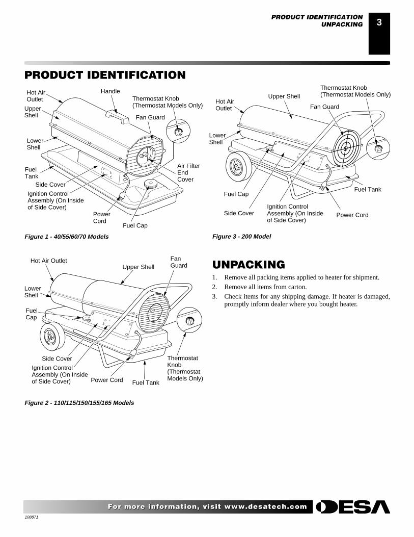
Hot Air OutletUpper Shell
Power Cord Fuel Tank
FanGuard
LowerShell
Side Cover
FuelTank
UpperShell
Hot AirOutlet
Handle
Fan Guard
Air FilterEndCover
Fuel Cap
PowerCord
Ignition ControlAssembly (On Insideof Side Cover)
Ignition ControlAssembly (On Insideof Side Cover)
PRODUCT IDENTIFICATION
Figure 1 - 40/55/60/70 Models
Figure 2 - 110/115/150/155/165 Models
UNPACKING1. Remove all packing items applied to heater for shipment.
2. Remove all items from carton.
3. Check items for any shipping damage. If heater is damaged,promptly inform dealer where you bought heater.
PRODUCT IDENTIFICATIONUNPACKING
Thermostat Knob(Thermostat Models Only)
ThermostatKnob(ThermostatModels Only)
Figure 3 - 200 Model
LowerShell
Hot AirOutlet
Side Cover
Fuel Cap
Upper Shell
Power CordIgnition ControlAssembly (On Insideof Side Cover)
Fan Guard
Fuel Tank
Thermostat Knob(Thermostat Models Only)

108871
4
For more information, visit www.desatech.comFor more information, visit www.desatech.com
Figure 4 - Cross Section Operational View
THEORY OF OPERATIONFUELSVENTILATION
THEORY OF OPERATIONThe Fuel System: The air pump forces air through the air line. The airis then pushed through the nozzle. This air causes fuel to be lifted fromthe tank. A fine mist of fuel is sprayed into the combustion chamber.
The Air System: The motor turns the fan. The fan pushes air intoand around the combustion chamber. This air is heated and providesa stream of clean, hot air.
The Ignition System: The ignition control assembly providespower to the ignitor. This ignites the fuel/air mixture in the combus-tion chamber.
The Flame-Out Control System: This system causes the heater toshut down if the flame goes out.
VENTILATION
WARNING: Provide a fresh air opening of at leastthree square feet (2,800 square cm) for each 100,000BTU/HR rating. Provide extra fresh air if more heatersare being used. The minimum ventilation require-ments must be followed to avoid risks associatedwith carbon monoxide poisoning. Make certain theserequirements are met prior to operating heater.
Example: A 58.6kw (200,000 Btu/Hr) heater requires one of thefollowing:
• a two-car garage door [4.88 meter (16 feet) opening] raised12.7 cm (5 inches)
• a single-car garage door [2.74 meter (9 feet) opening] raised20.3 cm (8 inches)
• two, 76.2 cm (30 inch) windows raised 38.1 cm (15 inches)
CleanHeatedAir Out
FuelFilter
Air LineTo Burner
AirOutputFilter
Air PumpAir IntakeFilter
CoolAirIn
Fan
Combustion ChamberIgnitor
Motor
Ignition ControlAssembly
Air For Fuel SystemAir For CombustionAnd Heating Fuel
NozzleFuelTank
FUELS
Use only kerosene, #1/#2 diesel/fuel oil, JET A or JP-8 fuels.Heavier fuels such as No. 2 fuel oil or No. 2 diesel fuel may also beused but will result in:
• noticeable odor
• additional fuel filter maintenance
• the need for nontoxic, anti-icer additives in very cold weather
Do not use fuels heavier than No. 2 grade or heavy oils such as oildrained from crankcases. These heavy oils will not ignite properlyand will contaminate the heater.
IMPORTANT: Use a KEROSENE ONLY (blue) or DIESEL ONLY(yellow) storage container. Be sure storage container is clean. For-eign matter such as rust, dirt, or water will cause the ignition controlassembly to shut down heater. Foreign matter may also requireheater's fuel system to be frequently cleaned.
WARNING: Use only kerosene, #1/#2 diesel/fueloil, JET A or JP-8 fuels to avoid risk of fire or explo-sion. Never use gasoline, oil drained from crank-cases, naphtha, paint thinners, alcohol or other highlyflammable fuels.

108871
55
For more information, visit www.desatech.comFor more information, visit www.desatech.com
Figure 5 - Wheel and Handle Assembly, 110/115/150/155/165/200 Models Only
WheelSupportFrame
Fuel TankFlange
Cap Nut
Wheel
Nut
Axle
ExtendedHub
AirInlet
Handle
Hot AirOutlet
Screw
ASSEMBLY(FOR 110/115/150/155/165/200 MODELSONLY)These models are furnished with wheels and a rear handle. Somemodels are furnished with a front handle also. Wheels, handle(s),and the mounting hardware are found in the shipping carton.
Tools Needed• Medium Phillips Screwdriver
• 3/8" Open or Adjustable Wrench
• Hammer
1. Slide axle through wheel support frame. Install wheels on axle.
IMPORTANT: When installing wheels, point extended hub ofwheels toward wheel support frame (see Figure 5).
2. Place cap nuts on axle ends. Gently tap with hammer to secure.
3. Place heater on wheel support frame. Make sure hot air outletend (front) of heater is over wheels. Line up holes on fuel tankflange with holes on wheel support frame.
4. Place rear handle (and front handle if provided) on top of fueltank flange. Insert screws through handle(s), fuel tank flange,and wheel support frame. Attach nut finger tight after eachscrew is inserted.
5. After all screws are inserted, tighten nuts firmly.
ASSEMBLYOPERATION
Front Handle(If Provided)
TO START HEATER1. Follow all ventilation and safety information.
2. Locate heater to provide maximum circulation of the heatedair. Follow all location requirements noted in Safety Informa-tion, page 2.
3. Fill fuel tank with kerosene, #1#2 diesel/fuel oil, JET A orJP-8 fuel.
4. Attach fuel cap.
5. For thermostat models, turn thermostat knob clockwise to thehigh position.
6. Plug heater’s power cord into approved, grounded, three-wireextension cord. Extension cord must be at least six feet (1.8meters) long.
Extension Cord Size Requirement6 to 10 feet (1.8 to 3 meters) long, use 18 AWG (0.75 mm2)rated cord
11 to 100 feet (3.3 to 30.5 meters) long, use 16 AWG (1.0 mm2)rated cord
101 to 200 feet (30.8 to 61 meters) long, use 14 AWG (1.5 mm2)rated cord
7. Plug extension cord into standard 120 volt/60 hertz, 3-pronggrounded outlet. Note: Ignitor will preheat for five seconds,then heater will start.
8. For thermostat models, adjust thermostat knob to the desiredsetting. Note: A cold heater may affect the thermostat setting.This thermostat is a general-heating control. It is not intendedfor precise temperature control. Adjust thermostat until heatercycles at the desired setting.
TO STOP HEATERUnplug extension cord from outlet.
TO RESTART HEATER1. Unplug extension cord from outlet and wait 10 seconds. (Wait
two minutes if heater has been running.)
2. Repeat steps under To Start Heater.
OPERATIONIMPORTANT: Review and understand the warningsin the Safety Information section, page 2. They areneeded to safely operate this heater. Follow all localordinances and codes when using this heater.

108871
6
For more information, visit www.desatech.comFor more information, visit www.desatech.com
WARNING: Before operating heater or any appli-ance from a portable generator, verify that generatorhas been properly connected to earth ground. Im-proper grounding or failure to ground generator canresult in electrocution if a ground fault occurs. Referto owner’s manual supplied by generator manufac-turer for proper grounding procedures.
The operating voltage range of the heater is 108 to 132 Volts (120Volts +/- 10%). Prior to plugging heater into generator the outputvoltage should be verified (if generator is equipped with the automaticidle feature, the output voltage should be measured with the generatorrunning at full speed). If the voltage does not measure in this rangethe heater should not be plugged into the generator.
Refer to Operation, page 5, for starting, stopping, and resettingheater procedures.
PREVENTATIVE MAINTENANCE SCHEDULE
How To
See Storing, Transporting, or Shipping, above
See Air Output, Air Intake, and Lint Filters, page 8
See Air Output, Air Intake, and Lint Filters, page 8
See Fuel Filter, pages 9 and 10
See Fan, page 8
WARNING: Never service heater while it is plugged in, operating, or hot. Severe burns and electrical shockcan occur.
Item
Fuel tank
Air output and lint filters
Air intake filter
Fuel filter
Ignitor
Fan blades
Motor
How Often
Flush every 150-200 hours of operation or as needed
Replace every 500 hours of operation or once a year
Wash and dry with soap and water every 500 hoursof operation or as needed
Clean twice a heating season or as needed
No maintenance required
Clean every season or as needed
Not required/permanently lubricated
STORING, TRANSPORTING,OR SHIPPINGNote: If shipping, transport companies require fuel tanks to be empty.
1. Drain fuel tank.
Note: Some models have drain plug on underside of fuel tank.If so, remove drain plug to drain all fuel. If heater does nothave drain plug, drain fuel through fuel cap opening. Be sureall fuel is removed.
2. Replace drain plug if provided.
3. If any debris is noted in old fuel, add 1 or 2 quarts of cleankerosene to tank, stir, and drain again. This will prevent ex-cess debris from clogging filters during future use.
4. Replace fuel cap or drain plug. Properly dispose of old anddirty fuel. Check with local automotive service stations thatrecycle oil.
5. If storing, store heater in dry place. Make sure storage place isfree of dust and corrosive fumes.
IMPORTANT: Do not store kerosene over summer months for useduring next heating season. Using old fuel could damage heater.
OPERATION WITH PORTABLE GENERATORSTORING, TRANSPORTING, OR SHIPPINGPREVENTATIVE MAINTENANCE SCHEDULE
OPERATION WITH PORTABLEGENERATOR
Figure 6 - Typical Generator Grounding Method (Generatorconstruction may vary from that shown)
Ground Lug
Ground Wire (#10 AWG -Stranded-Copper)
AlternatorCopper or BrassGrounding Point
108871
77
For more information, visit www.desatech.comFor more information, visit www.desatech.com
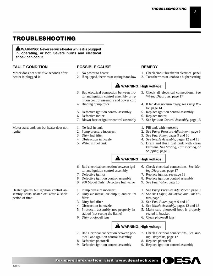
REMEDY
1. Check circuit breaker in electrical panel2. Turn thermostat knob to a higher setting
3. Check all electrical connections. SeeWiring Diagrams, page 17
4. If fan does not turn freely, see Pump Ro-tor, page 14
5. Replace ignition control assembly6. Replace motor7. See Ignition Control Assembly, page 15
1. Fill tank with kerosene2. See Pump Pressure Adjustment, page 93. See Fuel Filter, pages 9 and 104. See Nozzle Assembly, pages 12 and 135. Drain and flush fuel tank with clean
kerosene. See Storing, Transporting, orShipping, page 6
6. Check electrical connections. See Wir-ing Diagrams, page 17
7. Replace ignitor, see page 118. Replace ignition control assembly9. See Fuel Valve, page 10
1. See Pump Pressure Adjustment, page 92. See Air Output, Air Intake, and Lint Fil-
ters, page 83. See Fuel Filter, pages 9 and 104. See Nozzle Assembly, pages 12 and 135. Make sure photocell boot is properly
seated in bracket6. Clean photocell lens
7. Check electrical connections. See Wir-ing Diagrams, page 17
8. Replace photocell9. Replace ignition control assembly
POSSIBLE CAUSE
1. No power to heater2. If equipped, thermostat setting is too low
3. Bad electrical connection between mo-tor and ignition control assembly or ig-nition control assembly and power cord
4. Binding pump rotor
5. Defective ignition control assembly6. Defective motor7. Blown fuse or ignitor control assembly
1. No fuel in tank2. Pump pressure incorrect3. Dirty fuel filter4. Obstruction in nozzle5. Water in fuel tank
6. Bad electrical connection between igni-tor and ignition control assembly
7. Defective ignitor8. Defective ignition control assembly9. 200 Model Only: Defective fuel valve
1. Pump pressure incorrect2. Dirty air intake, air output, and/or lint
filter3. Dirty fuel filter4. Obstruction in nozzle5. Photocell assembly not properly in-
stalled (not seeing the flame)6. Dirty photocell lens
7. Bad electrical connection between pho-tocell and ignition control assembly
8. Defective photocell9. Defective ignition control assembly
WARNING: High voltage!
FAULT CONDITION
Motor does not start five seconds afterheater is plugged in
Motor starts and runs but heater does notignite
Heater ignites but ignition control as-sembly shuts heater off after a shortperiod of time
WARNING: High voltage!
TROUBLESHOOTING
TROUBLESHOOTING
WARNING: Never service heater while it is pluggedin, operating, or hot. Severe burns and electricalshock can occur.
WARNING: High voltage!

108871
8
For more information, visit www.desatech.comFor more information, visit www.desatech.com
SERVICE PROCEDURES
WARNING: To avoid risk of burn and electricalshock, never attempt to service heater while it isplugged in, operating, or hot.
Upper Shell
FanGuard
Figure 7 - Upper ShellRemoval, 40/50/60/70Models Only
Figure 8 - Upper ShellRemoval, 110/115/150/155/165/200 Models Only
FanGuard
Upper Shell
UPPER SHELL REMOVAL1. Remove screws along each side of heater using 5/16" nut-driver.
These screws attach upper and lower shells together. See Fig-ure 7 or 8.
2. Lift upper shell off.
3. Remove fan guard.
ScrewScrew
FANIMPORTANT: Remove fan from motor shaft before removingmotor from heater. The weight of the motor resting on the fan coulddamage the fan pitch (see Figure 9).
1. Remove upper shell (see Figure 7 or 8).
2. Use 1/8" allen wrench to loosen setscrew which holds fan tomotor shaft.
3. Slip fan off motor shaft.
4. Clean fan using a soft cloth moistened with kerosene or solvent.
5. Dry fan thoroughly.
6. Replace fan on motor shaft. Place fan hub flush with end ofmotor shaft (see Figure 10).
7. Place setscrew on flat of shaft. Tighten setscrew firmly (40-50inch-pounds/4.5-5.6 n-m).
8. Replace fan guard and upper shell.
AIR OUTPUT, AIR INTAKE AND LINT FILTERS1. Remove upper shell (see Figure 7 or 8).
2. Remove filter end cover screws using 5/16" nut-driver (seeFigure 11 or 12).
3. Remove filter end cover.
4. Replace air output and lint filters.
5. Wash or replace air intake filter (see Preventative MaintenanceSchedule, page 6).
6. Replace filter end cover.
7. Replace fan guard and upper shell.
IMPORTANT: Do not oil filters.
MotorShaft
Setscrew
Figure 9 - Fan, Motor Shaft,and Setscrew Location
MotorShaft
Fan
Setscrew
Figure 10 - Fan Cross Section
Fan
Flush
Motor
Figure 11 - Air Output, Air Intake, and Lint Filters, 40/55/60/70Models Only
Air IntakeFilter
Lint Filter
Filter EndCover
Air OutputFilter
Figure 12 - Air Output, Air Intake, and Lint Filters, 110/115/150/155/165/200 Models Only
Air IntakeFilter
Filter EndCover
Lint Filter
Air Output Filter
SERVICE PROCEDURES

108871
99
For more information, visit www.desatech.comFor more information, visit www.desatech.com
Figure 15 - Fuel Filter Removal, 40/55/60/70 Models
Fuel Filterand Bushing
Side Cover
Upper Fuel Line
Fuel Filter, Bushing,and Lower Fuel Line
Upper Fuel Line
SideCover
Figure 16 - Fuel Filter Removal, 110/115/150/155/165 Models
SERVICE PROCEDURES
PUMP PRESSURE ADJUSTMENT1. Remove pressure gauge plug from filter end cover (see Figure 13).
2. Install accessory pressure gauge (part number HA1180).
3. Start heater (see Operation, page 5). Allow motor to reachfull speed.
4. Adjust pressure. Turn relief valve to right to increase pressure.Turn relief valve to left to decrease pressure. See specifica-tions correct pressure for each model (see Figure 14).
5. Remove pressure gauge. Replace pressure gauge plug in filterend cover.
SERVICE PROCEDURESContinued
Figure 13 - Pressure Gauge Plug Removal (40/55/60/70 ModelsShown)
PressureGaugePlug
PressureGauge
Figure 14 - Adjusting Pump Pressure (40/55/60/70 Models Shown)
ReliefValve
PumpModel Pressure
40 3.0 PSI55 3.4 PSI60 3.4 PSI70 4.7 PSI
110 5.3 PSI115 5.3 PSI150 5.4 PSI155 5.4 PSI165 5.6 PSI200 6.2 PSI
FUEL FILTER(For 40/55/60/70/110/115/150/155/165 Models Only)1. Remove side cover screws using 5/16" nut-driver.
2. Remove side cover.
3. Pull upper fuel line off fuel filter neck (see Figure 15 or 16).
4. Carefully pry bushing, fuel filter, and lower fuel line (110/115/150/155/165 Models only) out of fuel tank (see Figure 16).
5. Wash fuel filter with clean fuel and replace in tank.
6. Attach upper fuel line to fuel filter neck.
7. Replace side cover.

108871
10
For more information, visit www.desatech.comFor more information, visit www.desatech.com
(For 200 Model Only)1. Remove side cover screws using 5/16" nut-driver.
2. Remove side cover (see Figure 17).
3. Pull lower fuel line off the fuel valve fitting (see Figure 17).
4. Carefully pry bushing, lower fuel line, and fuel filter out offuel tank.
5. Wash fuel filter with clean fuel and replace in tank.
6. Attach lower fuel line to fuel valve fitting.
7. Replace side cover.
FUEL VALVE(For 200 Model Only)1. Remove side cover (see Figure 17), fan guard, and upper
shell (see Figure 8, page 8) screws using 5/16" nut-driver.
2. Remove fan (see Fan, page 8).
3. Pull lower fuel line off the fuel valve fitting (see Figure 18).
WARNING: High Voltage
4. Disconnect red and white wires from fuel valve (see Figure 18).
5. Using 1/4" nut driver remove 2 screws holding fuel valve andbracket to lower shell (see Figure 18). Save these screws.
6. Using 1/4" nut driver remove 2 screws holding fuel valve tobracket. Save these screws.
7. Attach new fuel valve to bracket with 2 screws.
8. Install new fuel valve and bracket on lower shell with 2 screws.
9. Connect red and white wires (polarity not important). Connectupper and lower fuel lines to fuel valve (see Figure 18).
10. Replace fan, fan guard, upper shell, and side cover.
Side Cover
Figure 17 - Fuel Filter Removal, 200 Model Only
Figure 18 - Fuel Valve Replacement, 200 Model Only
Screw
SERVICE PROCEDURESContinued
Bushing, Lower FuelLine, and Fuel Filter
Fuel Valve Fitting
Lower Fuel Line
Electrical Wires
Fuel ValveValve Fittings
Screw
Bracket
Screw
SERVICE PROCEDURES

108871
1111
For more information, visit www.desatech.comFor more information, visit www.desatech.com
CAUTION: Do not bend or strike ignitor element.Handle with care.
IGNITOR1. Remove upper shell and fan guard (See Upper Shell Removal,
page 8).
2. Remove fan (see page 8).
3. Remove 4 side cover screws with a 5/16" nut driver. Removeside cover (see Figures 15 or 16, page 9 or Figure 17, page 10).
4. Disconnect ignitor wires from ignition control assembly (seeFigure 19). Pull the ignitor wires up through the hole in thelower shell.
5. Disconnect fuel line hose and air line hose. Remove photocellfrom photocell bracket (see Figure 19).
6. Remove combustion chamber. Stand combustion chamber onend with nozzle adapter bracket on top (see Figure 20).
7. Remove ignitor screw with a 1/4" nut driver. Carefully removeignitor from nozzle adapter bracket.
Figure 19 - Disconnecting Ignitor Wires from Ignition ControlAssembly (40/55/60/70/110/115/150/155/165 Models Shown)
CombustionChamber
PhotocellBracket
PhotocellAssembly
Air Line Hose
Fuel Line Hose
Ignitor Wire
Ignitor
Nozzle AdapterBracket
IgnitionControlAssembly
Side Cover
PhotocellBracket
Ignitor
Ignitor Screw/Washer Assembly
Nozzle AdapterBracket
Ignitor Element
CombustionChamber
Nozzle AdapterBracket Opening
Figure 20 - Ignitor Replacement
SERVICE PROCEDURESContinued
8. Carefully remove replacement ignitor from styrofoam packing.
9. Carefully guide ignitor into opening in nozzle adapter bracket.Do not strike ignitor element. Attach ignitor to nozzle adapterbracket with screw using a 1/4" nut driver (see Figure 20).Torque .90 to 1.69 N-m (8 to 15 in-lbs) Do not over torque.
10. Replace combustion chamber.
11. Route the ignitor wires back down through the hole in the lowershell. Connect wires to the ignition control assembly (see Fig-ure 19).
12. Replace side cover (see Figures 15 or 16, page 9 or Figure 17,page 9).
13. Connect and route fuel line hose and air line hose to nozzleadapter assembly. See Fuel and Air Line Replacement andProper Routing, page 13.
14. Replace photocell in photocell bracket. Route wires as shown ineither (see Figures 21, 22 or 23, page 12 or Figure 26, page 13).
15. Replace fan (see page 8).
16. Replace fan guard and upper shell (see page 8).
SERVICE PROCEDURES

108871
12
For more information, visit www.desatech.comFor more information, visit www.desatech.com
SERVICE PROCEDURESContinued
Figure 22 - Removing Air and Fuel Line Hoses(110/115 Models Only)
NOZZLE ASSEMBLY(For 40/55/60/70/110/115/150/155/165 Models Only)1. Remove upper shell (see Upper Shell Removal, page 8).
2. Remove fan (see Fan, page 8).
3. Remove fuel and air line hoses from nozzle assembly (see Fig-ure 21, 22, or 23).
4. Turn nozzle assembly 1/4 turn to left and pull toward motor toremove (see Figure 24).
5. Place plastic hex-body into vise and lightly tighten.
6. Carefully remove nozzle from the nozzle adapter using 5/8"socket wrench (see Figure 25).
7. Blow compressed air through face of nozzle. This will freeany dirt in nozzle area.
8. Inspect nozzle sleeve for damage.
9. Replace nozzle into nozzle adapter until nozzle seats. Tighten1/3 turn more using 5/8" socket wrench 4.5 to 5.1 N-m (40 to45 in-lbs). See Figure 25.
Figure 23 - Removing Air and Fuel Line Hoses(150/155/165 Models Only)
Fuel Line Hose
Nozzle/AdapterAssembly
CombustionChamber
PhotocellBracket
Air LineHose
Fuel LineHose
Nozzle/AdapterAssembly
CombustionChamber
Air Line Hose
Photocell Bracket
Figure 21 - Removing Air and Fuel Line Hoses(40/55/60/70 Models Only)
Fuel Line Hose
Air LineHose
NozzleAdapterBracket
Nozzle AdapterBracket
SERVICE PROCEDURES
Nozzle/AdapterAssembly
CombustionChamber
PhotocellBracket
NozzleAdapterBracket
10. Attach nozzle assembly to burner strap (see Figure 24).
11. Attach fuel and airline hoses to nozzle assembly. See Fuel andAirline Replacement and Proper Routing, page 13.
12. Replace fan (see Fan, page 8).
13. Replace fan guard and upper shell (see Upper Shell Removal,page 8).
Figure 24 - Removing Nozzle/Adapter Assembly
Nozzle/AdapterAssembly
CombustionChamber
Figure 25 - Nozzle and Nozzle Adapter
NozzleFace
Nozzle
Nozzle Sleeve
Nozzle Adapter
Air LineFitting Fuel Line
Fitting
108871
1313
For more information, visit www.desatech.comFor more information, visit www.desatech.com
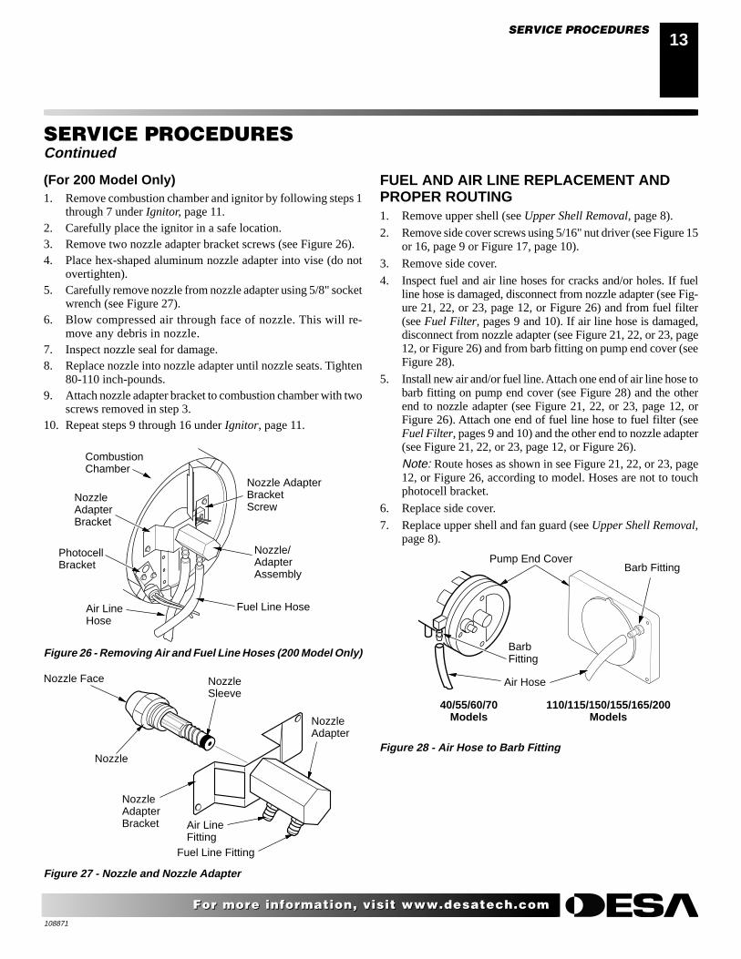
SERVICE PROCEDURES
Figure 26 - Removing Air and Fuel Line Hoses (200 Model Only)
Fuel Line Hose
Nozzle/AdapterAssembly
CombustionChamber
NozzleAdapterBracket
PhotocellBracket
Air LineHose
Nozzle AdapterBracketScrew
Nozzle Face
Nozzle
NozzleSleeve
NozzleAdapterBracket Air Line
FittingFuel Line Fitting
Figure 27 - Nozzle and Nozzle Adapter
(For 200 Model Only)1. Remove combustion chamber and ignitor by following steps 1
through 7 under Ignitor, page 11.2. Carefully place the ignitor in a safe location.3. Remove two nozzle adapter bracket screws (see Figure 26).4. Place hex-shaped aluminum nozzle adapter into vise (do not
overtighten).5. Carefully remove nozzle from nozzle adapter using 5/8" socket
wrench (see Figure 27).6. Blow compressed air through face of nozzle. This will re-
move any debris in nozzle.7. Inspect nozzle seal for damage.8. Replace nozzle into nozzle adapter until nozzle seats. Tighten
80-110 inch-pounds.9. Attach nozzle adapter bracket to combustion chamber with two
screws removed in step 3.10. Repeat steps 9 through 16 under Ignitor, page 11.
NozzleAdapter
SERVICE PROCEDURESContinued
FUEL AND AIR LINE REPLACEMENT ANDPROPER ROUTING1. Remove upper shell (see Upper Shell Removal, page 8).
2. Remove side cover screws using 5/16" nut driver (see Figure 15or 16, page 9 or Figure 17, page 10).
3. Remove side cover.
4. Inspect fuel and air line hoses for cracks and/or holes. If fuelline hose is damaged, disconnect from nozzle adapter (see Fig-ure 21, 22, or 23, page 12, or Figure 26) and from fuel filter(see Fuel Filter, pages 9 and 10). If air line hose is damaged,disconnect from nozzle adapter (see Figure 21, 22, or 23, page12, or Figure 26) and from barb fitting on pump end cover (seeFigure 28).
5. Install new air and/or fuel line. Attach one end of air line hose tobarb fitting on pump end cover (see Figure 28) and the otherend to nozzle adapter (see Figure 21, 22, or 23, page 12, orFigure 26). Attach one end of fuel line hose to fuel filter (seeFuel Filter, pages 9 and 10) and the other end to nozzle adapter(see Figure 21, 22, or 23, page 12, or Figure 26).
Note: Route hoses as shown in see Figure 21, 22, or 23, page12, or Figure 26, according to model. Hoses are not to touchphotocell bracket.
6. Replace side cover.
7. Replace upper shell and fan guard (see Upper Shell Removal,page 8).
Figure 28 - Air Hose to Barb Fitting
Barb Fitting
Air Hose
Pump End Cover
BarbFitting
110/115/150/155/165/200Models
40/55/60/70Models
108871
14
For more information, visit www.desatech.comFor more information, visit www.desatech.com
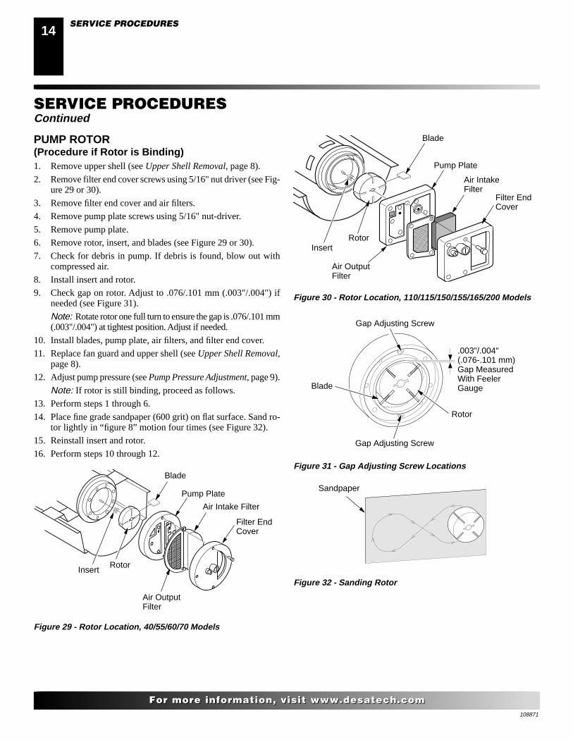
PUMP ROTOR(Procedure if Rotor is Binding)1. Remove upper shell (see Upper Shell Removal, page 8).
2. Remove filter end cover screws using 5/16" nut driver (see Fig-ure 29 or 30).
3. Remove filter end cover and air filters.
4. Remove pump plate screws using 5/16" nut-driver.
5. Remove pump plate.
6. Remove rotor, insert, and blades (see Figure 29 or 30).
7. Check for debris in pump. If debris is found, blow out withcompressed air.
8. Install insert and rotor.
9. Check gap on rotor. Adjust to .076/.101 mm (.003"/.004") ifneeded (see Figure 31).
Note: Rotate rotor one full turn to ensure the gap is .076/.101 mm(.003"/.004") at tightest position. Adjust if needed.
10. Install blades, pump plate, air filters, and filter end cover.
11. Replace fan guard and upper shell (see Upper Shell Removal,page 8).
12. Adjust pump pressure (see Pump Pressure Adjustment, page 9).
Note: If rotor is still binding, proceed as follows.
13. Perform steps 1 through 6.
14. Place fine grade sandpaper (600 grit) on flat surface. Sand ro-tor lightly in “figure 8” motion four times (see Figure 32).
15. Reinstall insert and rotor.
16. Perform steps 10 through 12.
SERVICE PROCEDURESContinued
Figure 29 - Rotor Location, 40/55/60/70 Models
Figure 30 - Rotor Location, 110/115/150/155/165/200 Models
Insert
Blade
Rotor
Pump Plate
Air IntakeFilter
Air OutputFilter
Pump Plate
InsertRotor
Blade
Filter EndCover
Air Intake Filter
Air OutputFilter
Filter EndCover
Gap Adjusting Screw
Rotor
Blade
.003"/.004"(.076-.101 mm)Gap MeasuredWith FeelerGauge
Gap Adjusting Screw
Figure 31 - Gap Adjusting Screw Locations
Sandpaper
Figure 32 - Sanding Rotor
SERVICE PROCEDURES

108871
1515
For more information, visit www.desatech.comFor more information, visit www.desatech.com
SERVICE PROCEDURESContinued
IGNITION CONTROL ASSEMBLY
WARNING: High voltage!
SERVICE PROCEDURESTECHNICAL SERVICE
REPLACEMENT PARTS
Figure 34 - Replacing Fuse
Fuse
FuseCoverFuse Clips
1. Unplug heater.
2. Remove side cover screws (4) using 5/16" nut-driver to ex-pose ignition control assembly.
3. Remove fuse cover (see Figure 33).
4. Remove fuse from fuse clips (see Figure 33).
5. Replace fuse with fuse of the same type and rating (GMA-10).Do not substitute a fuse with a higher current rating.
6. Replace fuse cover (see Figure 33).
7. Replace side cover (see Figures 15 or 16, page 9 or Figure 17,page 10).
TECHNICAL SERVICEYou may have further questions about installation, operation, ortroubleshooting.
If so, contact DESA International’s Technical Service Departmentat 1-866-672-6040.
You can also visit DESA International’s technical services web siteat www.desatech.com.
REPLACEMENT PARTSNote: Use only original replacement parts. This will protect yourwarranty coverage for parts replaced under warranty.
PARTS UNDER WARRANTYContact authorized dealers of this product. If they can’t supplyoriginal replacement part(s), call DESA International’s TechnicalService Dept. at 1-866-672-6040.
When calling DESA International, have ready:
• your name
• your address
• model and serial numbers of your heater
• how heater was malfunctioning
• purchase date
Usually, we will ask you to return the part to the factory.
PARTS NOT UNDER WARRANTYContact authorized dealers of this product. If they can’t supply originalreplacement part(s), call DESA International at 1-866-672-6040 forreferral information. Parts dealers are listed in the Authorized ServiceCenter booklet supplied with heater.
When calling DESA International, have ready:
• model and serial numbers of your heater
• the replacement part number

108871
16
For more information, visit www.desatech.comFor more information, visit www.desatech.com
WIRING DIAGRAMS
SPECIFICATIONSWIRING DIAGRAMS
Power Plug120V/60Hz
Blue
Blue
White
White
Photocell
Green
Green
Red
Black
Yellow
Yello
w
Motor
Ignitor
Igni
tion
Con
trol
Ass
embl
y
Photocell
Photocell
Ignitor
Motor Return
AC Neutral (L2)
120V (L1)
Ignitor
Motor
Figure 34 - Wiring Diagram without Thermostat (40/55/60/70/110/115/150/155/165 Models)
Model Size 40 55/60 70 110/115 150/155 165 200
Output Rating (Btu/Hr) 40,000 55,000 70,000 110,000 150,000 165,000 200,000and 60,000 and 115,000 and 155,000
Fuel Use only kerosene, #1/#2 diesel/fuel oil, JET A or JP-8 fuels*
Fuel Tank Capacity(U.S. Gal./Liters) 3/11.3 5/18.9 5/18.9 9/34 13.5/51 13.5/51 13.5/51
Fuel Consumption(Gal. Per Hr/Liters Per Hr) .3/1.14 .44/1.67 .52/1.97 .85/3.00 1.14/4.31 1.2/4.54 1.4/5.3
Pump Pressure (psi) 3.0 3.4 4.7 5.3 5.4 5.6 6.2
Electric Requirements 120 V/60 HZ (Same All Models)
Amperage (Normal Run) 2.0 2.0 2.8 3.6 3.6 3.6 3.6
Motor RPM 1725 1725 3440 3400 3400 3400 3400
Hot Air Output (CFM) 170 180 360 490 550 575 600
Motor HP 1/15 1/15 1/8 1/5 1/5 1/5 1/4
Shipping Weight 32/14.5 33/15 35/15.9 54/24.5 63/28.6 65/29.5 77/35(Approximate Pounds/Kilograms)
Heater Weight without Fuel 28/12.7 29/13.1 31/14 46/21 54/24.5 55/25 66/30(Approximate Pounds/Kilograms)
* Use of #2 diesel & fuel oil will result in noticeable odor and could require additional fuel filter maintenance. Use in extreme coldtemperatures may require nontoxic anti-icer additives.
SPECIFICATIONS

108871
1717
For more information, visit www.desatech.comFor more information, visit www.desatech.com
Power Plug120V/60Hz
Blue
Blue
White
WhitePhotocell
Igni
tion
Con
trol
Ass
embl
y
Green
Green
Red
Black
Bla
ck
Yellow
Yello
w
Motor
Ignitor
Thermostat
Photocell
Photocell
Ignitor
Motor Return
AC Neutral (L2)
120V (L1)
Ignitor
Motor
Figure 36 - Wiring Diagram with Thermostat (40/55/60/70/110/115/150/155/165 Models)
Pow
er Plug
120V/60H
z
BluePhotocell
Photocell
Ignitor
Motor Return
AC Neutral (L2)
AC Hot (L1)
Motor
Ignitor
Blue
White
White
White
White
Photocell
Igni
tion
Con
trol
Ass
embl
y
GreenGreen
RedRedRed
Bla
ck
Bla
ck
Yellow
Yello
wMotor
Ignitor
SolenoidValve
Thermostat
Figure 35 - Wiring Diagram with Thermostat for 200 Model
WIRING DIAGRAMS (Cont.)
Pow
er Plug
120V/60H
z
BluePhotocell
Photocell
Ignitor
Motor Return
AC Neutral (L2)
AC Hot (L1)
Motor
Ignitor
Blue
White
White
WhiteWhite
PhotocellIgnition C
ontrol Assem
bly
Green Green
Red
RedRed
Black
Black
BlackMotor
Ignitor
SolenoidValve
WIRING DIAGRAMSContinued
Figure 37 - Wiring Diagram without Thermostat for 200 Model

108871
18
For more information, visit www.desatech.comFor more information, visit www.desatech.com
1
2
3
4
5
67
8
9
10
11
12
13
1415
16
17
18
19
20
21
22
23
24
25
26
27
28
29
30
33
34
35
31 32
38
37
36
9-2
9-1
9-39-4
9-5
ILLUSTRATED PARTSBREAKDOWN40/55/60/70 MODELS
Motor and Pump Assembly
12-11
12-18
12-1712-16
12-15
12-1412-13
12-12
12-10
12-1
12-3
12-4
12-5
12-6
12-712-8
12-9
12-2
12-19
ILLUSTRATED PARTS BREAKDOWN40/55/60/70 Models
Standard ThermostatModels ModelsR40 R40TREM40 R55BTR55B B55BTR60 R70DTREM60 B70DTRM60

108871
1919
For more information, visit www.desatech.comFor more information, visit www.desatech.com
PARTS LIST40/55/60/70 MODELS
This list contains replaceable parts used in your heater. When ordering parts, be sure toprovide the correct model and serial numbers (from the model plate), then the part numberand description of the desired part.
PARTS LIST40/55/60/70 Models
KEY PARTNO. NUMBER DESCRIPTION QTY.
1 M51104-01 Handle 12 098511-67 Upper Shell (Service Part 1
Will Be Black)3 M11084-29 Screw, #10-16 x 3/4" 24 100647-01 Screw, #10-16 x 1 1/2" 65 098512-58 Combustion Chamber (40) 1
098512-50 Combustion Chamber (55/60) 1098512-51 Combustion Chamber (70) 1
6 M10908-2 Screw, #6-32 x 3/8" 27 103154-03 Photocell Bracket 18 M16656-24 Photocell Assembly 19 ∆ Burner Head Assembly 9-1 HA3006 Nozzle Assembly (40) 1
HA3024 Nozzle Assembly (55/60) 1 HA3026 Nozzle Assembly (70) 1
9-2 102548-03 Ignitor Kit 1 9-3 104056-01 Nozzle Adapter 1 9-4 102336-01 Nozzle Adapter Bracket 1 9-5 M10908-75 Screw, Hex Head, Tapping 1 9-6 103347-01 Belleville Washer 110 107992-01 Screw, #10-16 x 3/8" 211 103684-01 Fan (40/55/60) 1
M29678 Fan (70) 112 ∆ Motor and Pump Assembly 12-1 102001-01 Motor (40/55/60) 1
102001-20 Motor (70) 1 12-2 079975-03 Pump Body (55/60) 1
079975-02 Pump Body (40/70) 1 12-3 M22009**, *** Insert 1 12-4 M22456-2** Rotor (55/60) 1
M22456-1*** Rotor (40/70) 1 12-5 M29608 Pump End Cover 1 12-6 M29632 ⊕ Lint Filter 1 12-7 M29633 ⊕ Intake Filter 1 12-8 M29609 Filter End Cover 1 12-9 M12461-31 Screw, #10-32 x 1" 3 12-10 M27694 ∞ Adjusting Screw 1 12-11 M10993-1 ∞ Pressure Relief Spring 1 12-12 M22997 ∞ Plug 1 12-13 M8940 ∞ Steel Ball, 1/4" Diameter 1 12-14 M29612-01 ⊕ Output Filter 1 12-15 M12461-32 Screw, #10-32 x 1 1/8" (55/60) 6
M12461-31 Screw, #10-32 x 1" (40/70) 6 12-16 103676-01 Nylon Elbow, 90° 1 12-17 M8643-2** Blade (55/60) 4
M8643*** Blade (40/70) 4
KEY PARTNO. NUMBER DESCRIPTION QTY.
∆ Not available as an assembly ⊕ Included in Filter Kit (Part No. HA3014)** Included in Rotor Kit (Part No. HA3005) ∞ Included in Pump Adjustment Kit (Part No. HA3020)*** Included in Rotor Kit (Part No. HA3004)
12-18 FHPF3-6C Screw, #10-32 x 3/4" (55/60) 2 FHPF3-5C Screw, #10-32 x 5/8" (40/70) 2
12-19 105780-01 Plastic Cap 113 M51105-01 Fan Guard 114 098219-38 Power Cord 115 M11143-1 Strain Relief Bushing 116 NTC-4C Hex Lock Nut, 1/4-20 217 107992-01 Screw, #10-16 x 3/8" 418 M50631 Rubber Bumper 219 097461-09 Side Cover 120 101205-01 Motor Bracket 121 M50104-06 Bushing 122 M11271-8 Clip Nut 623 M50104-02 Bushing 124 107992-01 Screw, #10-16 x 3/8" 625 M10908-14 Screw, #8-32 x 3/8" 126 098511-234 Lower Shell (Service Part 1
Will Be Black) 127 M50814-06 Rubber Airline 128 079973-01 Fuel Line 129 M50876-04 Fuel Filter with bushing (40) 1
M50876-05 Fuel Filter with bushing (55/60/70) 1
30 M10990-3 Rubber Bushing 131 102349-01 PCB Support 532 104068-02 Ignition Control Assembly 133 097702-01 Fuel Cap (Includes Gasket) 134 108088-01 Fuel Tank (40) 1
108088-03 Fuel Tank (55/60/70) 135 M51108-01 Shell Heat-Shield 136 104458-01 Thermostat (40/55/60) 1
097657-03 Thermostat (70) 137 M12461-18 Screw, #8-32 x 7/8" (40/55/60) 1
M10908-1 Screw, #6-32 x 1/4" (70) 238 104460-01 Thermostat Knob (40/55/60) 1
104905-01 Thermostat Knob (70) 1
PARTS AVAILABLE - NOT SHOWN
100621-06 Thermostat Decal 1103814-01 Wire Tie (For Ignition
Control Assembly) 1M9900-170 Wire Assembly
(Thermostat to Ignition Control Assembly 40/55/60) 1

108871
20
For more information, visit www.desatech.comFor more information, visit www.desatech.com
ILLUSTRATED PARTSBREAKDOWN110/115/150/155/165 MODELS
ILLUSTRATED PARTS BREAKDOWN110/115/150/155/165 Models
1
2
3
23 19
9
10
16
11
12
15
25
27
24
28
29
20
22
21
30
31
17
14
14
33
34
35
36
32
2618
54
6
7
8
7-2
7-1
7-57-4
7-3
37
13
38
7-6
Motor and Pump Assembly 10-11
10-17
10-16
10-15
10-1410-13
10-12
10-10
10-1
10-2
10-3
10-410-5
10-6
10-710-8
10-9
10-1310-18
Standard ThermostatModels ModelsR110B R110BTR115 B110BTREM115 SB115TRM115 SB150JTREM150E B155TREM155B R165ATRM155R155B

108871
2121
For more information, visit www.desatech.comFor more information, visit www.desatech.com
PARTS LIST110/115/150/155/165 MODELS
This list contains replaceable parts used in your heater. When ordering parts, be sure toprovide the correct model and serial numbers (from the model plate), then the part numberand description of the desired part.
PARTS LIST110/115/150/155/165 Model
KEY PARTNO. NUMBER DESCRIPTION QTY.
KEY PARTNO. NUMBER DESCRIPTION QTY.
1 098511-66 Upper Shell (Service Part Will Be Black) 1
2 100647-01 Screw, #10-16 x 1/2" 83 098512-54 Combustion Chamber (110/115) 1
098512-59 Combustion Chamber (150/155) 1098512-60 Combustion Chamber (165) 1
4 103971-01 Photocell Bracket (110/115) 1103154-05 Photocell Bracket (150/155/165) 1
5 M10908-2 Screw, #6-32 x 3/8" 26 M16656-24 Photocell Assembly 17 ∆ Burner Head Assembly 1 7-1 HA3027 Nozzle Assembly (110/115) 1
HA3028 Nozzle Assembly (150/155) 1 HA3029 Nozzle Assembly (165) 1
7-2 102548-03 Ignitor Kit 1 7-3 M10908-75 Screw 1 7-4 102336-01 Nozzle Adapter Bracket 1 7-5 104054-01 Nozzle Adapter 1 7-6 103347-01 Washer 18 107992-01 Screw, #10-16 x 3/8" 29 097293-01 Fan (110/115) 1
102042-01 Fan (150/155/165) 110 ∆ Motor and Pump Assembly 1 10-1 102001-21 Motor 1 10-2 079975-02 Pump Body 1 10-3 FHPF3-5C Screw, #10-32 x 5/8" 2 10-4 M22009** Rotor Insert 1 10-5 M22456-1** Pump Rotor 1 10-6 M50545 Pump End Cover 1 10-7 M12179*** Intake Filter 1 10-8 M16545 Filter End Cover 1 10-9 M8940∞ Steel Ball, 1/4" Diameter 1 10-10 M10993-1∞ Relief Spring 1 10-11 M27694∞ Adjusting Screw 1 10-12 M22997∞ Plug 1 10-13 M12461-31 Screw, #10-32 x 1" 10 10-14 M12244-1*** Output Filter 1 10-15 M11637*** Lint Filter 1
10-16 104096-01 Fitting, Straight Nylon Barb 1 10-17 M8643** Blade 4 10-18 105780-01 Plastic Cap 111 M50631 Rubber Bumper 212 101206-01 Motor Mounting Bracket 113 M10908-1 Screw, #6-32 x 1/4" 214 104068-02 Ignition Control Assembly 115 NTC-4C Hex Lock Nut, 1/4-20 216 M51114-01 Fan Guard 117 M27417 Drain Plug (Includes “o” Ring) 118 099213-01 Button Plug 119 M51345-06 Fuel Line 120 M51150-01*** Fuel Filter 121 M51151-01 Fuel Line Tube (110/115) 1
M51151-02 Fuel Line Tube (150/155/165) 122 M10990-3 Rubber Bushing 123 M50814-03 Airline 124 098511-236 Lower Shell (Service Part Will
Be Black) 125 M50104-03 Bushing 126 M50104-01 Bushing 127 107992-01 Screw, #10-16 x 3/8" 628 M11271-8 Clip Nut 829 M10908-14 Screw, #8-32 x 3/8" 130 108088-04 Fuel Tank (110/115) 1
108088-05 Fuel Tank (150/155/165) 131 097702-01 Fuel Cap (Includes Gasket) 132 102349-01 P.C. Board Support 533 M11143-1 Strain Relief Bushing 134 098219-38 Power Cord 135 M51077-09AA Side Cover 136 107992-01 Screw, #10-16 x 3/8" 437 104905-01 Thermostat Knob 138 097657-03 Thermostat 1
103814-01 Wire Tie (Not Shown) - Groups 1 wires connected to Ignition Control Assembly
100621-06 Thermostat Decal (Not Shown) 1
∆ Not available as an assembly ∗∗∗ Included in Filter Kit (Part No. HA3017)** Included in Rotor Kit (Part No. HA3004) ∞ Included in Pump Adjustment Kit (Part No. HA3020)

108871
22
For more information, visit www.desatech.comFor more information, visit www.desatech.com
ILLUSTRATED PARTSBREAKDOWN200 MODELS
ILLUSTRATED PARTS BREAKDOWN200 Models
1
2
3
23 19
9
10
11
12
1315
25
27
24
28
29
30
31
17
14
14
33
34
35
36
32
26
54
6
7
8
16
18
37
38
20
2221
39
42
41
40
43
Motor and Pump Assembly
10-1
10-2
10-3
10-4 10-5
10-6
10-710-8
10-910-10
10-1110-12
10-18 10-14
10-15
10-16
10-17
10-13
Fuel Valve Assembly
Nozzle Assembly
7-1
7-8
7-77-3
7-4
7-5
7-6
7-2
7-11
7-10
7-9
39-4
39-4
39-3
39-5
39-2
39-1
39-6
39-7
10-19
Standard ThermostatModels ModelsR200A R200AT
RM200ATB200ATREM200AT

108871
2323
For more information, visit www.desatech.comFor more information, visit www.desatech.com
13 097785-04 Foam Gasket 214 104068-02 Ignition Control Assembly 115 NTC-4C Hex Lock Nut, 1/4-20 216 102756-01 Fan Guard 117 M27417 Drain Plug (Includes “o” Ring) 118 103523-01 Rubber Bushing 119 M51345-03 Fuel Line 120 M51150-01*** Fuel Filter 121 M51345-04 Fuel Line Tube 122 M10990-3 Rubber Bushing 123 M50814-03 Airline 124 107353-11 Lower Shell (Service Part
Will Be Black) 125 M30865-02 Bushing 126 M50104-01 Bushing 127 107992-01 Screw, #10-16 x 3/8" 628 M11271-8 Clip Nut 829 M10908-14 Screw, #8-32 x 3/8" 130 108088-06 Fuel Tank 131 097702-01 Fuel Cap (Includes Gasket) 132 102349-01 P.C. Board Support 533 M11143-1 Strain Relief Bushing 134 098219-38 Power Cord 135 107333-04AA Side Cover 136 107992-01 Screw, #10-16 x 3/8" 437 099230-01 Screw, Special 238 M11084-27 Screw, #10-16 x 1/2" 239 ∆ Fuel Valve Assembly 1 39-1 107643-01 Fuel Valve 1 39-2 107336-01 Fuel Valve Bracket 1 39-3 M12461-13 Hex Head Screw, #8-32 x 1/4" 2 39-4 M50820-02 Fitting Barb 2 39-5 102432-01 Screw Hex Hd Sems Ext "B"
#10-16 x 1/2" 2 39-6 107274-01 Wire Assembly, Red 1 39-7 107274-02 Wire Assembly, White 140 097657-03 Thermostat 141 M10908-1 Screw, #6-32 x 1/4" 242 104905-01 Thermostat Knob 143 079010-35 Wire Assembly 1
103814-01 Wire Tie (Not Shown) 1 (For Ignition Control Assembly)
100621-06 Thermostat Decal (Not Shown) 1
KEY PARTNO. NUMBER DESCRIPTION QTY.
1 107353-10 Upper Shell (Service Part Will Be Black) 1
2 100647-01 Screw, #10-16 x 1/2" 83 098512-69 Combustion Chamber 14 103154-05 Photocell Bracket 15 M10908-2 Screw, #6-32 x 3/8" 26 M16656-24 Photocell Assembly 17 ∆ Burner Head Assembly 1 7-1 100735-13 Nozzle Assembly 1 7-2 M10659-1 Nozzle Washer 2 7-3 M10809-1 Nozzle Spring 1 7-4 M8882 Nozzle Sleeve 1 7-5 107272-01 Retaining Ring 1 7-6 102336-03 Nozzle Adapter Bracket 1 7-7 102548-06 Ignitor Kit 1 7-8 103347-01 Belleville Washer 1 7-9 M10908-75 Screw, #6-32 x .88 1 7-10 107273-01 Nozzle Adapter 1 7-11 M50820-02 Barb Fitting 18 107992-01 Screw, #10-16 x 3/8" 29 102042-01 Fan 110 ∆ Motor and Pump Assembly 1 10-1 102001-27 Motor 1 10-2 079975-03 Pump Body 1 10-3 FHPF3-6C Screw, #10-32 x 5/8" 2 10-4 M22009** Rotor Insert 1 10-5 M22456-2** Pump Rotor 1 10-6 M50545 Pump End Cover 1 10-7 M12179*** Intake Filter 1 10-8 M16545 Filter End Cover 1 10-9 M8940∞ Steel Ball, 1/4" Diameter 1 10-10 M10993-1∞ Relief Spring 1 10-11 M27694∞ Adjusting Screw 1 10-12 M22997∞ Plug 1 10-13 M12461-31 Screw, #10-32 x 1" 4 10-14 M12244-1*** Output Filter 1 10-15 M11637*** Lint Filter 1 10-16 M50820-02 Barb Fitting 1 10-17 M8643-2** Blade 4 10-18 M12461-32 Screw, #10-32 x 1.12" 6 10-19 105780-01 Plastic Cap 111 M50631 Rubber Bumper 212 101206-01 Motor Mounting Bracket 1
PARTS LIST200 MODELS
PARTS LIST200 Models
KEY PARTNO. NUMBER DESCRIPTION QTY.
∆ Not available as an assembly ∗∗∗ Included in Filter Kit (Part No. HA3017)** Included in Rotor Kit (Part No. HA3005) ∞ Included in Pump Adjustment Kit (Part No. HA3020)
108871
24
For more information, visit www.desatech.comFor more information, visit www.desatech.com
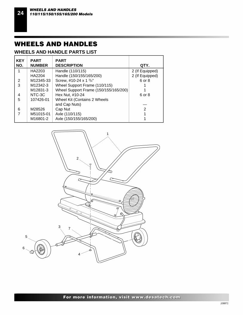
WHEELS AND HANDLES
WHEELS AND HANDLES110/115/150/155/165/200 Models
WHEELS AND HANDLE PARTS LIST
KEY PART PARTNO. NUMBER DESCRIPTION QTY.1 HA2203 Handle (110/115) 2 (If Equipped)
HA2204 Handle (150/155/165/200) 2 (If Equipped)2 M12345-33 Screw, #10-24 x 1 3/4" 6 or 83 M12342-3 Wheel Support Frame (110/115) 1
M12831-3 Wheel Support Frame (150/155/165/200) 14 NTC-3C Hex Nut, #10-24 6 or 85 107426-01 Wheel Kit (Contains 2 Wheels
and Cap Nuts) —6 M28526 Cap Nut 27 M51015-01 Axle (110/115) 1
M16801-2 Axle (150/155/165/200) 1
1
2
3
4
5
7
6

108871
2525
For more information, visit www.desatech.comFor more information, visit www.desatech.com
ACCESSORIES
ACCESSORIESPurchase accessories and parts from your nearest dealer or servicecenter. If they can not supply these accessories or parts, either contactyour nearest parts dealer or DESA International at 1-800-458-2472for referral information. Parts Centrals are listed in the AuthorizedService Center booklet supplied with heater.
HEAVY DUTY WHEELS AND HANDLE KITHA1202For heavy duty applications. Makes your heater even more portableand convenient.
AIR GAUGE KIT - HA1180For all models. Special tool to check pump pressure.
STANDARD WHEELS AND HANDLE KITHA1206Makes heater even more portable and convenient. Easy to assemble.
A 008
IGNITION CONTROL ASSEMBLY/PHOTOCELLTESTER - HA1170Special tool used to test the ignition control assembly and photocell.
THERMOSTAT KIT - HA1210Keeps your building at the temperature you select day and night.Helps economize on fuel.
FUEL TANK FILLER NECK SCREEN - HA2210This screen/filter drops in fuel tank filler neck. This prefilter allowsfor easy cleaning and provides two-stage filtering advantage.

108871
26
For more information, visit www.desatech.comFor more information, visit www.desatech.com
WARRANTY AND REPAIR SERVICE
Printed in U.S.A.
108871-01Rev. C09/01
WARRANTY SERVICE
Should your heater require service, return it to your nearest authorized service center. Proof of purchase must be presented with the heater. Theheater will be inspected. A defect may be caused by faulty materials or workmanship. If so, DESA International will repair or replace the heaterwithout charge.
REPAIR SERVICE
Return the heater to your nearest authorized service center. Each Service Center is independently owned and operated. Repairs not covered by thewarranty will be billed at standard prices. We reserve the right to amend these specifications at any time without notice.
Illustrated parts lists can be obtained free of charge. Send a self addressed stamped envelope to the address listed below. List the heater modelnumber and the date located in the lower right corner of this page. A service manual may be purchased from the address listed below. Send a checkfor $5.00 payable to DESA International.
When writing for information regarding your heater, be sure to include the model number and serial number as shown on the model plate.
For more information about this warranty, write:
LIMITED WARRANTY
DESA International warrants this product and any parts thereof, to be free from defects in materials and workmanship for one (1) year from thedate of first purchase when operated and maintained in accordance with instructions. This warranty is extended only to the original retailpurchaser, when proof of purchase is provided.
This warranty covers only the cost of parts and labor required to restore the product to proper operating condition. Transportation and incidentalcosts associated with warranty repairs are not reimbursable under this warranty.
Warranty service is available only through authorized dealers and service centers.
This warranty does not cover defects resulting from misuse, abuse, negligence, accidents, lack of proper maintenance, normal wear, alteration,modification, tampering, contaminated fuels, repair using improper parts, or repair by anyone other than an authorized dealer or service center.Routine maintenance is the responsibility of the owner.
THIS EXPRESS WARRANTY IS GIVEN IN LIEU OF ANY OTHER WARRANTY EITHER EXPRESSED OR IMPLIED, INCLUDINGWARRANTIES OF MERCHANTABILITY AND FITNESS FOR A PARTICULAR PURPOSE.
DESA International assumes no responsibility for indirect, incidental or consequential damages. Some states do not allow the exclusion orlimitation of incidental or consequential damages or limitations or exclusions may not apply to you. This Limited Warranty gives you specificlegal rights and you may also have other rights which vary from state to state.
2701 Industrial DriveP.O. Box 90004Bowling Green, KY 42102-9004
www.desatech.com
NOT A UPC
108871 01
TM