Embed Size (px)
Citation preview
Portable Hydraulic Dynamometer
Product Catalog
Copyright © Tokyo Plant Co., Ltd.
Last update on 2018/04/12
Advanced Test System and Test Bed Engineering Professional
Copyright © Tokyo Plant Co., Ltd.
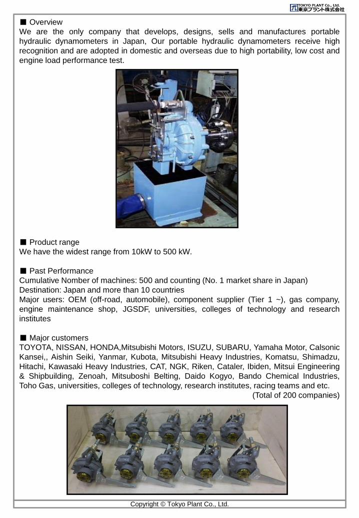
■ Overview
We are the only company that develops, designs, sells and manufactures portable
hydraulic dynamometers in Japan, Our portable hydraulic dynamometers receive high
recognition and are adopted in domestic and overseas due to high portability, low cost and
engine load performance test.
■ Product range
We have the widest range from 10kW to 500 kW.
■ Past Performance
Cumulative Nomber of machines: 500 and counting (No. 1 market share in Japan)
Destination: Japan and more than 10 countries
Major users: OEM (off-road, automobile), component supplier (Tier 1 ~), gas company,
engine maintenance shop, JGSDF, universities, colleges of technology and research
institutes
■ Major customers
TOYOTA, NISSAN, HONDA,Mitsubishi Motors, ISUZU, SUBARU, Yamaha Motor, Calsonic
Kansei,, Aishin Seiki, Yanmar, Kubota, Mitsubishi Heavy Industries, Komatsu, Shimadzu,
Hitachi, Kawasaki Heavy Industries, CAT, NGK, Riken, Cataler, Ibiden, Mitsui Engineering
& Shipbuilding, Zenoah, Mitsuboshi Belting, Daido Kogyo, Bando Chemical Industries,
Toho Gas, universities, colleges of technology, research institutes, racing teams and etc.
(Total of 200 companies)
■ Characteristics
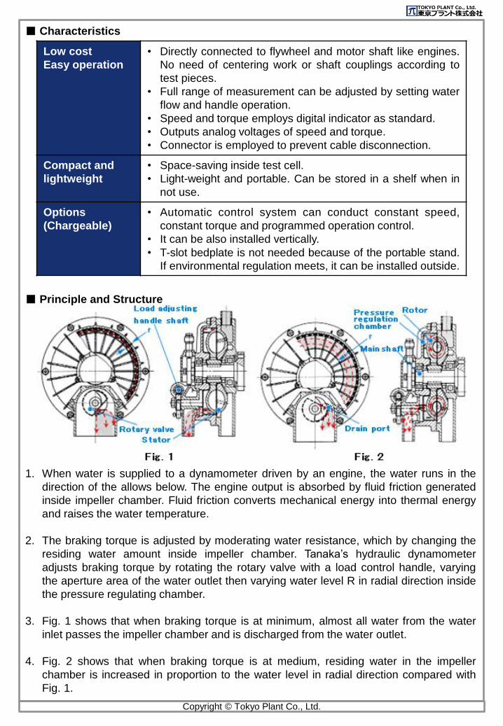
■ Principle and Structure
1. When water is supplied to a dynamometer driven by an engine, the water runs in the
direction of the allows below. The engine output is absorbed by fluid friction generated
inside impeller chamber. Fluid friction converts mechanical energy into thermal energy
and raises the water temperature.
2. The braking torque is adjusted by moderating water resistance, which by changing the
residing water amount inside impeller chamber. Tanaka’s hydraulic dynamometer
adjusts braking torque by rotating the rotary valve with a load control handle, varying
the aperture area of the water outlet then varying water level R in radial direction inside
the pressure regulating chamber.
3. Fig. 1 shows that when braking torque is at minimum, almost all water from the water
inlet passes the impeller chamber and is discharged from the water outlet.
4. Fig. 2 shows that when braking torque is at medium, residing water in the impeller
chamber is increased in proportion to the water level in radial direction compared with
Fig. 1.
Low cost
Easy operation
• Directly connected to flywheel and motor shaft like engines.
No need of centering work or shaft couplings according to
test pieces.
• Full range of measurement can be adjusted by setting water
flow and handle operation.
• Speed and torque employs digital indicator as standard.
• Outputs analog voltages of speed and torque.
• Connector is employed to prevent cable disconnection.
Compact and
lightweight
• Space-saving inside test cell.
• Light-weight and portable. Can be stored in a shelf when in
not use.
Options
(Chargeable)
• Automatic control system can conduct constant speed,
constant torque and programmed operation control.
• It can be also installed vertically.
• T-slot bedplate is not needed because of the portable stand.
If environmental regulation meets, it can be installed outside.
Copyright © Tokyo Plant Co., Ltd.
■ Applications
〇 Targets
• Marine engine
• Agricultural machine engine
• Construction vehicle engine
• Generator
• Small turbine
• Pump
• Passenger cars
• Motor
• Truck engine
• Motorcycle engine
• Gear box
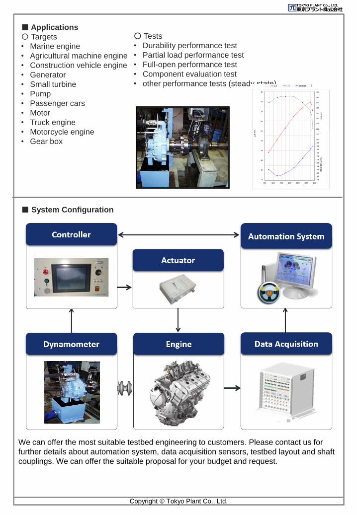
■ System Configuration
○ Tests
• Durability performance test
• Partial load performance test
• Full-open performance test
• Component evaluation test
• other performance tests (steady state)...
We can offer the most suitable testbed engineering to customers. Please contact us for
further details about automation system, data acquisition sensors, testbed layout and shaft
couplings. We can offer the suitable proposal for your budget and request.
Copyright © Tokyo Plant Co., Ltd.
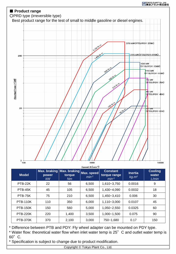
■ Product range
○PRD type (irreversible type)
Best product range for the test of small to middle gasoline or diesel engines.
Model
Max. braking
power
kW
Max. braking
torque
Nm
Max. speed
min-1
Constant
torque range
min-1
Inertia
kg.m²
Cooling
water
L/min
PTB-22K 22 56 6,500 1,610~3,750 0.0016 9
PTB-45K 45 105 6,500 1,430~4,090 0.0032 18
PTB-75K 75 210 6,500 1,450~3,410 0.006 30
PTB-110K 110 350 6,000 1,110~3,000 0.0107 45
PTB-150K 150 560 5,000 1,050~2,550 0.0325 60
PTB-220K 220 1,400 3,500 1,000~1,500 0.075 90
PTB-370K 370 2,100 3,000 750~1,680 0.17 150
Copyright © Tokyo Plant Co., Ltd.
* Difference between PTB and PDY: Fly wheel adapter can be mounted on PDY type.
* Water flow: theoretical water flow when inlet water temp is 25°C and outlet water temp is
60°C.
* Specification is subject to change due to product modification.
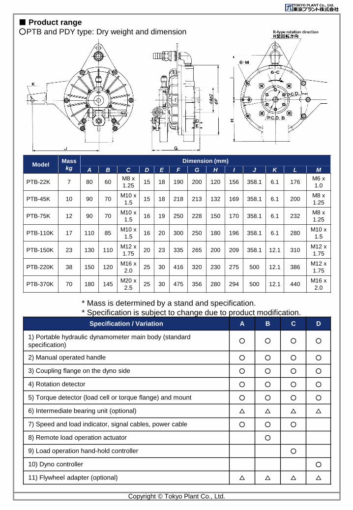
Specification / Variation A B C D
1) Portable hydraulic dynamometer main body (standard
specification)○ ○ ○ ○
2) Manual operated handle ○ ○ ○ ○
3) Coupling flange on the dyno side ○ ○ ○ ○
4) Rotation detector ○ ○ ○ ○
5) Torque detector (load cell or torque flange) and mount ○ ○ ○ ○
6) Intermediate bearing unit (optional) △ △ △ △
7) Speed and load indicator, signal cables, power cable ○ ○ ○
8) Remote load operation actuator ○
9) Load operation hand-hold controller ○
10) Dyno controller ○
11) Flywheel adapter (optional) △ △ △ △
■ Product range
○PTB and PDY type: Dry weight and dimension
ModelMass
kg
Dimension (mm)
A B C D E F G H I J K L M
PTB-22K 7 80 60M8 x
1.2515 18 190 200 120 156 358.1 6.1 176
M6 x
1.0
PTB-45K 10 90 70M10 x
1.515 18 218 213 132 169 358.1 6.1 200
M8 x
1.25
PTB-75K 12 90 70M10 x
1.516 19 250 228 150 170 358.1 6.1 232
M8 x
1.25
PTB-110K 17 110 85M10 x
1.516 20 300 250 180 196 358.1 6.1 280
M10 x
1.5
PTB-150K 23 130 110M12 x
1.7520 23 335 265 200 209 358.1 12.1 310
M12 x
1.75
PTB-220K 38 150 120M16 x
2.025 30 416 320 230 275 500 12.1 386
M12 x
1.75
PTB-370K 70 180 145M20 x
2.525 30 475 356 280 294 500 12.1 440
M16 x
2.0
Copyright © Tokyo Plant Co., Ltd.
* Mass is determined by a stand and specification.
* Specification is subject to change due to product modification.
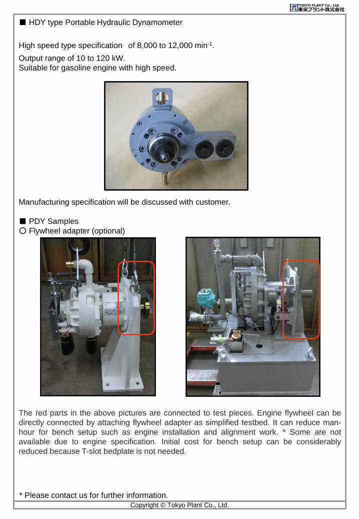
■ HDY type Portable Hydraulic Dynamometer
High speed type specification of 8,000 to 12,000 min-1.
Output range of 10 to 120 kW.
Suitable for gasoline engine with high speed.
Manufacturing specification will be discussed with customer.
■ PDY Samples
○ Flywheel adapter (optional)
The red parts in the above pictures are connected to test pieces. Engine flywheel can be
directly connected by attaching flywheel adapter as simplified testbed. It can reduce man-
hour for bench setup such as engine installation and alignment work. * Some are not
available due to engine specification. Initial cost for bench setup can be considerably
reduced because T-slot bedplate is not needed.
Copyright © Tokyo Plant Co., Ltd.
* Please contact us for further information.
Copyright © Tokyo Plant Co., Ltd.
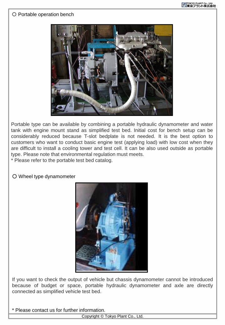
○ Wheel type dynamometer
* Please contact us for further information.
Portable type can be available by combining a portable hydraulic dynamometer and water
tank with engine mount stand as simplified test bed. Initial cost for bench setup can be
considerably reduced because T-slot bedplate is not needed. It is the best option to
customers who want to conduct basic engine test (applying load) with low cost when they
are difficult to install a cooling tower and test cell. It can be also used outside as portable
type. Please note that environmental regulation must meets.
* Please refer to the portable test bed catalog.
If you want to check the output of vehicle but chassis dynamometer cannot be introduced
because of budget or space, portable hydraulic dynamometer and axle are directly
connected as simplified vehicle test bed.
〇 Portable operation bench
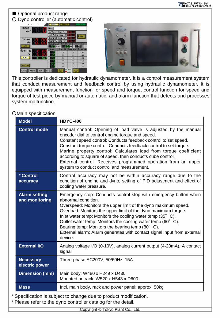
■ Optional product range
○ Dyno controller (automatic control)
This controller is dedicated for hydraulic dynamometer. It is a control measurement system
that conduct measurement and feedback control by using hydraulic dynamometer. It is
equipped with measurement function for speed and torque, control function for speed and
torque of test piece by manual or automatic, and alarm function that detects and processes
system malfunction.
○Main specification
Model HDYC-400
Control mode Manual control: Opening of load valve is adjusted by the manual
encoder dial to control engine torque and speed.
Constant speed control: Conducts feedback control to set speed.
Constant torque control: Conducts feedback control to set torque.
Marine property control: Calculates load from torque coefficient
according to square of speed, then conducts cube control.
External control: Receives programmed operation from an upper
system to conduct control and measurement.
* Control
accuracy
Control accuracy may not be within accuracy range due to the
condition of engine and dyno, setting of PID adjustment and effect of
cooling water pressure.
Alarm setting
and monitoring
Emergency stop: Conducts control stop with emergency button when
abnormal condition.
Overspeed: Monitors the upper limit of the dyno maximum speed.
Overload: Monitors the upper limit of the dyno maximum torque.
Inlet water temp: Monitors the cooling water temp (35°C).
Outlet water temp: Monitors the cooling water temp (60°C).
Bearing temp: Monitors the bearing temp (80°C).
External alarm: Alarm generates with contact signal input from external
device.
External I/O Analog voltage I/O (0-10V), analog current output (4-20mA), A contact
signal
Necessary
electric power
Three-phase AC200V, 50/60Hz, 15A
Dimension (mm) Main body: W480 x H249 x D430
Mounted on rack: W520 x H543 x D600
Mass Incl. main body, rack and power panel: approx. 50kg
* Specification is subject to change due to product modification.
* Please refer to the dyno controller catalog for the detail.
Copyright © Tokyo Plant Co., Ltd.
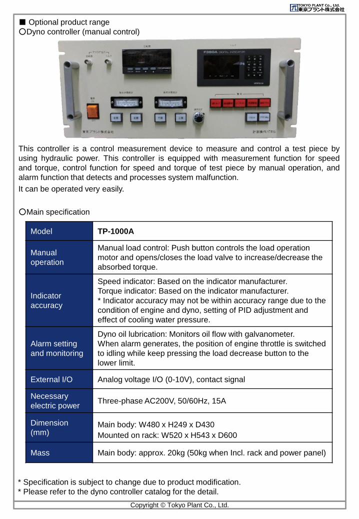
■ Optional product range
○Dyno controller (manual control)
This controller is a control measurement device to measure and control a test piece by
using hydraulic power. This controller is equipped with measurement function for speed
and torque, control function for speed and torque of test piece by manual operation, and
alarm function that detects and processes system malfunction.
It can be operated very easily.
○Main specification
Copyright © Tokyo Plant Co., Ltd.
Model TP-1000A
Manual
operation
Manual load control: Push button controls the load operation
motor and opens/closes the load valve to increase/decrease the
absorbed torque.
Indicator
accuracy
Speed indicator: Based on the indicator manufacturer.
Torque indicator: Based on the indicator manufacturer.
* Indicator accuracy may not be within accuracy range due to the
condition of engine and dyno, setting of PID adjustment and
effect of cooling water pressure.
Alarm setting
and monitoring
Dyno oil lubrication: Monitors oil flow with galvanometer.
When alarm generates, the position of engine throttle is switched
to idling while keep pressing the load decrease button to the
lower limit.
External I/O Analog voltage I/O (0-10V), contact signal
Necessary
electric powerThree-phase AC200V, 50/60Hz, 15A
Dimension
(mm)Main body: W480 x H249 x D430
Mounted on rack: W520 x H543 x D600
Mass Main body: approx. 20kg (50kg when Incl. rack and power panel)
* Specification is subject to change due to product modification.
* Please refer to the dyno controller catalog for the detail.
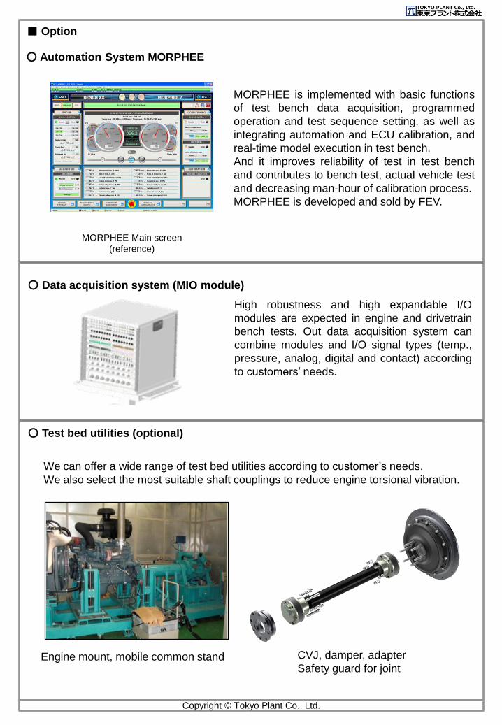
■ Option
○ Data acquisition system (MIO module)
○ Test bed utilities (optional)
○ Automation System MORPHEE
MORPHEE is implemented with basic functions
of test bench data acquisition, programmed
operation and test sequence setting, as well as
integrating automation and ECU calibration, and
real-time model execution in test bench.
And it improves reliability of test in test bench
and contributes to bench test, actual vehicle test
and decreasing man-hour of calibration process.
MORPHEE is developed and sold by FEV.
MORPHEE Main screen
(reference)
High robustness and high expandable I/O
modules are expected in engine and drivetrain
bench tests. Out data acquisition system can
combine modules and I/O signal types (temp.,
pressure, analog, digital and contact) according
to customers’ needs.
We can offer a wide range of test bed utilities according to customer’s needs.
We also select the most suitable shaft couplings to reduce engine torsional vibration.
Engine mount, mobile common stand CVJ, damper, adapter
Safety guard for joint
Copyright © Tokyo Plant Co., Ltd.
Copyright © Tokyo Plant Co., Ltd.
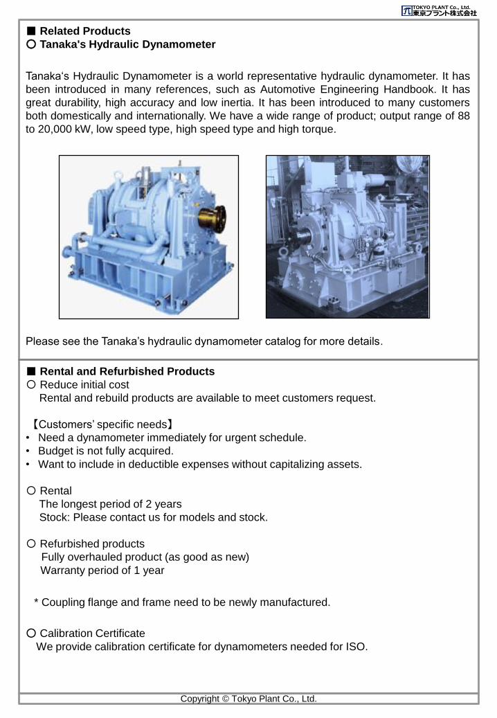
■ Related Products
○ Tanaka's Hydraulic Dynamometer
Tanaka‘s Hydraulic Dynamometer is a world representative hydraulic dynamometer. It has
been introduced in many references, such as Automotive Engineering Handbook. It has
great durability, high accuracy and low inertia. It has been introduced to many customers
both domestically and internationally. We have a wide range of product; output range of 88
to 20,000 kW, low speed type, high speed type and high torque.
Please see the Tanaka’s hydraulic dynamometer catalog for more details.
■ Rental and Refurbished Products
〇 Reduce initial cost
Rental and rebuild products are available to meet customers request.
【Customers’ specific needs】• Need a dynamometer immediately for urgent schedule.
• Budget is not fully acquired.
• Want to include in deductible expenses without capitalizing assets.
〇 Rental
The longest period of 2 years
Stock: Please contact us for models and stock.
〇 Refurbished products
Fully overhauled product (as good as new)
Warranty period of 1 year
* Coupling flange and frame need to be newly manufactured.
○ Calibration Certificate
We provide calibration certificate for dynamometers needed for ISO.
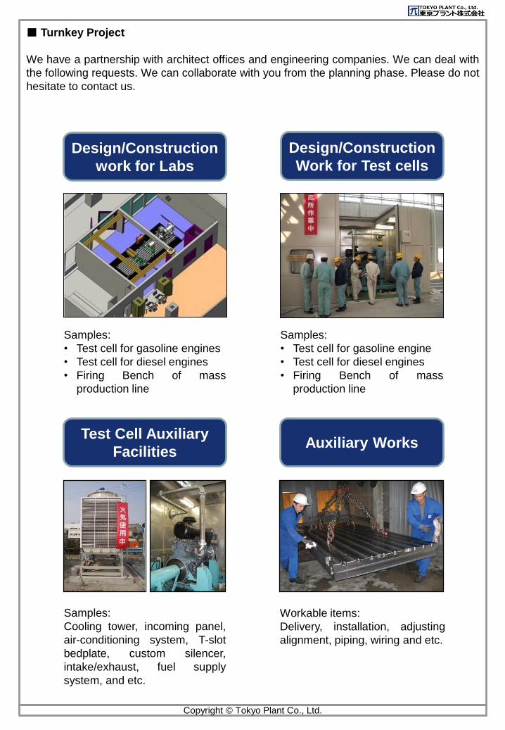
■ Turnkey Project
We have a partnership with architect offices and engineering companies. We can deal with
the following requests. We can collaborate with you from the planning phase. Please do not
hesitate to contact us.
Design/Construction
work for Labs
Design/Construction
Work for Test cells
Test Cell Auxiliary
FacilitiesAuxiliary Works
Samples:
• Test cell for gasoline engine
• Test cell for diesel engines
• Firing Bench of mass
production line
Samples:
• Test cell for gasoline engines
• Test cell for diesel engines
• Firing Bench of mass
production line
Workable items:
Delivery, installation, adjusting
alignment, piping, wiring and etc.
Samples:
Cooling tower, incoming panel,
air-conditioning system, T-slot
bedplate, custom silencer,
intake/exhaust, fuel supply
system, and etc.
Copyright © Tokyo Plant Co., Ltd.
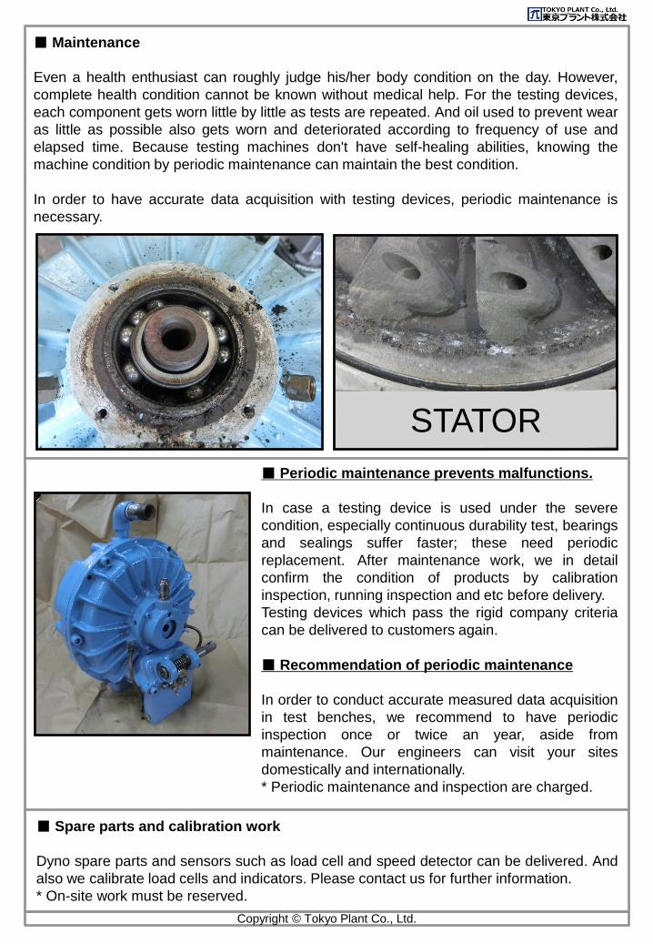
■ Maintenance
Even a health enthusiast can roughly judge his/her body condition on the day. However,
complete health condition cannot be known without medical help. For the testing devices,
each component gets worn little by little as tests are repeated. And oil used to prevent wear
as little as possible also gets worn and deteriorated according to frequency of use and
elapsed time. Because testing machines don't have self-healing abilities, knowing the
machine condition by periodic maintenance can maintain the best condition.
In order to have accurate data acquisition with testing devices, periodic maintenance is
necessary.
■ Periodic maintenance prevents malfunctions.
In case a testing device is used under the severe
condition, especially continuous durability test, bearings
and sealings suffer faster; these need periodic
replacement. After maintenance work, we in detail
confirm the condition of products by calibration
inspection, running inspection and etc before delivery.
Testing devices which pass the rigid company criteria
can be delivered to customers again.
■ Recommendation of periodic maintenance
In order to conduct accurate measured data acquisition
in test benches, we recommend to have periodic
inspection once or twice an year, aside from
maintenance. Our engineers can visit your sites
domestically and internationally.
* Periodic maintenance and inspection are charged.
■ Spare parts and calibration work
Dyno spare parts and sensors such as load cell and speed detector can be delivered. And
also we calibrate load cells and indicators. Please contact us for further information.
* On-site work must be reserved.
Copyright © Tokyo Plant Co., Ltd.
STATOR
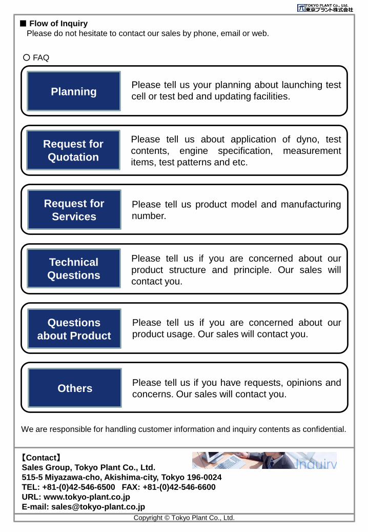
■ Flow of Inquiry
Please do not hesitate to contact our sales by phone, email or web.
【Contact】Sales Group, Tokyo Plant Co., Ltd.
515-5 Miyazawa-cho, Akishima-city, Tokyo 196-0024
TEL: +81-(0)42-546-6500 FAX: +81-(0)42-546-6600
URL: www.tokyo-plant.co.jp
E-mail: [email protected]
PlanningPlease tell us your planning about launching test
cell or test bed and updating facilities.
Request for
Quotation
Please tell us about application of dyno, test
contents, engine specification, measurement
items, test patterns and etc.
Technical
Questions
Please tell us if you are concerned about our
product structure and principle. Our sales will
contact you.
Request for
ServicesPlease tell us product model and manufacturing
number.
Questions
about Product
Please tell us if you are concerned about our
product usage. Our sales will contact you.
○ FAQ
OthersPlease tell us if you have requests, opinions and
concerns. Our sales will contact you.
We are responsible for handling customer information and inquiry contents as confidential.
Copyright © Tokyo Plant Co., Ltd.
Since 1948
Copyright © Tokyo Plant Co., Ltd.
Advanced Test System and Test Bed Engineering Professional