Embed Size (px)
Citation preview
GTX/GTX LTR/LTS 2000™Portable RadiosService Manual
68P02948C90-O
© 1997 by Motorola, Inc., Radio Products Group8000 W. Sunrise Blvd., Ft. Lauderdale, FL 33322Printed in U.S.A. 2/97 All Rights Reserved.
ForewordThe information contained in this manual relates to all GTX/GTX LTR/LTS 2000™ radios, unless otherwise specified.
Safety Information
Airbag Warning Statement
WARNING
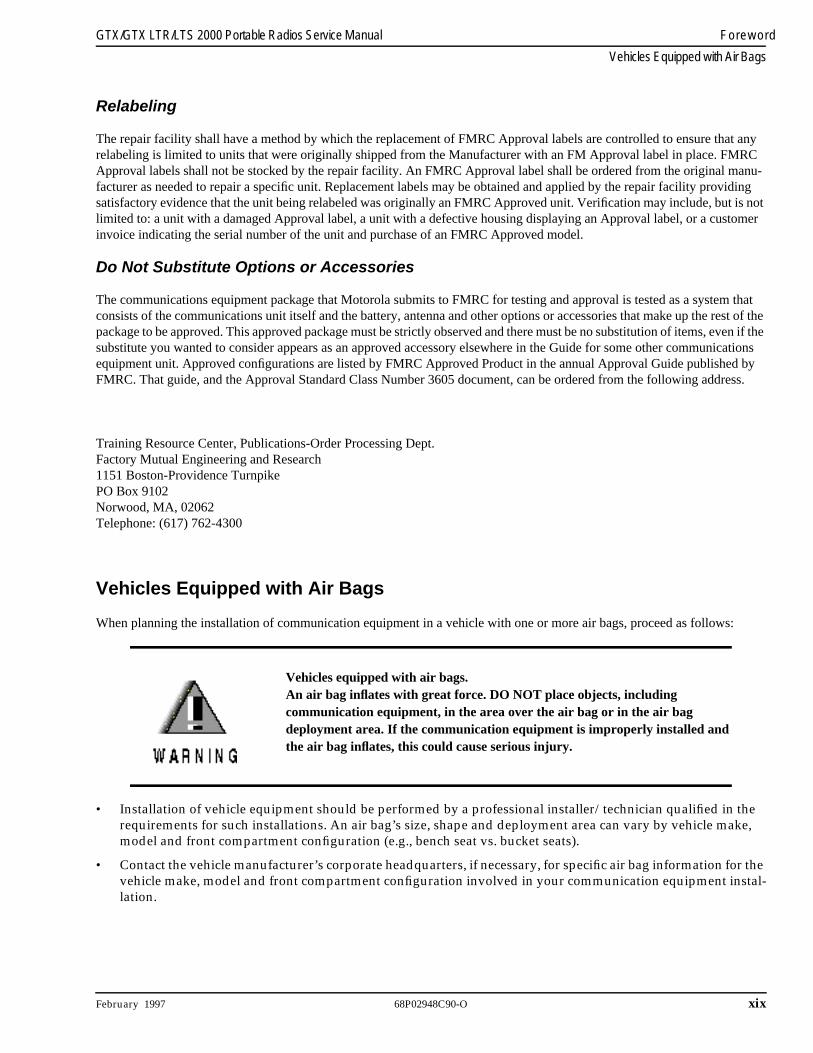
VEHICLES EQUIPPED WITH AIR BAGS
An air bag inflates with great force. DO NOT place objects, including communication equipment, in the area over the air bag or in the air bag deployment area. If the communication equipment is improperly installed and the air bag inflates, this could cause serious injury.
• Installation of vehicle communication equipment should be performed by a professional installer/technician qualified in the requirements for such installations. An air bag’s size, shape and deployment area can vary by vehicle make, model and front compartment configuration (e.g., bench seat vs. bucket seats).
• Contact the vehicle manufacturer’s corporate headquarters, if necessary, for specific air bag information for the vehi-cle make, model and front compartment configuration involved in your communication equipment installation.
FCC Safety Information
The Federal Communications Commission (FCC), with its action in General Docket 79-144, March 13, 1985, has adopted a safety standard for human exposure to radio frequency (RF) electromagnetic energy emitted by FCC-regulated equip-ment. Motorola subscribes to the same safety standard for the use of its products. Proper operation of this radio will result in user exposure substantially below FCC recommended limits.
• DO NOT hold the radio with the antenna very close to, or touching, exposed parts of the body, especially the face, ears, or eyes, while transmitting. Hold the radio in a vertical position with the microphone two to three inches away from the lips.
• DO NOT hold the transmit switch (PTT) on when not actually desiring to transmit.
• DO NOT allow children to play with any radio equipment containing a transmitter.
• DO NOT operate this equipment near electrical blasting caps or in an explosive atmosphere. Under certain condi-tions, radios can interfere with blasting operations. When you are in the vicinity of construction work, look for, and observe, signs cautioning against radio transmissions. If radio transmission is prohibited, you must not transmit until out of the area. Furthermore, you must turn off your radio to prevent any accidental transmission.
• DO NOT replace or charge batteries in a hazardous atmosphere. Contact sparking may occur while installing or removing batteries and cause an explosion.
• Turn the radio off when removing or installing a battery.
Anyone intending to use a radio in a hazardous area is advised to become familiar with the subject of intrinsic safety and with Section 70 of the National Fire Code, which is commonly referred to as Article 500 of the National Electric Code. Use of anything but factory supplied components may affect the approval and safety of the radio. Likewise, it is advised that servicing should be performed only by qualified personnel who adhere to the following Factory Mutual (FM) required warning:
WARNING
Modification of FM approved intrinsically safe radios will negate Factory Mutual Research Corporation (FMRC) approval.
Manual Revisions
Changes which occur after this manual is printed are described in “FMRs.” These FMRs provide complete information on changes including pertinent parts listing data.
Computer Software CopyrightsThe Motorola products described in this manual may include copyrighted Motorola computer programs stored in semiconductor memo-ries or other media. Laws in the United States and other countries preserve for Motorola certain exclusive rights for copyrighted computer programs, including the exclusive right to copy or reproduce in any form the copyrighted computer program. Accordingly, any copy-righted Motorola computer programs contained in the Motorola products described in this manual may not be copied or reproduced in any manner without the express written permission of Motorola. Furthermore, the purchase of Motorola products shall not be deemed to grant either directly or by implication, estoppel, or otherwise, any license under the copyrights, patents or patent applications of Motor-ola, except for the normal non-exclusive royalty free license to use that arises by operation of law in the sale of a product.
©Motorola Inc., 1997 All Rights Reserved 68P02948C90-O i
Table of Contents
Foreword . . . . . . . . . . . . . . . . . . . . . . . . . . . . . . . . . . . . . . . . . . . . . . . . . . . . . . . . . . . . . . . . . . . . . . . . . . . Inside front coverGTX and GTX LTR Portable Radios Model Chart . . . . . . . . . . . . . . . . . . . . . . . . . . . . . . . . . . . . . . . . . . . . . . . . . . vLTS 2000 Portable Radio Model Chart. . . . . . . . . . . . . . . . . . . . . . . . . . . . . . . . . . . . . . . . . . . . . . . . . . . . . . . . . . . . vi GTX/GTX LTR/LTS 2000 Options. . . . . . . . . . . . . . . . . . . . . . . . . . . . . . . . . . . . . . . . . . . . . . . . . . . . . . . . . . . . . . . viiGTX/GTX LTR/LTS 2000 Accessories . . . . . . . . . . . . . . . . . . . . . . . . . . . . . . . . . . . . . . . . . . . . . . . . . . . . . . . . . . . viiiPerformance Specifications: GTX/GTX LTR/LTS 2000 . . . . . . . . . . . . . . . . . . . . . . . . . . . . . . . . . . . . . . . . . . . . . xService Aids . . . . . . . . . . . . . . . . . . . . . . . . . . . . . . . . . . . . . . . . . . . . . . . . . . . . . . . . . . . . . . . . . . . . . . . . . . . . . . . . . . xiTest Equipment . . . . . . . . . . . . . . . . . . . . . . . . . . . . . . . . . . . . . . . . . . . . . . . . . . . . . . . . . . . . . . . . . . . . . . . . . . . . . . . xiService Tools . . . . . . . . . . . . . . . . . . . . . . . . . . . . . . . . . . . . . . . . . . . . . . . . . . . . . . . . . . . . . . . . . . . . . . . . . . . . . . . . . xii
Test Set Service Cable . . . . . . . . . . . . . . . . . . . . . . . . . . . . . . . . . . . . . . . . . . . . . . . . . . . . . . . . . . . . . . . . . . . . . . xiiiRadio Model Numbering System. . . . . . . . . . . . . . . . . . . . . . . . . . . . . . . . . . . . . . . . . . . . . . . . . . . . . . . . . . . . . . . . xivRadio Service Software Information. . . . . . . . . . . . . . . . . . . . . . . . . . . . . . . . . . . . . . . . . . . . . . . . . . . . . . . . . . . . . . xvConfiguring the RIB and Radio. . . . . . . . . . . . . . . . . . . . . . . . . . . . . . . . . . . . . . . . . . . . . . . . . . . . . . . . . . . . . . . . . . xviImportant Safety Information: Intrinsically Safe Radios. . . . . . . . . . . . . . . . . . . . . . . . . . . . . . . . . . . . . . . . . . . . . xvii
FMRC Approved Equipment . . . . . . . . . . . . . . . . . . . . . . . . . . . . . . . . . . . . . . . . . . . . . . . . . . . . . . . . . . . . . . . xviiRepair of FMRC Approved Products . . . . . . . . . . . . . . . . . . . . . . . . . . . . . . . . . . . . . . . . . . . . . . . . . . . . . . . . . xviiiRepair . . . . . . . . . . . . . . . . . . . . . . . . . . . . . . . . . . . . . . . . . . . . . . . . . . . . . . . . . . . . . . . . . . . . . . . . . . . . . . . . . . . xviiiRelabeling . . . . . . . . . . . . . . . . . . . . . . . . . . . . . . . . . . . . . . . . . . . . . . . . . . . . . . . . . . . . . . . . . . . . . . . . . . . . . . . . xixDo Not Substitute Options or Accessories . . . . . . . . . . . . . . . . . . . . . . . . . . . . . . . . . . . . . . . . . . . . . . . . . . . . xix
Vehicles Equipped with Air Bags . . . . . . . . . . . . . . . . . . . . . . . . . . . . . . . . . . . . . . . . . . . . . . . . . . . . . . . . . . . . . . . xix
Section 1Radio Disassembly/AssemblyOverview . . . . . . . . . . . . . . . . . . . . . . . . . . . . . . . . . . . . . . . . . . . . . . . . . . . . . . . . . . . . . . . . . . . . . . . . . . . . . . . . . . . . 1-1Safety Information. . . . . . . . . . . . . . . . . . . . . . . . . . . . . . . . . . . . . . . . . . . . . . . . . . . . . . . . . . . . . . . . . . . . . . . . . . . . . 1-1Radio Disassembly . . . . . . . . . . . . . . . . . . . . . . . . . . . . . . . . . . . . . . . . . . . . . . . . . . . . . . . . . . . . . . . . . . . . . . . . . . . . 1-1
Battery Removal. . . . . . . . . . . . . . . . . . . . . . . . . . . . . . . . . . . . . . . . . . . . . . . . . . . . . . . . . . . . . . . . . . . . . . . . . . . 1-1Chassis Removal. . . . . . . . . . . . . . . . . . . . . . . . . . . . . . . . . . . . . . . . . . . . . . . . . . . . . . . . . . . . . . . . . . . . . . . . . . . 1-1Main Board Removal. . . . . . . . . . . . . . . . . . . . . . . . . . . . . . . . . . . . . . . . . . . . . . . . . . . . . . . . . . . . . . . . . . . . . . . 1-2Front Housing Board Removal . . . . . . . . . . . . . . . . . . . . . . . . . . . . . . . . . . . . . . . . . . . . . . . . . . . . . . . . . . . . . . 1-3
Radio Reassembly. . . . . . . . . . . . . . . . . . . . . . . . . . . . . . . . . . . . . . . . . . . . . . . . . . . . . . . . . . . . . . . . . . . . . . . . . . . . . 1-3Front Housing Reassembly. . . . . . . . . . . . . . . . . . . . . . . . . . . . . . . . . . . . . . . . . . . . . . . . . . . . . . . . . . . . . . . . . . 1-3Chassis Reassembly. . . . . . . . . . . . . . . . . . . . . . . . . . . . . . . . . . . . . . . . . . . . . . . . . . . . . . . . . . . . . . . . . . . . . . . . 1-4Radio Reassembly . . . . . . . . . . . . . . . . . . . . . . . . . . . . . . . . . . . . . . . . . . . . . . . . . . . . . . . . . . . . . . . . . . . . . . . . . 1-5
Section 2Theory of OperationOverview . . . . . . . . . . . . . . . . . . . . . . . . . . . . . . . . . . . . . . . . . . . . . . . . . . . . . . . . . . . . . . . . . . . . . . . . . . . . . . . . . . . . 2-1Receiver . . . . . . . . . . . . . . . . . . . . . . . . . . . . . . . . . . . . . . . . . . . . . . . . . . . . . . . . . . . . . . . . . . . . . . . . . . . . . . . . . . . . . 2-1
Intermediate Frequency (IF) . . . . . . . . . . . . . . . . . . . . . . . . . . . . . . . . . . . . . . . . . . . . . . . . . . . . . . . . . . . . . . . . 2-1Transmitter . . . . . . . . . . . . . . . . . . . . . . . . . . . . . . . . . . . . . . . . . . . . . . . . . . . . . . . . . . . . . . . . . . . . . . . . . . . . . . . . . . 2-1Frequency Generation Unit . . . . . . . . . . . . . . . . . . . . . . . . . . . . . . . . . . . . . . . . . . . . . . . . . . . . . . . . . . . . . . . . . . . . 2-4Controller . . . . . . . . . . . . . . . . . . . . . . . . . . . . . . . . . . . . . . . . . . . . . . . . . . . . . . . . . . . . . . . . . . . . . . . . . . . . . . . . . . . 2-5
Functions . . . . . . . . . . . . . . . . . . . . . . . . . . . . . . . . . . . . . . . . . . . . . . . . . . . . . . . . . . . . . . . . . . . . . . . . . . . . . . . . 2-5Normal Operation . . . . . . . . . . . . . . . . . . . . . . . . . . . . . . . . . . . . . . . . . . . . . . . . . . . . . . . . . . . . . . . . . . . . . . . . . 2-5Clock Synthesizer . . . . . . . . . . . . . . . . . . . . . . . . . . . . . . . . . . . . . . . . . . . . . . . . . . . . . . . . . . . . . . . . . . . . . . . . . 2-5
ii 68P02948C90-O February 1997
Table of Contents GTX/GTX LTR/LTS 2000 Portable Radios Service Manual
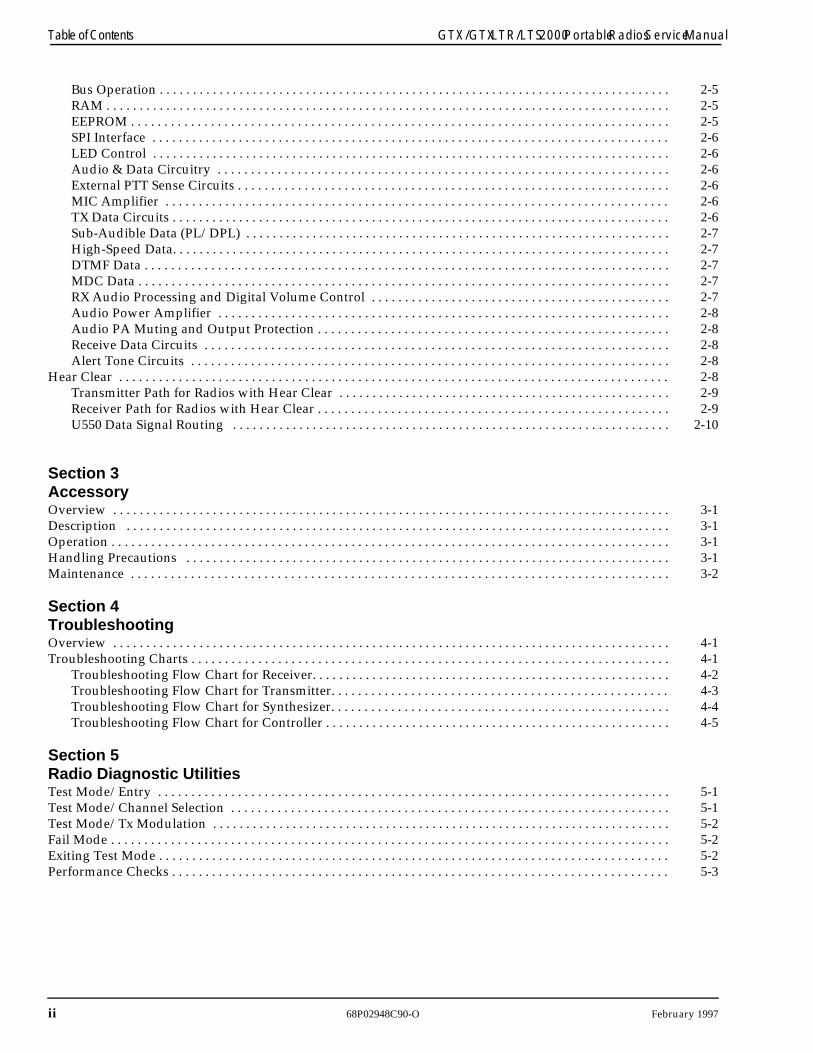
Bus Operation . . . . . . . . . . . . . . . . . . . . . . . . . . . . . . . . . . . . . . . . . . . . . . . . . . . . . . . . . . . . . . . . . . . . . . . . . . . . . 2-5RAM . . . . . . . . . . . . . . . . . . . . . . . . . . . . . . . . . . . . . . . . . . . . . . . . . . . . . . . . . . . . . . . . . . . . . . . . . . . . . . . . . . . . . 2-5EEPROM . . . . . . . . . . . . . . . . . . . . . . . . . . . . . . . . . . . . . . . . . . . . . . . . . . . . . . . . . . . . . . . . . . . . . . . . . . . . . . . . . 2-5SPI Interface . . . . . . . . . . . . . . . . . . . . . . . . . . . . . . . . . . . . . . . . . . . . . . . . . . . . . . . . . . . . . . . . . . . . . . . . . . . . . . 2-6LED Control . . . . . . . . . . . . . . . . . . . . . . . . . . . . . . . . . . . . . . . . . . . . . . . . . . . . . . . . . . . . . . . . . . . . . . . . . . . . . . 2-6Audio & Data Circuitry . . . . . . . . . . . . . . . . . . . . . . . . . . . . . . . . . . . . . . . . . . . . . . . . . . . . . . . . . . . . . . . . . . . . 2-6External PTT Sense Circuits . . . . . . . . . . . . . . . . . . . . . . . . . . . . . . . . . . . . . . . . . . . . . . . . . . . . . . . . . . . . . . . . . 2-6MIC Amplifier . . . . . . . . . . . . . . . . . . . . . . . . . . . . . . . . . . . . . . . . . . . . . . . . . . . . . . . . . . . . . . . . . . . . . . . . . . . . 2-6TX Data Circuits . . . . . . . . . . . . . . . . . . . . . . . . . . . . . . . . . . . . . . . . . . . . . . . . . . . . . . . . . . . . . . . . . . . . . . . . . . . 2-6Sub-Audible Data (PL/DPL) . . . . . . . . . . . . . . . . . . . . . . . . . . . . . . . . . . . . . . . . . . . . . . . . . . . . . . . . . . . . . . . . 2-7High-Speed Data. . . . . . . . . . . . . . . . . . . . . . . . . . . . . . . . . . . . . . . . . . . . . . . . . . . . . . . . . . . . . . . . . . . . . . . . . . . 2-7DTMF Data . . . . . . . . . . . . . . . . . . . . . . . . . . . . . . . . . . . . . . . . . . . . . . . . . . . . . . . . . . . . . . . . . . . . . . . . . . . . . . . 2-7MDC Data . . . . . . . . . . . . . . . . . . . . . . . . . . . . . . . . . . . . . . . . . . . . . . . . . . . . . . . . . . . . . . . . . . . . . . . . . . . . . . . . 2-7RX Audio Processing and Digital Volume Control . . . . . . . . . . . . . . . . . . . . . . . . . . . . . . . . . . . . . . . . . . . . . 2-7Audio Power Amplifier . . . . . . . . . . . . . . . . . . . . . . . . . . . . . . . . . . . . . . . . . . . . . . . . . . . . . . . . . . . . . . . . . . . . 2-8Audio PA Muting and Output Protection . . . . . . . . . . . . . . . . . . . . . . . . . . . . . . . . . . . . . . . . . . . . . . . . . . . . . 2-8Receive Data Circuits . . . . . . . . . . . . . . . . . . . . . . . . . . . . . . . . . . . . . . . . . . . . . . . . . . . . . . . . . . . . . . . . . . . . . . 2-8Alert Tone Circuits . . . . . . . . . . . . . . . . . . . . . . . . . . . . . . . . . . . . . . . . . . . . . . . . . . . . . . . . . . . . . . . . . . . . . . . . 2-8
Hear Clear . . . . . . . . . . . . . . . . . . . . . . . . . . . . . . . . . . . . . . . . . . . . . . . . . . . . . . . . . . . . . . . . . . . . . . . . . . . . . . . . . . . 2-8Transmitter Path for Radios with Hear Clear . . . . . . . . . . . . . . . . . . . . . . . . . . . . . . . . . . . . . . . . . . . . . . . . . . 2-9Receiver Path for Radios with Hear Clear . . . . . . . . . . . . . . . . . . . . . . . . . . . . . . . . . . . . . . . . . . . . . . . . . . . . . 2-9U550 Data Signal Routing . . . . . . . . . . . . . . . . . . . . . . . . . . . . . . . . . . . . . . . . . . . . . . . . . . . . . . . . . . . . . . . . . . 2-10
Section 3AccessoryOverview . . . . . . . . . . . . . . . . . . . . . . . . . . . . . . . . . . . . . . . . . . . . . . . . . . . . . . . . . . . . . . . . . . . . . . . . . . . . . . . . . . . . 3-1Description . . . . . . . . . . . . . . . . . . . . . . . . . . . . . . . . . . . . . . . . . . . . . . . . . . . . . . . . . . . . . . . . . . . . . . . . . . . . . . . . . . 3-1Operation . . . . . . . . . . . . . . . . . . . . . . . . . . . . . . . . . . . . . . . . . . . . . . . . . . . . . . . . . . . . . . . . . . . . . . . . . . . . . . . . . . . . 3-1Handling Precautions . . . . . . . . . . . . . . . . . . . . . . . . . . . . . . . . . . . . . . . . . . . . . . . . . . . . . . . . . . . . . . . . . . . . . . . . . 3-1Maintenance . . . . . . . . . . . . . . . . . . . . . . . . . . . . . . . . . . . . . . . . . . . . . . . . . . . . . . . . . . . . . . . . . . . . . . . . . . . . . . . . . 3-2
Section 4TroubleshootingOverview . . . . . . . . . . . . . . . . . . . . . . . . . . . . . . . . . . . . . . . . . . . . . . . . . . . . . . . . . . . . . . . . . . . . . . . . . . . . . . . . . . . . 4-1Troubleshooting Charts . . . . . . . . . . . . . . . . . . . . . . . . . . . . . . . . . . . . . . . . . . . . . . . . . . . . . . . . . . . . . . . . . . . . . . . . 4-1
Troubleshooting Flow Chart for Receiver. . . . . . . . . . . . . . . . . . . . . . . . . . . . . . . . . . . . . . . . . . . . . . . . . . . . . . 4-2Troubleshooting Flow Chart for Transmitter. . . . . . . . . . . . . . . . . . . . . . . . . . . . . . . . . . . . . . . . . . . . . . . . . . . 4-3Troubleshooting Flow Chart for Synthesizer. . . . . . . . . . . . . . . . . . . . . . . . . . . . . . . . . . . . . . . . . . . . . . . . . . . 4-4Troubleshooting Flow Chart for Controller . . . . . . . . . . . . . . . . . . . . . . . . . . . . . . . . . . . . . . . . . . . . . . . . . . . . 4-5
Section 5Radio Diagnostic UtilitiesTest Mode/Entry . . . . . . . . . . . . . . . . . . . . . . . . . . . . . . . . . . . . . . . . . . . . . . . . . . . . . . . . . . . . . . . . . . . . . . . . . . . . . 5-1Test Mode/Channel Selection . . . . . . . . . . . . . . . . . . . . . . . . . . . . . . . . . . . . . . . . . . . . . . . . . . . . . . . . . . . . . . . . . . 5-1Test Mode/Tx Modulation . . . . . . . . . . . . . . . . . . . . . . . . . . . . . . . . . . . . . . . . . . . . . . . . . . . . . . . . . . . . . . . . . . . . . 5-2Fail Mode . . . . . . . . . . . . . . . . . . . . . . . . . . . . . . . . . . . . . . . . . . . . . . . . . . . . . . . . . . . . . . . . . . . . . . . . . . . . . . . . . . . . 5-2Exiting Test Mode . . . . . . . . . . . . . . . . . . . . . . . . . . . . . . . . . . . . . . . . . . . . . . . . . . . . . . . . . . . . . . . . . . . . . . . . . . . . . 5-2Performance Checks . . . . . . . . . . . . . . . . . . . . . . . . . . . . . . . . . . . . . . . . . . . . . . . . . . . . . . . . . . . . . . . . . . . . . . . . . . . 5-3
February 1997 68P02948C90-O iii
GTX/GTX LTR/LTS 2000 Portable Radios Service Manual Table of Contents
Section 6MaintenanceIntroduction . . . . . . . . . . . . . . . . . . . . . . . . . . . . . . . . . . . . . . . . . . . . . . . . . . . . . . . . . . . . . . . . . . . . . . . . . . . . . . . . . . 6-1Preventive Maintenance. . . . . . . . . . . . . . . . . . . . . . . . . . . . . . . . . . . . . . . . . . . . . . . . . . . . . . . . . . . . . . . . . . . . . . . . 6-1
Inspection . . . . . . . . . . . . . . . . . . . . . . . . . . . . . . . . . . . . . . . . . . . . . . . . . . . . . . . . . . . . . . . . . . . . . . . . . . . . . . . . 6-1Cleaning . . . . . . . . . . . . . . . . . . . . . . . . . . . . . . . . . . . . . . . . . . . . . . . . . . . . . . . . . . . . . . . . . . . . . . . . . . . . . . . . . 6-1
Cleaning External Plastic Surfaces . . . . . . . . . . . . . . . . . . . . . . . . . . . . . . . . . . . . . . . . . . . . . . . . . . . . . . . . 6-1Cleaning Internal Circuit Boards and Components . . . . . . . . . . . . . . . . . . . . . . . . . . . . . . . . . . . . . . . . . 6-1
Safe Handling of CMOS Devices . . . . . . . . . . . . . . . . . . . . . . . . . . . . . . . . . . . . . . . . . . . . . . . . . . . . . . . . . . . . . . . . 6-1Repair Procedures and Techniques . . . . . . . . . . . . . . . . . . . . . . . . . . . . . . . . . . . . . . . . . . . . . . . . . . . . . . . . . . . . . . 6-2
General . . . . . . . . . . . . . . . . . . . . . . . . . . . . . . . . . . . . . . . . . . . . . . . . . . . . . . . . . . . . . . . . . . . . . . . . . . . . . . . . . . 6-2Parts Replacement and Substitution . . . . . . . . . . . . . . . . . . . . . . . . . . . . . . . . . . . . . . . . . . . . . . . . . . . . . . 6-2Rigid Circuit Boards . . . . . . . . . . . . . . . . . . . . . . . . . . . . . . . . . . . . . . . . . . . . . . . . . . . . . . . . . . . . . . . . . . . . 6-2Chip Components . . . . . . . . . . . . . . . . . . . . . . . . . . . . . . . . . . . . . . . . . . . . . . . . . . . . . . . . . . . . . . . . . . . . . 6-2Over-Molded Pad-Array Carrier (OMPAC) . . . . . . . . . . . . . . . . . . . . . . . . . . . . . . . . . . . . . . . . . . . . . . . 6-2Shields . . . . . . . . . . . . . . . . . . . . . . . . . . . . . . . . . . . . . . . . . . . . . . . . . . . . . . . . . . . . . . . . . . . . . . . . . . . . . . . 6-3
Section 7Radio Tuning ProcedureRadio Tuning Procedure . . . . . . . . . . . . . . . . . . . . . . . . . . . . . . . . . . . . . . . . . . . . . . . . . . . . . . . . . . . . . . . . . . . . . . . 7-1
General . . . . . . . . . . . . . . . . . . . . . . . . . . . . . . . . . . . . . . . . . . . . . . . . . . . . . . . . . . . . . . . . . . . . . . . . . . . . . . . . . . 7-1Tuning Procedure . . . . . . . . . . . . . . . . . . . . . . . . . . . . . . . . . . . . . . . . . . . . . . . . . . . . . . . . . . . . . . . . . . . . . . . . . . . . . 7-2
Reference Oscillator Alignment . . . . . . . . . . . . . . . . . . . . . . . . . . . . . . . . . . . . . . . . . . . . . . . . . . . . . . . . . . . . . 7-2Squelch . . . . . . . . . . . . . . . . . . . . . . . . . . . . . . . . . . . . . . . . . . . . . . . . . . . . . . . . . . . . . . . . . . . . . . . . . . . . . . . . . . 7-3Transmitter Power . . . . . . . . . . . . . . . . . . . . . . . . . . . . . . . . . . . . . . . . . . . . . . . . . . . . . . . . . . . . . . . . . . . . . . . . 7-3Transmit Deviation Balance (Compensation) & Deviation Limit . . . . . . . . . . . . . . . . . . . . . . . . . . . . . . . . . 7-3Transmit Deviation Limit . . . . . . . . . . . . . . . . . . . . . . . . . . . . . . . . . . . . . . . . . . . . . . . . . . . . . . . . . . . . . . . . . . . 7-3
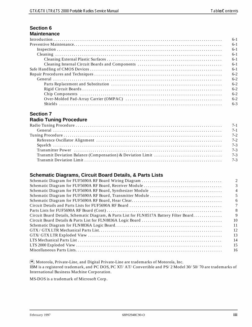
Schematic Diagrams, Circuit Board Details, & Parts ListsSchematic Diagram for FUF5690A RF Board Wiring Diagram . . . . . . . . . . . . . . . . . . . . . . . . . . . . . . . . . . . . . . . 2Schematic Diagram for FUF5690A RF Board, Receiver Module . . . . . . . . . . . . . . . . . . . . . . . . . . . . . . . . . . . . . . 3Schematic Diagram for FUF5690A RF Board, Synthesizer Module . . . . . . . . . . . . . . . . . . . . . . . . . . . . . . . . . . . 4Schematic Diagram for FUF5690A RF Board, Transmitter Module . . . . . . . . . . . . . . . . . . . . . . . . . . . . . . . . . . . 5Schematic Diagram for FUF5690A RF Board, Hear Clear. . . . . . . . . . . . . . . . . . . . . . . . . . . . . . . . . . . . . . . . . . . . 6Circuit Details and Parts Lists for FUF5690A RF Board . . . . . . . . . . . . . . . . . . . . . . . . . . . . . . . . . . . . . . . . . . . . . 7Parts Lists for FUF5690A RF Board (Cont) . . . . . . . . . . . . . . . . . . . . . . . . . . . . . . . . . . . . . . . . . . . . . . . . . . . . . . . . 8Circuit Board Details, Schematic Diagram, & Parts List for FLN8517A Battery Filter Board. . . . . . . . . . . . . . 9Circuit Board Details & Parts List for FLN8836A Logic Board . . . . . . . . . . . . . . . . . . . . . . . . . . . . . . . . . . . . . . . 10Schematic Diagram for FLN8836A Logic Board. . . . . . . . . . . . . . . . . . . . . . . . . . . . . . . . . . . . . . . . . . . . . . . . . . . . 11GTX /GTX LTR Mechanical Parts List. . . . . . . . . . . . . . . . . . . . . . . . . . . . . . . . . . . . . . . . . . . . . . . . . . . . . . . . . . . . 12GTX/GTX LTR Exploded View . . . . . . . . . . . . . . . . . . . . . . . . . . . . . . . . . . . . . . . . . . . . . . . . . . . . . . . . . . . . . . . . . 13LTS Mechanical Parts List . . . . . . . . . . . . . . . . . . . . . . . . . . . . . . . . . . . . . . . . . . . . . . . . . . . . . . . . . . . . . . . . . . . . . . 14LTS 2000 Exploded View . . . . . . . . . . . . . . . . . . . . . . . . . . . . . . . . . . . . . . . . . . . . . . . . . . . . . . . . . . . . . . . . . . . . . . . 15Miscellaneous Parts Lists. . . . . . . . . . . . . . . . . . . . . . . . . . . . . . . . . . . . . . . . . . . . . . . . . . . . . . . . . . . . . . . . . . . . . . . 16
, Motorola, Private-Line, and Digital Private-Line are trademarks of Motorola, Inc.IBM is a registered trademark, and PC DOS, PC XT/AT/Convertible and PS/2 Model 30/50/70 are trademarks of International Business Machine Corporation.
MS-DOS is a trademark of Microsoft Corp.

iv 68P02948C90-O February 1997
Table of Contents GTX/GTX LTR/LTS 2000 Portable Radios Service Manual
This page intentionally left blank
February 1997 68P02948C90-O
v
GTX/GTX LTR/LTS 2000 Portable Radios Service Manual Foreword
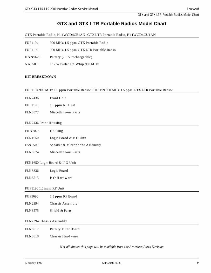
GTX and GTX LTR Portable Radios Model Chart
GTX and GTX LTR Portable Radios Model Chart
GTX Portable Radio, H11WCD4CB1AN: GTX LTR Portable Radio, H11WCD4CU1AN
FUF1194 900 MHz 1.5 ppm GTX Portable Radio
FUF1199 900 MHz 1.5 ppm GTX LTR Portable Radio
HNN9628 Battery (7.5 V rechargeable)
NAF5038 1/2 Wavelength Whip 900 MHz
KIT BREAKDOWN
FUF1194 900 MHz 1.5 ppm Portable Radio: FUF1199 900 MHz 1.5 ppm GTX LTR Portable Radio:
FLN2436 Front Unit
FUF1196 1.5 ppm RF Unit
FLN8577 Miscellaneous Parts
FLN2436 Front Housing
FHN5873 Housing
FEN1650 Logic Board & I/O Unit
FSN5509 Speaker & Microphone Assembly
FLN8574 Miscellaneous Parts
FEN1650 Logic Board & I/O Unit
FLN8836 Logic Board
FLN8515 I/O Hardware
FUF1196 1.5 ppm RF Unit
FUF5690 1.5 ppm RF Board
FLN2394 Chassis Assembly
FLN8575 Shield & Parts
FLN2394 Chassis Assembly
FLN8517 Battery Filter Board
FLN8518 Chassis Hardware
Not all kits on this page will be available from the Americas Parts Division
vi
68P02948C90-O February 1997
Foreword GTX/GTX LTR/LTS 2000 Portable Radios Service Manual
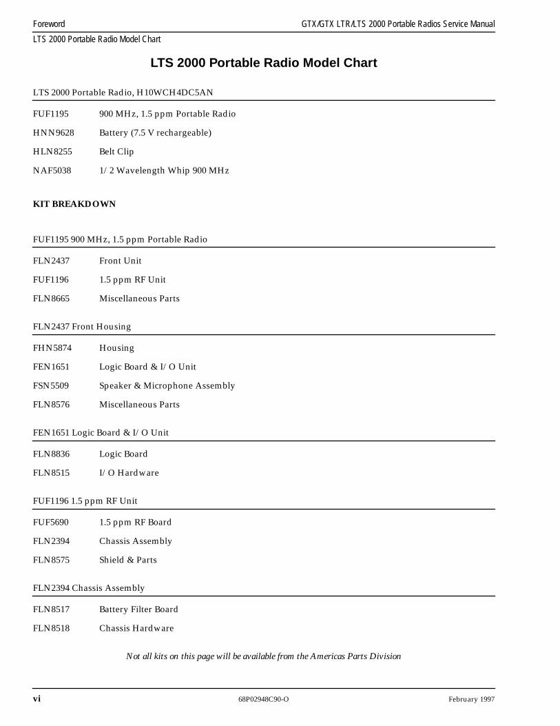
LTS 2000 Portable Radio Model Chart
LTS 2000 Portable Radio Model Chart
LTS 2000 Portable Radio, H10WCH4DC5AN
FUF1195 900 MHz, 1.5 ppm Portable Radio
HNN9628 Battery (7.5 V rechargeable)
HLN8255 Belt Clip
NAF5038 1/2 Wavelength Whip 900 MHz
KIT BREAKDOWN
FUF1195 900 MHz, 1.5 ppm Portable Radio
FLN2437 Front Unit
FUF1196 1.5 ppm RF Unit
FLN8665 Miscellaneous Parts
FLN2437 Front Housing
FHN5874 Housing
FEN1651 Logic Board & I/O Unit
FSN5509 Speaker & Microphone Assembly
FLN8576 Miscellaneous Parts
FEN1651 Logic Board & I/O Unit
FLN8836 Logic Board
FLN8515 I/O Hardware
FUF1196 1.5 ppm RF Unit
FUF5690 1.5 ppm RF Board
FLN2394 Chassis Assembly
FLN8575 Shield & Parts
FLN2394 Chassis Assembly
FLN8517 Battery Filter Board
FLN8518 Chassis Hardware
Not all kits on this page will be available from the Americas Parts Division
February 1997 68P02948C90-O
vii
GTX/GTX LTR/LTS 2000 Portable Radios Service Manual Foreword
GTX/GTX LTR/LTS 2000 Options
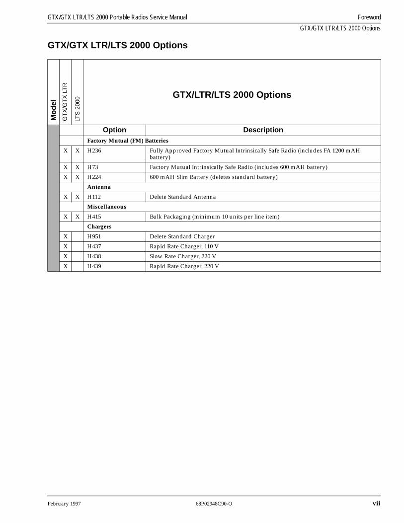
GTX/GTX LTR/LTS 2000 Options
GTX/LTR/LTS 2000 Options
Option Description
Factory Mutual (FM) Batteries
X X H236 Fully Approved Factory Mutual Intrinsically Safe Radio (includes FA 1200 mAHbattery)
X X H73 Factory Mutual Intrinsically Safe Radio (includes 600 mAH battery)
X X H224 600 mAH Slim Battery (deletes standard battery)
Antenna
X X H112 Delete Standard Antenna
Miscellaneous
X X H415 Bulk Packaging (minimum 10 units per line item)
Chargers
X H951 Delete Standard Charger
X H437 Rapid Rate Charger, 110 V
X H438 Slow Rate Charger, 220 V
X H439 Rapid Rate Charger, 220 V
Mod
el
GT
X/G
TX
LT
R
LTS
200
0
viii
68P02948C90-O February 1997
Foreword GTX/GTX LTR/LTS 2000 Portable Radios Service Manual
GTX/GTX LTR/LTS 2000 Accessories
GTX/GTX LTR/LTS 2000 Accessories
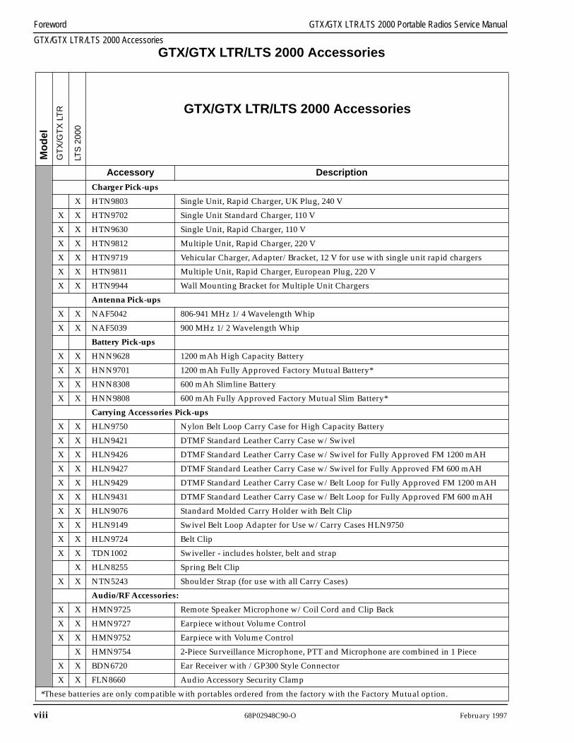
GTX/GTX LTR/LTS 2000 Accessories
Accessory Description
Charger Pick-ups
X HTN9803 Single Unit, Rapid Charger, UK Plug, 240 V
X X HTN9702 Single Unit Standard Charger, 110 V
X X HTN9630 Single Unit, Rapid Charger, 110 V
X X HTN9812 Multiple Unit, Rapid Charger, 220 V
X X HTN9719 Vehicular Charger, Adapter/Bracket, 12 V for use with single unit rapid chargers
X X HTN9811 Multiple Unit, Rapid Charger, European Plug, 220 V
X X HTN9944 Wall Mounting Bracket for Multiple Unit Chargers
Antenna Pick-ups
X X NAF5042 806-941 MHz 1/4 Wavelength Whip
X X NAF5039 900 MHz 1/2 Wavelength Whip
Battery Pick-ups
X X HNN9628 1200 mAh High Capacity Battery
X X HNN9701 1200 mAh Fully Approved Factory Mutual Battery*
X X HNN8308 600 mAh Slimline Battery
X X HNN9808 600 mAh Fully Approved Factory Mutual Slim Battery*
Carrying Accessories Pick-ups
X X HLN9750 Nylon Belt Loop Carry Case for High Capacity Battery
X X HLN9421 DTMF Standard Leather Carry Case w/Swivel
X X HLN9426 DTMF Standard Leather Carry Case w/Swivel for Fully Approved FM 1200 mAH
X X HLN9427 DTMF Standard Leather Carry Case w/Swivel for Fully Approved FM 600 mAH
X X HLN9429 DTMF Standard Leather Carry Case w/Belt Loop for Fully Approved FM 1200 mAH
X X HLN9431 DTMF Standard Leather Carry Case w/Belt Loop for Fully Approved FM 600 mAH
X X HLN9076 Standard Molded Carry Holder with Belt Clip
X X HLN9149 Swivel Belt Loop Adapter for Use w/Carry Cases HLN9750
X X HLN9724 Belt Clip
X X TDN1002 Swiveller - includes holster, belt and strap
X HLN8255 Spring Belt Clip
X X NTN5243 Shoulder Strap (for use with all Carry Cases)
Audio/RF Accessories:
X X HMN9725 Remote Speaker Microphone w/Coil Cord and Clip Back
X X HMN9727 Earpiece without Volume Control
X X HMN9752 Earpiece with Volume Control
X HMN9754 2-Piece Surveillance Microphone, PTT and Microphone are combined in 1 Piece
X X BDN6720 Ear Receiver with /GP300 Style Connector
X X FLN8660 Audio Accessory Security Clamp
*These batteries are only compatible with portables ordered from the factory with the Factory Mutual option.
Mod
el
GT
X/G
TX
LT
R
LTS
200
0
February 1997 68P02948C90-O
ix
GTX/GTX LTR/LTS 2000 Portable Radios Service Manual Foreword
GTX/GTX LTR/LTS 2000 Accessories
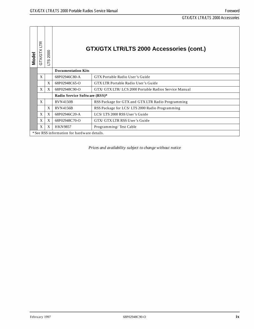
Prices and availability subject to change without notice
GTX/GTX LTR/LTS 2000 Accessories (cont.)
Documentation Kits
X 68P02946C80-A GTX Portable Radio User’s Guide
X 68P02948C65-O GTX LTR Portable Radio User’s Guide
X X 68P02948C90-O GTX/GTX LTR/LCS 2000 Portable Radios Service Manual
Radio Service Software (RSS)*
X RVN4150B RSS Package for GTX and GTX LTR Radio Programming
X RVN4156B RSS Package for LCS/LTS 2000 Radio Programming
X X 68P02946C20-A LCS/LTS 2000 RSS User’s Guide
X X 68P02948C70-O GTX/GTX LTR RSS User’s Guide
X X HKN9857 Programming/Test Cable
* See RSS information for hardware details.
Mod
el
GT
X/G
TX
LT
R
LTS
200
0
x
68P02948C90-O February 1997
Foreword GTX/GTX LTR/LTS 2000 Portable Radios Service Manual
Performance Specifications: GTX/GTX LTR/LTS 2000
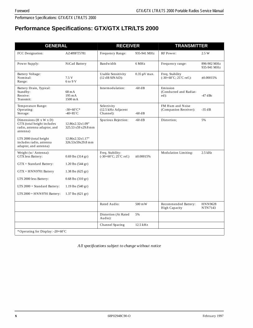
Performance Specifications: GTX/GTX LTR/LTS 2000
All specifications subject to change without notice
GENERAL RECEIVER TRANSMITTER
FCC Designation: AZ489FT5781 Frequency Range: 935-941 MHz RF Power: 2.5 W
Power Supply: NiCad Battery Bandwidth 6 MHz Frequency range: 896-902 MHz935-941 MHz
Battery Voltage: Nominal:Range:
7.5 V6 to 9 V
Usable Sensitivity(12 dB SINAD):
0.35
µ
V max. Freq. Stability(-30+60˚C; 25˚C ref.):
±
0.00015%
Battery Drain, Typical:Standby:Receive:Transmit:
68 mA195 mA1500 mA
Intermodulation: -60 dB Emission (Conducted and Radiat-ed): -47 dBc
Temperature Range:Operating:Storage:
-30+60˚C*-40+85˚C
Selectivity(12.5 kHz Adjacent Channel): -60 dB
FM Hum and Noise(Companion Receiver): -35 dB
Dimensions (H x W x D)GTX (total height includesradio, antenna adaptor, and antenna)
LTS 2000 (total heightincludes radio, antenna adapter, and antenna)
12.86x2.32x1.09”325.53 x59 x29.8 mm
12.86x2.32x1.17”326.53x59x29.8 mm
Spurious Rejection: -60 dB Distortion; 5%
Weight (w/Antenna):GTX less Battery:
GTX + Standard Battery:
GTX + HNN9701 Battery
LTS 2000 less Battery:
LTS 2000 + Standard Battery:
LTS 2000 + HNN9701 Battery:
0.69 lbs (314 gr)
1.20 lbs (544 gr)
1.38 lbs (625 gr)
0.68 lbs (310 gr)
1.19 lbs (540 gr)
1.37 lbs (621 gr)
Freq. Stability:(-30+60˚C; 25˚C ref.)
±
0.00015%
Modulation Limiting:
2.5 kHz
Rated Audio: 500 mW Recommended Battery:High Capacity
HNN9628NTN7143
Distortion (At Rated Audio):
5%
Channel Spacing 12.5 kHz
* Operating for Display: -20+60˚C
February 1997 68P02948C90-O
xi
GTX/GTX LTR/LTS 2000 Portable Radios Service Manual Foreword
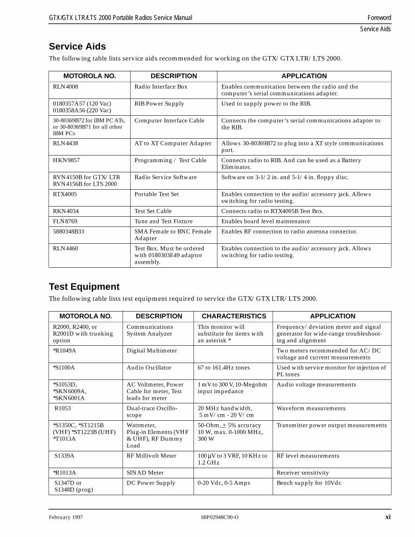
Service Aids
Service Aids
The following table lists service aids recommended for working on the GTX/GTX LTR/LTS 2000.
Test Equipment
The following table lists test equipment required to service the GTX/GTX LTR/LTS 2000.
MOTOROLA NO. DESCRIPTION APPLICATION
RLN4008 Radio Interface Box Enables communication between the radio and the computer’s serial communications adapter.
0180357A57 (120 Vac)0180358A56 (220 Vac)
RIB Power Supply Used to supply power to the RIB.
30-80369B72 for IBM PC ATs, or 30-80369B71 for all other IBM PCs
Computer Interface Cable Connects the computer’s serial communications adapter to the RIB.
RLN4438 AT to XT Computer Adapter Allows
30-80369B72 to plug into a XT style communications port.
HKN9857 Programming / Test Cable Connects radio to RIB. And can be used as a Battery Eliminator.
RVN4150B for GTX/LTRRVN4156B for LTS 2000
Radio Service Software Software on 3-1/2 in. and 5-1/4 in. floppy disc.
RTX4005 Portable Test Set Enables connection to the audio/accessory jack. Allows switching for radio testing.
RKN4034 Test Set Cable Connects radio to RTX4005B Test Box.
FLN8769 Tune and Test Fixture Enables board level maintenance
5880348B33 SMA Female to BNC Female Adapter
Enables RF connection to radio antenna connector.
RLN4460 Test Box. Must be ordered with 0180303E49 adaptorassembly.
Enables connection to the audio/accessory jack. Allows switching for radio testing.
MOTOROLA NO. DESCRIPTION CHARACTERISTICS APPLICATION
R2000, R2400, or R2001D with trunking option
Communications System Analyzer
This monitor will substitute for items with an asterisk *
Frequency/deviation meter and signal generator for wide-range troubleshoot-ing and alignment
*R1049A Digital Multimeter Two meters recommended for AC/DC voltage and current measurements
*S1100A Audio Oscillator 67 to 161.4Hz tones Used with service monitor for injection of PL tones
*S1053D, *SKN6009A, *SKN6001A
AC Voltmeter, Power Cable for meter, Test leads for meter
1 mV to 300 V, 10-Megohm input impedance
Audio voltage measurements
R1053 Dual-trace Oscillo-scope
20 MHz bandwidth, 5 mV/cm - 20 V/cm
Waveform measurements
*S1350C, *ST1215B (VHF) *ST1223B (UHF) *T1013A
Wattmeter,Plug-in Elements (VHF & UHF), RF Dummy Load
50-Ohm, + 5% accuracy 10 W, max. 0-1000 MHz, 300 W
Transmitter power output measurements
S1339A RF Millivolt Meter 100
µ
V to 3 VRF, 10 KHz to 1.2 GHz
RF level measurements
*R1013A SINAD Meter Receiver sensitivity
S1347D or S1348D (prog)
DC Power Supply 0-20 Vdc, 0-5 Amps Bench supply for 10Vdc
xii 68P02948C90-O February 1997
Foreword GTX/GTX LTR/LTS 2000 Portable Radios Service Manual
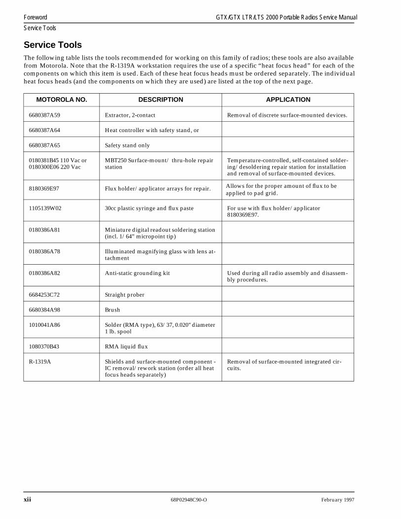
Service Tools
Service ToolsThe following table lists the tools recommended for working on this family of radios; these tools are also availablefrom Motorola. Note that the R-1319A workstation requires the use of a specific “heat focus head” for each of thecomponents on which this item is used. Each of these heat focus heads must be ordered separately. The individualheat focus heads (and the components on which they are used) are listed at the top of the next page.
MOTOROLA NO. DESCRIPTION APPLICATION
6680387A59 Extractor, 2-contact Removal of discrete surface-mounted devices.
6680387A64 Heat controller with safety stand, or
6680387A65 Safety stand only
0180381B45 110 Vac or 0180300E06 220 Vac
MBT250 Surface-mount/ thru-hole repair station
Temperature-controlled, self-contained solder-ing/desoldering repair station for installation and removal of surface-mounted devices.
8180369E97 Flux holder/applicator arrays for repair. Allows for the proper amount of flux to be applied to pad grid.
1105139W02 30cc plastic syringe and flux paste For use with flux holder/applicator 8180369E97.
0180386A81 Miniature digital readout soldering station (incl. 1/64” micropoint tip)
0180386A78 Illuminated magnifying glass with lens at-tachment
0180386A82 Anti-static grounding kit Used during all radio assembly and disassem-bly procedures.
6684253C72 Straight prober
6680384A98 Brush
1010041A86 Solder (RMA type), 63/37, 0.020" diameter 1 lb. spool
1080370B43 RMA liquid flux
R-1319A Shields and surface-mounted component - IC removal/rework station (order all heat focus heads separately)
Removal of surface-mounted integrated cir-cuits.
February 1997 68P02948C90-O
xiii
GTX/GTX LTR/LTS 2000 Portable Radios Service Manual Foreword
Service Tools
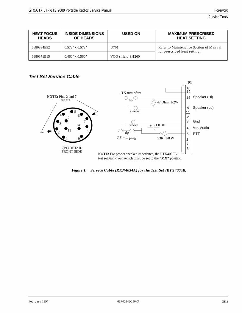
Test Set Service Cable
HEAT-FOCUS HEADS
INSIDE DIMENSIONSOF HEADS
USED ON MAXIMUM PRESCRIBEDHEAT SETTING
6680334B52 0.572" x 0.572" U701 Refer to Maintenance Section of Manual for prescribed heat setting.
6680371B15 0.460" x 0.560" VCO shield SH260
612
14
1123
4
5
178
95
6
7
8
91
14
4
3
2
12
11
(P1) DETAIL FRONT SIDE
NOTE: Pins 2 and 7 are cut.
P1
3.5 mm plug
2.5 mm plug 33K, 1/8 W
1.0 µF
47 Ohm, 1/2W
+
sleeve
tip
sleeve
tip
NOTE: For proper speaker impedance, the RTX4005Btest set Audio out switch must be set to the “MX” position
Speaker (Hi)
Speaker (Lo)
Gnd
Mic. Audio
PTT
Figure 1. Service Cable (RKN4034A) for the Test Set (RTX4005B)
xiv
68P02948C90-O February 1997
Foreword GTX/GTX LTR/LTS 2000 Portable Radios Service Manual
Radio Model Numbering System
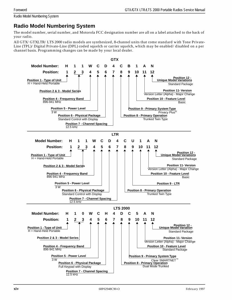
Radio Model Numbering System
The model number, serial number, and Motorola FCC designation number are all on a label attached to the back of your radio.
All GTX/GTXLTR/LTS 2000 radio models are synthesized, 8-channel units that come standard with Tone Private-Line (TPL)/Digital Private-Line (DPL) coded squelch or carrier squelch, which may be enabled/disabled on a per channel basis. Programming changes can be made by your local dealer.
H 1 1 W C D 4 C B 1 A N
Position 1 - Type of UnitH = Hand-Held Portable
Model Number:
Position: 1 2 3 4 5 6 7 8 9 10 11 12
Position 4 - Frequency Band
Position 2 & 3 - Model Series
Position 5 - Power Level
Position 6 - Physical Package
Position 12 -
Position 10 - Feature Level
Position 8 - Primary Operation
Position 11- Version
Position 9 - Primary System Type
896-941 MHz
3 W
Standard Control with Display
Position 7 - Channel Spacing12.5 kHz
Unique Model VariationsStandard Package
Version Letter (Alpha) - Major Change
Basic
Privacy Plus®
Trunked Twin Type
H 1 0 W C H 4 D C 5 A N
Position 1 - Type of UnitH = Hand-Held Portable
Model Number:
Position: 1 2 3 4 5 6 7 8 9 10 11 12
Position 4 - Frequency Band
Position 2 & 3 - Model Series
Position 5 - Power Level
Position 6 - Physical Package
Position 12 -
Position 10 - Feature Level
Position 8 - Primary Operation
Position 11- Version
Position 9 - Primary System Type
896-941 MHz
3 W
Full Keypad with Display
Position 7 - Channel Spacing12.5 kHz
Unique Model VariationStandard Package
Version Letter (Alpha) - Major Change
Standard Package
Clear SMARTNET™
Dual Mode Trunked
H 1 1 W C D 4 C U 1 A N
Position 1 - Type of UnitH = Hand-Held Portable
Model Number:
Position: 1 2 3 4 5 6 7 8 9 10 11 12
Position 4 - Frequency Band
Position 2 & 3 - Model Series
Position 5 - Power Level
Position 6 - Physical Package
Position 12 -
Position 10 - Feature Level
Position 8 - Primary Operation
Position 11- Version
Position 9 - LTR
896-941 MHz
3 W
Standard Control with Display
Position 7 - Channel Spacing12.5 kHz
Unique Model VariationsStandard Package
Version Letter (Alpha) - Major Change
Basic
Trunked Twin Type
GTX
LTR
LTS 2000
February 1997 68P02948C90-O
xv
GTX/GTX LTR/LTS 2000 Portable Radios Service Manual Foreword
Radio Service Software Information
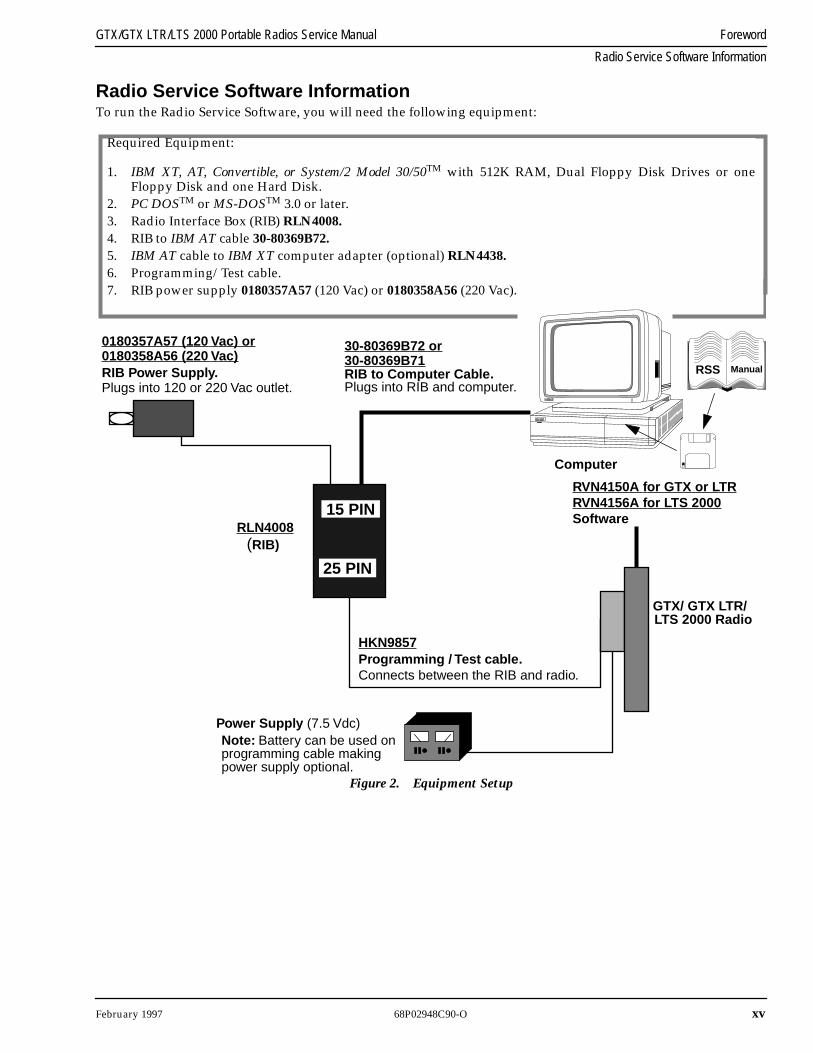
Radio Service Software Information
To run the Radio Service Software, you will need the following equipment:
Software
RIB Power Supply. Plugs into 120 or 220 Vac outlet.
Computer
GTX/ GTX LTR/
RLN4008(RIB)
30-80369B72 or
RIB to Computer Cable.Plugs into RIB and computer.
Connects between the RIB and radio.Programming / Test cable.
Power Supply (7.5 Vdc)
HKN9857
RVN4150A for GTX or LTR
Note: Battery can be used onprogramming cable makingpower supply optional.
RSS Manual
15 PIN
25 PIN
Required Equipment:
1. IBM XT, AT, Convertible, or System/2 Model 30/50TM with 512K RAM, Dual Floppy Disk Drives or oneFloppy Disk and one Hard Disk.
2. PC DOSTM or MS-DOSTM 3.0 or later.3. Radio Interface Box (RIB) RLN4008.4. RIB to IBM AT cable 30-80369B72.5. IBM AT cable to IBM XT computer adapter (optional) RLN4438.6. Programming/Test cable.7. RIB power supply 0180357A57 (120 Vac) or 0180358A56 (220 Vac).
Figure 2. Equipment Setup
LTS 2000 Radio
0180357A57 (120 Vac) or0180358A56 (220 Vac)
RVN4156A for LTS 2000
30-80369B71
xvi 68P02948C90-O February 1997
Foreword GTX/GTX LTR/LTS 2000 Portable Radios Service Manual
Configuring the RIB and Radio
Configuring the RIB and Radio1. Connect the RIB to the computer (Figure 2).2. Plug the large 25-pin end of the HKN9857 programming cable into the RIB. The other end of this cable has
a “battery eliminator.”3. Slide the battery eliminator in place of the radio’s battery.
4. Plug power supply 0180357A57 (120 Vac) or 0180358A56 (220 Vac) into a wall outlet, and connect the otherend to the RIB.
5. Connect the radio to a power supply and turn the volume control clockwise to turn it on.
February 1997 68P02948C90-O xvii
GTX/GTX LTR/LTS 2000 Portable Radios Service Manual Foreword
Important Safety Information: Intrinsically Safe Radios
Important Safety Information: Intrinsically Safe Radios
FMRC Approved Equipment
Anyone intending to use a radio in a location where hazardous concentrations of flammable material exist (hazardous atmo-sphere) is advised to become familiar with the subject of intrinsic safety and with the National Electric Code NFPA 70 (National Fire Protection Association) Article 500 (hazardous [classified] locations).
An Approval Guide, issued by Factory Mutual Research Corporation (FMRC), lists manufacturers and the products approved by FMRC for use in such locations. FMRC has also issued a voluntary approval standard for repair service (“Class Number 3605").
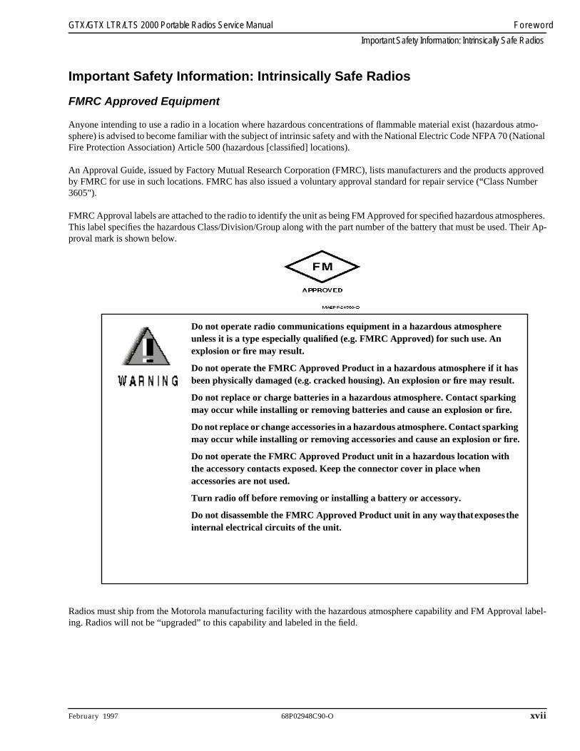
FMRC Approval labels are attached to the radio to identify the unit as being FM Approved for specified hazardous atmospheres. This label specifies the hazardous Class/Division/Group along with the part number of the battery that must be used. Their Ap-proval mark is shown below.
Radios must ship from the Motorola manufacturing facility with the hazardous atmosphere capability and FM Approval label-ing. Radios will not be “upgraded” to this capability and labeled in the field.
Do not operate radio communications equipment in a hazardous atmosphere unless it is a type especially qualified (e.g. FMRC Approved) for such use. An explosion or fire may result.
Do not operate the FMRC Approved Product in a hazardous atmosphere if it has been physically damaged (e.g. cracked housing). An explosion or fire may result.
Do not replace or charge batteries in a hazardous atmosphere. Contact sparking may occur while installing or removing batteries and cause an explosion or fire.
Do not replace or change accessories in a hazardous atmosphere. Contact sparking may occur while installing or removing accessories and cause an explosion or fire.
Do not operate the FMRC Approved Product unit in a hazardous location with the accessory contacts exposed. Keep the connector cover in place when accessories are not used.
Turn radio off before removing or installing a battery or accessory.
Do not disassemble the FMRC Approved Product unit in any way that exposes the internal electrical circuits of the unit.
xviii 68P02948C90-O February 1997
Foreword GTX/GTX LTR/LTS 2000 Portable Radios Service Manual
Important Safety Information: Intrinsically Safe Radios
A modification changes the unit's hardware from its original design configuration. Modifications can only be done by the orig-inal product manufacturer at one of its FMRC audited manufacturing facilities.
Repair of FMRC Approved Products
REPAIRS FOR MOTOROLA FMRC APPROVED PRODUCTS ARE THE RESPONSIBILITY OF THE USER.
You should not repair or relabel any Motorola manufactured communication equipment bearing the FMRC Approval label (“FMRC Approved Product”) unless you are familiar with the current FMRC Approval Standard for repair service (“Class Num-ber 3605").
You may want to consider using a repair facility that operates under 3605 repair service approval.
FMRC's Approval Standard Class Number 3605 is subject to change at any time without notice to you, so you may want to obtain a current copy of 3605 from FMRC. Per the December, 1994 publication of 3605, some key definitions and service re-quirements are as follows:
Repair
A repair constitutes something done internally to the unit that would bring it back to its original condition Approved by FMRC. A repair should be done in an FMRC Approved facility.
Items not considered as repairs are those in which an action is performed on a unit which does not require the outer casing of the unit to be opened in a manner which exposes the internal electrical circuits of the unit. You do not have to be an FMRC Approved Repair Facility to perform these actions.
The radio support center is at the following address: Motorola Radio Support Center3651 South Central AvenueRockford, Ill, 61102Telephone: (800) 227-6772 (815) 489-1000
Failure to use an FMRC Approved Product unit with an FMRC Approved battery or FMRC Approved accessories specifically approved for that product may result in the dangerously unsafe condition of an unapproved radio combination being used in a hazardous location.
Unauthorized or incorrect modification of an FMRC Approved Product unit will negate the Approval rating of the product.
Incorrect repair or relabeling of any FMRC Approved Product unit could adversely affect the Approval rating of the unit.
Use of a radio that is not intrinsically safe in a hazardous atmosphere could result in serious injury or death.
February 1997 68P02948C90-O xix
GTX/GTX LTR/LTS 2000 Portable Radios Service Manual Foreword
Vehicles Equipped with Air Bags
Relabeling
The repair facility shall have a method by which the replacement of FMRC Approval labels are controlled to ensure that any relabeling is limited to units that were originally shipped from the Manufacturer with an FM Approval label in place. FMRC Approval labels shall not be stocked by the repair facility. An FMRC Approval label shall be ordered from the original manu-facturer as needed to repair a specific unit. Replacement labels may be obtained and applied by the repair facility providing satisfactory evidence that the unit being relabeled was originally an FMRC Approved unit. Verification may include, but is not limited to: a unit with a damaged Approval label, a unit with a defective housing displaying an Approval label, or a customer invoice indicating the serial number of the unit and purchase of an FMRC Approved model.
Do Not Substitute Options or Accessories
The communications equipment package that Motorola submits to FMRC for testing and approval is tested as a system that consists of the communications unit itself and the battery, antenna and other options or accessories that make up the rest of the package to be approved. This approved package must be strictly observed and there must be no substitution of items, even if the substitute you wanted to consider appears as an approved accessory elsewhere in the Guide for some other communications equipment unit. Approved configurations are listed by FMRC Approved Product in the annual Approval Guide published by FMRC. That guide, and the Approval Standard Class Number 3605 document, can be ordered from the following address.
Training Resource Center, Publications-Order Processing Dept. Factory Mutual Engineering and Research1151 Boston-Providence TurnpikePO Box 9102Norwood, MA, 02062Telephone: (617) 762-4300
Vehicles Equipped with Air Bags
When planning the installation of communication equipment in a vehicle with one or more air bags, proceed as follows:
• Installation of vehicle equipment should be performed by a professional installer/technician qualified in the requirements for such installations. An air bag’s size, shape and deployment area can vary by vehicle make, model and front compartment configuration (e.g., bench seat vs. bucket seats).
• Contact the vehicle manufacturer’s corporate headquarters, if necessary, for specific air bag information for the vehicle make, model and front compartment configuration involved in your communication equipment instal-lation.
Vehicles equipped with air bags. An air bag inflates with great force. DO NOT place objects, including communication equipment, in the area over the air bag or in the air bag deployment area. If the communication equipment is improperly installed and the air bag inflates, this could cause serious injury.

xx 68P02948C90-O February 1997
Foreword GTX/GTX LTR/LTS 2000 Portable Radios Service Manual
This page intentionally left blank
February 1997 68P02948C90-O 1-1
Section 1Radio Disassembly/Assembly
OverviewThis section explains, step by step, how to disassembleand reassemble the GTX/GTX LTR/LTS 2000 radios.
Safety Information
When testing and repairing the GTX/GTX LTR/LTS2000 radios, observe the handling precautions to pre-vent unnecessary damage to the GTX/GTX LTR/LTS2000 radios.
• Minimize handling of static-sensitive compo-nents and modules.
• Transport and store static-sensitive componentsor assemblies in their original containers on ametal rail. Label any package that containsstatic-sensitive components or assemblies.
• Discharge static electricity from the body bywearing a grounded antistatic wrist strap whilehandl ing these components . Servic ingstatic-sensitive components or assembliesshould only be done at a static-free work stationby qualified service technicians. Increasing thehumidity in the work area minimizes static elec-tricity problems.
• Do not allow anything that can generate or holda static charge on the workstation surface.
• Keep the component leads shorted togetherwhenever possible.
• Pick up components by their bodies. Never pickthem up by their leads.
• Do not slide the components over any surface.
• Avoid handling components in areas with afloor or work surface covering that can generatea static charge.
• Use a soldering iron connected to earth ground.
• Use only approved, anti-static, vacuum-typedesoldering tools for removing components.
• When removing printed circuit boards (PCBs),remove the screws in a diagonal pattern toreduce stress on the boards.
Radio Disassembly
Battery Removal
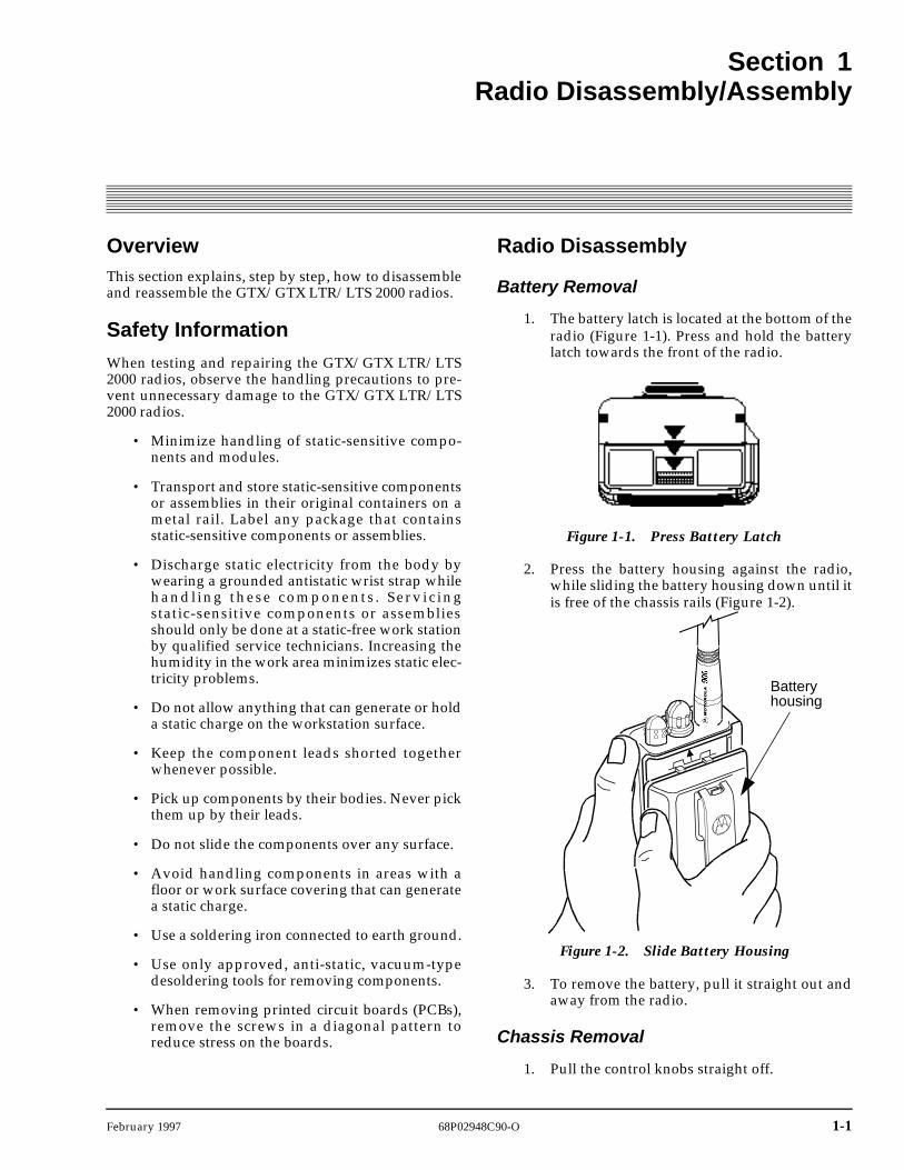
1. The battery latch is located at the bottom of theradio (Figure 1-1). Press and hold the batterylatch towards the front of the radio.
2. Press the battery housing against the radio,while sliding the battery housing down until itis free of the chassis rails (Figure 1-2).
3. To remove the battery, pull it straight out andaway from the radio.
Chassis Removal
1. Pull the control knobs straight off.
Figure 1-1. Press Battery Latch
Figure 1-2. Slide Battery Housing
Batteryhousing
1-2 68P02948C90-O February 1997
Radio Disassembly/Assembly GTX/GTX LTR/LTS 2000 Portable Radios Service Manual
Radio Disassembly
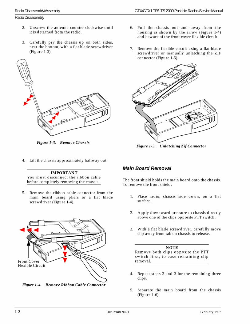
2. Unscrew the antenna counter-clockwise untilit is detached from the radio.
3. Carefully pry the chassis up on both sides,near the bottom, with a flat blade screwdriver(Figure 1-3).
4. Lift the chassis approximately halfway out.
IMPORTANTYou must disconnect the ribbon cablebefore completely removing the chassis.
5. Remove the ribbon cable connector from themain board using pliers or a flat bladescrewdriver (Figure 1-4).
Figure 1-3. Remove Chassis
Figure 1-4. Remove Ribbon Cable Connector
Front CoverFlexible Circuit
6. Pull the chassis out and away from thehousing as shown by the arrow (Figure 1-4)and beware of the front cover flexible circuit.
7. Remove the flexible circuit using a flat-bladescrewdriver or manually unlatching the ZIFconnector (Figure 1-5).
Main Board Removal
The front shield holds the main board onto the chassis.To remove the front shield:
1. Place radio, chassis side down, on a flatsurface.
2. Apply downward pressure to chassis directlyabove one of the clips opposite PTT switch.
3. With a flat blade screwdriver, carefully moveclip away from tab on chassis to release.
NOTERemove both clips opposite the PTTswitch first, to ease remaining clipremoval.
4. Repeat steps 2 and 3 for the remaining threeclips.
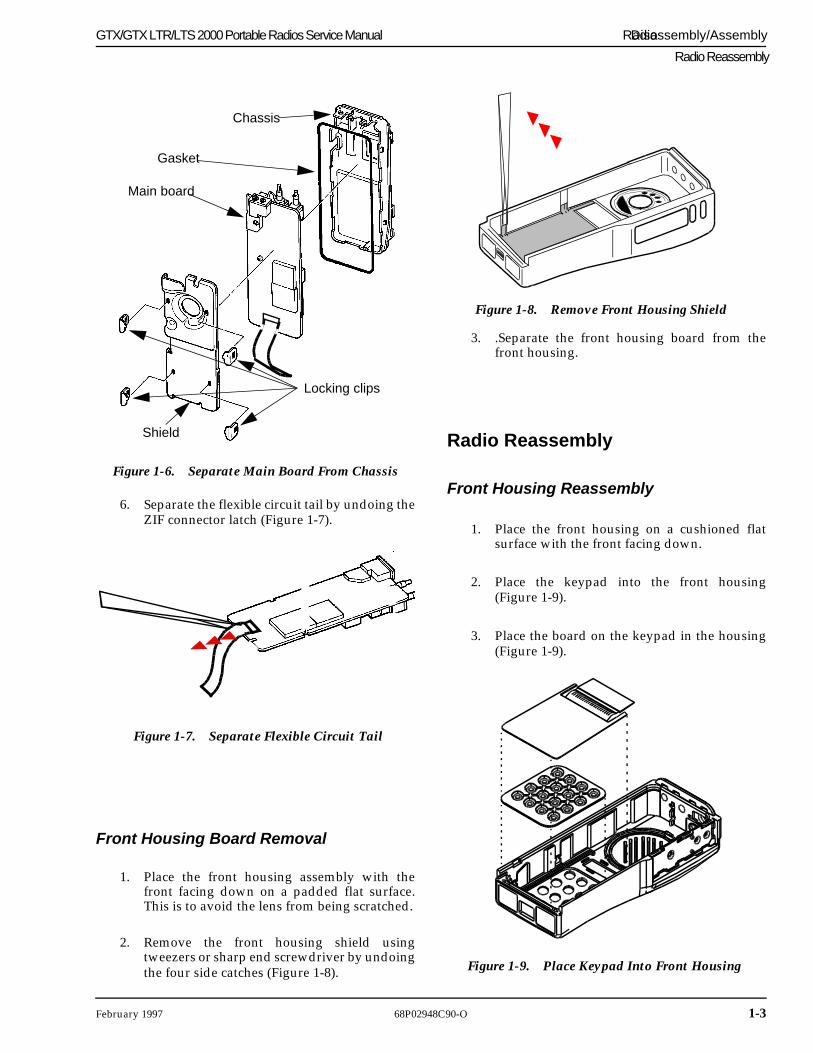
5. Separate the main board from the chassis(Figure 1-6).
Figure 1-5. Unlatching Zif Connector
February 1997 68P02948C90-O 1-3
GTX/GTX LTR/LTS 2000 Portable Radios Service Manual Radio Disassembly/Assembly
Radio Reassembly
6. Separate the flexible circuit tail by undoing theZIF connector latch (Figure 1-7).
Front Housing Board Removal
1. Place the front housing assembly with thefront facing down on a padded flat surface.This is to avoid the lens from being scratched.
2. Remove the front housing shield usingtweezers or sharp end screwdriver by undoingthe four side catches (Figure 1-8).
Figure 1-6. Separate Main Board From Chassis
Locking clips
Main board
Chassis
Gasket
Shield
Figure 1-7. Separate Flexible Circuit Tail
3. .Separate the front housing board from thefront housing.
Radio Reassembly
Front Housing Reassembly
1. Place the front housing on a cushioned flatsurface with the front facing down.
2. Place the keypad into the front housing(Figure 1-9).
3. Place the board on the keypad in the housing(Figure 1-9).
Figure 1-8. Remove Front Housing Shield
Figure 1-9. Place Keypad Into Front Housing
1-4 68P02948C90-O February 1997
Radio Disassembly/Assembly GTX/GTX LTR/LTS 2000 Portable Radios Service Manual
Radio Reassembly
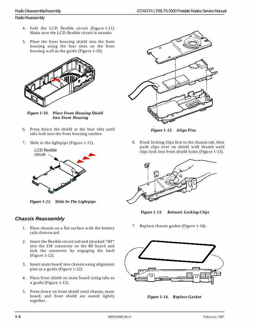
4. Fold the LCD flexible circuit (Figure 1-11).Make sure the LCD flexible circuit is outside.
5. Place the front housing shield into the fronthousing using the four slots on the fronthousing wall as the guide (Figure 1-10).
6. Press down the shield at the four tabs untiltabs lock into the front housing catches.
7. Slide in the lightpipe (Figure 1-11).
Chassis Reassembly
1. Place chassis on a flat surface with the batteryrails downward.
2. Insert the flexible circuit tail end (marked “RF”into the ZIF connector on the RF board andlock the connector by engaging the latch(Figure 1-12).
3. Insert main board into chassis using alignmentpins as a guide (Figure 1-12).
4. Place front shield on main board using tabs asa guide (Figure 1-12).
5. Press down on front shield until chassis, mainboard, and front shield are seated tightlytogether.
Figure 1-10. Place Front Housing Shield Into Front Housing
Figure 1-11. Slide In The Lightpipe
LCD flexible circuit
6. Hook locking clips first to the chassis tab, thenpush clips over on shield with thumb untilclips lock into front shield holes (Figure 1-13).
7. Replace chassis gasket (Figure 1-14).
Figure 1-12. Align Pins
Figure 1-13. Reinsert Locking Clips
Figure 1-14. Replace Gasket
February 1997 68P02948C90-O 1-5
GTX/GTX LTR/LTS 2000 Portable Radios Service Manual Radio Disassembly/Assembly
Radio Reassembly
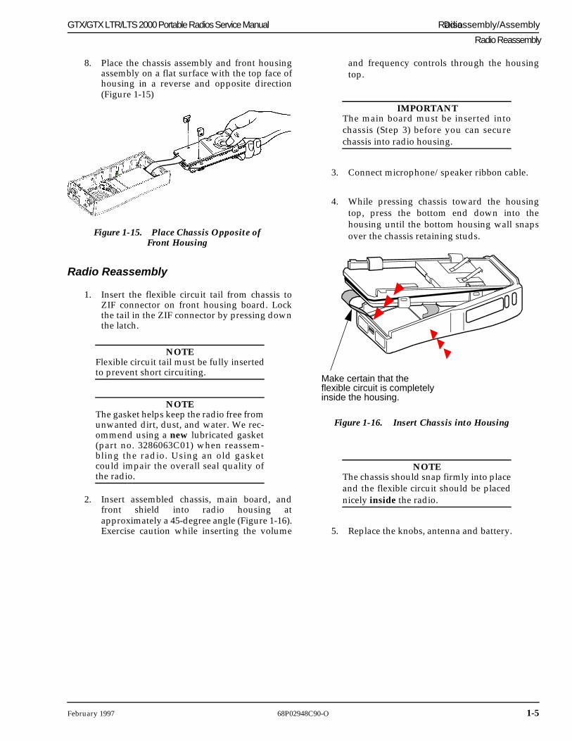
8. Place the chassis assembly and front housingassembly on a flat surface with the top face ofhousing in a reverse and opposite direction(Figure 1-15)
Radio Reassembly
1. Insert the flexible circuit tail from chassis toZIF connector on front housing board. Lockthe tail in the ZIF connector by pressing downthe latch.
NOTEFlexible circuit tail must be fully insertedto prevent short circuiting.
NOTEThe gasket helps keep the radio free fromunwanted dirt, dust, and water. We rec-ommend using a new lubricated gasket(part no. 3286063C01) when reassem-bling the radio. Using an old gasketcould impair the overall seal quality ofthe radio.
2. Insert assembled chassis, main board, andfront shield into radio housing atapproximately a 45-degree angle (Figure 1-16).Exercise caution while inserting the volume
Figure 1-15. Place Chassis Opposite of Front Housing
and frequency controls through the housingtop.
IMPORTANTThe main board must be inserted intochassis (Step 3) before you can securechassis into radio housing.
3. Connect microphone/speaker ribbon cable.
4. While pressing chassis toward the housingtop, press the bottom end down into thehousing until the bottom housing wall snapsover the chassis retaining studs.
NOTEThe chassis should snap firmly into placeand the flexible circuit should be placednicely inside the radio.
5. Replace the knobs, antenna and battery.
Figure 1-16. Insert Chassis into Housing
Make certain that the flexible circuit is completelyinside the housing.

1-6 68P02948C90-O February 1997
Radio Disassembly/Assembly GTX/GTX LTR/ LTS 2000 Portable Radios Service Manual
This page intentionally left blank
February 1997 68P02948C90-O 2-1
Section 2Theory of Operation
Overview
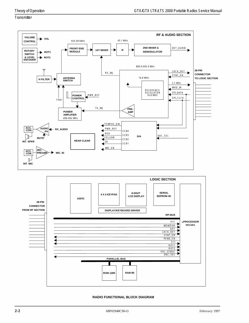
This section provides a detailed theory of operation forthe GTX/GTX LTR/LTS 2000 radios and its compo-nents: the receiver, transmitter, frequency generationcircuitry, controller and audio & data circuitry.
Receiver
The receiver of the GTX/GTX LTR/LTS 2000 radiosconsists of 4 major blocks: the front-end module, dou-ble balanced mixer, 45.1 MHz IF, and back-end IF IC.
The GTX/GTX LTR/LTS 2000 front-end modules con-sist of three blocks of circuitry: a ceramic pre-selectorfilter, RF amplifier and ceramic post-selector filter.
The ceramic pre- and post-selector filters are 3-pole,bandpass filters. This topology maximizes the attenua-tion at the worst case image frequency for this receiver,which is 90.2 MHz below the filter Passband. The 3 dBbandwidth is approximately 12/22 MHz for 900 MHzrespectively, centered at 937 MHz for 900 MHz respec-tively. The center of the band insertion loss is approxi-mately 2 dB. The 3-pole filters are designed to operatewith a 50 Ohm input and output termination.
The RF amplifier, Q1, is a Motorola MRF9411 NPNdevice biased in a common emitter configuration. Theamp is stabilized by the shunt feedback coil L2, and hasapproximately 15 dB of gain with a noise figure ofabout 2 dB. The amplifier draws 6.5 mA of current andis supplied by the receiver 5 V supply (indicated as“5R” on the schematics and block diagrams).
Terminating the RF amplifier is the post-selector filter.This filter is the same as the pre-filter.
The net gain of the receiver front-end module is about12 dB in the center of the band and about 11.5 dB at theband edges. The net center of the band noise figure isapproximately 4.5 dB.
The receiver mixer is a double-balanced mixer whichprovides excellent protection against receiver spursdue to non-linearities, such as IM and half-IF. Thereceived signal mixes down to the frequency of the firstIF, 45.1 MHz, and enters the IF circuitry. The mixeroperates with a LO level of +3 dBm and a conversionloss of about 7 dB.
Intermediate Frequency (IF)
The Intermediate Frequency (IF) section of the portableradio consists of several sections including the high IF,the second LO, the second IF, and the IF IC chip. Thefirst LO signal and the RF signal mix to the IF fre-quency of 45.1 MHz, and then enters the IF portion ofthe radio.
The signal first enters the high IF, passes through acrystal filter, is amplified by the IF amp, and thenpassed through a second crystal filter. The first crystalfilter provides selectivity, second image protection, andintermodulation protection. The amplifier providesapproximately 16 dB of gain to the signal. The signalthen passes through the second crystal filter which pro-vides further selectivity and second image protection.The high IF has an approximate 3 dB bandwidth of7 KHz.
The filtered and amplified IF signal is mixed with thesecond local oscillator at 44.645 MHz. The second LOuses an amplifier internal to the IF IC, an external crys-tal and some external chip parts. The oscillator pre-sents an approximate level of -15 dBm to the second IFmixer, internal to the IF IC.
The mixed output of the IF signal and the second LO,produces a 455 KHz signal (second IF). This signal isthen filtered by external ceramic filters and amplified.It is then passed back to the IF IC, sent to a phase-lockdetector, and demodulated. The resulting detectedaudio output is then sent to the ASFIC to recover theaudio.
Transmitter
The transmitter contains five basic circuits: a poweramplifier, an antenna switch, a harmonic filter, anantenna matching network, and a power control. Referto the block diagram and the schematic for more infor-mation.
The power amplifier is an LD-MOS module. This mod-ule contains a 3-stage amplification with a supply volt-age at 7.5 V. The LD-MOS is capable of supplying anoutput power of 4.4 W with an input signal of 1 mW.The power output can be varied by changing the bias-ing voltage at the first stage.
2-2 68P02948C90-O February 1997
Theory of Operation GTX/GTX LTR/LTS 2000 Portable Radios Service Manual
Transmitter
ANTENNA SWITCH
FRONT-ENDMODULE
H FILTER
POWERAMPLIFIER
935-941MHz
1ST MIXER IF
45.1 MHz
2ND MIXER &
DEMODULATOR
DET_AUDIO
RX_INJ
POWERCONTROL
PWR_REF
TX_INJ
16.8 MHz
REFERENCE
TEMPUS_D/A
PWR_REF
RED
YELLOW
5R
MIC_EN
SCB4
SCB3
SCB2
SCB1
D/A DAC_SEL
LOCK_DET
SYNT_EN
2.1 MHz
MOD_IN
SPI_DATA
SPI_CLCK
PRE-AMP
TXB+
889.9-995.9 MHz
RF & AUDIO SECTION
µPROCESSORHC11K1
SERIALEEPROM 4K
8-DIGIT LCD DISPLAY
4 X 4 KEYPAD
DISPLAY/KEYBOARD DRIVER
ASFIC
PARALLEL BUS
SPI BUS
PTT
MONITOR
OPTLOCK_DET
SYNT_EN
PEND_EN
SCI
ROT1ROT2
VOL_SENSEDAC_SEL
RAM 8KROM 128K
LOGIC SECTION
28-PIN
CONNECTOR
TO LOGIC SECTION
28-PIN
CONNECTOR
FROM RF SECTION
VOLUME
ROTARYSWITCH& LEVEL
CONTROL
ENCODER
VOL
ROT1
ROT2
RX_AUDIO
MUTEINT. SPKR
ACC. AUDIOPA
896-902 MHz
CON.
MIC_IN
INT. MIC
ACC. MIC.PREAMP CON.
OSCILLATOR16.8 MHZ
HEAR CLEAR
RADIO FUNCTIONAL BLOCK DIAGRAM