Embed Size (px)
Citation preview
AETA AUDIO SYSTEMS 18-22, avenue Edouard Herriot – Kepler 4 – 92350 Le Plessis Robinson – FRANCE
Tél. +33 1 41 36 12 00 – Fax +33 1 41 36 12 69 – Web: http://www.aeta-audio.com
55 000 057 - B MIXY - User Manual Specifications subject to change – All rights reserved by AAS August 07 55000057-b_mixy_en.doc
MIXYPortable Stereo and M/S
Analog/Digital Mixer
User Manual


55 000 057 - B MIXY - User Manual
Table of contents
1. Main technical characteristics...........................................2
2. Functions .............................................................................3
2.1. “Mic/Line”........................................................................................... 3
2.2. “EXT I/O” socket, radio receivers ....................................................... 5
2.3. USB and auxiliary Return/Line In ....................................................... 6
2.4. Analog outputs..................................................................................... 6
2.5. Monitor ................................................................................................ 7
2.6. Digital outputs ..................................................................................... 9
2.7. SPDIF digital input ............................................................................ 10
2.8. USB interface .................................................................................... 10
2.9. Internal alignment signal generator ................................................... 11
2.10. Intercom / Slate microphone............................................................ 11
2.11. Power supply ................................................................................... 11
3. Operating mode – Detailed description..........................12
3.1. Switching on and off.......................................................................... 12
3.2. General principles.............................................................................. 12
3.3. Mic/Line 1 and 2 operating mode...................................................... 13
3.4. Settings for Mic/Line inputs .............................................................. 13
3.5. Auxiliary Inputs ................................................................................. 16
3.6. Parameters of the “Line Out” (XLR5M) interfaces ........................... 17
3.7. Levels for the outputs to RF transmitters........................................... 18
3.8. Parameters of the digital outputs ....................................................... 18
3.9. Monitoring ......................................................................................... 19
3.10. Miscellaneous functions .................................................................. 20
3.11. Save or recall a complete setup........................................................ 21
3.12. Programmable key ........................................................................... 21
3.13. Using the L/R M/S transcoding .................................................. 22
4. Technical specifications....................................................26
4.1. Microphone/Line inputs..................................................................... 26
4.2. "Line Out" balanced analog outputs .................................................. 27
MIXY - User Manual 55 000 057 - B
4.3. "Line Out" unbalanced analog outputs ...............................................27
4.4. Headphone output ..............................................................................28
4.5. External DC supply ............................................................................28
4.6. "EXT I/O": Interface for RF transmitters/receivers............................29
4.7. Digital outputs and direct analog outputs ...........................................30
4.8. Power supply ......................................................................................31
4.9. Dimensions and weight ......................................................................32
4.10. Environmental ..................................................................................32
4.11. Versions - Options............................................................................32
4.12. Accessories.......................................................................................32
5. Annexes .............................................................................33
5.1. General block diagram .......................................................................33
5.2. Overview of connectors and front panel elements .............................34
5.3. Level maps .........................................................................................36
55 000 057 - B MIXY - User Manual 1
Introduction MIXY is a portable mixer specially designed for outside recording (ENG).
MIXY is ideally suitable for production, thanks to its outstanding audio
characteristics and full compatibility with “M/S” systems. MIXY includes three
Mic/Line inputs, with comprehensive powering and limiting features.
With no need for complex recording level setting, the “AES” and “Toslink” digital
outputs can directly feed digital inputs of audio recorders such as DAT, CD, D-D,
M-C and MiniDisc.
The bold and italic numbers (for instance: 3) refer to the captions in the pictures of
annex 5.2 (Overview of connectors and front panel ).
2 MIXY - User Manual 55 000 057 - B
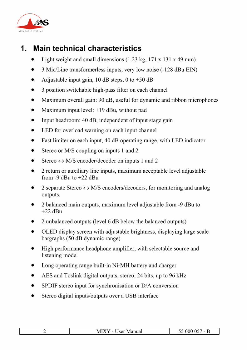
1. Main technical characteristics
Light weight and small dimensions (1.23 kg, 171 x 131 x 49 mm)
3 Mic/Line transformerless inputs, very low noise (-128 dBu EIN)
Adjustable input gain, 10 dB steps, 0 to +50 dB
3 position switchable high-pass filter on each channel
Maximum overall gain: 90 dB, useful for dynamic and ribbon microphones
Maximum input level: +19 dBu, without pad
Input headroom: 40 dB, independent of input stage gain
LED for overload warning on each input channel
Fast limiter on each input, 40 dB operating range, with LED indicator
Stereo or M/S coupling on inputs 1 and 2
Stereo M/S encoder/decoder on inputs 1 and 2
2 return or auxiliary line inputs, maximum acceptable level adjustable
from -9 dBu to +22 dBu
2 separate Stereo M/S encoders/decoders, for monitoring and analog
outputs.
2 balanced main outputs, maximum level adjustable from -9 dBu to
+22 dBu
2 unbalanced outputs (level 6 dB below the balanced outputs)
OLED display screen with adjustable brightness, displaying large scale
bargraphs (50 dB dynamic range)
High performance headphone amplifier, with selectable source and
listening mode.
Long operating range built-in Ni-MH battery and charger
AES and Toslink digital outputs, stereo, 24 bits, up to 96 kHz
SPDIF stereo input for synchronisation or D/A conversion
Stereo digital inputs/outputs over a USB interface

55 000 057 - B MIXY - User Manual 3
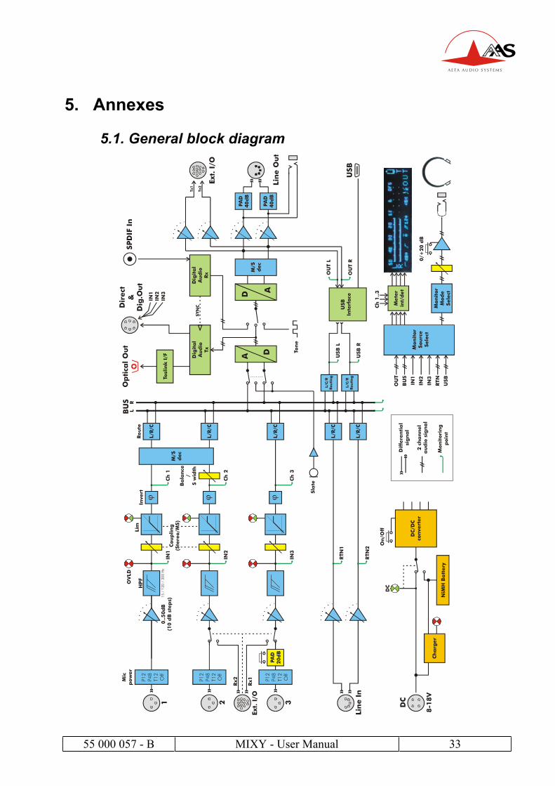
2. Functions The functions of the mixer are shown on the functional diagram that can be found in
annex 5.1, “General block diagram ”
2.1. “Mic/Line”
Each of these three inputs is available on a 3-pin female XLR socket, and is
electronically balanced.
If no powering is active, unbalancing an input has no negative impact on the
performance.
Microphones can be powered in « phantom » mode or “Tonader 12V”, with
separate setting for each input. In phantom mode, 12V or 48V can be selected.
Inputs 2 and 3 can also be fed from the “EXT I/O” socket, in which case no
microphone powering is available.
Channel 2 features a +/-5 dB gain trimmer, for adjusting the balance in stereo mode
or the width in M/S mode.
Input 3 can stand very strong audio levels thanks to a 20 dB attenuator, directly
activated by a button on the front panel.
2.1.1. Functions of the “MIC/Line” inputs
The following functions are available on each input, via a selection in the menu :
Input stage gain setting, 0dB to +50dB, 10dB steps;
Phantom power for a microphone, 12V or 48V, or “Tonader 12V” ;
High-pass filtering, 50 Hz cut-off frequency, 18dB/octave;
High-pass filtering, 120 Hz, 18dB/octave;
High-pass filtering, 300 Hz, 6dB/octave, suitable for compensating
proximity effects in directional microphones;
Polarity inversion (phase reversal) ;
Fast limiting, with “soft knee”;
Routing to Left or Right bus, or Center (i.e. L and R), or not routed at all ;
The “risk of overload” LED begins to light at 12 dB below overhead. A limiter can
be inserted into each channel (post-fader). Its activation is shown by a green LED
that turns red when the signal begins to limit.
4 MIXY - User Manual 55 000 057 - B
2.1.2. Stereo and M/S (Channels 1 and 2)
Via menu selection, channels 1 and 2 can be used as independent channels or
coupled for stereo or M/S operation.
When used as a couple of stereo or M/S channels:
Channel 1 fader is not used, but channel 2 fader becomes the master, controlling the
level of both channels.
The outer concentric control (of channel 2) provides +/-5dB adjustment of the
balance in L/R mode (normal stereo), or the stereo width in M/S mode.
In normal stereo mode, the transducers usually have matching sensitivity;
Any change of the input gain on one channel induces the same on the other
channel;
The outer control on channel 2 controls the balance between L and R
channels ;
Input 1 is routed to the Left bus, input 2 is routed to the Right bus ;
Overriding this routing remains possible!
In “M/S” mode, the transducers often have different sensitivity;
The input gain adjustment is kept separate for channels 1 and 2 ;
The outer control on channel 2 adjusts the stereo image width;
In the center detent position, a coherent couple should provide a
normalised 110° angle;
Whenever inverting the phase of channel 2, after decoding from M/S to
L/R the stereo image is reserved L R.
Manual routing is inhibited and the signals are routed and decoded as
follows:
Input 1 is the “M” signal, input 2 is the “S” signal;
Input1 + Input 2 (M+S) is routed to the Left bus;
Input1 - Input 2 (M-S) is routed to the Right bus.
55 000 057 - B MIXY - User Manual 5
2.1.3. Limiters
A limiter can be inserted into each channel, after the channel fader. This is a fast
limiter with a dynamic range wide enough to stand the 40 dB overhead of the input
stage.
The activation of the limiter is shown by an LED.
As long as the signal level stays below the limiter threshold, little effect is seen on
the signal. When the limiter is triggered, its output stays 3 dB below the A/D
converter clipping level for up to 40 dB input overdrive.
It can thus be seen as a “safety” limiter, that may be left active all the time!
The limiters on channels 1 and 2 provide two operating modes (selectable via the
menu):
“Independent”, wherein each channel operates independently from the
other; this is suitable when the channels are two separate mono signals.
The limiter on channel 3 only works in this mode.
“Linked”, which is the required mode for applying simultaneous
and identical gain reduction to both channels in « stereo » and M/S
modes, in order to preserve the coherence of the stereo image.
2.2. “EXT I/O” socket, radio receivers
The “EXT I/O” socket is available for the connection of an optional extension box.
This device can be used to interface MIXY with radio transmitters and/or receivers;
it can also house a removable battery pack and provide the mixer with additional
power.
When the extension device is plugged into the “EXT I/O” socket, the mixer can use,
for channels 2 and/or 3, inputs from the EXT I/O socket instead of XLR inputs 2
and 3.
The extension device feeds these inputs with two balanced signals. For safety, no microphone powering is inserted into these inputs on the EXT I/O socket.
A specific sub-menu enables the switching of channels 2 and/or 3 from the XLRs to
the extension box.
The gain is adjustable in a 50 dB range for each of the two channels, which allows
to set a suitable level for the link from the radio receivers to the mixer channels.
6 MIXY - User Manual 55 000 057 - B
2.3. USB and auxiliary Return/Line In
MIXY also has auxiliary two-channel inputs that can be routed to the mix buses,
and/or monitored on the display and the headphone:
USB: this interface brings a digital 2-channel signal, that is converted to
analog ; no gain adjustment is needed!
Line In: two-channel input on a 5-pin female XLR (15); balanced signals,
but unbalanced inputs can be used as well with no performance loss. A
gain adjustment is available in the menu in order to match the maximum
level with the clipping level of the internal A/D converter (0 dBFS).
The maximum level, that corresponds to 0 dBFS, is adjustable from -9 dBu
to +22 dBu., separately for each channel.
2.4. Analog outputs
2.4.1. Main outputs “Line Out”
The L and R mix buses are output on a male 5-pin XLR socket (16).
The signals are electronically balanced; they can be unbalanced with no
impact on performance, as long as the level stays below +19 dBu.
The maximum output level (which corresponds to the maximum digital level,
0 dBFS) is adjustable via the menu, from -9 dBu to +22 dBu.
Also via the menu, a 40 dB attenuator can be inserted on each output
channel, so providing a “microphone level” signal.
It is also possible to use a dedicated coding matrix and encode or decode
the signals from/to a [normal] “stereo” or “M/S” mode.
As just one example, one can get normal stereo outputs while the buses
and digital outputs are M/S encoded. In this case, the following matrixing
takes place:
L output = Bus L + Bus R (here Bus L and Bus R are M/S encoded)
R output = Bus L – Bus R

55 000 057 - B MIXY - User Manual 7
2.4.2. Unbalanced “Line Out”
The same signals as found on the XLR5M socket are also fed to a 3.5 mm stereo
mini-jack socket (14). These signals are unbalanced, and their level is 6 dB below
those on the balanced XLR5M (16).
Their typical use is for linking the mixer to a semi-professional recorder (Mini-
Disc, cassette, DAT…)
2.4.3. Analog outputs for radio transmitters
The same output signals as in the above are fed to the « EXT I/O » socket (on the
left side of the unit), with a separate adjustment of the maximum level for each
channel from -40 dBu to +14 dBu, which allows a suitable adaptation to most radio
transmitters.
2.5. Monitor
The « Monitor » function allows the selection of signals inside MIXY for
displaying their level on the screen (5) and monitoring them on headphones (13).
Just by clicking and moving the joystick (10) sideways, one can select the
following signal sources for monitoring:
Input 1, 2, or 3, pre-fader (just after the input preamplifier and high-pass
filter);
Channels 1 and 2 couple, (also pre-fader);
Return/Line In couple of signals, just before any possible routing to the
mix buses;
USB signals (2 channels, before the possible routing to the mix buses);
L and R mix buses ;
Outputs (2 channels, after the L/R M/S transcoding matrix whenever
active).
NOTE
Depending on the various recording situations, the signals that are monitored pre-
fader (Inputs 1, 2, or 3) can have extremely variable level. In some cases they can
be very high, but conversely they will often be quite low (i.e. when the channel
fader is set close to the maximum while the input amplifier is set at a moderate
gain), and hence difficult to listen to without significantly raising the monitoring
volume.
8 MIXY - User Manual 55 000 057 - B
To compensate for such situations, it is possible to use MIXY’s “monitoring boost”
function, that provides a 20 dB gain increase on the headphone when a pre-fader
source is selected. This function can be instantly activated or deactivated using the
programmable push-button (4), and its status is reminded by an icon on the display.
Note that this boost is only active for pre-fader sources; this avoids a too loud
listening when you switch the monitoring back to other sources!
2.5.1. Display screen
The display screen of MIXY is a blue OLED graphic display. This technology
features a very wide viewing angle and fast response time. The display brightness is
adjustable.
Two main display modes are available:
“STD”: this is the standard 2-channel display mode, showing the audio
level of left and right signals; at the bottom of the display, icons recall the
settings of the Mic/Line inputs regarding: microphone powering, high-pass
filtering and phase (polarity).
“FULL”: same as the above, but in addition the level of the three mixer
channels is shown, after the channel faders but before routing to the mix
buses.
Levels are displayed on large scale bargraphs covering -50 dBFS to 0 dBFS. They
are measured with fast PPM ballistics. In addition, peaks are held on for about 1
second (“peak-hold” function).
An “OVL” icon shows up whenever the level reaches -3 dBFS or more.
55 000 057 - B MIXY - User Manual 9
2.5.2. Headphone monitoring
The headphone can be plugged into a stereo mini-jack socket (18). By clicking and
vertically moving the joystick (10), the monitor mode can be selected among the
following:
L/R : Normal stereo listening ;
L/L: left signal on both ears ;
R/R: right signal on both ears ;
L+R : mono sum (L+R) on both ears;
(useful for mono compatibility and phase coherence checking)
M+S : M+S sum (normally left signal) on both ears ;
M-S : M-S sum (normally right signal) on both ears ;
M/S: listening of encoded signals (sum and difference)
The L/R M/S matrixing is used for example to listen a conventional stereo signal
(L/R) when monitoring M/S microphones, or when monitoring outputs that have
been M/S encoded.
Alternatively, when the mixer is operated in normal stereo mode, encoding the
signals for monitoring can be used to check the stereo correlation, by comparing the
relative amplitude of the M and S signals.
2.6. Digital outputs
MIXY delivers 24-bit stereo digital outputs; it is possible (via the menu) to select
either a “Pro” mode or “Consumer” mode, depending on the type of equipment the
signals are fed to. It is also possible to select the sampling rate, 44.1 kHz or 48 kHz.
A balanced and transformer isolated AES output (110 Ohm impedance) is available
on the “Dig. Out” socket (19, Hirose HR10).
The same signal is available in optical format on the “Toslink” output, on the rear
panel.
10 MIXY - User Manual 55 000 057 - B
2.7. SPDIF digital input
MIXY can accept an SPIDF digital audio input on its « Dig. In » RCA socket
(unbalanced, 75 Ohm). This input can be used in two ways (“Inputs” menu):
Synchronisation of the digital parts of MIXY, including the A/D and D/A
converters, onto the SPDIF input. MIXY can be operated at any arbitrary
sampling frequency (up to 96 kHz) in such “slave” or “external sync”
mode.
Same, but with the SPDIF directly feeding the D/A converter. In this
configuration, MIXY acts as a D/A converter, and the converted SPDIF
signal is fed to all the analog outputs and the USB output.
However, the mix buses are still sent to the AES and Toslink digital
outputs.
2.8. USB interface
MIXY can exchange digital audio signals via its USB interface. The mixer is a USB
“slave” device, providing a 2-channel input/output to a USB host such as e.g. a
laptop computer.
The USB interface operates with a 16 bit resolution and a 44.1 kHz or 48 kHz
sampling rate (under control of the host device).
The received data are converted to analog and can be routed to the mix buses and/or
to the monitoring part (see. 2.5 above). Audio levels are internally calibrated so that
the maximum digital level at the USB input yields full scale at the A/D input when
the USB input is routed to the mix buses. Whenever there is a need to reduce the
contribution of the USB to the mix, this should be done (digitally) from the host
device that sends the USB signal.
In the other direction, the output signal that is sent to the analog outputs is also sent,
after conversion to digital, to the host device via the USB output. The host controls
the sampling rate (44.1 or 48 kHz). No analog level adjustment is needed: audio
levels are internally calibrated so that the maximum output level from the buses
gives a full-scale digital level at the USB output.
When connecting MIXY to a computer (“hot-plugging” is allowed!), it is detected
as a “USB Audio Codec”. This is a generic peripheral driver that requires no
preliminary installation (both for Windows and Mac platforms).
55 000 057 - B MIXY - User Manual 11
2.9. Internal alignment signal generator
An integrated oscillator can deliver a “square” 1 kHz signal to the analog outputs.
This can be used to align analog equipment connected to these outputs (note that
peak meters are needed, as the signal is not a sine wave). Activating this generator
has no effect on the digital outputs (AES and Toslink).
The function key (4) may be programmed to provide an instant on/off control to
this function.
The peak level of the generator is -18 dBFS (EBU digital reference level).
2.10. Intercom / Slate microphone
A microphone is integrated in MIXY’s front panel (3); its amplified signal can be
inserted into the analog outputs (replacing the normal audio signals). Similarly to
the oscillator, it is not sent to the digital outputs.
The function key (4) may be programmed to provide an instant on/off control to
this function.
2.11. Power supply
MIXY operates from an internal Ni-MH battery. The integrated charger can
recharge it from an external DC supply in less than 5 hours.
An LED (11) shows the proper operation of the internal charger. The charger may
be inhibited by the user in order to restrain the consumption on the external source
(which may be desirable e.g. if the external source is itself derived from a battery
pack).
MIXY can operate from an external source of 8 V to 18 V DC voltage. MIXY
draws constant power from the external source when the voltage changes.
An LED (12) indicates the presence of the external power source. MIXY switches
automatically between its internal battery and the external source, without any noise
(priority is given to the external source when it is available!).
12 MIXY - User Manual 55 000 057 - B
3. Operating mode – Detailed description
3.1. Switching on and off
Hold down the “Esc” button (6) for more than 2 seconds; the screen will light up
and display the “Standard” monitor mode.
If phantom power was active on an input before the unit was switched off, you
will be first asked to confirm the power settings; press the “PAD” key if you
agree, otherwise any other key will defeat any microphone powering. This
confirmation is to avoid possible harm to external equipment.
Hold down the “Esc” button for more than 2 seconds to turn MIXY off.
3.2. General principles
Unlike most portable mixers MIXY is largely controlled through display screens
and menus. Changes done via the menus are saved, so when MIXY is restarted the
settings are reset as they were before switching off. In addition, there are 9
memories where you can quickly save and recall full sets of parameters for the unit.
To enter the menus, push (just shortly this time!) the “Esc” (6) button. The main
menu is then displayed. Pressing again the “Esc” button brings you back to the
normal meter display mode.
You can navigate inside the menus and across lists using the joystick (10).
To change an item, first move towards it using the joystick until the item is
highlighted; then select the item by pressing the “OK” button (4) (or push down the
joystick): the item will flash. Change the selected item or value using the joystick,
and press again the “OK” button to confirm the change: the item will then stop
flashing.
Press the “Esc” button to leave a menu; repeat the press to return to the normal
meter screen.
55 000 057 - B MIXY - User Manual 13
3.3. Mic/Line 1 and 2 operating mode
In the main menu, move to the 3rd line: “Mode In 1&2”. Press the “OK” button (4)
and move the joystick to select the desired mode for channels 1 and 2:
Two separate channels, independent gain setting with the faders (1);
Stereo, linked;
M/S, linked.
Confirm the choice by pressing the “OK” button (4), then leave the menu by
pressing “ESC” (6).
NOTE : when “Stereo”or“M/S” is selected, level control for channels 1 and 2 is affected as follows :
Channel 1 fader (1) becomes inactive and should not be used
Channel 2 fader becomes the master, simultaneously controlling both
channels 1 and 2
The outer control on channel 2 (2) provides ± 5dB adjustment of channel
2 gain (relative to channel 1); the center detent is a neutral position, 0 dB adjustment.
The control thus adjusts balance in stereo mode, or sound image width in
M/S mode.
3.4. Settings for Mic/Line inputs
In the main menu, select the fist line: “Inputs” by pressing the “OK” button (4).
Move the joystick to reach the various available settings for each of the three mixer
input channels.
Shortcut: it is possible to reach this sub-menu very quickly, without browsing
through the menu: from the normal meter display mode, “double-click” the
joystick. The display directly jumps to the input settings sub-menu (second page,
featuring the settings for the limiters, high-pass filters, and phase inverters).
14 MIXY - User Manual 55 000 057 - B
3.4.1. Input routing
The signal from each input can be routed to the mix buses, on left, right or center
(routing to both buses, with same level), and it can be left unrouted.
NOTE:
When the “Stereo” mode is selected for inputs 1 and 2, the routing of these inputs automatically becomes Input 1 to Left, Input 2 to Right.
However, this can be manually overriden!
In contrast, selecting the “M/S” mode for inputs 1 and 2 forces the following encoding and routing: “M+S” (= 1 + 2) to Left bus, “M - S” (= 1 - 2) to Right bus
No manual routing is possible as long as the inputs are set in M/S mode.
3.4.2. Input gain setting
Using the joystick (10), move the highlight to the gain setting on the desired
channel, and select it by pressing the “OK” button (4). The gain is adjustable by
10 dB steps from 0 to 50 dB. Confirm the choice by pressing “OK” (4).
NOTE:
Conventional stereophonic microphone couples normally have matched
sensitivity. For more convenience, MIXY automatically links the input
gain of channels 1 and 2, so you only need to set this gain once for a stereo
couple.
On the contrary, the transducers of a M/S couple may feature different
sensitivity. For this reason, no link is done in this case, and you can freely
set the gain on the two channels.
Remember that in the M/S mode, the organisation MUST be M on channel
1 and S on channel 2.

55 000 057 - B MIXY - User Manual 15
3.4.3. Microphone powering
Using the joystick (10), move the highlight to the “Pwr” column setting on the
desired channel, and select it by pressing the “OK” button (4). Available choices
are: “ – ” (no powering, for dynamic microphones, including ribbons), “P12”
(phantom, 12V), “P48” (phantom, 48V), “T12” (Tonader, 12V).
T12 must only be used with microphones marked as such. Phantom power microphones will normally use P48 but if rated for P12 this option will be more
economical of battery power. Dynamic microphones, including ribbons, might be
safe with P12 or P48 but it is wiser to turn the mic powering off.
Confirm the choice by pressing “OK” (4).
3.4.4. Limiters
Next column is the limiter setting on each channel. Select Y or N.
NOTE: in order to preserve a stable stereo image, when channels 1 and 2 are set in
stereo or M/S mode, the limiters are automatically switched to “YC” coupled mode
whenever the limiter is activated on either channel.
3.4.5. High-pass filters
Next column is the setting for the high-pass filter on each channel, with following
options:
“—“ No filter
“50” (50 Hz, 18dB/octave),
“120” (120 Hz, 18dB/octave),
“300” (300 Hz, 6dB/octave).
The steep 18dB options cut wind noise and traffic rumble effectively. The gentle
6dB slope of the 300 Hz setting compensates for proximity effect (bass tip-up) in
directional microphones.
Confirm the choice by pressing “OK” (4).
3.4.6. Phase (polarity)
Last setting is the channel polarity, “+” for normal operation, or inverted, “ — ”.
Confirm the choice by pressing “OK” (4).
16 MIXY - User Manual 55 000 057 - B
3.5. Auxiliary Inputs
3.5.1. USB input
From the main menu, select the “Aux Inputs” line and enter the sub-menu by
pressing the “OK” button (4). The first line shows the routing for the USB input.
No gain adjustment is needed here, as the audio signals extracted from the USB
Input are calibrated to fit the dynamic range of the A/D converter of MIXY (i.e. a
full scale signal from the USB interface gives a full scale input to the internal A/D
converter when it is routed to the buses).
Each signal from the USB can be routed L (Left bus only), R (Right bus only), or C
(both buses).
As usual, move the joystick to highlight the routing, press the “OK” button (4) so
that it flashes, and move the joystick to get the desired setting. Confirm the choice
by pressing “OK” (4).
3.5.2. Line inputs (XLR5F socket)
Still in this “Aux Inputs” sub-menu, move to “Line”. The first columns show the
routing, for which the options are “BusL” (routing to Left bus), “BusR” (to Right
bus), “BusC” (both to Left and Right), “—“ (unrouted).
Note that, even unrouted, the signals are still available for monitoring!
The third column shows the line level setting. There is no physical fader to control
the level for the line inputs, but here you can align the level. The setting is the level
(in dBu) for which you get a full scale signal at the input of MIXY’s internal A/D
converter.
Example: if the setting is 16, then a signal at +16 dBu at the input will (if routed to
the mix buses, of course) give a just-clipping signal at 0 dBFS. A +4 dBu input will give a -12 dBFS output.
55 000 057 - B MIXY - User Manual 17
3.5.3. SPDIF input
Still in this “Aux Inputs” sub-menu, move to “SPDIF”. The possible settings are :
“DA OFF”: once a valid signal is present at the SPDIF input, all digital
functions of MIXY are synchronised on this signal (except the USB
interface, which is always under direct control of the USB host), with same
sampling rate as the SPDIF input.
“DA ON”: same as the above, but in addition MIXY acts as a D/A
converter : the audio signals of the SPDIF input are converted to MIXY’s
analog outputs (balanced on XLR5M (16) and unbalanced, 6dB lower, on
the mini-jack stereo socket (14)), and to the USB output.
In this configuration, the signals from the mix buses are only sent to the
digital outputs (except the USB output).
Press the “OK” key (4) to confirm the selected setting.
3.6. Parameters of the “Line Out” (XLR5M) interfaces
From the main menu, select the “Outputs” line and enter the sub-menu by pressing
the “OK” button (4). The first line shows the mode of the analog outputs.
3.6.1. Analog output mode, “Stereo” or “M/S”
On this “Line” line, go to the “Mode” column; press the “OK” button (4). The
current setting blinks. Select “L/R” or “M/S” by moving the joystick (10)
sideways.
Press the “OK” key (4) to confirm the selected setting.
3.6.2. Attenuators on the “Line Out” outputs (XLR5M)
On the same line as above, go to the right to the “Pad L/R” column: press the “OK”
key (4). By moving the joystick (10) sideways, you can select a balanced 40 dB
attenuator on each output channel of the “Line Out” XLR5M socket, according to
the following sequence:
N/N (no attenuation)
Y/N (= - 40dB on the L output)
N/Y (= - 40dB on the R output)
Y/Y (= - 40dB both on L and R outputs).
Press the “OK” key (4) to confirm the selected setting.
18 MIXY - User Manual 55 000 057 - B
3.6.3. Maximum level of the outputs, MOL
It is possible to set the maximum level of the analog signal for each channel of the
XLR5M (16) and mini-jack (14) outputs (this level is reached for a “0 dBFS”
level in the digital domain before the D/A converter of MIXY).
On the “Line” line of the “Outputs” sub-menu, push the joystick (10) to the right to
reach these settings, and set the MOL for the Left channel and the Right channels.
NOTE: The value shown is valid for the balanced XLR5M socket (16), but the
stereo mini-jack (14) provides the same signals in unbalanced format and 6 dB
lower.
3.7. Levels for the outputs to RF transmitters
On the left panel of MIXY, you can find a Neutrik 12-pin Minicon socket labelled
“EXT I/O”.
This socket includes two analog outputs provided to feed two RF transmitters (or
one stereo transmitter). These signals are the same as those found on the “Line Out”
socket, but they are unbalanced and their level can be adjusted separately.
The levels are set like for “Line Out”, between -40 and +14 dBu.
3.8. Parameters of the digital outputs
The digital audio signals (24 bit) are available on two outputs, one electrical and
one for optical connection (Toslink). The sampling rate is selectable as well as the
format.
3.8.1. Selection of the sampling rate
By vertically moving the joystick in the “Outputs” sub-menu, go to the “Digital”
line then to the sampling rate selection. Press “OK” (4): the displayed sampling
rate blinks. Move the joystick to display the desired value and confirm by pressing
the “OK” button (4).
3.8.2. Selecting the mode of the digital outputs
While still on the “Digital” line on the “Outputs” sub-menu, go to the selection of
the mode, and press “OK” (4): the mode blinks.
Move the joystick left or right to select between the “Pro” or “Consumer” mode.
Confirm by pressing “OK” (4).
55 000 057 - B MIXY - User Manual 19
3.9. Monitoring
3.9.1. Monitor display mode
Two monitor display modes are available:
The “STD” mode is simpler and just displays the level of the two channels
of the selected source, according to PPM ballistics, on a –50 dBFS to
0 dBFS scale. When monitoring an input (1, 2 or 3), the level displayed is
the same on both bargraphs. An “OVL” risk of overload icon appears
when a signal goes beyond – 3dBFS.
The “MULTI” mode shows, in addition to the above, the level of the three
Mic/Line inputs, after fader, before routing to the mix buses.
In either mode the display includes icons describing the status of the three Mic/Line
inputs: power mode, high-pass filters and phase.
To select the display mode, from the main menu using the joystick go downwards
to “Monitor” and push the joystick sideways to select the desired mode.
Press the “Esc” key (6) to leave the menu and see the resulting “Monitor” screen.
3.9.2. Selecting the Monitor source
When the display is on monitoring, selecting the source for level display and
headphone monitoring is quite straightforward:
Push the joystick: now the monitoring source and mode are “unlocked”. Move the
joystick sideways to select the source among the following:
In1, In2, In3, In1&2, BUS, USB, Out, Return/Line.
Click the joystick once again: the monitoring mode is now “locked”’ again. This also happens automatically when the joystick is left “idle” for a few seconds.
3.9.3. Selecting the listening mode
It is also easy to select the listening mode:
Push the joystick to “unlock” the monitoring source and mode. Move the joystick
vertically to select among the following:
L/R, L/L, R/R, L+R, M+S, M-S, M/S
Note that some modes may not be available depending on the source being
monitored. For instance, Input 3 can only be monitored in “L+R” mode.
The joystick gets automatically “locked” after a few seconds, or you can click the joystick immediately to “protect” it against undesired moves.
20 MIXY - User Manual 55 000 057 - B
3.10. Miscellaneous functions
3.10.1. Extension I/O selection
From the main menu, go to “Miscellaneous” on the scond page, then select
“Miscellaneous”; in this sub-menu, select “Ext I/O”.
Then select the desired routing for channels 2 and 3:
“No inputs”: this is the defalut setting, where channels 2 and 3 are fed
from the Mic/Line inputs, and no signal is used from the “Ext I/O” inputs;
“In 2 enabled”: channel 2 switched to select the input from “Ext I/O”,
channel 3 stays in normal mode (from Mic/line 3);
“In 3 enabled”: channel 3 switched to select the input from “Ext I/O”,
channel 2 stays in normal mode (from Mic/line 2);
“In2&3 enabled”: both inputs from “Ext I/O” are routed respectively to
channel 2 and channel 3.
3.10.2. Internal battery charge
MIXY includes a charger circuit specifically adapted for its internal Ni-MH battery.
Whenever a DC source is supplied, as a default the unit charges the internal battery
even while it is on. However, as charging draws up to 10 W power, it may be
desirable to prevent this, e.g. when using a limited capacity external source such as
an auxiliary battery.
To turn the charge off, go to the “Miscellaneous” sub-menu, then on the “Battery
charge” line move the joystick sideways to select the desired setting “Y” (charge is
active) or “N” (battery charge disabled).
3.10.3. Display brightness
Still in the “Miscellaneous” sub-menu, move to the “Brightness” option, then adjust
the brightness with sideways joystick movements.
3.10.4. Clear settings
Still in the “Miscellaneous” sub-menu, move to “Clear Settings”, then press “OK”
4. This will bring all parameters back to a factory-default setting.
55 000 057 - B MIXY - User Manual 21
3.10.5. Information on the software
In the “Miscellaneous” sub-menu, move to “About”, then press “OK” 4. The screen
will display information about the software (version, date, etc.). Press Esc to leave
this screen.
3.11. Save or recall a complete setup
The Memories sub-menu allows you to save all the current settings in a memory
(among nine available). From the main menu, enter this sub-menu by pressing the
“OK” key 4. Move vertically the joystick to reach “Save”, then move it sideways to
select the desired memory number. Press the “OK” key to actually save the settings
into this memory.
Afterwards, the whole configuration can be recalled in a similar way, but using the
“Load” menu line.
Important notice : when switched on, MIXY recalls its settings as they were before
switching off. There is no need to use the memories for this purpose.
3.12. Programmable key
In normal operation, when not browsing the menus, the display is in monitoring
mode, and key 4 is a programmable function key. It can be assigned one of the
three following functions:
“Boost”: 20 dB additional amplification for the monitoring (level meters
and headphone) of PFL signals (before channel faders).
This boost has no influence on outputs other than the headphone! In
addition, it is only operative on pre-fader signals.
“Tone”: insertion of a test and alignment tone on the analog outputs
“Slate”: insertion (on all outputs) of the signal from the intercom
microphone integrated in MIXY’s front panel.
To configure the key, enter the main menu, move the joystick to reach the “Func.
Key” line, and move the joystick sideways to get the desired assignment. On the
normal display a letter (B, S or T) appears to show that the corresponding function
is activated.
22 MIXY - User Manual 55 000 057 - B
3.13. Using the L/R M/S transcoding
This chapter shows examples of situations where L/R M/S matrixing can be used
and the effect of matrixing in these situations. Due to the flexibility of MIXY, this
is not an exhaustive view and other configurations are also possible.
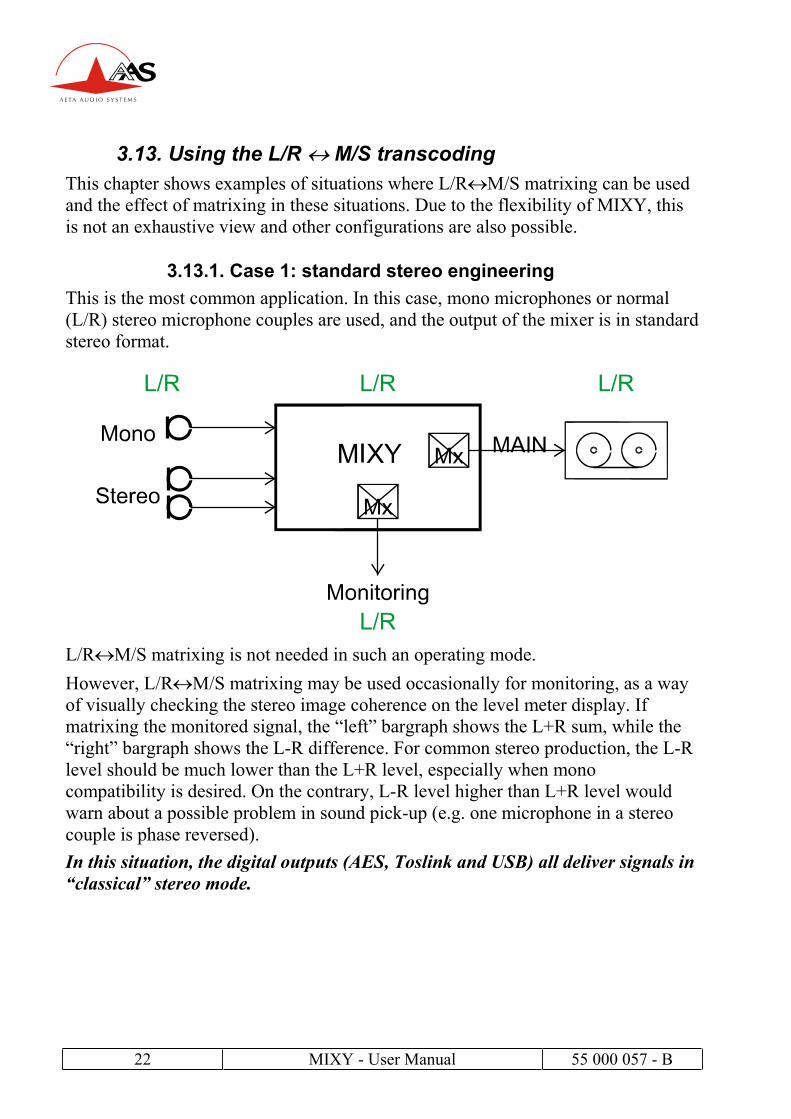
3.13.1. Case 1: standard stereo engineering
This is the most common application. In this case, mono microphones or normal
(L/R) stereo microphone couples are used, and the output of the mixer is in standard
stereo format.
L/R M/S matrixing is not needed in such an operating mode.
However, L/R M/S matrixing may be used occasionally for monitoring, as a way
of visually checking the stereo image coherence on the level meter display. If
matrixing the monitored signal, the “left” bargraph shows the L+R sum, while the
“right” bargraph shows the L-R difference. For common stereo production, the L-R
level should be much lower than the L+R level, especially when mono
compatibility is desired. On the contrary, L-R level higher than L+R level would
warn about a possible problem in sound pick-up (e.g. one microphone in a stereo
couple is phase reversed).
In this situation, the digital outputs (AES, Toslink and USB) all deliver signals in
“classical” stereo mode.

55 000 057 - B MIXY - User Manual 23
3.13.2. Case 2: stereo recording using M/S microphones
In this case, M/S stereo microphone couples are used (typically the association of a
directional cardioid transducer for the “M” channel and a bidirectional “figure of 8”
transducer for the “S” channel), but the output of the mixer is in standard stereo
format.
One way to do that is to configure inputs 1 and 2 in M/S mode, which will then feed
the mix buses in normal stereo mode, just as in the previous example.
Let us consider here an alternate way of working, where the inputs are left M/S
encoded to feed the mix buses. Instead of left and right, the mixer buses now
actually process M (Mid) and S (Side) signals. In order to output normal stereo
signals, L/R M/S matrixing must be applied at the outputs; this can be activated in
the “Outputs” sub-menu. Only the analog and USB outputs are so decoded to
normal stereo format.
Matrixing is also needed for monitoring a normal stereo signal on the headphones
(monitoring set in “M/S” position), except for monitoring the output “OUT”
because it is already decoded to L/R format.
With this arrangement, note that, unlike the analog and USB outputs, the digital outputs (AES and Toslink) stay encoded in M/S format, which allows subsequent re-
work on the stereo image in post-production.

24 MIXY - User Manual 55 000 057 - B
3.13.3. Case 3: M/S recording using M/S microphones
In this case, M/S stereo microphone couples are used, and the output is kept in M/S
format for recording. In this way, further stereo image processing is made possible
with studio equipment in later production.
The mixer buses process M (Mid) and S (Side) signals. L/R M/S matrixing is not
applied at the MAIN output (Outputs kept configured in “L/R” mode). Monitoring
is here set in “M/S” mode, as matrixing is needed for monitoring a normal stereo
signal on the headphones and meters.
55 000 057 - B MIXY - User Manual 25
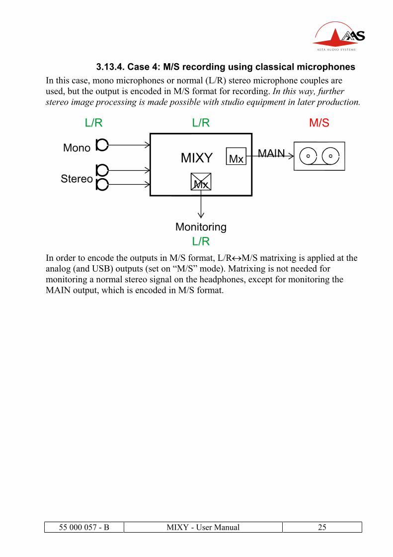
3.13.4. Case 4: M/S recording using classical microphones
In this case, mono microphones or normal (L/R) stereo microphone couples are
used, but the output is encoded in M/S format for recording. In this way, further
stereo image processing is made possible with studio equipment in later production.
In order to encode the outputs in M/S format, L/R M/S matrixing is applied at the
analog (and USB) outputs (set on “M/S” mode). Matrixing is not needed for
monitoring a normal stereo signal on the headphones, except for monitoring the
MAIN output, which is encoded in M/S format.
26 MIXY - User Manual 55 000 057 - B
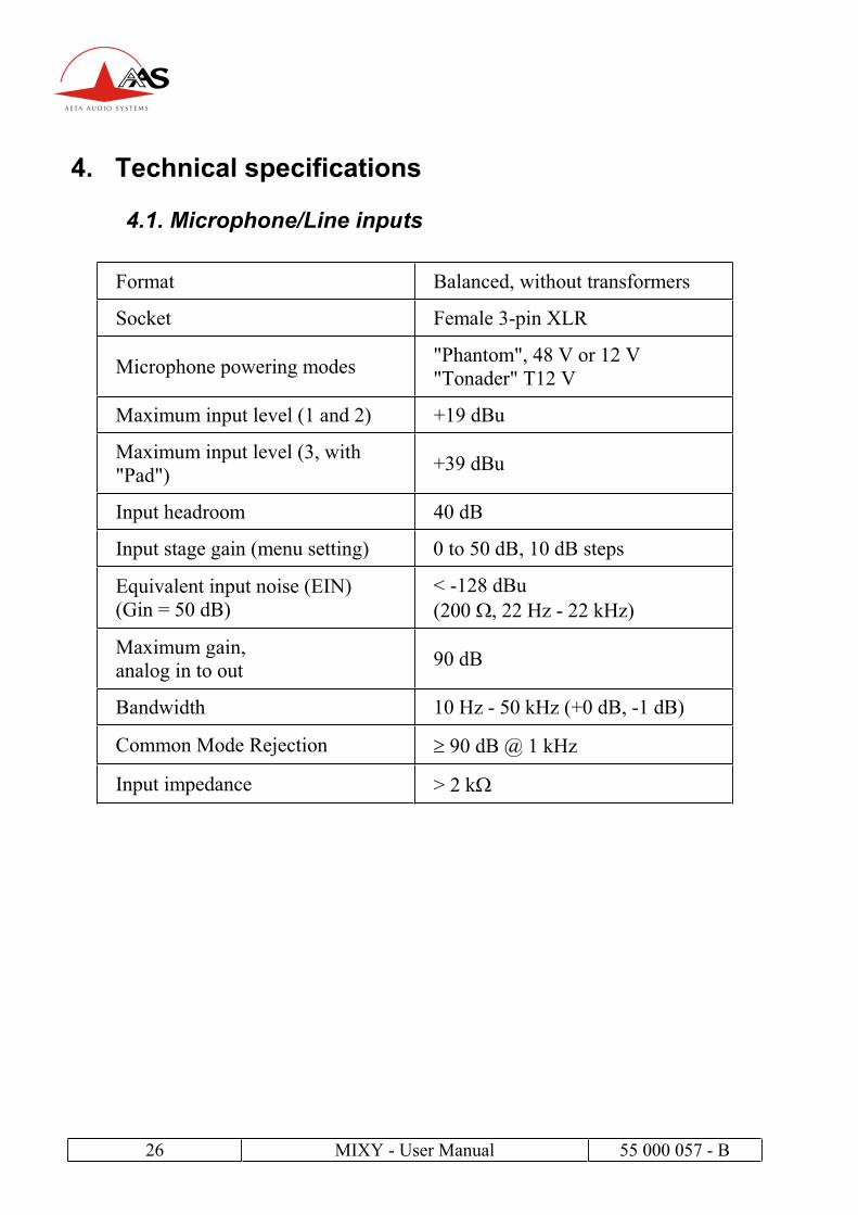
4. Technical specifications
4.1. Microphone/Line inputs
Format Balanced, without transformers
Socket Female 3-pin XLR
Microphone powering modes "Phantom", 48 V or 12 V
"Tonader" T12 V
Maximum input level (1 and 2) +19 dBu
Maximum input level (3, with
"Pad")+39 dBu
Input headroom 40 dB
Input stage gain (menu setting) 0 to 50 dB, 10 dB steps
Equivalent input noise (EIN)
(Gin = 50 dB)
< -128 dBu
(200 , 22 Hz - 22 kHz)
Maximum gain,
analog in to out 90 dB
Bandwidth 10 Hz - 50 kHz (+0 dB, -1 dB)
Common Mode Rejection 90 dB @ 1 kHz
Input impedance > 2 k
55 000 057 - B MIXY - User Manual 27
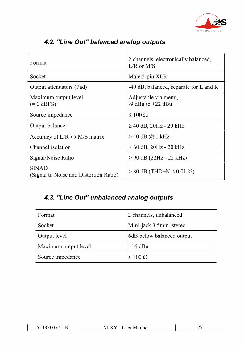
4.2. "Line Out" balanced analog outputs
Format 2 channels, electronically balanced,
L/R or M/S
Socket Male 5-pin XLR
Output attenuators (Pad) -40 dB, balanced, separate for L and R
Maximum output level
(= 0 dBFS)
Adjustable via menu,
-9 dBu to +22 dBu
Source impedance 100
Output balance 40 dB, 20Hz - 20 kHz
Accuracy of L/R M/S matrix > 40 dB @ 1 kHz
Channel isolation > 60 dB, 20Hz - 20 kHz
Signal/Noise Ratio > 90 dB (22Hz - 22 kHz)
SINAD
(Signal to Noise and Distortion Ratio) > 80 dB (THD+N < 0.01 %)
4.3. "Line Out" unbalanced analog outputs
Format 2 channels, unbalanced
Socket Mini-jack 3.5mm, stereo
Output level 6dB below balanced output
Maximum output level +16 dBu
Source impedance 100
28 MIXY - User Manual 55 000 057 - B
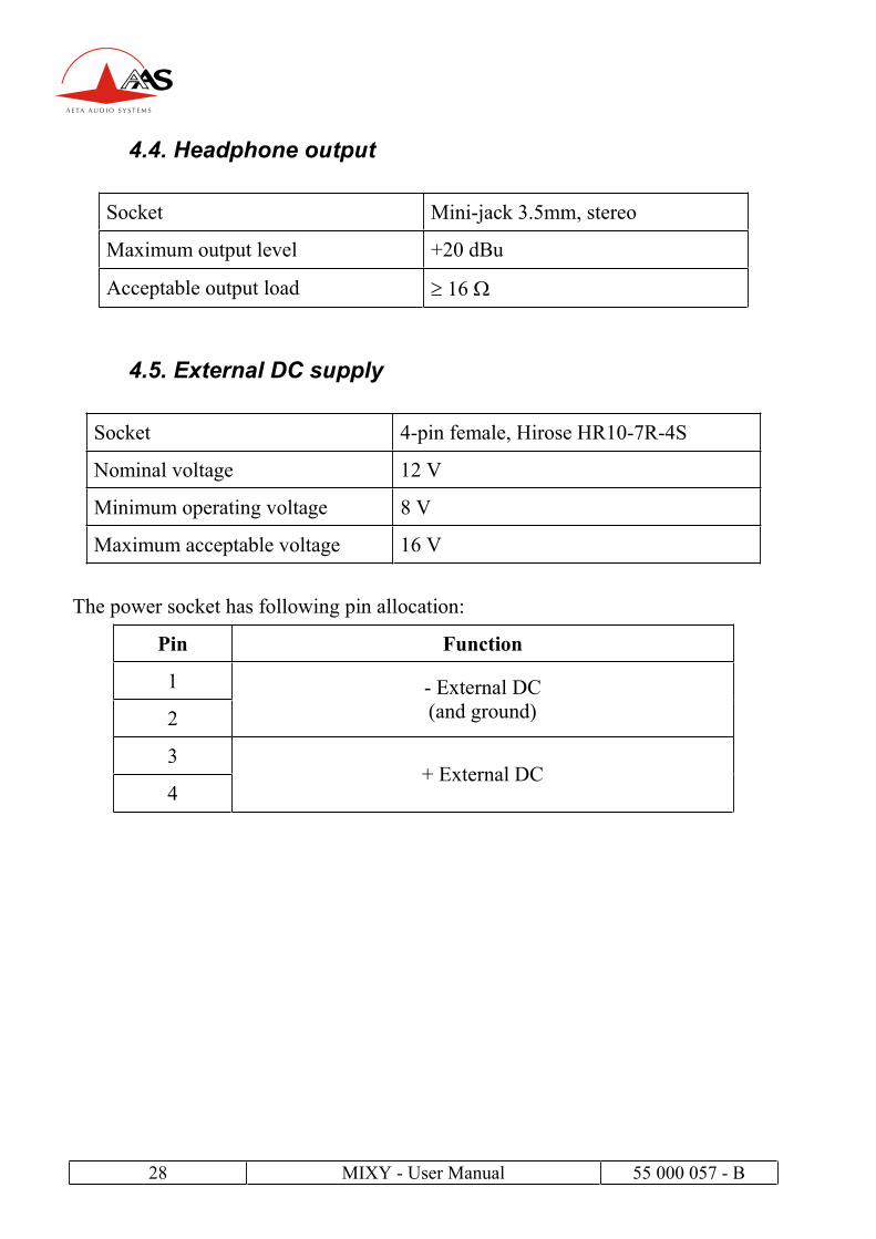
4.4. Headphone output
Socket Mini-jack 3.5mm, stereo
Maximum output level +20 dBu
Acceptable output load 16
4.5. External DC supply
Socket 4-pin female, Hirose HR10-7R-4S
Nominal voltage 12 V
Minimum operating voltage 8 V
Maximum acceptable voltage 16 V
The power socket has following pin allocation:
Pin Function
1
2
- External DC
(and ground)
3
4+ External DC
55 000 057 - B MIXY - User Manual 29
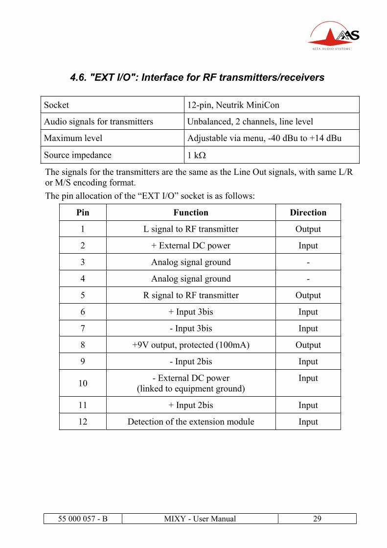
4.6. "EXT I/O": Interface for RF transmitters/receivers
Socket 12-pin, Neutrik MiniCon
Audio signals for transmitters Unbalanced, 2 channels, line level
Maximum level Adjustable via menu, -40 dBu to +14 dBu
Source impedance 1 k
The signals for the transmitters are the same as the Line Out signals, with same L/R
or M/S encoding format.
The pin allocation of the “EXT I/O” socket is as follows:
Pin Function Direction
1 L signal to RF transmitter Output
2 + External DC power Input
3 Analog signal ground -
4 Analog signal ground -
5 R signal to RF transmitter Output
6 + Input 3bis Input
7 - Input 3bis Input
8 +9V output, protected (100mA) Output
9 - Input 2bis Input
10- External DC power
(linked to equipment ground)
Input
11 + Input 2bis Input
12 Detection of the extension module Input

30 MIXY - User Manual 55 000 057 - B
4.7. Digital outputs and direct analog outputs
A common socket groups the two-channel digital audio output and three direct
analog outputs (direct channel signals, pre-fader).
The pin assignment of this 6-pin Hirose HR10-7R-6S is the following:
The differential signal on pins 2 and 3 has an AES format (110 impedance) and
following characteristics:
Standard AES3 (Professional)
Format Balanced, transformer isolated
Amplitude (on 110 load) 4 V p-p
Source impedance 110
An optional adaptation cable provides the AES signal on a 3-pin male XLR plug.
As an alternate option, an SPDIF adaptation cable is available; it provides the signal
on an RCA plug with following characteristics:
Standard CEI 958 , SPDIF, "consumer" format
Electrical format Unbalanced, transformer isolated
Connector Male RCA plug
Amplitude (on 75 load) 0.5V c-c
Source impedance 75
Pin Function
1 Direct output of channel 1, pre-fader
2 + AES digital output
3 - AES digital output
4 Direct output of channel 2, pre-fader
5 Analog signal ground
6 Direct output of channel 3, pre-fader

55 000 057 - B MIXY - User Manual 31
4.8. Power supply
MIXY operates from its internal 4-element NiMH battery, or from a DC external
voltage source. MIXY automatically and seamlessly switches between these power
sources, with priority given to the external DC source.
This external source may be a power adapter delivering a filtered DC voltage (8 V
minimum) or an external battery (like e.g. an NP1 battery pack).
An icon on the display shows the battery level:
5 segments = 5.6V (full charge)
4 segments = 5.1V
3 segments = 4.8V
2 segments = 4.4V
1 segment = 4.2V (should be recharged shortly)
Whenever the battery voltage goes down to 4 V (1 V per internal element),
MIXY is automatically shut off. This prevents damaging the battery by
discharging it too deeply. Conversely, it will only be possible to restart MIXY from
its internal battery after it has been recharged to at least 4.5 V.
It is thus highly recommended to recharge the unit if only one segment has been displayed for half an hour or more!
MIXY’s power consumption and hence its battery range depend much on the
operating conditions, such as the number and powering mode of the microphones,
headphone impedance and listening level, etc.
However, as an example, starting with a full charged battery, MIXY will operate for
at least 12 hours with dynamic microphones (including ribbon microphones) and a
600 headphone. In such condition, MIXY draws less than 1500 mA from a
14.4 V external source.
MIXY draws a near-constant power (not a constant current) from the external
source when the voltage varies.
32 MIXY - User Manual 55 000 057 - B
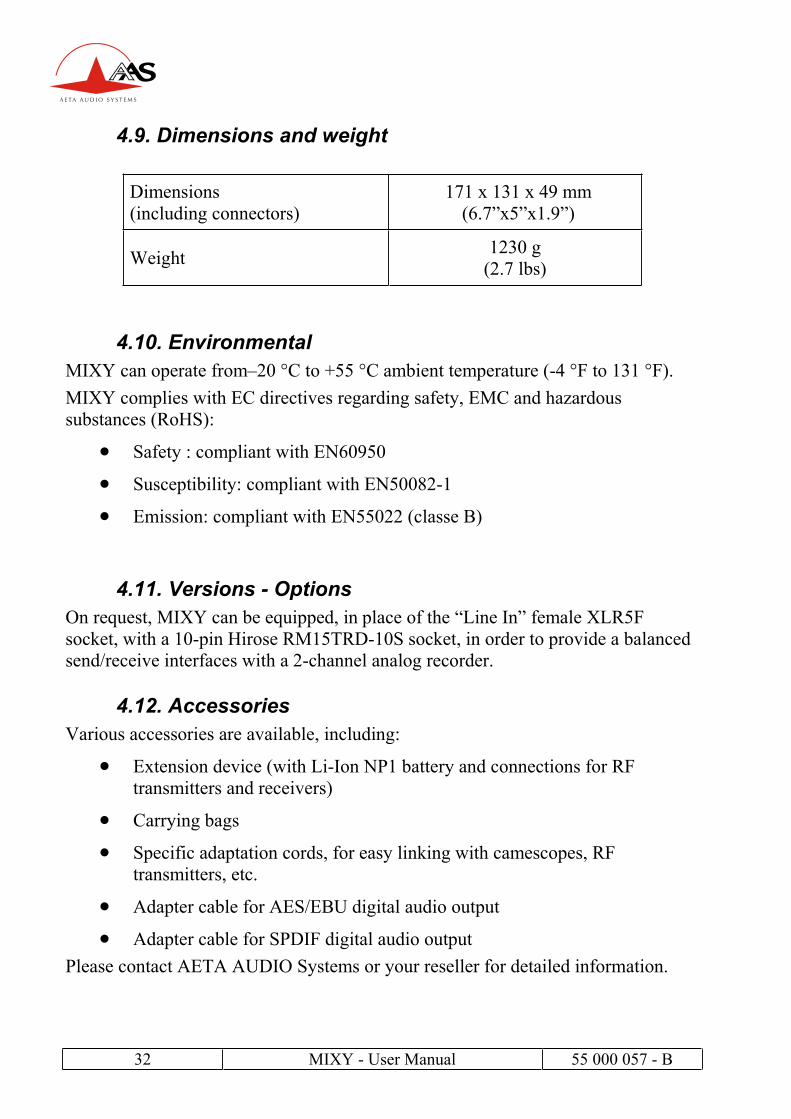
4.9. Dimensions and weight
Dimensions
(including connectors)
171 x 131 x 49 mm
(6.7”x5”x1.9”)
Weight 1230 g
(2.7 lbs)
4.10. Environmental
MIXY can operate from–20 °C to +55 °C ambient temperature (-4 °F to 131 °F).
MIXY complies with EC directives regarding safety, EMC and hazardous
substances (RoHS):
Safety : compliant with EN60950
Susceptibility: compliant with EN50082-1
Emission: compliant with EN55022 (classe B)
4.11. Versions - Options
On request, MIXY can be equipped, in place of the “Line In” female XLR5F
socket, with a 10-pin Hirose RM15TRD-10S socket, in order to provide a balanced
send/receive interfaces with a 2-channel analog recorder.
4.12. Accessories
Various accessories are available, including:
Extension device (with Li-Ion NP1 battery and connections for RF
transmitters and receivers)
Carrying bags
Specific adaptation cords, for easy linking with camescopes, RF
transmitters, etc.
Adapter cable for AES/EBU digital audio output
Adapter cable for SPDIF digital audio output
Please contact AETA AUDIO Systems or your reseller for detailed information.
55 000 057 - B MIXY - User Manual 33
5. Annexes
5.1. General block diagram
15/120/300Hz
Ch2
Ch1
IN1
IN2
IN3
RTN1
USBR
USBL
OUTR
OUTL
RTN2
Ch3
Lim
OVLD
BUS
LR
A
A
1 2
Ext.I/O
Ext.I/O
3
LineIn
8-18V
DC
LineOut
OpticalOut
SPDIF
In
USB
Direct
&Dig.Out
PAD
20dB
PAD
40dB
PAD
40dB
Rx2
Tx2
Rx1
Tx1
SYNC
On/O
ff
OUT
BUS
RTN
IN1
IN1
IN2
IN2
IN3
IN3
USB
0/+
20dB
L/R/C
L/R/C
L/R/C
L/R/C
L/R/C
P12
P48
T12
Off
P12
P48
T12
Off
P12
P48
T12
Off
DC
Ch1..3
HPF
USB
Interface
M/S
dec
M/S
dec
Balance
/Swidth
L/C/R
Routing
L/C/R
Routing
Slate
Mic
power
0..50dB
(10dBsteps)
Coupling
(Stereo/M
S)
Charger
Differential
signal
2channel
audio
signal
Monitoring
point
Monitor
Source
Select
Monitor
Mode
Select
Meter
int/det
D
D
Tone
ToslinkI/F Digital
Audio
Tx
Digital
Audio
Rx
Route
Invert
34 MIXY - User Manual 55 000 057 - B
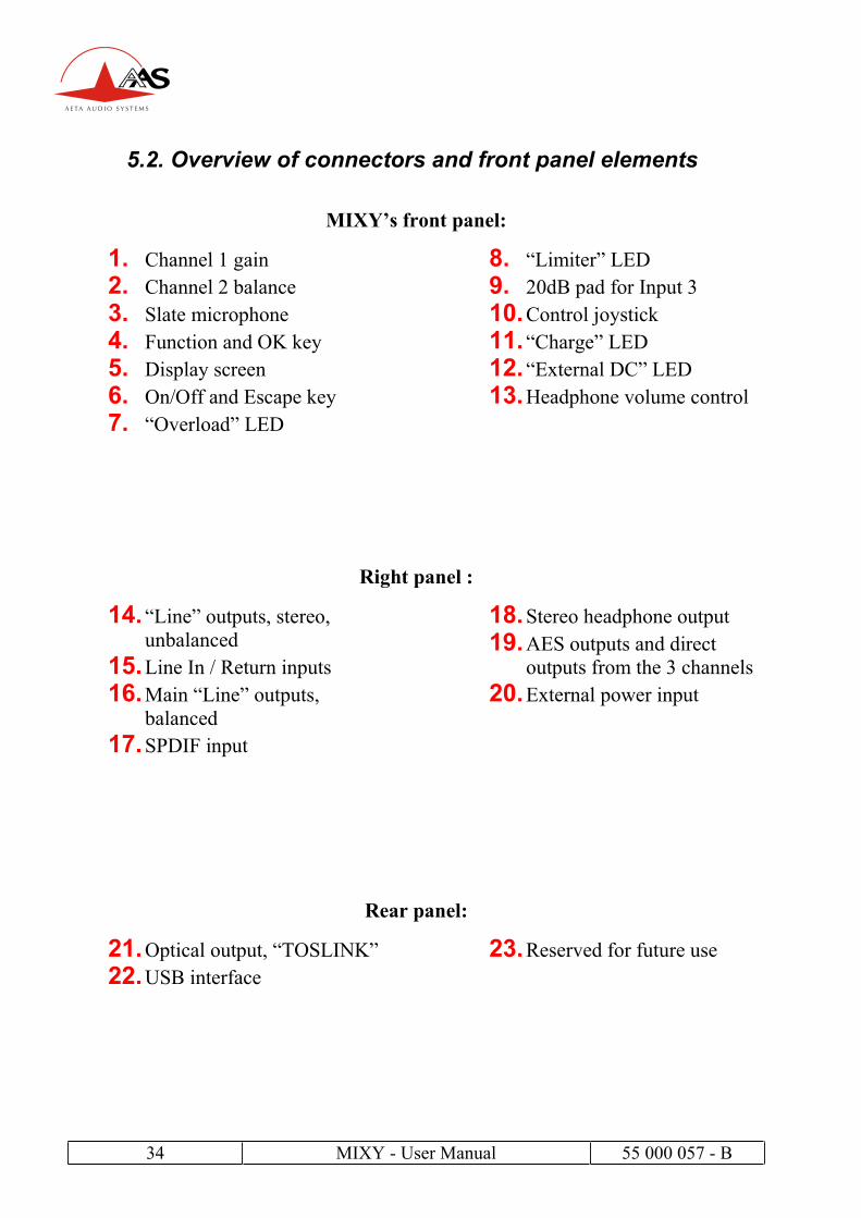
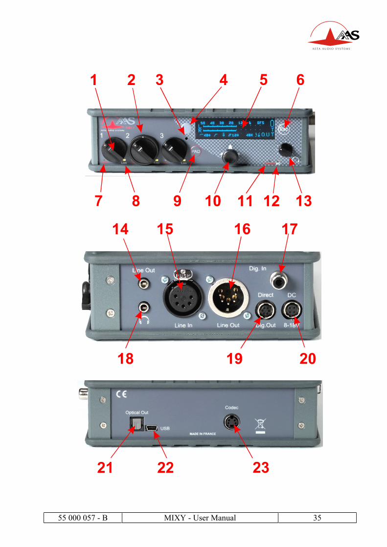
5.2. Overview of connectors and front panel elements
MIXY’s front panel:
1. Channel 1 gain
2. Channel 2 balance
3. Slate microphone
4. Function and OK key
5. Display screen
6. On/Off and Escape key
7. “Overload” LED
8. “Limiter” LED
9. 20dB pad for Input 3
10.Control joystick
11.“Charge” LED
12.“External DC” LED
13.Headphone volume control
Right panel :
14.“Line” outputs, stereo,
unbalanced
15.Line In / Return inputs
16.Main “Line” outputs,
balanced
17.SPDIF input
18.Stereo headphone output
19.AES outputs and direct
outputs from the 3 channels
20.External power input
Rear panel:
21.Optical output, “TOSLINK”
22.USB interface
23.Reserved for future use
55 000 057 - B MIXY - User Manual 35

36 MIXY - User Manual 55 000 057 - B
5.3. Level maps
Mic/Line input level map
+19 +19 +19
-18 -18 -18
+19
+2
-18
-86-86
-128 -128
-98 -98
-106 -106 -106
-88
+39
0
-18-18-18
-36-36
-24
-42-36-36
-86
-18
-36
-36-36
-130
-120
-110
-100
-90
-80
-70
-60
-50
-40
-30
-20
-10
0
+10
+20
+30
+40
Input
PAD
(Input 3) Preamp
HPF &
Direct out Fader Limiter
M/S
decode
Bus=> Digital
(dBFS)dBu
Max output level
Std output level (-18 dBFS)Min gain
Max gain
PAD on
PAD on
Noise floor (minimum gain, fader low)
M/S decoder
active
Max input level
Line output level map
0
+16
+22
+16
+4
-27
-67
0
-6
+10
-2
-33
-18
-18
-70
-60
-50
-40
-30
-20
-10
0
+10
+20
+30
Digital
(dBFS) Matrixing
Unbalanced
Out Line outdBu
Max. gain
(setting +22 dBu)
Min. gain
(setting -9 dBu)
M/S matrixing
Max level
Std level
PAD on