Embed Size (px)
Citation preview

Instructions
Portable Surface Roughness Gages
Pocket Surf® IV
2
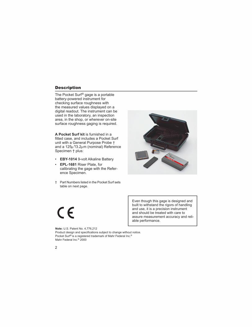
The Pocket Surf ® gage is a portable battery-powered instrument for checking surface roughness with the measured values displayed on a digital readout. The instrument can be used in the laboratory, an inspection area, in the shop, or wherever on-site surface roughness gaging is required.
A Pocket Surf kit is furnished in a
unit with a General Purpose Probe † and a 125 "/3.2 m (nominal) Reference Specimen † plus:
EBY-1014 9-volt Alkaline Battery
EPL-1681 Riser Plate, for calibrating the gage with the Refer-ence Specimen.
† Part Numbers listed in the Pocket Surf sets
table on next page.
Description
Even though this gage is designed and built to withstand the rigors of handling and use, it is a precision instrument and should be treated with care to assure measurement accuracy and reli-able performance.
Note: U.S. Patent No. 4,776,212
Pocket Surf® is a registered trademark of Mahr Federal Inc.®
Mahr Federal Inc.® 2000
3
Measuring Ranges. . . . . . . . . . . . . . Ra — 1 " to 250 "/0.03 m to 6.35 m
Ry — 8 " to 999 "/0.2 m to 25.3 m
Rmax — 8 " to 999 "/0.2 m to 25.3 m
Rz — 8 " to 999 "/0.2 m to 25.3 m
Display Resolution . . . . . . . . . . . . . . 1 "/0.01 m
Measurement Accuracy . . . . . . . . . Meets ASME B46.1, ISO and DIN
standards
Digital Readout . . . . . . . . . . . . . . . . . 3-digit LCD display, with “Battery” icon
Traverse Length (Selectable) . . . . . . See table on page 9.
Evaluation Length (Selectable) . . . . See table on page 9.
Traverse Speed . . . . . . . . . . . . . . . . .2"/5.08mm per second
Cutoff . . . . . . . . . . . . . . . . . . . . . . . . .
Probe Type . . . . . . . . . . . . . . . . . . . . Piezoelectric
Maximum Stylus Force
(within displacement range) . . . . . . . 1500mgf/15.0mN
Power . . . . . . . . . . . . . . . . . . . . . . . . . 9-volt consumer-type alkaline battery
Battery Capacity . . . . . . . . . . . . . . . Approx. 2500 measurements, depending
on frequency/degree of usage
Operating Temperature . . . . . . . . . . 50° to 113°F/10° to 45°C
Storage Temperature . . . . . . . . . . . – 4° to 149°F/-20° to 65°C
Pocket Surf Sets
Order no.
2191800 EGH-1019 Probe, 90°, 10 µm radius, PMD-90101,
2191802 EGH-1026 Probe, 90°, 5 µm radius, PMD-90101,
4
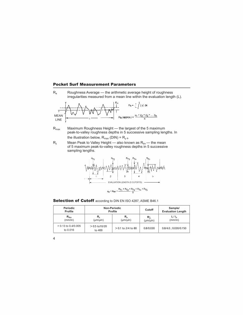
Ra Roughness Average — the arithmetic average height of roughness
irregularities measured from a mean line within the evaluation length (L).
Rmax Maximum Roughness Height — the largest of the 5 maximum peak-to-valley roughness depths in 5 successive sampling lengths. In
the illustration below, Rmax (DIN) = Ry 4.
Rz Mean Peak to Valley Height — also known as Rtm — the mean of 5 maximum peak-to-valley roughness depths in 5 successive sampling lengths.
MEAN
LINE
EVALUATION LENGTH (5 CUTOFFS)
Periodic Non-Periodic Cutoff
RSm
(mm/in)
Rz
(µm/µin)
Ra
(µm/µin)R
(µm/µin)
Ir n
(mm/in)
> 0.13 to 0.4/0.005
to 0.016
> 0.5 to10/20
to 400> 0.1 to 2/4 to 80 0.8/0.030 0.8/4.0 ; 0.030/0.150
Selection of Cutoff according to DIN EN ISO 4287, ASME B46.1
5
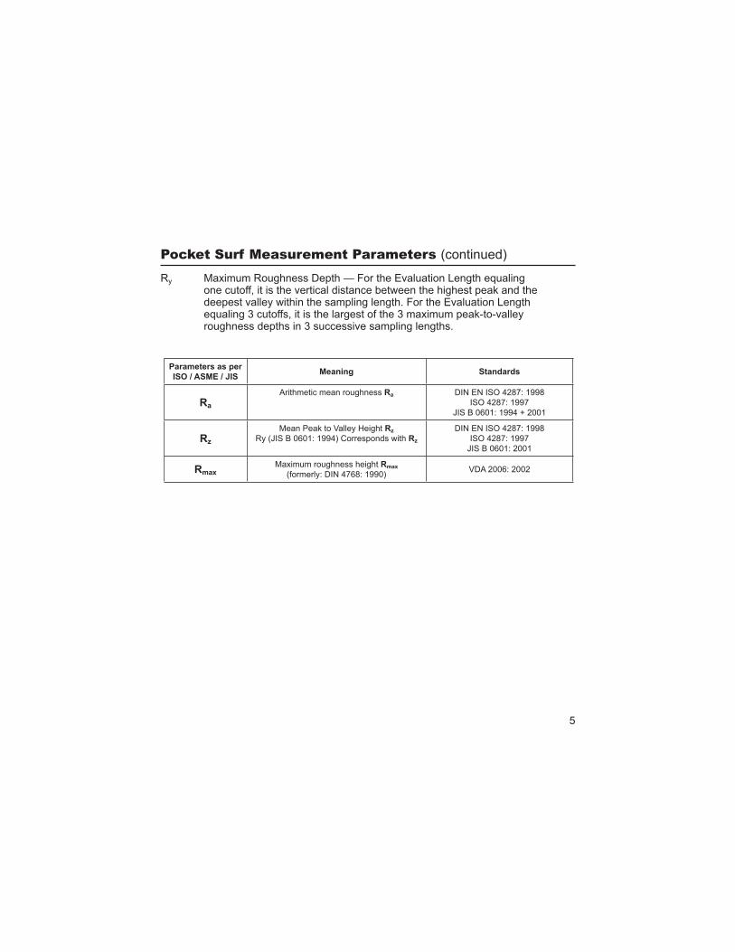
Ry Maximum Roughness Depth — For the Evaluation Length equaling one cutoff, it is the vertical distance between the highest peak and the deepest valley within the sampling length. For the Evaluation Length equaling 3 cutoffs, it is the largest of the 3 maximum peak-to-valley roughness depths in 3 successive sampling lengths.
(continued)
Parameters as per Standards
Ra
Arithmetic mean roughness Ra DIN EN ISO 4287: 1998
ISO 4287: 1997
JIS B 0601: 1994 + 2001
Rz
Mean Peak to Valley Height Rz
Ry (JIS B 0601: 1994) Corresponds with Rz
DIN EN ISO 4287: 1998
ISO 4287: 1997
JIS B 0601: 2001
RmaxMaximum roughness height Rmax
(formerly: DIN 4768: 1990)VDA 2006: 2002
6
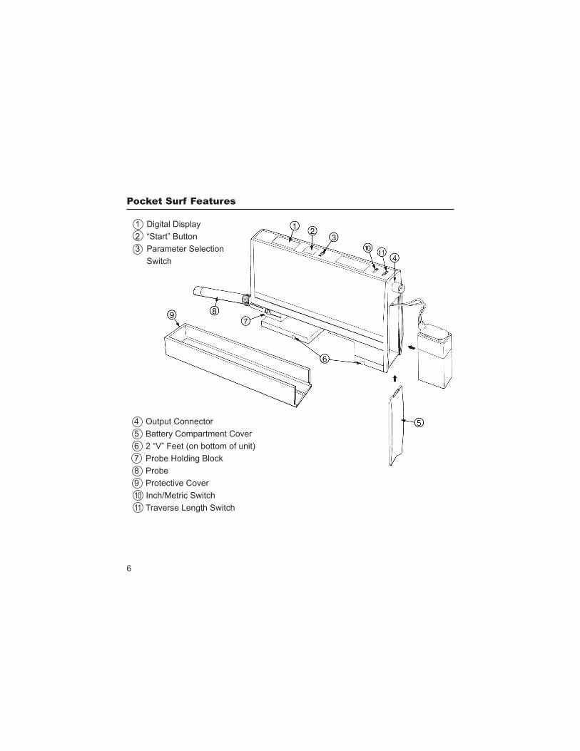
1 Digital Display
2 “Start” Button
3 Parameter Selection
Switch
4 Output Connector
5 Battery Compartment Cover
6 2 “V” Feet (on bottom of unit)
7 Probe Holding Block
8 Probe
9 Protective Cover
10 Inch/Metric Switch
11 Traverse Length Switch
7
)
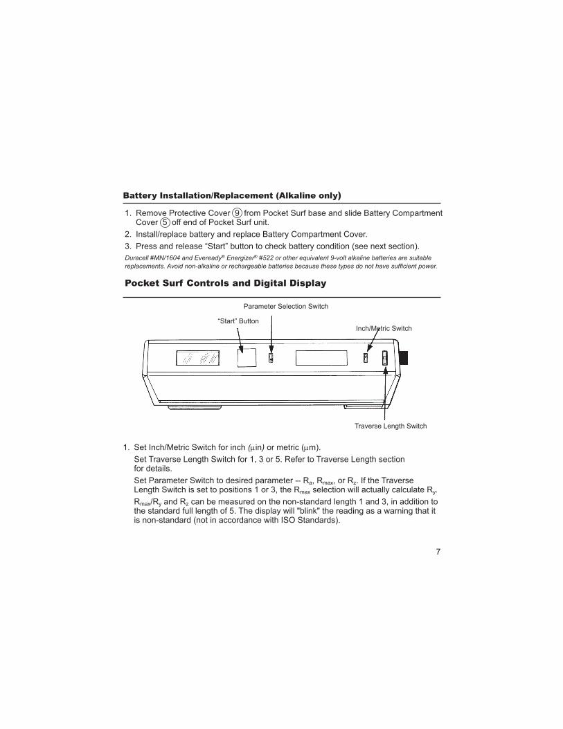
1. Set Inch/Metric Switch for inch ( in) or metric ( m).
Set Traverse Length Switch for 1, 3 or 5. Refer to Traverse Length section for details.
Set Parameter Switch to desired parameter -- Ra, Rmax, or Rz. If the Traverse Length Switch is set to positions 1 or 3, the Rmax selection will actually calculate Ry.
Rmax/Ry and Rz can be measured on the non-standard length 1 and 3, in addition to the standard full length of 5. The display will "blink" the reading as a warning that it is non-standard (not in accordance with ISO Standards).
Parameter Selection Switch
Inch/Metric Switch
Traverse Length Switch
“Start” Button
1. Remove Protective Cover 9 from Pocket Surf base and slide Battery Compartment Cover 5 off end of Pocket Surf unit.
2. Install/replace battery and replace Battery Compartment Cover.
3. Press and release “Start” button to check battery condition (see next section).
Duracell #MN/1604 and Eveready® Energizer® #522 or other equivalent 9-volt alkaline batteries are suitable
8
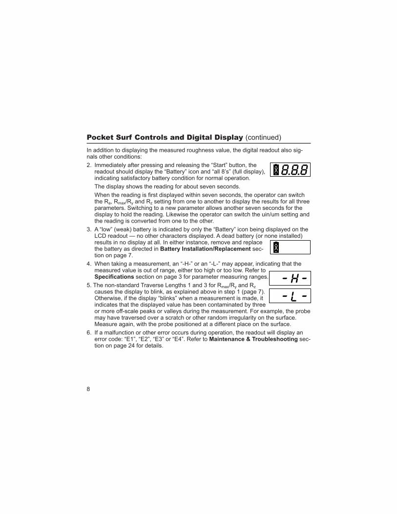
In addition to displaying the measured roughness value, the digital readout also sig-nals other conditions:
2. Immediately after pressing and releasing the “Start” button, the readout should display the “Battery” icon and “all 8’s” (full display), indicating satisfactory battery condition for normal operation.
The display shows the reading for about seven seconds.
the Ra, Rmax/Ry and Rz setting from one to another to display the results for all three parameters. Switching to a new parameter allows another seven seconds for the display to hold the reading. Likewise the operator can switch the uin/um setting and the reading is converted from one to the other.
3. A “low” (weak) battery is indicated by only the “Battery” icon being displayed on the LCD readout — no other characters displayed. A dead battery (or none installed) results in no display at all. In either instance, remove and replace the battery as directed in sec-tion on page 7.
4. When taking a measurement, an “-H-” or an “-L-” may appear, indicating that the measured value is out of range, either too high or too low. Refer to
section on page 3 for parameter measuring ranges.
5. The non-standard Traverse Lengths 1 and 3 for Rmax/Ry and Rz causes the display to blink, as explained above in step 1 (page 7). Otherwise, if the display “blinks” when a measurement is made, it indicates that the displayed value has been contaminated by three or more off-scale peaks or valleys during the measurement. For example, the probe may have traversed over a scratch or other random irregularity on the surface. Measure again, with the probe positioned at a different place on the surface.
6. If a malfunction or other error occurs during operation, the readout will display an error code: “E1”, “E2”, “E3” or “E4”. Refer to sec-tion on page 24 for details.
(continued)
9
There are three traverse lengths available. For measuring short surfaces such as o-ring grooves, short lands and shoulders, use Switch Positions 1 or 3.
.075"/2.0mm .030"/0.8mm 1 .135"/3.5mm .090"/2.4mm 3 .195"/5.0mm .150"/4.0mm 5
Cutoff equals .030"/0.8mm.
The Pocket Surf gage will operate in any one of four different probe positions (see illustration on next page). Selection of the proper probe position depends on the ap-plication.
When changing probe positions, gently grasp the probe by its body; never handle the probe by its skid and stylus end.
Prior to operating the gage, its calibration should be checked. Refer to the section for details.
Important: During the measuring cycle, the probe stylus and skid should be in contact with a surface, and the setup should be properly aligned (as outlined in the following sections). Otherwise, any readings obtained are not valid and are not to be used for measurement or gage performance evaluation purposes.
10
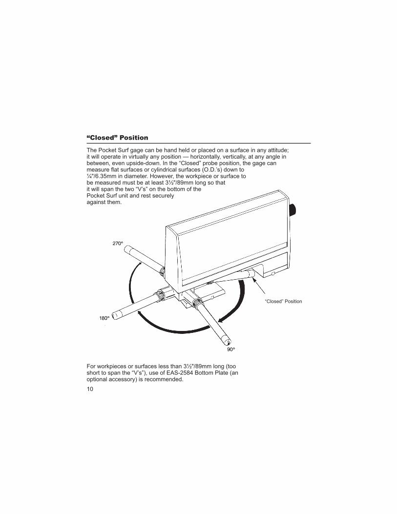
The Pocket Surf gage can be hand held or placed on a surface in any attitude; it will operate in virtually any position — horizontally, vertically, at any angle in between, even upside-down. In the “Closed” probe position, the gage can
¼"/6.35mm in diameter. However, the workpiece or surface to be measured must be at least 3½"/89mm long so that it will span the two “V’s” on the bottom of the Pocket Surf unit and rest securely against them.
For workpieces or surfaces less than 3½"/89mm long (too short to span the “V’s”), use of EAS-2584 Bottom Plate (an optional accessory) is recommended.
“Closed” Position
11
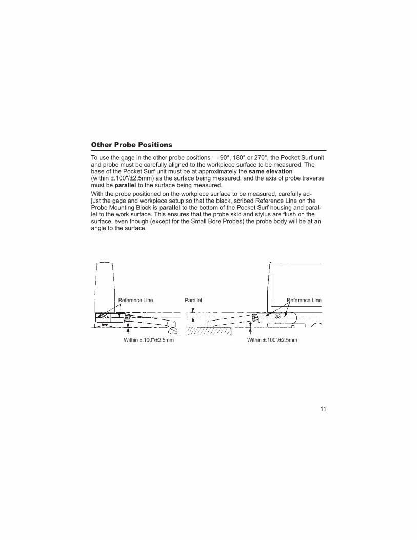
To use the gage in the other probe positions — 90°, 180° or 270°, the Pocket Surf unit and probe must be carefully aligned to the workpiece surface to be measured. The base of the Pocket Surf unit must be at approximately the (within ±.100"/±2,5mm) as the surface being measured, and the axis of probe traverse must be to the surface being measured.
With the probe positioned on the workpiece surface to be measured, carefully ad- the gage and workpiece setup so that the black, scribed Reference Line on the
Probe Mounting Block is to the bottom of the Pocket Surf housing and paral-
surface, even though (except for the Small Bore Probes) the probe body will be at an angle to the surface.
Parallel Reference LineReference Line
Within ±.100"/±2.5mmWithin ±.100"/±2.5mm
12
In the 180° “Extended” position, the
surfaces, large cylindrical or O.D. surfaces and inside diameters. Because there is some leeway permitted in the elevation between the base of the Pocket Surf unit and the surface to be measured, the gage can be used to measure sur-faces that are raised slightly above or recessed slightly below (within
Be sure the two “V’s” on the bottom of
Inside diameters larger than 1.1"/28.0mm may be measured up to a depth (in-reach) of 2.0"/50mm using a General Purpose Probe. For smaller inside diameters down to 1/8"/3.2mm an optional Small Bore Probe is required. For most I.D. measurements, the Pocket Surf unit cannot be hand held; it must be mounted on a stand such as the optional EAS-2426 Universal Stand or EAS-2496 Height Stand. Refer to
section for ad-ditional information.
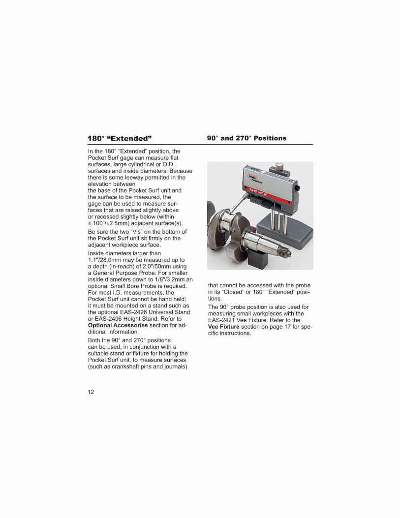
Both the 90° and 270° positions
Pocket Surf unit, to measure surfaces
that cannot be accessed with the probe in its “Closed” or 180° “Extended” posi-tions.
The 90° probe position is also used for measuring small workpieces with the EAS-2421 Vee Fixture. Refer to the Vee Fixture section on page 17 for spe-
13
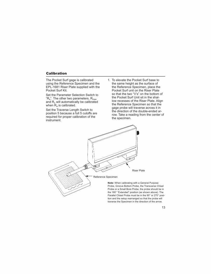
The Pocket Surf gage is calibrated using the Reference Specimen and the EPL-1681 Riser Plate supplied with the Pocket Surf Kit.
Set the Parameter Selection Switch to “Ra”. The other two parameters, Rmax
and Rz will automatically be calibrated when Ra is calibrated.
Set the Traverse Length Switch to position 5 because a full 5 cutoffs are required for proper calibration of the instrument.
Note: When calibrating with a General Purpose
Probe, Groove Bottom Probe, the Transverse Chisel
Probe or a Small Bore Probe, the probe should be in
the 180° “Extended” position (as shown above). The
Parallel Chisel Probe must be in the 90° or 270° posi-
tion and the setup rearranged so that the probe will
traverse the Specimen in the direction of the arrow.
1. To elevate the Pocket Surf base to the same height as the surface of the Reference Specimen, place the Pocket Surf unit on the Riser Plate so that the two “V’s” on the bottom of the Pocket Surf Unit sit in the shal-low recesses of the Riser Plate. Align the Reference Specimen so that the gage probe will traverse across it in the direction of the double-ended ar-row. Take a reading from the center of the specimen.
Riser Plate
Reference Specimen
14
(continued)
If the reading is within ±4 in/±0.1 m of the value stated on the label on the bottom of the specimen*, calibration Is within tolerance.
If the reading differs from the value stated on the label (or on a Report
than ±4 in/±0.1 m, take additional readings around the central area of the Reference Specimen. If the readings still differ by more than the allowable tolerance, recalibrate the Pocket Surf unit following the procedure below.
2. Take a measurement on the Refer-ence Specimen. While there is a measurement on the display go to Step 3 below. The display remains visible for about 7 seconds. Be sure to proceed from Steps 2 through 6 within seven seconds during each step or you will have to begin again from Step 2 should the display go blank.
3. Press and hold the Start Button for three seconds until the letters CAL appear.
while CAL is shown on the display.
5. Press the Start Button again to enter the assessed value found on the
-ence Specimen. Or, enter the value found on the back of the reference
specimen. Continue pressing the Start Button to change the number in the display until the same number as the assessed value appears. The values can range from 106µin/2.69µm through 135µin/3.43µm. Select the closest value to the assessed value of the Reference Specimen.
6. After the correct value appears, press and hold the Start Button for three seconds to lock-in the assessed value.
times and disappears, release the Start Button. The Pocket Surf® IV is now calibrated.
7. Finally, run a test of the Reference Specimen.
To check the condition of the probe stylus, a “double patch” Reference Specimen (optionally available) is rec-ommended. A “double patch” Specimen can also be used for calibration of the gage; however,
. Be careful not to use the other section of the “double patch” Specimen for calibration as it could introduce seri-ous errors into the gage’s roughness readings. The 20 in/0.5 section is only to be used for checking probe stylus condition.
* -
15
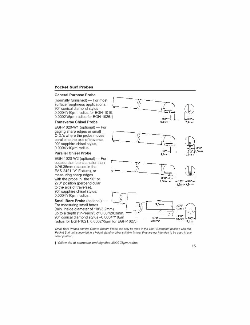
(normally furnished) — For most surface roughness applications. 90° conical diamond stylus – 0.0004"/10 m radius for EGH-1019, 0.0002"/5 m radius for EGH-1026.†
EGH-1020-W1 (optional) — For gaging sharp edges or small O.D.’s where the probe moves parallel to the axis of traverse. 90° sapphire chisel stylus, 0.0004"/10 m radius.
EGH-1020-W2 (optional) — For outside diameters smaller than ¼"/6.35mm (placed in the EAS-2421 “V” Fixture), or measuring sharp edges with the probe in the 90° or 270° position (perpendicular to the axis of traverse). 90° sapphire chisel stylus, 0.0004"/10 m radius.
(optional) — For measuring small bores (min. inside diameter of 1/8"/3.2mm) up to a depth (“in-reach”) of 0.80"/20.3mm. 90° conical diamond stylus –0.0004"/10 m radius for EGH-1021, 0.0002"/5 m for EGH-1027.†
other position.
† µm radius.
16
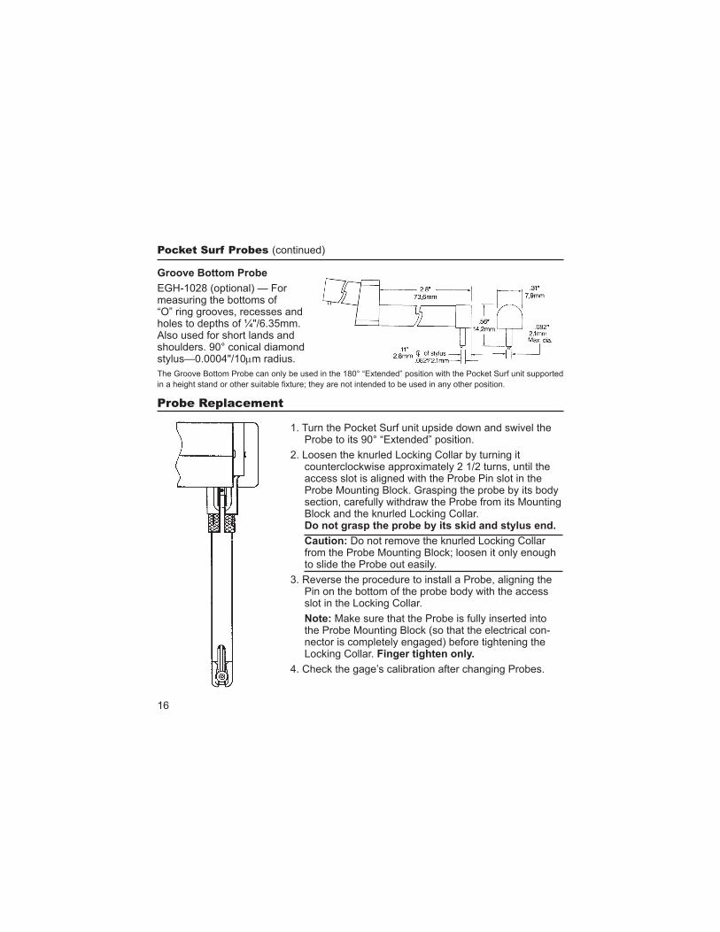
EGH-1028 (optional) — For measuring the bottoms of “O” ring grooves, recesses and holes to depths of ¼"/6.35mm. Also used for short lands and shoulders. 90° conical diamond stylus—0.0004"/10 m radius.
The Groove Bottom Probe can only be used in the 180° “Extended” position with the Pocket Surf unit supported
(continued)
1. Turn the Pocket Surf unit upside down and swivel the Probe to its 90° “Extended” position.
2. Loosen the knurled Locking Collar by turning it counterclockwise approximately 2 1/2 turns, until the access slot is aligned with the Probe Pin slot in the Probe Mounting Block. Grasping the probe by its body section, carefully withdraw the Probe from its Mounting Block and the knurled Locking Collar.
Caution: Do not remove the knurled Locking Collar from the Probe Mounting Block; loosen it only enough to slide the Probe out easily.
3. Reverse the procedure to install a Probe, aligning the Pin on the bottom of the probe body with the access slot in the Locking Collar.
Note: Make sure that the Probe is fully inserted into the Probe Mounting Block (so that the electrical con-nector is completely engaged) before tightening the Locking Collar.
4. Check the gage’s calibration after changing Probes.
17
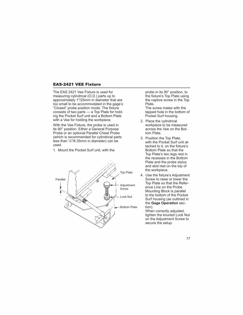
The EAS 2421 Vee Fixture is used for measuring cylindrical (O.D.) parts up to approximately 1"/25mm in diameter that are too small to be accommodated in the gage’s
consists of two parts — a Top Plate for hold-ing the Pocket Surf unit and a Bottom Plate with a Vee for holding the workpiece.
With the Vee Fixture, the probe is used in its 90° position. Either a General Purpose Probe or an optional Parallel Chisel Probe (which is recommended for cylindrical parts less than ¼"/6.35mm in diameter) can be used.
1. Mount the Pocket Surf unit, with the
probe in its 90° position, to
the captive screw in the Top Plate. The screw mates with the tapped hole in the bottom of Pocket Surf housing.
2. Place the cylindrical workpiece to be measured across the Vee on the Bot-tom Plate.
3. Position the Top Plate, with the Pocket Surf unit at-
Bottom Plate so that the Top Plate’s two legs rest in the recesses in the Bottom Plate and the probe stylus and skid rest on the top of the workpiece.
Screw to raise or lower the Top Plate so that the Refer-ence Line on the Probe Mounting Block is parallel to the bottom of the Pocket Surf housing (as outlined in the sec-tion).
tighten the knurled Lock Nut
secure the setup.
Parallel
Top Plate
Lock Nut
Bottom Plate
Screw
18
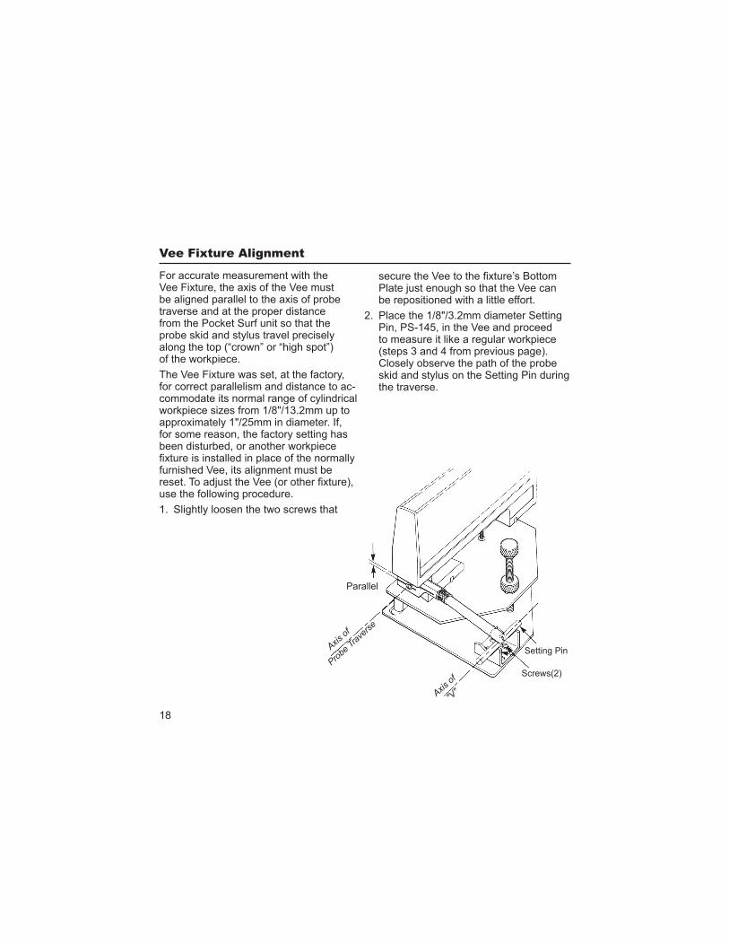
For accurate measurement with the Vee Fixture, the axis of the Vee must be aligned parallel to the axis of probe traverse and at the proper distance from the Pocket Surf unit so that the probe skid and stylus travel precisely along the top (“crown” or “high spot”) of the workpiece.
The Vee Fixture was set, at the factory, for correct parallelism and distance to ac-commodate its normal range of cylindrical workpiece sizes from 1/8"/13.2mm up to approximately 1"/25mm in diameter. If, for some reason, the factory setting has been disturbed, or another workpiece
furnished Vee, its alignment must be
use the following procedure.
1. Slightly loosen the two screws that
be repositioned with a little effort.
2. Place the 1/8"/3.2mm diameter Setting Pin, PS-145, in the Vee and proceed to measure it like a regular workpiece (steps 3 and 4 from previous page). Closely observe the path of the probe skid and stylus on the Setting Pin during the traverse.
Parallel
Setting Pin
Screws(2)
"V"
19
the Vee so that the probe skid and stylus travel precisely along the top (“crown” or “high spot”) of the Setting Pin throughout the en-tire traverse (measurement stroke). Make several passes to ensure that
that the probe skid and stylus do not wander off the top of the Setting Pin during the traverse.
4. Once the Vee is properly
(with the Pocket Surf unit on it) from the Bottom Plate, and remove the Setting Pin from the Vee. Securely tighten the two screws in the bottom of the Vee. Be very careful not to disturb the position of the Vee in performing this step.
(continued)
5. Place the Setting Pin back in the Vee and place the Top Plate (with the Pocket Surf unit) back on the Bottom Plate, with the probe skid and stylus rest-ing on the top of the Setting Pin. Make two or three more traverses to ensure that proper alignment of the Vee was maintained after it was secured.
fabricated by the user to accommodate
for the normally furnished Vee.
20
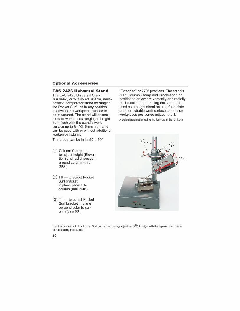
The EAS 2426 Universal Stand -
position comparator stand for staging the Pocket Surf unit in any position relative to the workpiece surface to be measured. The stand will accom-modate workpieces ranging in height
surface up to 8.4"/215mm high, and can be used with or without additional
The probe can be in its 90°,180°
“Extended” or 270° positions. The stand’s 360° Column Clamp and Bracket can be positioned anywhere vertically and radially on the column, permitting the stand to be used as a height stand on a surface plate or other suitable work surface to measure
A typical application using the Universal Stand. Note
1 Column Clamp — -
tion) and radial position around column (thru 360°)
Surf bracket in plane parallel to column (thru 360°)
Surf bracket in plane perpendicular to col-umn (thru 90°)
surface being measured.
21
(cont’d)1. Mount the Pocket Surf unit in the
bracket on the Stand using the captive screw in the base of the bracket. The screw mates with the tapped hole in the bottom of the Pocket Surf housing. Tighten the screw using a screwdriver or coin; do not over tighten.
2. Using the appropriate controls,
Pocket Surf bracket (and the bottom of the Pocket Surf housing) is paral-lel to the surface to be measured and the probe skid and stylus are barely in contact with surface. Use the Fine
Reference Line on the Probe Mounting Block parallel to the bottom of the Pocket Surf housing (as outlined in the Operation section).
and the probe is properly positioned on the workpiece surface, gently press and release the “Start” button on the Pocket Surf unit to make the measurement.
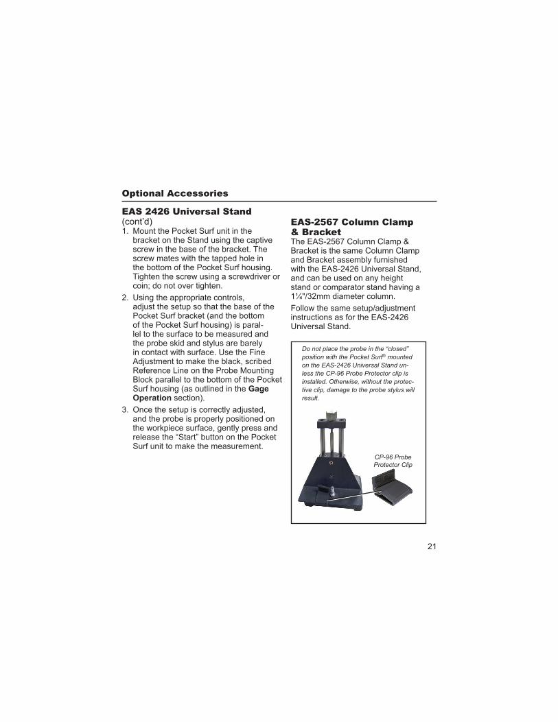
The EAS-2567 Column Clamp & Bracket is the same Column Clamp and Bracket assembly furnished with the EAS-2426 Universal Stand, and can be used on any height stand or comparator stand having a 1¼"/32mm diameter column.
instructions as for the EAS-2426 Universal Stand.
® mounted
-
-
result.
22
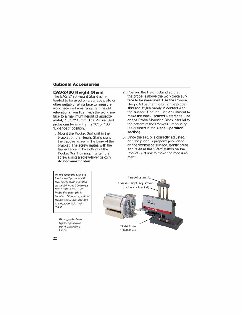
The EAS-2496 Height Stand is in-tended to be used on a surface plate or
workpiece surfaces ranging in height -
face to a maximum height of approxi-mately 4 3/8"/110mm. The Pocket Surf probe can be in either its 90° or 180° “Extended” position.
1. Mount the Pocket Surf unit in the bracket on the Height Stand using the captive screw in the base of the bracket. The screw mates with the tapped hole in the bottom of the Pocket Surf housing. Tighten the screw using a screwdriver or coin;
.
typical application
2. Position the Height Stand so that the probe is above the workpiece sur-face to be measured. Use the Coarse
skid and stylus barely in contact with
make the black, scribed Reference Line on the Probe Mounting Block parallel to the bottom of the Pocket Surf housing (as outlined in the section).
and the probe is properly positioned on the workpiece surface, gently press and release the “Start” button on the Pocket Surf unit to make the measure-ment.
Do not place the probe in
® mounted
result.
(on back of bracket)
CP-96 Probe
Protector Clip
23
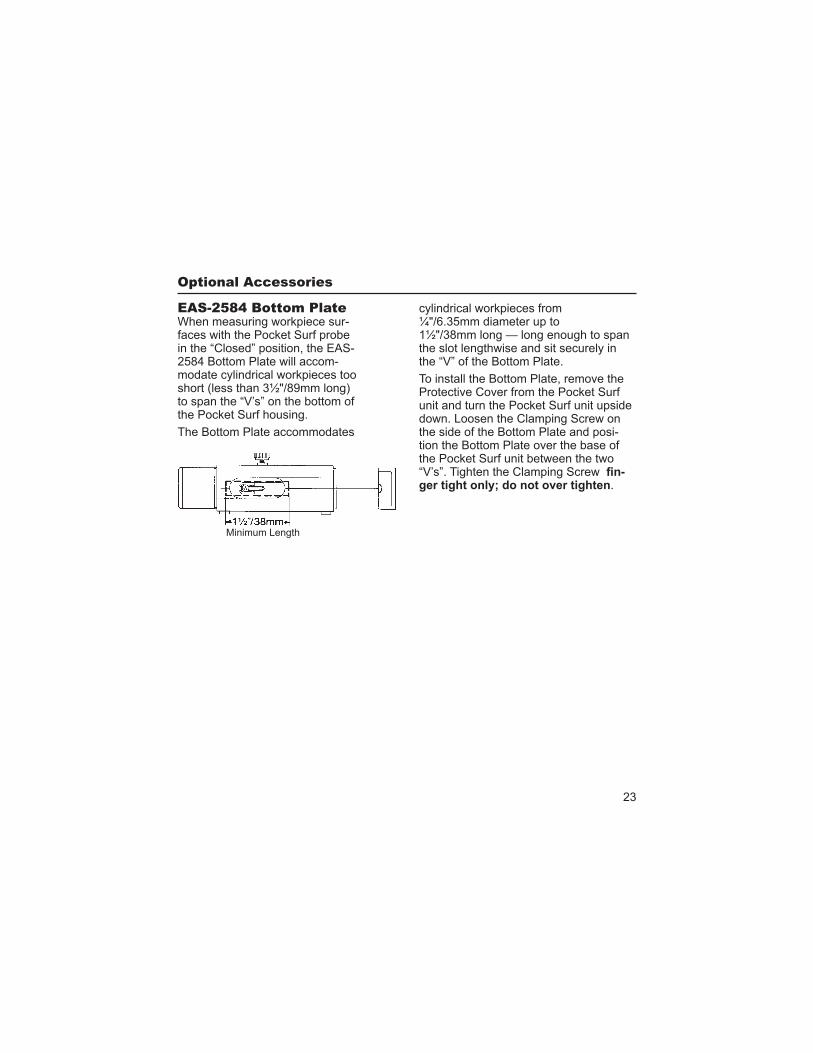
When measuring workpiece sur-faces with the Pocket Surf probe in the “Closed” position, the EAS-2584 Bottom Plate will accom-modate cylindrical workpieces too short (less than 3½"/89mm long) to span the “V’s” on the bottom of the Pocket Surf housing.
The Bottom Plate accommodates
cylindrical workpieces from ¼"/6.35mm diameter up to 1½"/38mm long — long enough to span the slot lengthwise and sit securely in the “V” of the Bottom Plate.
To install the Bottom Plate, remove the Protective Cover from the Pocket Surf unit and turn the Pocket Surf unit upside down. Loosen the Clamping Screw on the side of the Bottom Plate and posi-tion the Bottom Plate over the base of the Pocket Surf unit between the two “V’s”. Tighten the Clamping Screw -
.
Minimum Length
24
To protect the gage when not in use, always return the probe to its “Closed” position and replace the Protective Cover on the Pocket Surf unit. Also, when not in use, always keep the Pocket
carrying case.
To clean the Pocket Surf unit, use a soft, lint free cloth moistened with a mild, non abrasive, liquid or foam cleaning agent.
-
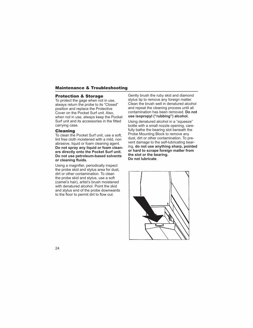
the probe skid and stylus area for dust, dirt or other contamination. To clean the probe skid and stylus, use a soft (camel’s hair), artist’s brush moistened with denatured alcohol. Point the skid and stylus end of the probe downwards
Gently brush the ruby skid and diamond stylus tip to remove any foreign matter. Clean the brush well in denatured alcohol and repeat the cleaning process until all contamination has been removed. Do not
Using denatured alcohol in a “squeeze” bottle with a small nozzle opening, care-fully bathe the bearing slot beneath the Probe Mounting Block to remove any dust, dirt or other contamination. To pre-vent damage to the self-lubricating bear-ing,
.
25
E1 — Motor did not start.
E2 — Motor failed to accelerate to proper operating speed.
E3 — Motor failed to maintain proper operating speed.
E4 — Excessive traverse length.
If error message “E1” or “E4” is dis-played on the digital readout, it usually indicates an internal electrical or me-chanical malfunction requiring repair; see the Repairs section on page 26.
If error message “E2” or “E3” is displayed on the digital readout, it usu-ally indicates that a malfunction has occurred in the probe traverse which prevented or interfered with normal movement. One or more of the follow-ing conditions may be the cause:
1. An obstruction or excessive pres-sure on the probe or the Probe Holding Block.
2. Dust, dirt or other contamination around the probe skid and stylus, and/or in and around the bearing and its slot beneath the Probe Hold-ing Block.
3. A weak battery (but not weak enough to cause the “low” battery signal to be displayed on the read-out).
(continued)
To remedy these conditions:
1. Make sure the workpiece is clean and dry, and the surface to be measured is free from gross defects.
2. Make sure the gage and workpiece -
face to be measured at approximately the same elevation as the base of the Pocket Surf unit and parallel to it, and the Reference Line on the Probe Mount-ing Block parallel to the bottom edge of the Pocket Surf housing (as outlined in the section on page 9).
26
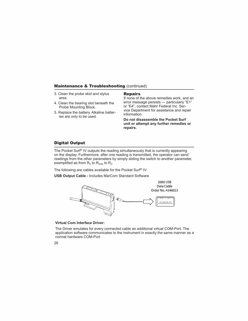
The Pocket Surf® IV outputs the reading simultaneously that is currently appearing on the display. Furthermore, after one reading is transmitted, the operator can send readings from the other parameters by simply sliding the switch to another parameter,
a to Rmax to Rz.
The following are cables available for the Pocket Surf® IV:
Includes MarCom Standard Software
(continued)
3. Clean the probe skid and stylusarea.
4. Clean the bearing slot beneath theProbe Mounting Block.
5. Replace the battery. Alkaline batter-ies are only to be used.
If none of the above remedies work, and an error message persists — particularly “E1” or “E4”, contact Mahr Federal Inc. Ser-vice Department for assistance and repair information.
repairs.
The Driver emulates for every connected cable an additional virtual COM-Port. The application software communicates to the instrument in exactly the same manner as a normal hardware COM-Port
27
*