Embed Size (px)
Citation preview
Position Estimation and Control of Compact BLDC Motors Based onAnalog Linear Hall Effect Sensors
Alex Simpkins† and Emanuel Todorov‡
Abstract— Bio-mimetic robotic systems, among many otherengineered systems, require motors which possess high torque,little or no torque ripple, compact size, and precise positioncontrol. It is frequently challenging to include a motor with adesign which fits all of these requirements. Several companieshave recently released compact pancake brushless DC motorswhich possess excellent characteristics. However, ripple-freeprecision control of brushless motors requires precision positionmeasurement. It can be difficult to mount encoders directlyto the shafts of these motors, and for precision positioncontrol, a sensorless configuration may be inappropriate. Wepropose a novel method of measuring rotor position usinganalog Hall effect sensors to measure the magnetic field ofthe rotor magnets to create an absolute position measurementof the electrical cycle, which can be used efficiently to createa computationally simple motor control scheme. These Halleffect sensors are mounted directly to the motor and are highlycompact, have high bandwidth, are extremely low cost, andhave high precision, providing position measurements withinsignificant increases to motor size.
I. INTRODUCTION
Recently brushless DC (BLDC) motors[14] have gainedtremendous popularity. They have been constructed in allshapes and sizes from very small - only a centimeter or less,to very large - motors requiring kiloWatts to run. BLDCmotors are found in computer peripherals, surgical devices,portable pumps, robotics[12], haptics[5], and electric cars toname a few examples. As a result, many embedded systemsmanufacturers are providing application notes, technical pa-pers, hardware to aid in development, and firmware designedto encourage engineers and scientists to use their productswith the many BLDC motor applications.
One strength of these new BLDC motors is that they havehigh torque and can be purchased in a very compact size(for example, the Maxon EC series and Portescap NuvoDiskseries). As a result they have been included in many roboticsand compact industrial designs such as in [8] and [13] ormost hard drives, optical drives, cooling fans, and more. Forsystems where the motor is to spin at a constant velocityand/or direction, there are many simple ’sensorless’ controlschemes[15] which can be used to drive the motor.
At high speeds torque ripple plays an insignificant roleas well, and so for the constant speed/sensorless applica-tions, there is less emphasis on unique position measure-ment and torque ripple compensation. But for applicationswhere precision position control is important, and the systemis highly compact - with minimal space surrounding themotor, it may be very difficult to mount standard sensors(encoders, potentiometers, etc). In addition, if one wereto use standard sensors, the sensor commutation patternmust be repeated several times (electrical revolutions) permechanical revolution. The number of repetitions varies permotor, and any position measurement must be mapped into
This work was supported by the US National Science Foundation†Department of Computer Science and Engineering, University of Wash-
ington, AC101 Paul G. Allen Center, Box 352350, 185 Stevens Way, Seattle,WA, 98195-2350, email: [email protected]
‡Department of Computer Science and Engineering, University of Wash-ington, AC101 Paul G. Allen Center, Box 352350, 185 Stevens Way, Seattle,WA, 98195-2350, email: [email protected]
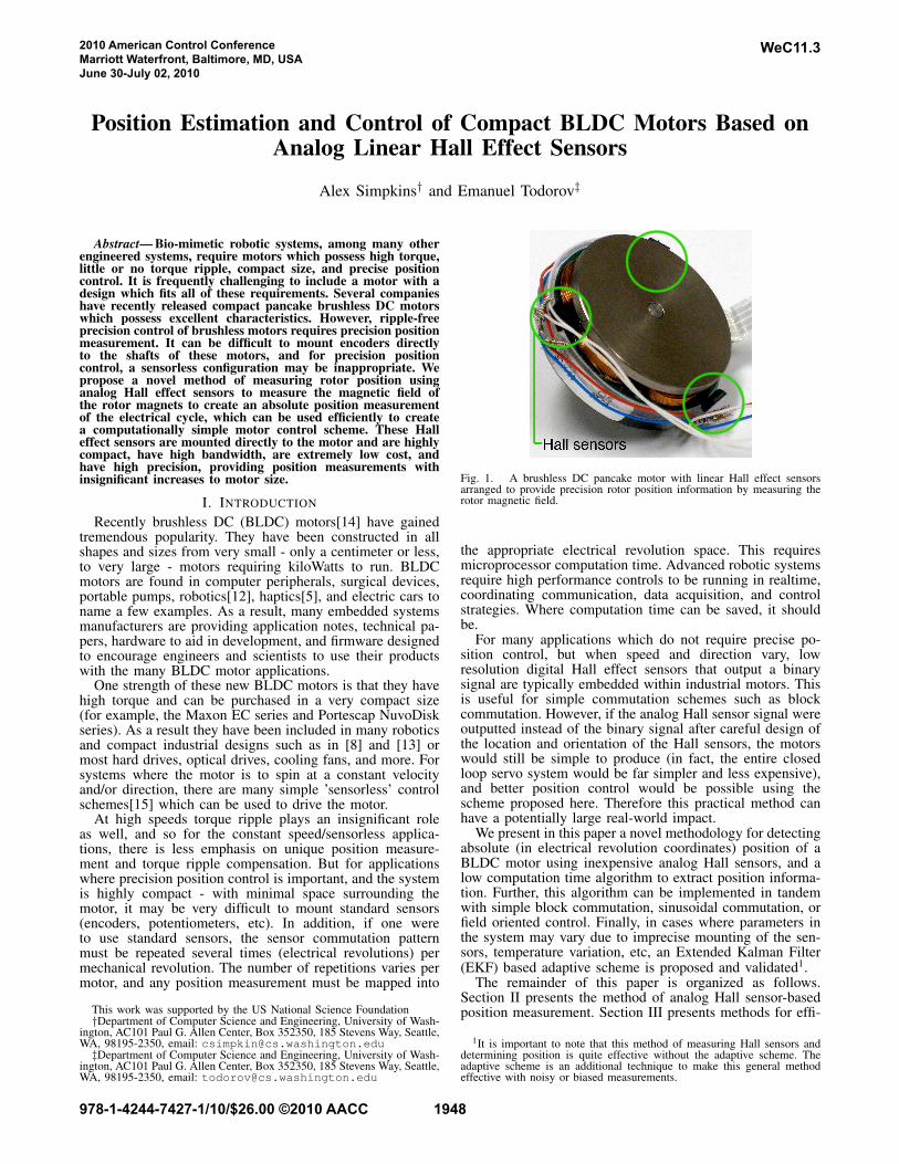
Fig. 1. A brushless DC pancake motor with linear Hall effect sensorsarranged to provide precision rotor position information by measuring therotor magnetic field.
the appropriate electrical revolution space. This requiresmicroprocessor computation time. Advanced robotic systemsrequire high performance controls to be running in realtime,coordinating communication, data acquisition, and controlstrategies. Where computation time can be saved, it shouldbe.
For many applications which do not require precise po-sition control, but when speed and direction vary, lowresolution digital Hall effect sensors that output a binarysignal are typically embedded within industrial motors. Thisis useful for simple commutation schemes such as blockcommutation. However, if the analog Hall sensor signal wereoutputted instead of the binary signal after careful design ofthe location and orientation of the Hall sensors, the motorswould still be simple to produce (in fact, the entire closedloop servo system would be far simpler and less expensive),and better position control would be possible using thescheme proposed here. Therefore this practical method canhave a potentially large real-world impact.
We present in this paper a novel methodology for detectingabsolute (in electrical revolution coordinates) position of aBLDC motor using inexpensive analog Hall sensors, and alow computation time algorithm to extract position informa-tion. Further, this algorithm can be implemented in tandemwith simple block commutation, sinusoidal commutation, orfield oriented control. Finally, in cases where parameters inthe system may vary due to imprecise mounting of the sen-sors, temperature variation, etc, an Extended Kalman Filter(EKF) based adaptive scheme is proposed and validated1.
The remainder of this paper is organized as follows.Section II presents the method of analog Hall sensor-basedposition measurement. Section III presents methods for effi-
1It is important to note that this method of measuring Hall sensors anddetermining position is quite effective without the adaptive scheme. Theadaptive scheme is an additional technique to make this general methodeffective with noisy or biased measurements.
2010 American Control ConferenceMarriott Waterfront, Baltimore, MD, USAJune 30-July 02, 2010
WeC11.3
978-1-4244-7427-1/10/$26.00 ©2010 AACC 1948
ciently combining the position estimation method with blockcommutation, with sinusoidal commutation, and with sinu-soidal commutation in tandem with an adaptive algorithmusing an EKF. Section IV presents results comparing theimplementations of the methods from Section III with themethods of Section II, then discusses the implications ofthese results. Finally, Section V concludes the paper withsome remarks and future works.
II. ANALOG HALL EFFECT SENSOR-BASED POSITION
MEASUREMENT
A. Review of the design of BLDC Motors
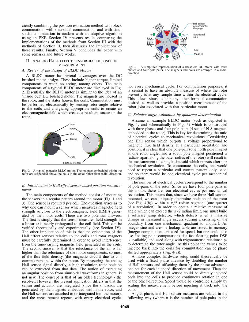
A BLDC motor has several advantages over the DCbrushed motor design. These include higher torque, limitedcomponents to wear, no arcing, among others. The maincomponents of a typical BLDC motor are displayed in Fig.2. Essentially the BLDC motor is similar to the idea of an’inside out’ DC brushed motor. The magnets are housed inthe rotor, and the stator houses the coils. Commutation mustbe performed electronically by sensing rotor angle relativeto the coils and energizing appropriate coils to create anelectromagnetic field which creates a resultant torque on therotor.
2OTOR
3TATOR
#OIL
%LECTRICALINTERFACE
3HAFT
"EARING
Fig. 2. A typical pancake BLDC motor. The magnets embedded within therotor are suspended above the coils in the axial rather than radial direction.
B. Introduction to Hall effect sensor-based position measure-ments
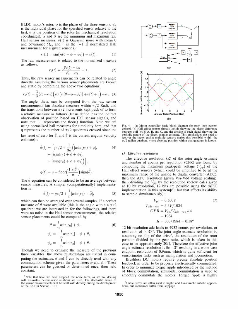
The main components of the method consist of mountingthe sensors in a regular pattern around the motor (Fig. 1 and3). One sensor is required per coil. The question arises as towhy one can mount a sensor which measures magnetic fieldstrength so close to the electromagnetic field (EMF) gener-ated by the motor coils. There are two potential answers.The first is simply that the sensor measures field strength ina linear axis nearly orthogonal to the coil field. This can beverified theoretically and experimentally (see Section IV).The other implication of this is that the orientation of theHall effect sensors relative to the coils and rotor magnetsmust be carefully determined in order to avoid interferencefrom the time-varying magnetic field generated in the coils.The second answer is that the reluctance of the air is farhigher than the reluctance of the motor components, so mostof the flux field density (the magnetic circuit) due to coilcurrents remains within the motor. By measuring the analogHall sensor signal directly, a high resolution rotor positioncan be extracted from that data. The notion of extractingan angular position from sinusoidal waveforms in general isnot new. The concept is that of an older technology - theresolver. However, the present application differs in that thesensor and actuator are integrated (since the sinusoids aregenerated by the magnets embedded within the rotor, andthe Hall sensors are attached to or integrated into the motor),and the measurement repeats with every electrical cycle,
NS Rotationalaxis
NS
N N
S
S
Coil
Magnet
A
A‘
C
C‘
B
B‘
Hall sensororiented into the page
Ha Hb
Hc
Fig. 3. A simplified representation of a brushless DC motor with threephases and four pole pairs. The magnets and coils are arranged in a radialdirection.
not every mechanical cycle. For commutation purposes, itis central to have an absolute measure of where the rotorpresently is at any sample time within the electrical cycle.This allows sinusoidal or any other form of commutationdesired, as well as provides a position measurement of therobot joint associated with that particular motor.
C. Relative angle estimation by quadrant determination
Assume an example BLDC motor (such as depicted inFig. 1, and schematically in Fig. 3) which is constructedwith three phases and four pole-pairs (4 sets of N-S magnetsembedded in the rotor). This is key for determining the ratioof electrical cycles to mechanical revolutions. Consideringone Hall sensor which outputs a voltage proportional tomagnetic flux field density at a particular orientation andposition, it is clear that one pole-pair (one north pole magnetat one rotor angle, and a south pole magnet positioned πradians apart along the outer radius of the rotor) will result inthe measurement of a single sinusoid which repeats after onemechanical revolution. To commutate the coils, one wouldneed to repeat a particular coil current pattern only once,and so there would be one electrical cycle per mechanicalrevolution.
The number of electrical cycles correspond to the numberof pole-pairs of the rotor. Since we have four pole-pairs inthis motor, there are four electrical cycles per mechanicalrevolution. This means that, since we have three Hall sensorsmounted, we can uniquely determine position of the rotor(see Fig. 4(b)) within a π/2 radian segment (one quarterof a revolution). In order to obtain a relative measure ofangle which can exceed the π/2 radian limit, one must builda software jump detector, which detects when a massivechange in measured angle occurs (during a crossing of theboundary from one mechanical quadrant to another). Aninteger sine and arcsine lookup table are stored in memory(integer computations are used for speed, but one could alsouse floating point computations if a fast floating point DSPis available) and used along with trigonometric relationshipsto determine the rotor angle. At this point the values to beinjected back into the coils for commutation can be phaseshifted appropriately (Fig. 4(a)).
A more complex hardware setup could theoretically beused with a fixed phase advance by doubling the numberof Hall sensors and offsetting them by the phase advance -one set for each intended direction of movement. Then themeasurement of the Hall sensor could be directly injectedback into the coils to produce continuous rotation in oneor the other direction. Speed would be controlled simply byscaling the measurement before injecting it back into thecoils.
Angle, phase, and Hall sensor measures are related in thefollowing way (where n is the number of pole-pairs in the
1949
BLDC motor’s rotor, φ is the phase of the three sensors, ψiis the individual phase for the specified sensor relative to thefirst, θ is the position of the rotor (in mechanical revolutioncoordinates), α and β are the minimum and maximum rawHall sensor measures, v(t) is Gaussian noise with mean 0and covariance Ωv , and r is the [−1, 1] normalized Hallmeasurement for a given sensor i):
ri(t) = sin(
n(θ − φ− ψi))
+ v(t). (1)
The raw measurement is related to the normalized measureas follows:
ri(t) = 2ri(t) − αiβi − αi
− 1. (2)
Thus, the raw sensor measurements can be related to angledirectly, assuming the various sensor placements are knownand static by combining the above two equations:
ri(t) =1
2(βi−αi)
(
sin(
n(θ−φ−ψi))
+v(t)+1)
+αi. (3)
The angle, theta, can be computed from the raw sensormeasurements (an absolute measure within π/2 Rad), andthe transitions between π/2 increments kept track of to form
a relative measure as follows (let us define θ as the indirectobservation of position based on Hall sensor signals, andnote that ⌊·⌋ represents the floor() function. Note we areusing normalized hall measures for simplicity here, and thatq represents the number of π/2 quadrants crossed since the
last reset of zero for θ, and˙θ is the current angular velocity
estimate)2:
θ(t) =[
qπ/2 +1
3n
(
[asin(r0) + φ], (4)
+ [asin(r1) + φ+ ψ1],
+ [asin(r2) + φ+ ψ2])]
,
q(t) = q + floor(1.8|
˙θ|
π
)
sign(˙θ).
The θ equation can be considered to be an average betweensensor measures. A simpler (computationally) implementa-tion is
θ(t) = qπ/2 +1
n[asin(r0) + φ], (5)
which can then be averaged over several samples. If a perfectmeasure of θ were available (this is the angle within a π/2quadrant we are interested in for the following), and therewere no noise in the Hall sensor measurements, the relativesensor placements could be computed by
θ =1
nasin[r0] + φ, (6)
ψ1 = −1
nasin[r1] − φ+ θ,
ψ2 = −1
nasin[r2] − φ+ θ.
Though we need to estimate the measure of the previousthree variables, the above relationships are useful in com-
puting the estimates. θ and θ can be directly used with anycommutation scheme given the parameters φ and ψi. Theseparameters can be guessed or determined once, then heldconstant.
2Note that here we have dropped the noise term, as we are dealingwith estimates, deterministic relations are used. The stochastic nature ofthe sensor measurements will be dealt with directly during the developmentof the EKF in Section III-C.
(a)
0 1 2 3 4 5 6−2
−1.5
−1
−0.5
0
0.5
1
1.5
2
Angular Rotor Position (Rad)No
rmali
zed
Hall
Sen
so
r M
easu
rem
en
ts (
V)
(b)
Fig. 4. (a) Motor controller basic block diagram for open loop currentcontrol. (b) Hall effect sensor signals (solid) showing the phase differencebetween coil (π/3) A, B, and C, and the arcsine of each signal showing theperiodic nature of the direct angular estimate. This emphasizes the need torecover the sector (using multiple sensors makes this possible) within theπ/2 radian quadrant where absolute position within that quadrant is known.
D. Effective resolution
The effective resolution (R) of the rotor angle estimateand number of counts per revolution (CPR) are found bycomputing the maximum peak-peak voltage (Vpp) of theHall effect sensors (which could be amplified to be at themaximum range of the analog to digital converter (ADC),then the ADC resolution (given Vss-Vdd voltage scaling),then dividing the Vpp by the resolution (below calcs givenat 10 bit resolution, 12 bits are possible using the dsPICimplementation in this system[6], but that affects its abilityto sample simultaneously):
Vpp = 0.400V (7)
Vadc−res = 3.3V/1024
CPR = Vpp/Vadc−res ∗ 4
= 1984
R = 360/1984 = 0.18o
12 bit resolution adc leads to 4932 counts per revolution, orresolution of 0.073o. The joint angle estimate resolution is,assuming no slip of the drive3, the resolution of the rotorposition divided by the gear ratio, which is taken in thiscase to be approximately 20:1. Therefore the effective jointangle estimate resolution is 9e−3o resulting in a worst caseendpoint resolution of 0.9mm, which is quite sufficient forsensorimotor tasks such as manipulation and locomotion.
Brushless DC motors require precise absolute positionfeedback in order to be properly electronically commutated.In order to minimize torque ripple introduced by the methodof block commutation, sinusoidal commutation is used tosmoothly commutate the motors. Torque ripple is highly
3Cable drives are often used in haptic and bio-mimetic robotic applica-tions, but sometimes suffer from slippage.
1950
undesirable in a system to be used for manipulation andlocomotion.
III. COMBINING HALL EFFECT SENSOR POSITION
ESTIMATES WITH BLOCK, SINUSOIDAL, AND ADAPTIVE
SINUSOIDAL COMMUTATION METHODS.
A. Block commutation
The simplest method of commutating a BLDC motoris ’trapezoidal’ or ’block’ commutation. This in generalconsists of a few steps, beginning with measuring rotorposition via (high or low resolution) Hall sensors, opticalor magnetic encoders, or back-EMF (bEMF) generated byeach coil. When low resolution Hall sensors are used incommon applications, a rotor-position-dependent code (Fig.5) is present in the Hall sensor data (typically Hall sensoroutputs are filtered to be a binary signal - here referred toas digital Hall sensor circuits or DHS). In stages, a pair ofcoils are connected in such a way as to allow current toflow between the two coils, forming a field which draws therotor to rotate to align opposing fields. As the rotor rotates,the Hall sensor ’code’ changes, and the current is alteredto flow through appropriate pairs of coils to continuouslydraw the rotor toward the moving field. It is important tonote that this switching of the field flow leads to a torqueripple effect which is dependent on several motor parameters(most notable are rotor position and speed) in terms of peak-to-peak wave amplitude. This method of commutating BLDC
B+
C-
C+
A-
1
0
1
0
1
0
Tavg
Hall
Sensor
Output
A
B
C
bEMF
Motor
Torque
A+
B-+
0
-
+
0
-
+
0
-
1 Mechanical Revolution
0
0 180 360 540 720
1 Electrical cycle 1 Electrical cycle
Fig. 5. This denotes block commutation over one mechanical revolutionfor a typical three-phase BLDC motor with trapezoidal bEMF (adaptedfrom AN885 technical note document from microchip.com). The torqueripple due to commutation is evident, and is undesirable for fine bio-mimeticcontrol experiments.
motors is therefore more desirable in situations in whichmotor speed will tend to be higher and more constant becausethe torque ripple is velocity dependent due to the inertiaand the time constant of the motor. In the case dealing withlocomotion and object manipulation using highly sensitiverobotic systems, RPMs tend to be low or nearly zero,directions change frequently, and the motor occasionally willbe stalled. A commutation method which creates a smoothtransition between stator pole locations must be employed.
Sinusoidal commutation is appropriate for low speeds, andin many bio-mimetic[7][11] robotic applications (manipu-lation and locomotion), speeds are relatively low, thoughtorques may be high.
B. Method of sinusoidal commutation
The maximum torque upon the rotor can be exerted whenone of the poles is positioned directly between a pair of coils
which are creating a field of opposing magnetic orientation.Considering the coordinate system of the rotor, the force dueto the field generated in the coil acting upon the rotor can bedecomposed into a tangential component and an orthogonalcomponent which creates a torque balanced by the motorbearings as opposed to causing a rotation.
If the fields of the coil and permanent magnets are aligned,the rotor will be stationary. If they are misaligned slightly, atorque will act to rotate the rotor until they are aligned. If themisalignment is perpetuated by rotating the coil-based fieldahead of the rotor’s rotation, a continuous, cog-free rotationof the rotor occurs. The torque generated will be determinedby the amplitude of the sinusoids (which, in a digital system,can be realized via PWM), as well as the degree of phaseshift of the active fields.
The fields are a sinusoidal function of rotor angularposition, with each coil phase-shifted (since each coil in athree-phase motor is physically phase shifted by 60 or 120degrees) and then phase shifted relative to rotor position.This rotor position phase shift can be constant or dynamic -a function of rotor speed. The relations are given (where A,B, and C are the coil PWM commands for coil A, B, andC respectively, θ is the rotor angle estimate, φ is the ’shift’of all sensors relative to a midpoint between coils, ψi is theplacement of the second and third sensors relative to the first,M is the command, and ρ is the phase advance desired bythe engineer tuning the system) by
A = Msin(
θ − φ+ ρ)
, (8)
B = Msin(
θ − φ+ ρ− ψ1
)
,
C = Mmax −A−B.
Note that, since total current entering and leaving the systemmust be zero, C is a driven quantity.
To rotate in the opposing direction, one must merelycompute the complement of the first two equations (the thirdis still driven):
A = Mmax −Msin(
θ − φ+ ρ)
, (9)
B = Mmax −Msin(
θ − φ+ ρ− ψ1
)
,
C = Mmax −A−B.
C. Parameter estimation via Extended Kalman Filter
Several parameters associated with controlling the motorfor maximum torque generation include individual Hallsensor position, phase shift, maximum and minimum foreach sensor.Since the main parameters have simple state-dependent nonlinear dynamics, they can be estimated byan EKF with ’fast’ noise processes driving them to a zeroestimation error. It is emphasized again here that the EKFis not necessarily needed if one is most concerned about asimple application, but it is presented for added precision andto improve performance. In many cases, simply computingan angle based on what was discussed earlier and directlyusing that for commutation is effective. The EKF makes thegeneral methodology applicable in more cases than otherwisepossible. We need to estimate φi, αi, and βi for all i,knowing only the ideal and initial conditions. We also wantto use these estimates to estimate θ as well. α0
i and β0
iare computed after power-up during an initialization routine.Then all the parameters must be gradually adjusted overtime (e.g. the Hall sensors may shift with temperature whichaffects magnitude and phase). The future estimates are propa-gated by a discrete EKF[3][1][10] with continuous dynamicsand observation model. Noise processes are assumed to beGaussian, with mean 0 and covariance Ω.
1951
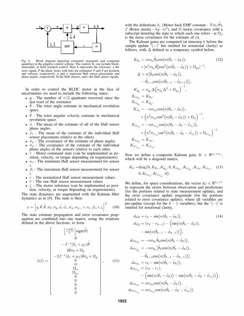
Fig. 6. Block diagram depicting estimated, measured, and computedquantities in the adaptive control scheme. The control, K, can include block,sinusoidal, or field oriented control. Here h represents the reference, e the
error signal, P the plant, items with hats are estimated, θ and θ are positionand velocity, respectively, φ and ψ represent Hall sensor placements andphase angles, respectively, H the Hall sensors, and r the Hall sensor signals.
In order to control the BLDC motor in the face ofuncertainties we need to include the following states:
• q - The number of π/2 quadrants traversed since thelast reset of the estimator.
• θ - The rotor angle estimate in mechanical revolutionspace.
•˙θ - The rotor angular velocity estimate in mechanicalrevolution space.
• φ - The mean of the estimate of all of the Hall sensorphase angles.
• ψi - The mean of the estimate of the individual Hallsensor placements relative to the others.
• σφ - The covariance of the estimate of phase angles.• σψ - The covariance of the estimate of the individual
phase angles of the sensors relative to each other.• τ - Motor command state (can be implemented as po-
sition, velocity, or torque depending on requirements).• αi - The minimum Hall sensor measurement for sensori.
• βi - The maximum Hall sensor measurement for sensori.
• r - The normalized Hall sensor measurement values.• r - The raw Hall sensor measurement values• ζ - The motor reference (can be implemented as posi-
tion, velocity, or torque depending on requirements).
The state dynamics are augmented with the Kalman filterdynamics as in [9]. The state is then:
x =[
q, θ,˙θ, σθ, σθ, φ, ψi, σφ, σψi , τ, αi, βi, r, ζ
]T
(10)
The state estimate propagation and error covariance prop-agation are combined into one matrix, using the relationsdefined in the above Sections, to form
˙x(t) =
⌊
1.8|˙θ|
π
⌋
sign(˙θ)
˙θ
−J−1(ke + µf )˙θ
2˙θσθ + Ωθ
−2J−1(ke + µf )˙θσθ + Ωθ
00
ΩφΩψi00000
, (11)
with the definitions ke (Motor back EMF constant - Nm/˙θ),
J (Rotor inertia - kg ·m2), and Ω (noise covariance with asubscript denoting the state to which each one refers - ie Ωφis the noise covariance for the estimate of φ).
The Kalman gains are computed (at timestep k before thesample update ′(−)′ but omitted for notational clarity) asfollows, with ∆ defined as a temporary symbol below,
Kθk = nσθk˙θkcos
(
n(θk − φk))
, (12)
∗ [n2σθk˙θ2kcos2
(
n(θk − φk))
+ Ωyθ ]−1,
∆ = n[ ˙θkcos
(
n(θk − φk))
,
−˙θk−1cos
(
n(θk−1 − φk−1))]
,
Kθk= σθk∆
(
σθk∆2 + Ωy
θ
)−1
,
Kσθk= Kθk ,
Kσθk
= Kθk,
Kφk = −nσφkcos(
n(θk − φk))
,
∗(
n2σφkcos2(
n(θk − φk))
+ Ωφ
)−1
,
Kψik= −nσψik cos
(
n(θk − φk − ψik))
,
∗(
n2σψik cos2(
n(θk − φk − ψik))
+ Ωψik
)−1
Kσφk= Kφk ,
Kσφik= Kψik
.
Now we define a composite Kalman gain, K ∈ ℜnx×nx ,which will be a diagonal matrix,
Kk =diag0,Kθk ,Kθk, 0,Kσθk
,Kσθk,Kφk ,Kψik
, (13)
0,Kσφk,Kσφik
, 0.
We define, for space considerations, the vector dω ∈ ℜnx×1
to represent the errors between observation and predictions(for the portions related to state measurement update), andthe error covariance update magnitude (for the portionsrelated to error covariance update), where all variables arepre-update (except for the k − 1 variables), but the ′(−)′ isomitted for notational clarity,
dωθ = r0 − sin(
n(θk − φk))
, (14)
dωθ = (rk − rk−1) −(
sin(
n(θk − φk))
,
− sin(
n(θk−1 − φk−1))
)
,
dωσθk = −nσθk˙θkcos
(
n(θk − φk))
,
dωσθk
= −nσθk[ ˙θkcos
(
n(θk − φk))
,
−˙θk−1cos
(
n(θk−1 − φk−1))]
,
dωφk = r0 − sin(
n(θk − φk))
,
dωψik = (r0 − r1),
−(
sin(
n(θk − φk))
− sin(
n(θk − φk − ψik))
)
,
dωσφk = nσφkcos(
n(θk − φk))
,
dωσψik= nσψik cos
(
n(θk − φk − ψik))
.
1952
The state estimate update and error covariance update arecombined into one set of calculations in the following way,
0
θk(+)˙θk(+)σθk(+)σθk(+)
φk(+)
ψik(+)σφk(+)σψik (+)
0
=
0
θk(−)˙θk(−)σθk(−)σθk(−)
φk(−)
ψik(−)σφk(−)σψik (−)
0
+Kk
0dωθkdωθkdωσθkdωσ
θk
dωφkdωψikdωσφkdωσψik
0
. (15)
The variable phase φ can be omitted from this part ofthe estimation and held constant, tuned during a startupprocedure, or allowed to drift only slowly, as it is mainlya torque maximizing variable. Thus if all the other pa-rameters converge to the correct value, and φ is slightlynon-optimized, the motor will function. It merely will notfunction at peak torque capability. If the value moves outsideof about π/2 Radians, the torque generated in the BLDCmotor will swap sign, and excessive current flow and coiltemperature increases will occur.
Now that the estimation scheme has been developed, andsince it is separate from the commutation scheme employed,the estimates coming out of the EKF can be used with anycommutation scheme. In Fig. 6, the commutation scheme islumped within the control K.
D. Other issues to consider
After all this work developing a commutation method forprecision control and minimization of ripple, it would bedisconcerting to implement the system and have other factorscause ripple and imprecision. We will now consider twoother issues - a simple way to deal with friction and othernonlinearities, and how to choose PWM cycle frequency.
1) Reducing ripple due to friction and nonlinearities in theelectronics by local feedback: Since friction and electronicssuch as the intrinsic freewheeling diodes contribute nonlineareffects to the motor dynamics, a local proportional feedbackcontroller is implemented to account for these effects - takingin a particular current command, and outputting a PWMcommand. The actual coil current is measured with the useof high precision current sensing resistors. This measure isused as a feedback signal to drive the system to desired levelsand prevent excess current flow (Fig. 7).
Fig. 7. Local feedback control helps cancel nonlinearities due to friction,and nonlinear electrical characteristics in the motor.
The controller can be a P, PI, PD, or PID controller. Evenif a proportional control is used, performance can improvesignificantly. The gain is set using a standard classical controlmethod - find the gain at which the system becomes unstableand then reduce the gain by an arbitrary factor such asone half. A good treatment of related nonlinear phenomenais given in[2], and an example of improvement with aninteresting application is given in [4].
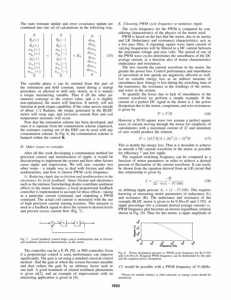
E. Choosing PWM cycle frequency to minimize ripple
The cycle frequency for the PWM is computed by con-sidering characteristics of the physics of the motor used.
PWM is based on the fact that the motor, due to its inertiaand LR (Inductance and resistance) characteristics, acts asa low pass filter. A repeating square wave input current ofvarying frequencies will be filtered to a DC current betweenthe maximum voltage and zero volts. The period of one ofthe PWM wave cycles determines the smoothness of the DCaverage current, as a function also of motor characteristics(inductance and resistance).
The less smooth the current waveform in the motor, thegreater the power loss. Control performance and smoothnessof movement at low speeds are negatively affected as well.Let us consider energy loss as an indirect measure ofsmoothness here. Energy is lost during the switching time ofthe transistors, the resistance in the windings of the motor,and wires in the system.
To quantify the losses due to lack of smoothness of thecurrent waveform we perform a simple example. If thecurrent of a perfect DC signal in the motor is I, the powerdissipation due to the motor, component, and wire resistancesis given by
P = I2R (16)
However a 50:50 square wave (we assume a perfect squarewave of current moving through the motor for simplicity ofcalculations) with a maximum current of 2I and minimumof zero would produce the relation
P = (2I)2R/2 + (0)2/2 = 2I2R (17)
This is double the energy loss. Thus it is desirable to achieveas smooth a DC current waveform in the motor as possiblefor efficiency 4 and low ripple.
The required switching frequency can be computed as afunction of motor parameters in order to achieve a desiredpercent of fluctuation of the current waveform. It can easilybe shown from the equation derived from an LR circuit thatthis relationship is given by
f =−R
2L · ln(1 − P/100)(18)
or, defining ripple percent Ar = (1− P/100). This requiresknowing or measuring motor parameters of inductance (L)and resistance (R). The inductance and resistance of theexample BLDC motor is given to be 0.36mH and 3.75Ω. Aripple percentage (for a constant desired average current) vs.PWM frequency plot becomes an inverse logarithmic relationshown in Fig. (8). Thus for this motor, a ripple amplitude of
101
102
103
104
105
106
10−1
100
101
102
Rip
ple
(%
)
Frequency (Hz)
Fig. 8. Power dissipation percent vs. PWM cycle frequency for R=3.75Ωand L=0.36mH . Required PWM frequency can be determined by this plotand the required power dissipation.
1% would be possible with a PWM frequency of 51.8kHz.
4Power for mobile robotics is often onboard, so energy waste should beminimized
1953
Since the power amplification circuitry employed has anabsolute maximum PWM frequency of 50kHz, the minimumripple amplitude possible at this rate is 3.5%, which isstill acceptable. It should be noted that increasing PWMfrequency reduces effective resolution of the PWM dutycycle. The relation [6] is given by (with γ defined asresolution)
γ =log(2TPWM/TCY )
log(2). (19)
Here ’resolution’ is in bits. Thus the effective PWM res-olution at a frequency of 10kHz is roughly 4000, while at40kHz reduces to 1000.The PWM frequency can be adjustedby altering one or both parameters of the motor included inthis equation - namely the resistance and inductance. Weachieve satisfactory performance with this PWM frequency.
IV. RESULTS
A. Hall sensor-based measurements
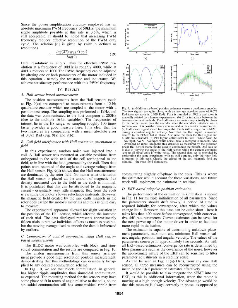
The position measurements from the Hall sensors (suchas Fig. 9(c)) are compared to measurements from a 12-bitquadrature encoder which are coupled to the motor with aposition test setup. The sampling was performed at 1kHz, andthe data was communicated to the host computer at 200Hz(due to the multiple 16-bit variables). The frequencies ofinterest lie in the Hz range, so sampling roughly 100 timesfaster provides a good measure here. It is clear that thetwo measures are comparable, with a mean absolute errorof 0.073 Rad (Fig. 9(a) and 9(b)).
B. Coil field interference with Hall sensor vs. orientation tofield
In this experiment, random noise was injected into acoil. A Hall sensor was mounted at variable positions fromorthogonal to the wide axis of the coil (orthogonal to thefield) to in line with the field generated by the coil. Then datapoints were recorded of the angle and average voltage fromthe Hall sensor. Fig. 9(d) shows that the Hall measurementsare dominated by the rotor field. No matter what orientationthe Hall sensor is placed at, the amount of magnetic fluxdensity measured due to the field in the coils is minimal.It is postulated that this can be attributed to the magneticcircuit - essentially very little magnetic flux from the coilsis escaping the motor’s lower reluctance materials. However,the magnetic field created by the rare earth magnets in therotor does escape the motor’s materials and thus is quite easyto measure.
The experimental apparatus allowed for slight variation inthe position of the Hall sensor, which affected the outcomeof each trial. The data displayed represents approximatelyfifteen trials to remove individual effects as much as possible,but the moving average used to smooth the data is influencedby outliers.
C. Comparison of control approaches using Hall sensor-based measurements
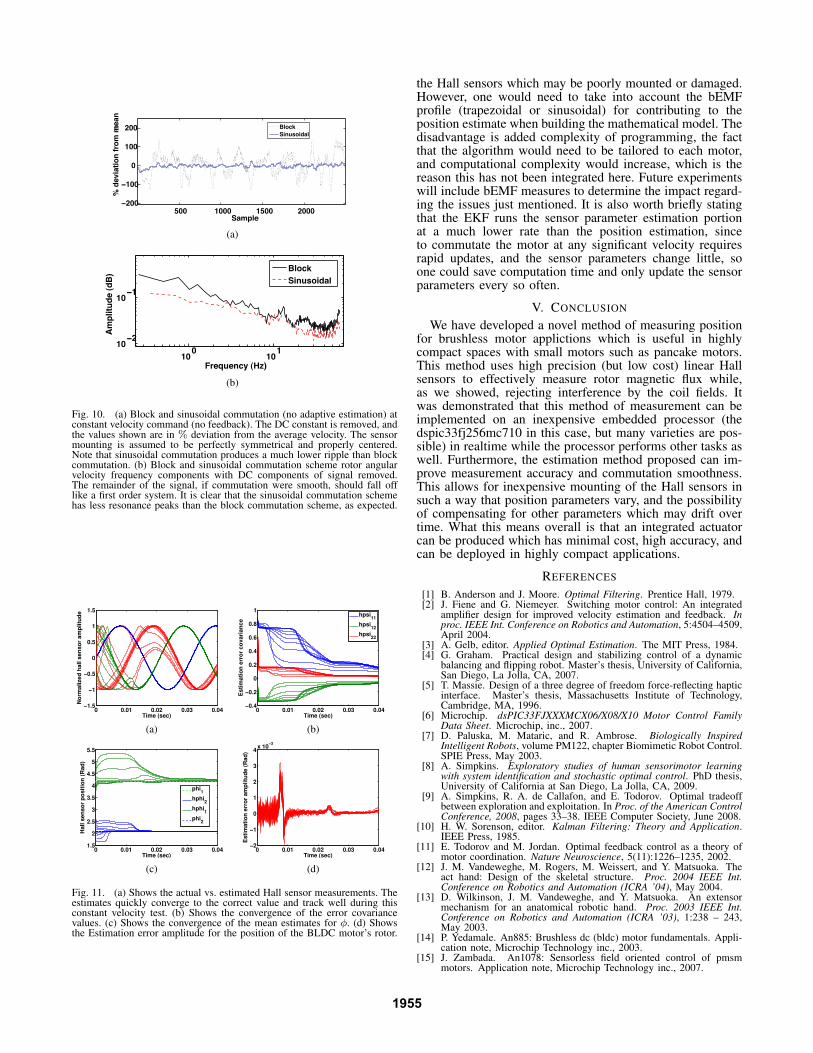
The BLDC motor was controlled with block, and sinu-soidal commutation and the results are compared in Fig. 10.
The analog measurements from this sensor arrange-ment provide a good high resolution position measurement,demonstrating that this methodology can essentially be ap-plied to any desired commutation scheme.
In Fig. 10, we see that block commutation, in general,has higher ripple amplitudes than sinusoidal commutation,as expected. The mounting method for the sensors may havesome phase shift in terms of angle relative to the coils, so thesinusoidal commutation still has some residual ripple from
5 10 15 20
10
12
14
16
18
20
22
Time (sec)
An
gu
lar
po
sit
ion
(ra
d)
Encoder
Hall−based
(a)
0 5 10 15−0.2
−0.15
−0.1
−0.05
0
0.05
0.1
0.15
Time (sec)
Err
or
(Rad
)
(b)
−0.02 −0.01 0 0.01 0.02−0.2
−0.15
−0.1
−0.05
0
0.05
0.1
0.15
0.2
Time (Sec)
Am
pli
tud
e (
V)
Hall
bEMF
(c)
−0.5 0 0.5
1300
1320
1340
1360
1380
Angle (Rad)
Mag
neti
c f
lux d
en
sit
y (
Gau
ss)
WN
NI
AWN
ANI
(d)
Fig. 9. (a) Hall sensor-based position estimates versus a quadrature encoder.The two signals are quite close, with an average absolute error of 0.073Rad (average error is 0.029 Rad). Data is sampled at 500Hz and rotor ismanually rotated by a human experimenter. (b) Error in radians between thetwo measurement methods. The Hall sensor estimates may actually be closerto the correct value than the encoder since the encoder’s interface was asoftware one. It is possible counts were missed in the encoder measurements.(c) Hall sensor signal scaled to comparable levels with a single coil’s bEMFduring a constant angular velocity. Note that the Hall signal is invertedrelative to the bEMF, but in phase. Also note that both the Hall signal andbEMF are sinusoidal. (d) Plot legend entries refer to: WN - White noise, NI- No input, AWN - Averaged white noise (data is averaged to smooth), ANI- Averaged no input. Magnetic flux densities as measured by the precisionlinear Hall sensor (same model used to commutate the motor). One data setis due to varying the angle of the Hall sensor while the current commandsent to all three coils is white noise. The second data set is provided byperforming the same experiment with no coil currents, only the rotor fieldis present in this case. Clearly the effects of the coil magnetic field areminimal - the rotor field dominates.
commutating slightly off-phase in the coils. This is wherethe estimator would account for these variations, and futurework will implement the estimator in realtime.
D. EKF-based adaptive position estimation
The performance of the estimation in simulation is shownin Fig. 11 for multiple initialization of all parameters. Sincethe parameters should drift slowly, a period of time isrequired initially for convergence, after which the valueschange little. However, this time can be quite short - here ittakes less than 400 msec before convergence, with conserva-tive drift rate parameters. Current estimates can be saved forthe next power-up of the motor driver in order to facilitatemore rapid initialization.
The estimator is capable of determining unknown place-ment parameters, maximum and minimum Hall sensor val-ues, angular position, and angular velocity. The values of theparameters converge in approximately two seconds. As withall EKF-based estimators, convergence rate is determined byfilter parameters such as the covariance of the noise, howeverthe approximate nature of the EKF can be sensitive to filterparameter adjustments in a stability sense.
As can be seen in Fig. 11(a)-11(d), from any one Hallsensor, all three measures can be reconstructed using themean of the EKF parameter estimates effectively.
It would be possible to also integrate the bEMF into theEKF, as this is additional information, when the motor ismoving at a high enough velocity. The advantage would bethat this measure is always correctly in phase, as opposed to
1954
500 1000 1500 2000−200
−100
0
100
200
Sample
% d
evia
tio
n f
rom
mean
ω
Block
Sinusoidal
(a)
100
101
10−2
10−1
Frequency (Hz)
Am
pli
tud
e (
dB
)
Block
Sinusoidal
(b)
Fig. 10. (a) Block and sinusoidal commutation (no adaptive estimation) atconstant velocity command (no feedback). The DC constant is removed, andthe values shown are in % deviation from the average velocity. The sensormounting is assumed to be perfectly symmetrical and properly centered.Note that sinusoidal commutation produces a much lower ripple than blockcommutation. (b) Block and sinusoidal commutation scheme rotor angularvelocity frequency components with DC components of signal removed.The remainder of the signal, if commutation were smooth, should fall offlike a first order system. It is clear that the sinusoidal commutation schemehas less resonance peaks than the block commutation scheme, as expected.
0 0.01 0.02 0.03 0.04−1.5
−1
−0.5
0
0.5
1
1.5
Time (sec)
No
rmalized
hall s
en
so
r am
plitu
de
(a)
0 0.01 0.02 0.03 0.04−0.4
−0.2
0
0.2
0.4
0.6
0.8
1
Time (sec)
Esti
mati
on
err
or
co
vari
an
ce
hpsi
11
hpsi12
hpsi22
(b)
0 0.01 0.02 0.03 0.041.5
2
2.5
3
3.5
4
4.5
5
5.5
Time (sec)
Hall s
en
so
r p
osit
ion
(R
ad
)
phi1
hphi2
hphi1
phi2
(c)
0 0.01 0.02 0.03 0.04−2
−1
0
1
2
3
4x 10
−3
Time (sec)
Esti
mati
on
err
or
am
plitu
de (
Rad
)
(d)
Fig. 11. (a) Shows the actual vs. estimated Hall sensor measurements. Theestimates quickly converge to the correct value and track well during thisconstant velocity test. (b) Shows the convergence of the error covariancevalues. (c) Shows the convergence of the mean estimates for φ. (d) Showsthe Estimation error amplitude for the position of the BLDC motor’s rotor.
the Hall sensors which may be poorly mounted or damaged.However, one would need to take into account the bEMFprofile (trapezoidal or sinusoidal) for contributing to theposition estimate when building the mathematical model. Thedisadvantage is added complexity of programming, the factthat the algorithm would need to be tailored to each motor,and computational complexity would increase, which is thereason this has not been integrated here. Future experimentswill include bEMF measures to determine the impact regard-ing the issues just mentioned. It is also worth briefly statingthat the EKF runs the sensor parameter estimation portionat a much lower rate than the position estimation, sinceto commutate the motor at any significant velocity requiresrapid updates, and the sensor parameters change little, soone could save computation time and only update the sensorparameters every so often.
V. CONCLUSION
We have developed a novel method of measuring positionfor brushless motor applictions which is useful in highlycompact spaces with small motors such as pancake motors.This method uses high precision (but low cost) linear Hallsensors to effectively measure rotor magnetic flux while,as we showed, rejecting interference by the coil fields. Itwas demonstrated that this method of measurement can beimplemented on an inexpensive embedded processor (thedspic33fj256mc710 in this case, but many varieties are pos-sible) in realtime while the processor performs other tasks aswell. Furthermore, the estimation method proposed can im-prove measurement accuracy and commutation smoothness.This allows for inexpensive mounting of the Hall sensors insuch a way that position parameters vary, and the possibilityof compensating for other parameters which may drift overtime. What this means overall is that an integrated actuatorcan be produced which has minimal cost, high accuracy, andcan be deployed in highly compact applications.
REFERENCES
[1] B. Anderson and J. Moore. Optimal Filtering. Prentice Hall, 1979.[2] J. Fiene and G. Niemeyer. Switching motor control: An integrated
amplifier design for improved velocity estimation and feedback. Inproc. IEEE Int. Conference on Robotics and Automation, 5:4504–4509,April 2004.
[3] A. Gelb, editor. Applied Optimal Estimation. The MIT Press, 1984.[4] G. Graham. Practical design and stabilizing control of a dynamic
balancing and flipping robot. Master’s thesis, University of California,San Diego, La Jolla, CA, 2007.
[5] T. Massie. Design of a three degree of freedom force-reflecting hapticinterface. Master’s thesis, Massachusetts Institute of Technology,Cambridge, MA, 1996.
[6] Microchip. dsPIC33FJXXXMCX06/X08/X10 Motor Control FamilyData Sheet. Microchip, inc., 2007.
[7] D. Paluska, M. Mataric, and R. Ambrose. Biologically InspiredIntelligent Robots, volume PM122, chapter Biomimetic Robot Control.SPIE Press, May 2003.
[8] A. Simpkins. Exploratory studies of human sensorimotor learningwith system identification and stochastic optimal control. PhD thesis,University of California at San Diego, La Jolla, CA, 2009.
[9] A. Simpkins, R. A. de Callafon, and E. Todorov. Optimal tradeoffbetween exploration and exploitation. In Proc. of the American ControlConference, 2008, pages 33–38. IEEE Computer Society, June 2008.
[10] H. W. Sorenson, editor. Kalman Filtering: Theory and Application.IEEE Press, 1985.
[11] E. Todorov and M. Jordan. Optimal feedback control as a theory ofmotor coordination. Nature Neuroscience, 5(11):1226–1235, 2002.
[12] J. M. Vandeweghe, M. Rogers, M. Weissert, and Y. Matsuoka. Theact hand: Design of the skeletal structure. Proc. 2004 IEEE Int.Conference on Robotics and Automation (ICRA ’04), May 2004.
[13] D. Wilkinson, J. M. Vandeweghe, and Y. Matsuoka. An extensormechanism for an anatomical robotic hand. Proc. 2003 IEEE Int.Conference on Robotics and Automation (ICRA ’03), 1:238 – 243,May 2003.
[14] P. Yedamale. An885: Brushless dc (bldc) motor fundamentals. Appli-cation note, Microchip Technology inc., 2003.
[15] J. Zambada. An1078: Sensorless field oriented control of pmsmmotors. Application note, Microchip Technology inc., 2007.
1955