Embed Size (px)
Citation preview

60
Position SensorsFor use in hazardous locations

Benefit from comprehensive
sensor expertise from a single
source. Achieve solutions suited
to your requirements.
Additional information can be found in our catalogs
"Object Detection" and "Linear Position Sensing and Measurement",
or on the internet at: www.balluff.com
With over 50 years of sensor experience, Balluff is a leading global
sensor specialist with its own line of connectivity products for every
area of factory automation. Balluff is based in Germany and has a
tight international network of 54 representatives and subsidiaries.
Balluff stands for comprehensive systems from a single source,
continuous innovation, state-of-the-art technology, highest
quality, and greatest reliability. That's not all: Balluff also stands
for exceptional customer orientation, customized solutions, fast
worldwide service, and outstanding application assistance.
High-quality, innovative products tested in our own accredited
laboratory and a quality management system certified according
to DIN ISO 9001 (EN 2008) form a secure foundation for optimized
added value for our customers.
Whether electronic and mechanical sensors, rotary and linear
transducers, identification systems or optimized connection
technology for high-performance automation, Balluff masters not
only the entire technological variety with all of the different operating
principles, but also provides technology that fulfills regional quality
standards and is suitable for use worldwide. Wherever you are in the
world, Balluff technology is never far away. You won't have to look far
for you nearest Balluff expert.
Balluff products increase performance, quality and productivity around
the world every day. They satisfy prerequisites for meeting demands
for greater performance and cost reductions on the global market.
Including in the most demanding areas. No matter how stringent your
requirements may be, Balluff delivers state-of-the-art solutions.
Linear Position Sensing and MeasurementMatching products and technologies to applications
48000 mm0 mm
Object DetectionInnovative sensor technology for all areas of automation
2

Linear Position Sensors 4
Hydraulic Cylinder Sensors 16
Proximity Sensors 20
www.balluff.com 3

4
Linear Position Sensor ExFilling Level Sensor in Zone 0/1
Compact housing
BTL5-_1-M…-B-DEXA-_ _ _
Rod version "DEXA" is the safe and reliable approach for filling level applications in
Zone 0. A cotter pin prevents the float from getting lost. Floats, see page 14.
*Not approved for USA and Canada.
Applications
■ Filling stations
■ Tank systems
■ Refineries
■ Chemical industry
■ Pharmaceuticals
Zone 0
Zone 1
Installation examples
Caution!
Before design, installation and startup please
familiarize yourself with the user's guide to be
found at www.balluff.com.
Note: Not all products are approved
for use in all global hazardous area
jurisdictions. Please consult Balluff
or refer to product technical
documentation to ensure that the
product certifications meet the
requirements of the region in which
the product will be used.

www.balluff.com 5
Linear Position Sensor ExCylinder Position Sensor in Zone 1
BTL5-_1-M…-B-DEXB-_ _
Used to sense the position of a hydraulic piston directly without
making contact, even up to pressures of 600 bar. The Ex sensor is
threaded into the head of the cylinder. The measurement section
enters a hole drilled deep into the piston rod.
Applications
■ Position monitoring in hydraulic cylinders
■ Valve adjustment in power plants
■ Filling units
■ Positioning spray guns
Installation
The Ex sensor has a M18×1.5 mounting thread. We recommend
that the magnet mounting area is made of non-magnetizable
material.
If magnetizable materials are used, the measures shown above
should be observed. Sealing is at the flange mounting surface using
the supplied O-ring 15.4×2.1 with M18×1.5 thread.
*Not approved for USA and Canada.
Tapped holeper ISO 6149
Countersink for O-ring
General linear position detection in zone 1

6
Linear Position Sensor DEXGeneral data
FlameproofIECEx
Pressure-resistant up to 600 bar, high repeatability,
non-contact, robust
The DEX Sensor is a robust position feedback system for measuring
ranges between 25 and 4000 mm as well as use under extreme
ambient conditions.
Ex protection type "d" – flameproof encapsulation
Sensors designated Ex d IIB + H2 T6 Ga/Gb meet the
requirements for electrical equipment in potentially explosive areas.
When in use you must follow applicable safety regulations, such as:
■ Explosion protection guidelines (EX-RL)
■ Constructing electrical equipment in potentially explosive
atmospheres (EN 60079-14)
■ Ignition protection type "d", flameproof encapsulation (EN 60079-1)
*Not approved for USA and Canada
Zone 1
partition
Zone 0
ATEX
Position sensors from category II 1/2 G designated Ex d IIB+H2 T6
meet the requirements for electrical equipment in areas containing
potentially explosive gases. Requirements for areas containing
flammable dust are also fulfilled in accordance with category II 3D
designated Ex tD IP 67 T85°C, A zone 22.
Series Rod DEX BTL5
Part number BTL5-_-M_ _ _ _-_-DEX_-_ _ _ _
Shock load 100 g/6 ms in accordance with EN 60068-2-27 and 100 g/2 ms in accordance with EN 60068-2-29
Vibration 12 g, 10...2000 Hz in accordance with EN 60068-2-6
Operating temperature –40...+60 °C
Polarity reversal protected yes
Overvoltage protection TransZorb protection diodes
Dielectric strength 500 V DC (GND to housing)
Degree of protection as per IEC 60529 IP 67
Housing material Stainless steel 1.4305
Flange and tube material Tube stainless steel 1.4571, flange 1.4571 or 1.4429 or 1.4404
Housing attachment Model B thread M18×1.5, model Z 3/4" 16 UNF,
model K fit 18h6 with 6 cheese-head screws
Connection Cable connection
EMC testing
Radio interference emission EN 55016-2-3 (industrial and residential area)
Static electricity (ESD) EN 61000-4-2 Severity level 3
Electromagnetic fields (RFI) EN 61000-4-3 Severity level 3
Electrical fast transient bursts IEC 61000-4-4 Severity level 4
Conducted interference induced
by high-frequency fields
EN 61000-4-6 Severity level 3
Please enter code for output signal, interface, coding, rated length,
model, rod end, and connection in the part number.
Scope of delivery
■ Position Sensor
■ User‘s Guide
Please order separately:
■ Floats, see page 14
■ Position markers, see catalog "Linear Position Sensing and Measurement"
IECIECEx
Note: Not all products are approved
for use in all global hazardous area
jurisdictions. Please consult Balluff
or refer to product technical
documentation to ensure that the
product certifications meet the
requirements of the region in which
the product will be used.

www.balluff.com 7
Linear Position Sensor DEXGeneral data
Housing B, metric mounting thread
Cable outlet axial, radial
60
Position encoder
B: 30
Float stopBTL5...B-DEXA-KA_ _
ThreadM4×4, 6 deep
Short safety stopBTL5...B-DEXB-KA_ _
Mounting surface
M18×1.5 thread
Rated length = measuring range Damping zone (unusable range)
Model J, flange Ø 18 mm, pitch circle Ø 76.2 mm,
Cable outlet radial
60 J: 30
Position encoder
ThreadM4×4, 6 deep
Short safety stopBTL5...J-DEXB-K_ _
Float stopBTL5...J-DEXA-K_ _ Mounting surface
Rated length = measuring range Damping zone (unusable range)
Caution!
Before design, installation and startup please
familiarize yourself with the user's guide to be
found at www.balluff.com.
Approvals:
: II 1/2 G Ex D IIB+H2 T6
IECEx: Ex d IIB+H2 T6 Ga/Gb
CSA/NEC: None
8
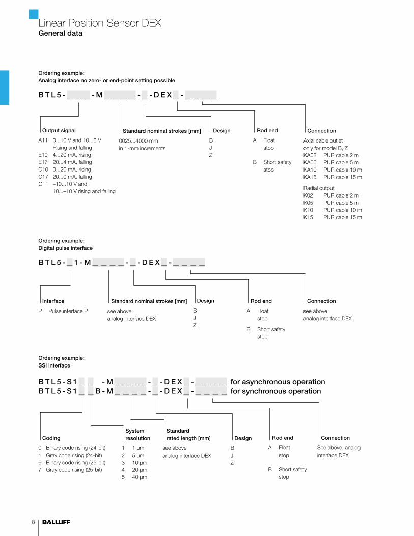
Ordering example:
Analog interface no zero- or end-point setting possible
B T L 5 - _ _ _ - M _ _ _ _ - _ - D E X _ - _ _ _ _
Ordering example:
SSI interface
B T L 5 - S 1 _ _ - M _ _ _ _ - _ - D E X _ - _ _ _ _ for asynchronous operation
B T L 5 - S 1 _ _ B - M _ _ _ _ - _ - D E X _ - _ _ _ _ for synchronous operation
Standard
rated length [mm]
see above
analog interface DEX
Connection
Axial cable outlet
only for model B, Z
KA02 PUR cable 2 m
KA05 PUR cable 5 m
KA10 PUR cable 10 m
KA15 PUR cable 15 m
Radial output
K02 PUR cable 2 m
K05 PUR cable 5 m
K10 PUR cable 10 m
K15 PUR cable 15 m
Connection
See above, analog
interface DEX
Rod end
A Float
stop
B Short safety
stop
Rod end
A Float
stop
B Short safety
stop
System
resolution
1 1 μm
2 5 μm
3 10 μm
4 20 μm
5 40 μm
Output signal
A11 0...10 V and 10...0 V
Rising and falling
E10 4...20 mA, rising
E17 20...4 mA, falling
C10 0...20 mA, rising
C17 20...0 mA, falling
G11 –10...10 V and
10...–10 V rising and falling
Ordering example:
Digital pulse interface
B T L 5 - _ 1 - M _ _ _ _ - _ - D E X _ - _ _ _ _
Connection
see above
analog interface DEX
Interface
P Pulse interface P
Design
B
J
Z
Coding
0 Binary code rising (24-bit)
1 Gray code rising (24-bit)
6 Binary code rising (25-bit)
7 Gray code rising (25-bit)
Linear Position Sensor DEXGeneral data
Standard nominal strokes [mm]
0025...4000 mm
in 1-mm increments
Rod end
A Float
stop
B Short safety
stop
Standard nominal strokes [mm]
see above
analog interface DEX
Design
B
J
Z
Design
B
J
Z

www.balluff.com 9
Series Rod J-DEXC-TA12
Part number BTL5-_ _-M_ _ _ _-J-DEXC-TA12
Shock load 100 g/6 ms in accordance with EN 60068-2-27
Vibration 12 g, 10...2000 Hz as per EN 60068-2-6
Operating temperature –20...+80 °C for T5
Storage temperature –40...+100 °C outside of Ex zone
Degree of protection IP 68
Housing material Stainless steel 1.4301 (other materials on request)
Protective tube Stainless steel 1.4571
Pressure rating 600 bar max.
Connection Screw terminals
Cable entry Ex cable gland BTL-A-AD09-M-00EX or Ex installation pipe system
EMC testing
Radio interference emission EN 55016-2-3 (industrial and residential area)
Static electricity (ESD) EN 61000-4-2 Severity level 3
Electromagnetic fields (RFI) EN 61000-4-3 Severity level 3
Electrical fast transient bursts (BURST) EN 61000-4-4 Severity level 3
Conducted interference induced
by high-frequency fields
EN 61000-4-6 Severity level 3
Please order separately:
■ Floats, see page 14
■ Position markers,
see catalog "Linear Position
Sensing and Measurement"
Linear Position Sensor TA12General data
Please enter the code for the output signal, interface, coding,
system solution, software configuration, baud rate, rated length,
and connection in the part number.
Scope of delivery
■ Position Sensor
■ User's Guide
The TA12 has been specially developed
for use in potentially explosive atmospheres. The important demands
of the oil and gas industry for high reliability and ease of servicing
are combined in the TA12 system.
The TA12 comprises a robust flameproof Ex housing and an
electronics module that is easily accessible and exchanged for
servicing. Spare electronics modules can be ordered from
Balluff Service department.
Flameproofenclosure
Fields of application
■ Hydraulically or pneumatically actuated valves
■ Clutch travel monitoring for compressors
■ Level monitoring
■ Level control
■ Position sensing in hydraulic cylinders in Ex areas
Class I, Division 1, Groups A, B, C, and DClass II, Division 1, Groups E, F, and G; Class III T6 Ta=65°C, T5 Ta=80°C Type 4X/6P; IP 68Class I, Zone 1 AEx d IIC T6 Ta=65°C, T5 Ta=80°CClass I, Zone 1 Ex d IIC T6 Ta=65°C, T5 Ta=80°C
SIRA 11ATEX1104XIECEx SIR 11.0048X
C US
11-2411253X
II 1/2GDEx d IIC T6/T5 Ga/Gb Ta +65°C (T6) +80°C (T5)Ex t IIIC T85/T100°C Da IP 68 Ta +65°C (T85) +80°C (T100)
0518

10
Linear Position Sensor TA12General data
Ordering example:
Analog interface
B T L 5 - _ _ _ - M _ _ _ _ - J - D E X C - TA 1 2
BAM011R
Programming tool for zero point and end point
Connection
TA12 Internal thread 1/2" 14 NPT
Standard nominal strokes [mm]
0025...4000 mm
in 1-mm increments
Output signal
A51 0...10 V and 10...0 V
Rising and falling
E50 4...20 mA, rising
E57 20...4 mA, falling
C50 0...20 mA, rising
C57 20...0 mA, falling
G51 –10...10 V and
10...–10 V rising and falling
Model TA12, flange Ø 18 mm, pitch circle Ø 76.2 mm
Interface A (mm) B (mm) C (mm)
Analog A, E, C
Digital SSI
104.12 96.12 59.5
Profibus DP, CANopen 135.62 127.62 91
BAM011TCable gland 1/2"-14 NPT to M20 metric
Ø 15
M20 thread
1/2" NPT thread
Position encoder
Rated length = measuring range
Mounting surface
1/2" 14 NPT
Thread
(modified)
24.
0
41.0
9.5

www.balluff.com 11
Linear Position Sensor TA12General data
Ordering example:
CANopen interface
B T L 5 - H 1 _ _ - M _ _ _ _ - J - D E X C - TA 1 2
Ordering example:
Profibus DP interface
B T L 5 - T 1 _ 0 - M _ _ _ _ - J - D E X C - TA 1 2
Standard
rated length [mm]
Analog interface J-DEXC
Standard
rated length [mm]
Analog interface J-DEXC
Software configuration
1 1 × position and
1 × velocity
2 2 × position and
2 × velocity
Baud rate
0 1 Mbaud
1 800 kbaud
2 500 kbaud
3 250 kbaud
4 125 kbaud
5 100 kbaud
6 50 kbaud
7 20 kbaud
8 10 kbaud
Software configuration
1 1 × position and
1 × velocity
2 2 × position and
2 × velocity
Ordering example:
SSI interface
B T L 5 - S 1 _ _ - M _ _ _ _ - J - D E X C - TA 1 2 for asynchronous operationB T L 5 - S 1 _ _ - B - M _ _ _ _ - J - D E X C - TA 1 2 for synchronous operation
Connection
TA12 Internal thread 1/2" 14 NPT
Standard
rated length [mm]
Analog interface J-DEXC
System
resolution
1 1 μm
2 5 μm
3 10 μm
4 20 μm
5 40 μm
Coding
0 Binary code rising (24-bit)
1 Gray code rising (24-bit)
6 Binary code rising (25-bit)
7 Gray code rising (25-bit)
Caution!
Before design, installation and startup please
familiarize yourself with the user's guide to be
found at www.balluff.com.
Connection
TA12 Internal thread 1/2" 14 NPT
Connection
TA12 Internal thread 1/2" 14 NPT

12
Dust protection zone22 II 3 D T 90°C X
Linear Position Sensor PEXGeneral data
Dust protection zone 22
Devices in these categories are intended for use in areas where
swirling dust is not expected to create an explosive atmosphere.
The probability is extremely small. Even if it were to occur, it would
be only for a short time.
A manufacturer's declaration confirms that sensors designated
II 3 D T 90°C X meet the requirements for electrical equipment for
use in areas with combustible dust.
*Not approved for USA and Canada.
Ordering example:
Digital pulse interface, for technical data refer to the user's guide
B T L 5 - P 1 - M _ _ _ _ - _ - P E X - K A 0 2
Connection
KA02 PUR cable 2 m
Standard nominal strokes [mm]
0025...5500 mm
in 1-mm increments
Design
B M18×1.5
Z 3/4" 16 UNF
Caution!
Before design, installation and startup please
familiarize yourself with the user's guide to be
found at www.balluff.com.
Note: Not all products are approved
for use in all global hazardous area
jurisdictions. Please consult Balluff
or refer to product technical
documentation to ensure that the
product certifications meet the
requirements of the region in which
the product will be used.

www.balluff.com 13
Ignition protection type"n" for zone 2
Linear Position Sensor NEXGeneral data
Ignition protection type "n", designated "EEx n"
Devices in this category are intended for use in areas where an
explosive atmosphere is not expected. The probability is extremely
small. Even if it were to occur, it would be only for a short time.
A manufacturer's declaration confirms that the indicated product
meets the requirements for electrical equipment in potentially
explosive areas. This designation combines multiple methods
of ignition protection.
*Not approved for USA and Canada.
Ordering example:
Model K
B T L 5 - _ _ _ - M _ _ _ _ - K - N E X - _ _ _ _
Ordering example:
Rod series
B T L 7 - _ _ _ - M _ _ _ _ - _ - N E X - _ _ _ _
Please enter code for output signal, rated length,
design and connection in the part number.
Please order separately:
■ Floats, see page 14
■ Position markers, see catalog
"Linear Position Sensing and Measurement"
Output signal
A11 0...10 V and 10...0 V
E10 4...20 mA, rising
E17 20...4 mA, falling
C10 0...20 mA, rising
C17 20...0 mA, falling
Standard
nominal strokes [mm]
0025...4500 mm
in 1-mm increments
Connection
SR32 with connector plug
K05 PUR cable 5 m
Standard
nominal strokes [mm]
0025...2000 mm
in 1-mm increments
Connection
S32 with connector plug
KA05 PUR cable 5 m
Design
B M18×1.5
Z 3/4" 16 UNF
CD M22×1.5 high-pressure
resistant
Output signal
A510 0...10 V and 10...0 V
E500 4...20 mA, rising
E570 20...4 mA, falling
C500 0...20 mA, rising
C570 20...0 mA, falling
Stainless steel

14
Hazardous Locations - Level MeasurementFloats
BAM0147
Cylindrical float, zone 0 permitted up to density ρ ≥ 0.7 g/cm3
Orientation:
Raised dimple on upper side of float
BAM0148
Cylindrical float, zone 0, density of float ρ = 0.85 g/cm3
for separation layer measurement
Orientation:
2 raised dimples on upper side of float
Floats (Zone 0)
32±
0,5
Ø20±0,5
Interface
A second float can be added to measure the position of the interface
between two liquids, such as oil and condensed water.
Suitable: BTL2-S-4414-4Z01-Ex.
BTL2-A-DH01-E-32-Ex
Spacer sleeve for the float:
BAM0147
BAM0148
BAM014A
The sleeve is included.
Caution!
Before design, installation and startup please
familiarize yourself with the user's guide to be
found at www.balluff.com.
www.balluff.com 15
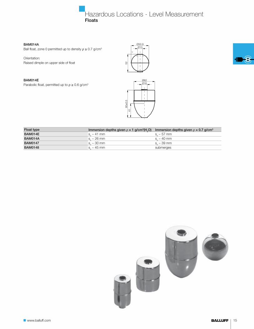
Hazardous Locations - Level MeasurementFloats
BAM014A
Ball float, zone 0 permitted up to density ρ ≥ 0.7 g/cm3
Orientation:
Raised dimple on upper side of float
BAM014E
Parabolic float, permitted up to ρ ≥ 0.6 g/cm3
Float type Immersion depths given ρ = 1 g/cm3(H2O) Immersion depths given ρ = 0.7 g/cm3
BAM014E ss ~ 41 mm s
s ~ 57 mm
BAM014A ss ~ 26 mm s
s ~ 40 mm
BAM0147 ss ~ 30 mm s
s ~ 39 mm
BAM0148 ss ~ 45 mm submerges

16
Hydraulic Cylinder Sensors, Ex ProtectedHigh pressure rated sensors, M12×1
up to 500 bar
17
10
18
61.5
78
M12x1
Ø10e77
4.1
17
10
17.9
61.5
78
M12x1
Ø10e7
7.4
3.7
Sensors with ATEX approval Category 3G
Devices in this category are designed for use in areas where explosive
atmospheres occur infrequently (Zone 2).
Caution!
Before design, installation and startup, please read the user's
guide found at www.balluff.com.
Size M12×1 M12×1
Installation type Flush Flush
Rated switching distance sn
1.5 mm 1.5 mm
Assured switching distance sa
0...1.2 mm 0...1.2 mm
Pressure range Oil-pressure resistant up to 350 bar Oil pressure resistant up to 500 bar
PNP, NO BHS004M BHS0031
Supply voltage US
10…30 V DC 10…30 V DC
Voltage drop Ud at I
e max. 1.5 V 2 V
Rated insulation voltage Ui
75 V DC 75 V DC
Rated operating current Ie
200 mA 200 mA
Output resistance Ra
33 kΩ 150 kΩ
Polarity reversal protected/transposition protected/short-circuit protected Yes/Yes/Yes Yes/Yes/Yes
Ambient temperature Ta
–25…+80 °C –25…+90 °C
Switching frequency f max. 1 kHz 2 kHz
Degree of protection as per IEC 60529 IP 68 per BWN Pr. 20 IP 68 per BWN Pr. 20
Approvals CE CE
Material Housing Stainless steel Stainless steel
Sensing surface EP EP
Sealing ring material/size/replacement part number FPM 70/5.85×2.4/636594 N70B200V/5.3×2.4/631753
Supporting ring material/size/replacement part number PTFE/5.3×2.4/705918 PTFE/5.3×2.4/705918
Connection M12 connector, 4-pin M12 connector, 4-pin
Not approved for USA and Canada
Note: Not all products are approved
for use in all global hazardous area
jurisdictions. Please consult Balluff
or refer to product technical
documentation to ensure that the
product certifications meet the
requirements of the region in which
the product will be used.

www.balluff.com 17
Hydraulic Cylinder Sensors, Ex ProtectedHigh pressure rated sensors, M12×1, M18×1
43.8
17
10
18
61.5
78
M12x1
Ø10e7
74.1
17
10
17.9
61.5
78
M12x1
Ø10e7
7.4
3.7
* Output current reduction as a function of
ambient temperature range
–25 °C +75 °C
200 mA
100 mA
+120 °C
M12×1 M12×1 M12×1 M18×1
Flush Flush Flush Flush
1.5 mm 1.5 mm 1.5 mm 1.5 mm
0...1.2 mm 0...1.2 mm 0...1.2 mm 0...1.2 mm
Oil pressure resistant up to 500 bar Oil pressure resistant up to 500 bar Oil pressure resistant up to 500 bar Oil pressure resistant up to 500 bar
BHS002W BHS001K BHS005P BHS004H
10…30 V DC 10…30 V DC 10…30 V DC 10…30 V DC
2 V 1.5 V 2.5 V 2 V
75 V DC 75 V DC 75 V DC 75 V DC
200 mA 200 mA 200 mA 200 mA
150 kΩ 33 kΩ 33 kΩ 150 kΩ
Yes/Yes/Yes Yes/Yes/Yes Yes/Yes/Yes Yes/Yes/Yes
–25…+80 °C –25…+80 °C –25…+120 °C* –25…+80 °C
2 kHz 1 kHz 400 Hz 2 kHz
IP 68 per BWN Pr. 20 IP 68 per BWN Pr. 20 IP 68 per BWN Pr. 20 IP 68 per BWN Pr. 20
CE CE CE CE
Stainless steel Stainless steel Stainless steel Stainless steel
EP EP Ceramic EP
N70B200V/5.3×2.4/631753 FPM 70/5.85×2.4/636594 FPM 80/6.75×1.78/149621 NBR 60-80/12.42x×1.78/642828
PTFE/5.3×2.4/705918 PTFE/5.3×2.4/705918 PTFE/10×7.0×1.8/150229 PTFE/15×12.2×0.7/642827
M12 connector, 4-pin M12 connector, 4-pin M12 connector, 4-pin M12 connector, 4-pin
Not approved for USA and Canada

18
Ignition protection type
„intrinsically safe“ used with
switching amplifier outside the
hazardous area
Inductive sensors to NAMUR
specification consist essentially
of an oscillator with a dampable
oscillator coil and a demodulator.
These high pressure-rated
sensors are used, for example,
in end-of-travel monitoring on
hydraulic cylinders or position
detection on valves.
They can be used in conjunction
with suitable isolating amplifiers,
such as from STAHL, in
potentially explosive systems
or spaces classified as Zone 1
or 2. The isolating amplifier
must be installed only outside
the explosive area.
Caution!
Before design, installation and
startup, please read the user‘s
guide found at www.balluff.com.
You must also observe the
requirements for the EC type
examination certificate.
3.7
7.7
3.7
7.4
Ignition protection type
“intrinsically safe”
Hydraulic Cylinder Sensors, ISNAMUR, high pressure rated sensors, M12×1
NAMUR High Pressure Rated
For additional data see
EC type examination certificate.
Not approved for USA and Canada
Sensors with Atex approval Category 2G
Devices in this category are designed for use in areas where
explosive atmospheres occur for short periods (Zone 1).
Caution!
Before design, installation and startup, please
read the user's guide found at www.balluff.com.
Size M12×1 M12×1
Installation type Flush Flush
Rated switching distance sn
1.5 mm 1.5 mm
Assured switching distance sa
0...1.2 mm 0...1.2 mm
Short Order Code BHS004L BHS004K
Rated operating voltage Ue
8.2 V DC 8.2 V DC
Supply voltage US
7.7...9 V DC 7.7...9 V DC
Rated insulation voltage Ui
75 V DC 75 V DC
Current
consumption at
sr = 0 ≤ 1 mA ≤ 1 mA
sr = ∞ ≥ 4 mA ≥ 4 mA
Rated series resistance RV
1000 Ω 1000 Ω
Permissible series resistance RV
550...1100 Ω 550...1100 Ω
Output signal: NAMUR
Fully undamped
Fully damped
Current change
(no trigger response)
≥ 4 mA
≤ 1 mA
Current change
(no trigger response)
≥ 4 mA
≤ 1 mA
Polarity reversal protected < 9 V Yes Yes
Ambient temperature Ta
–25...+70 °C –25...+70 °C
Switching frequency f 1 kHz 1 kHz
Degree of protection per IEC 60529 IP 68 per BWN Pr. 20 IP 68 per BWN Pr. 20
Material Housing Stainless steel Stainless steel
Sensing surface POM POM
Connection M12 connector,
4-pin
M12 connector,
4-pin
O-ring/spare part number 5.85×2.4/636594 5.85×2.4/636594
Support ring/spare part number 10×5.9×1/705918 10×5.9×1/705918
Pressure rated (hydraulic) up to 500 bar 500 bar
Effective internal capacitance ≤ 30 nF ≤ 30 nF
Effective internal inductance ≤ 0.5 mH ≤ 0.5 mH
Maximum input power Pi
200 mW 200 mW
Approvals
Conformity to standards EN 60079-0:2004
EN 50020:2002
EN 60079-0:2004
EN 50020:2002
EC type examination certificate PTB 01 ATEX 2207 X PTB 01 ATEX 2207 X
Designation EX II 2 G EX ia IIC T6 EX II 2 G EX ia IIC T6

www.balluff.com 19
Hydraulic Cylinder Sensors, ISNAMUR, isolating amplifiers
The isolating amplifier with relay output serves as the interface
between electrical signals from the hazardous area and the
non-hazardous area.
The input signals from NAMUR-sensors are converted using relay
switching contacts-at the outputs. Input, output and auxiliary power
circuits are galvanically isolated. An energy barrier prevents
dangerous levels of power from reaching the sensor.
Caution!
Before design, installation and startup, please read the
operating manual found at www.balluff.com.
You must also observe the requirements for
the EC type examination certificate.
Wiring diagrams
Hazardous Area
Non-Hazardous Area
STAHL 9170/20-12-11S
STAHL 9170/20-12-21S
For safety and other data see
EC type examination certificate.
Not approved for USA and Canada
Style 99×17.6×114.5 mm DIN 99×17.6×114.5 mm DIN
Short Order Code FHW004P FHW004R
Input NAMUR-specification NAMUR-specification
Output relay 2-channel, 1 converter 2-channel, 1 converter
Switching voltage 250 V AC Switching voltage 250 V AC
Switching current 4 A AC Switching current 4 A AC
Switching capacity 50 W/1000 VA Switching capacity 50 W/1000 VA
Function change via switch via switch
Supply voltage US
24 V DC 120...230 V AC
Ambient temperature Ta –20...+60 °C –20...+60 °C
Relative humidity ≤ 95 %, no condensation ≤ 95 %, no condensation
Approvals
Designation EX II (1) GD [EEx ia] IIC/IIB and EX II 3 G EEx nAC II T4EC type examination certificate DMT 02 ATEX E 195 X
NAMUR Sensors
NAMUR Sensors

20
Proximity Sensors, ISNAMUR, Ø 6.5 mm, M8×1
NAMUR
Ignition protection type
“intrinsically safe”
Ignition protection type
„intrinsically safe“ used with
isolating amplifier outside
the hazardous area
Inductive sensors to NAMUR
specification consist essentially
of an oscillator with a dampable
oscillator coil and a demodulator.
These sensors can be used
in conjunction with suitable
isolating amplifiers such as from
STAHL in explosive systems or
zones (see ATEX-marking).
The isolating amplifier must be
installed only outside the
explosive area.
Caution!
Before design, installation and
startup, please read the user‘s
guide found at www.balluff.com.
You must also observe the
requirements for the EC type
examination certificate.
Wiring diagrams
BES G06.../M08... BES M12.../M18.../M30... Unicompact
Shield
1 Connected to NAMUR-isolating amplifier
2 Connected to NAMUR- isolating amplifier
5 Connector body potential compensation
*Power restriction when using an approved intrinsically
safe isolating amplifier
Sensors in accordance with marking
For use in Zone 1 or Zone 20.
Size Ø 6.5 mm M8×1
Installation type Flush Flush
Rated switching distance sn
1 mm 1 mm
Assured switching distance sa
0.8 mm 0...0.8 mm
Short Order Code BES02ZR BES02ZT
Rated operating voltage Ue
8.2 V DC 8.2 V DC
Supply voltage US
7.7...9 V DC 7.7...9 V DC
Rated insulation voltage Ui
75 V DC 75 V DC
Output Signal: NAMUR
self-locking (undamped)
conductive (damped)
Current change
(no trigger response)
≤ 1 mA
≥ 2.1 mA
Current change
(no trigger response)
≤ 1 mA
≥ 2.1 mA
Rated series resistance RV
1 kΩ 1 kΩ
Polarity reversal protected no* no*Ambient temperature T
a–20...+70 °C –20...+70 °C
Switching frequency f 2 kHz 2 kHz
Function indicator No No
Degree of protection per IEC 60529 IP 67 IP 67
Material Housing Brass-coated Brass-coated
Sensing surface PBT PBT
Possible installation variations
Connection 2 m PVC cable,
2×0.14 mm²
2 m PVC cable,
2×0.14 mm²
Maximum internal capacitance 80 nF 80 nF
Maximum internal inductance 0.07 mH 0.07 mH
Connected to approved intrinsically safe U = 15 V U = 15 V
circuits with the highest values I = 50 mA I = 50 mA
P = 120 mW P = 120 mW
Approvals
Conformity to standards EN 50014:1997+A1+A2
EN 50020
EN 50014:1997+A1+A2
EN 50020
EC type examination certificate. BVS 05 ATEX E 163
PTB 05 ATEX 2075
BVS 05 ATEX E 163
PTB 05 ATEX 2075
Designation Ex II 2G EEx ia IIC T6
Ex II 1D Ex iaD 20 T90°CEx II 2G EEx ia IIC T6
Ex II 1D Ex iaD 20 T90°C
Not approved for USA and Canada

www.balluff.com 21
Proximity Sensors, ISNAMUR, M12×1, M18×1, M30×1.5, 40×40 mm
Permissible installation variations for Unicompact
Fig. 1 Fig. 2 Fig. 3 Fig. 4 Fig. 5 Fig. 6
M12×1 mm M18×1 mm M30×1.5 mm 40×40×66 mm Unicompact 40×40×66 mm Unicompact
Flush Flush Flush Flush Non flush
4 mm 8 mm 15 mm 20 mm 35 mm
0...3.2 mm 0...6.5 mm 0...12.2 mm 0...16.2 mm 0...28.4 mm
BES02ZU BES02ZW BES02ZY BES02ZZ BES0300
8.2 V DC 8.2 V DC 8.2 V DC 8.2 V DC 8.2 V DC
7.7...9 V DC 7.7...9 V DC 7.7...9 V DC 7.7...9 V DC 7.7...9 V DC
75 V DC 75 V DC 75 V DC 75 V DC 75 V DC
Current change
(no trigger response)
≤ 1 mA
≥ 2.1 mA
Current change
(no trigger response)
≤ 1 mA
≥ 2.1 mA
Current change
(no trigger response)
≤ 1 mA
≥ 2.1 mA
Current change
(no trigger response)
≤ 1 mA
≥ 2.1 mA
Current change
(no trigger response)
≤ 1 mA
≥ 2.1 mA
1 kΩ 1 kΩ 1 kΩ 1 kΩ 1 kΩ
no* no* no* no* no*–25...+70 °C –25...+70 °C –25...+70 °C –25...+70 °C –25...+70 °C
700 Hz 400 Hz 100 Hz 200 Hz 100 Hz
LED No No No No
IP 67 IP 67 IP 67 IP 67 IP 67
Brass-coated Brass-coated Brass-coated PPE/PPS PPE/PPS
PBT PBT PBT PBT PBT
Image 1...6 Image 3...6
M12 connector, 4-pin M12 connector, 4-pin M12 connector, 4-pin M12 connector, 5-pin M12 connector, 5-pin
210 nF 200 nF 230 nF 250 nF 220 nF
0.115 mH 0.19 mH 0.21 mH 0.45 mH 0.71 mH
U = 15 V U = 15 V U = 15 V U = 15 V U = 15 V
I = 50 mA I = 50 mA I = 50 mA I = 50 mA I = 50 mA
P = 120 mW P = 120 mW P = 120 mW P = 120 mW P = 120 mW
EN 50014:1997+A1+A2
EN 50020
EN 50014:1997+A1+A2
EN 50020
EN 50014:1997+A1+A2
EN 50020
EN 50014:1997+A1+A2
EN 50020
EN 50014:1997+A1+A2
EN 50020
BVS 05 ATEX E 162 X BVS 05 ATEX E 162 X BVS 05 ATEX E 162 X BVS 05 ATEX E 162 X BVS 05 ATEX E 162 X
Ex II 2G EEx ia IIC T6
Ex II 1D Ex iaD 20 T90°CEx II 2G EEx ia IIC T6
Ex II 1D Ex iaD 20 T90°CEx II 2G EEx ia IIC T6
Ex II 1D Ex iaD 20 T90°CEx II 2G EEx ia IIC T6
Ex II 1D Ex iaD 20 T90°CEx II 2G EEx ia IIC T6
Ex II 1D Ex iaD 20 T90°CNot approved for USA and Canada

22

Balluff North AmericaFlorence, Kentucky USA
Balluff’s Florence, Kentucky United States headquarters is located
just south of Cincinnati, Ohio. Our customers are in industries such
as automotive, machine tool, robotics, injection molding, packaging,
material handling, and more.
In addition to sales, marketing, and logistic functions, this facility
manufactures Micropulse® magnetostrictive linear position sensors
and warehouses over 60,000 products.
Great Britain Greece Hong Kong HungaryIceland India Indonesia Iran
Ireland Israel Italy Japan KoreaKuwait Malaysia Mexico
NetherlandsNew Zealand NorwayOman Pakistan Philippines Poland Portugal
Qatar Romania RussiaSaudi Arabia Singapore Slovakia Slovenia South Africa
Argentina Australia Austria Belarus Belgium Brazil Bulgaria Canada
China Columbia Croatia Czech Republic Denmark Finland France Germany
Spain Sweden Switzerland Thailand Taiwan Turkey USA Venezuela
www.balluff.com 23
The Balluff Global Network
Object Detection
Linear Position Sensing and Measurement
Fluid Sensors
Industrial Identification
Industrial Networking and Connectivity
Accessories
Systems and Services
USA Balluff Inc.
8125 Holton Drive
Florence, KY 41042
Phone: (859) 727-2200
Toll-free: 1-800-543-8390
Fax: (859) 727-4823
E-Mail: [email protected]
Canada Balluff Canada, Inc.
2840 Argentia Road, Unit #2
Mississauga, Ontario L5N 8G4
Phone: (905) 816-1494
Toll-free: 1-800-927-9654
Fax: (905) 816-1411
E-Mail: [email protected]
www.balluff.com
Mexico Balluff de México SA de CV
Anillo Vial II Fray Junípero Serra No. 4416
Colonia La Vista Residencial.
Querétaro, Qro. CP76146
Phone: (++52 442) 212-4882
Fax: (++52 442) 214-0536
E-Mail: [email protected]
Doc. no. 923961/Mat. no. 248454 EN
G15; Product specifications, availability, and
pricing are subject to change without notice.


![4 Prinsip Position Sensor [Compatibility Mode]](https://img.pdfslide.net/doc/110x75/577cd3df1a28ab9e7897aff4/4-prinsip-position-sensor-compatibility-mode.jpg)