Embed Size (px)
Citation preview
1
POST AND FRAME STRUCTURES (Pole Barns)
Post and frame structures. The following requirements serve as minimum standards for post and frame structures within all of the following structural limitations:
1. Residential accessory structures 2. Single story 3. Metal roof on purlins with bracing and metal wall panels on girts, with bracing, or in lieu of
bracing provide solid exterior structural sheathing 4. No attic storage 5. Maximum building width of 36 feet (provide engineer’s review for structure if more than 36 foot in width) 6. Maximum wall height of 16 feet (provide engineer’s review for structure over 12 foot and above in height) 7. Maximum “mean” roof height of 20 feet 8. Maximum post spacing of 8 feet
Post and frame structures and portions thereof outside the above structural limitations of this standard shall be accompanied by structural calculations as required by the residential building official or shall comply with the structural design requirements of section R301.1.3 of the 2015 Michigan Residential Code.
Definition. Post and frame structures consist of primary members (posts, beams and single span trusses or ceiling joists and rafters) and secondary members (roof purlins, wall girts, bracing and sheathing) where all loads are transmitted from the sheathing and the secondary members to the primary members which transfer them to the ground through vertical posts bearing on footings embedded in the soil.
Footings & Foundations. Footings and foundations shall comply with applicable provisions of Section R401 of the 2015 MRC. Post frame structures shall have poured in- place concrete footings installed below all posts. The top of the footing shall be a minimum of 42 inches below finished grade and have footing diameters complying with the following tables based on soil conditions at the site and calculated weight bearing on the posts.
GW, GP soils (Sandy gravel and/or gravel) Soil bearing capacity = 3,000 psf. Hole dia. Equiv. s.f. Allow. bearing (lbs)
12” dia. .785 sf. 2,335 16” dia. 1.395 sf. 4,185 18” dia. 1.766 sf. 5,298 20” dia. 2.18 sf. 6,540 24” dia. 3.14 sf. 9,420 28” dia. 4.273 sf. 12,819
Tables continued page 2
2
SW,SP,SM,SC,GM and GC soils (sand, silty sand, clayey sand, silty gravel, and clayey gravel) Soil bearing capacity = 2,000 psf.
Hole dia. Equiv. s.f. Allow. bearing (lbs) 12” dia. .785 sf. 1,570 16” dia. 1.395 sf. 2,790 18” dia. 1.766 sf. 3,532 20” dia. 2.18 sf. 4,360 24” dia. 3.14 sf. 6,280 28” dia. 4.273 sf. 8,546
CL, ML, MH and CH soils (Clay, sandy, silty clay, clayey silt, silt and sandy siltclay) Soil bearing capacity = 1,500 psf.
Hole dia. Equiv. s.f. Allow. bearing (lbs) 12” dia. .785 sf. 1,177 16” dia. 1.395 sf. 2,092 18” dia. 1.766 sf. 2,649 20” dia. 2.18 sf. 3,270 24” dia. 3.14 sf. 4,710 28” dia. 4.273 sf. 6,409
Math equation to size post footings Weight on footing ÷ soil bearing capacity = required square foot size for a square footing. To convert to round: convert sq. ft. to inches by multiplying the square footing size x 144. Take the square inches of the area and divide by 3.14159. Take the square root of the result. This is the radius. Multiply the radius by 2 to get the required diameter of the round footing.
Minimum footing thickness should be 1/2 of the footing diameter unless calculations are provided.
Example: 9,429 lbs ÷ 1,500 = 6.28 sq. ft. x 144 = 904.32. ÷ by 3.14159 = 287.85. The √ of 287.85 is 16.96 inches. This is the radius. 16.96 inches x 2 = 33.94 inches = required footing diameter. Column and wall construction. Columns shall be three (3) ply unspliced, reinforced spliced or solid wood and shall not be less than 6 inch by 6 inch nominal size. Columns shall comply with the requirements of Section R317 of the 2015 MRC (Protection of Wood) and shall be restrained to prevent lateral displacement.
Column uplift protection: Columns shall have uplift protection by one of the following methods:
1. Two 2x6x12 inch column uplift protection blocks attached to each side of the base of the column. The column uplift protection blocks must be placed horizontally, attached per Table 5 and comply with Section R317; or
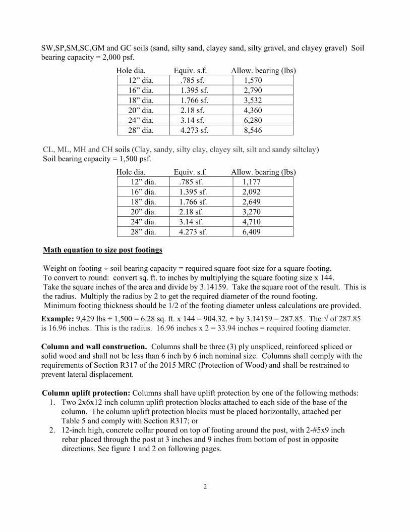
2. 12-inch high, concrete collar poured on top of footing around the post, with 2-#5x9 inch rebar placed through the post at 3 inches and 9 inches from bottom of post in opposite directions. See figure 1 and 2 on following pages.
3
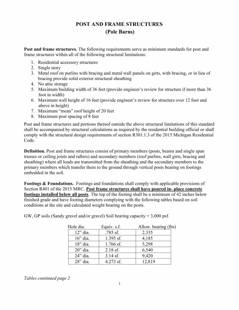
EXAMPLE CROSS SECTION
Figure 1 Post and frame wall section.
No scale
4
Figure 2
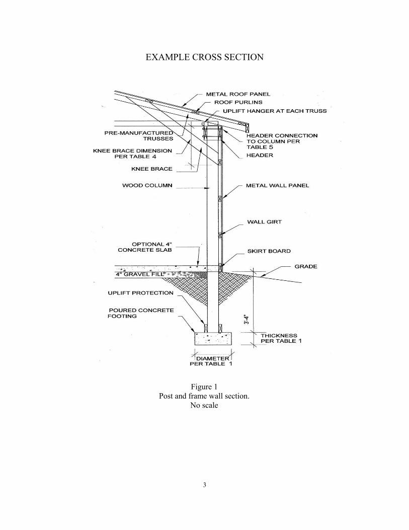
TYPICAL POLE BARN STRUCTURE
A=area (sq. ft.)
Figuring calculated loads on footings is based on the square foot area ½ the distance between the posts and the roof area directly above. Calculated snow loads (25-35 psf) + roof dead weight (20 psf) + wall dead weight (15 psf). Example: 30 psf snow load + 20 psf roof load + 15 psf wall load x Area (120 snow= 3,600 + 120 roof=2,400 + 96 wall = 1,440) for a total of 7,440 on each post. Posts would need to be sized accordingly. Footings sized accordingly or reduce distances between posts to reduce calculated loads on posts and footings based on soil conditions.
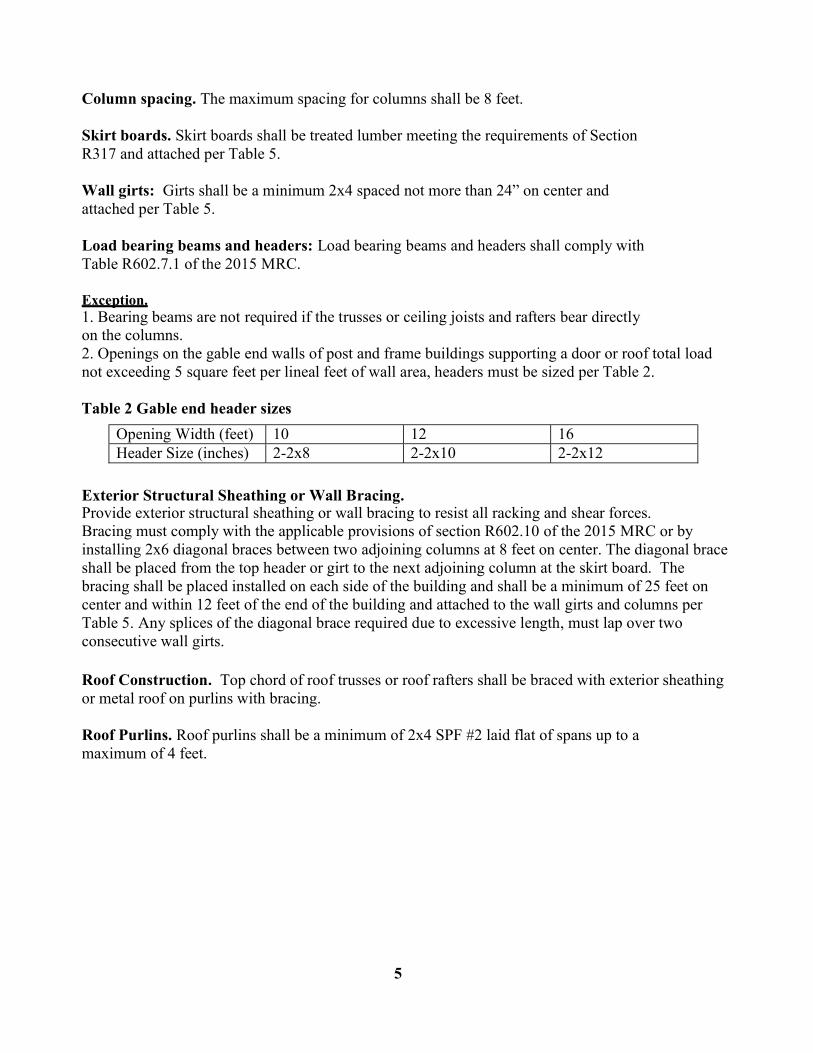
Column spacing. The maximum spacing for columns shall be 8 feet.
Skirt boards. Skirt boards shall be treated lumber meeting the requirements of Section R317 and attached per Table 5.
Wall girts: Girts shall be a minimum 2x4 spaced not more than 24” on center and attached per Table 5.
Load bearing beams and headers: Load bearing beams and headers shall comply with Table R602.7.1 of the 2015 MRC. Exception. 1. Bearing beams are not required if the trusses or ceiling joists and rafters bear directly on the columns. 2. Openings on the gable end walls of post and frame buildings supporting a door or roof total load not exceeding 5 square feet per lineal feet of wall area, headers must be sized per Table 2.
Table 2 Gable end header sizes
Opening Width (feet) 10 12 16 Header Size (inches) 2-2x8 2-2x10 2-2x12
Exterior Structural Sheathing or Wall Bracing. Provide exterior structural sheathing or wall bracing to resist all racking and shear forces. Bracing must comply with the applicable provisions of section R602.10 of the 2015 MRC or by installing 2x6 diagonal braces between two adjoining columns at 8 feet on center. The diagonal brace shall be placed from the top header or girt to the next adjoining column at the skirt board. The bracing shall be placed installed on each side of the building and shall be a minimum of 25 feet on center and within 12 feet of the end of the building and attached to the wall girts and columns per Table 5. Any splices of the diagonal brace required due to excessive length, must lap over two consecutive wall girts.
Roof Construction. Top chord of roof trusses or roof rafters shall be braced with exterior sheathing or metal roof on purlins with bracing.
Roof Purlins. Roof purlins shall be a minimum of 2x4 SPF #2 laid flat of spans up to a maximum of 4 feet.
5
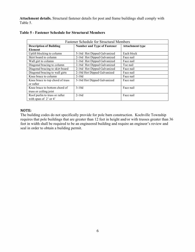
Attachment details. Structural fastener details for post and frame buildings shall comply with Table 5.
Table 5 - Fastener Schedule for Structural Members
NOTE: The building codes do not specifically provide for pole barn construction. Kochville Township requires that pole buildings that are greater than 12 feet in height and/or with trusses greater than 36 feet in width shall be required to be an engineered building and require an engineer’s review and seal in order to obtain a building permit.
6
Fastener Schedule for Structural Members Description of Building Element
Number and Type of Fastener Attachment type
Uplift blocking to column 5-16d Hot Dipped Galvanized Each block Skirt board to column 2-16d Hot Dipped Galvanized Face nail Wall girt to column 2-16d Hot Dipped Galvanized Face nail Diagonal bracing to column 2-16d Hot Dipped Galvanized Toe nail Diagonal bracing to skirt board 2-16d Hot Dipped Galvanized Face nail Diagonal bracing to wall girts 2-10d Hot Dipped Galvanized Face nail Knee brace to column 2-10d Face nail Knee brace to top chord of truss or rafter
3-16d Hot Dipped Galvanized Face nail
Knee brace to bottom chord of truss or ceiling joist
3-10d Face nail
Roof purlin to truss or rafter with span of 2’ or 4’
2-16d Face nail
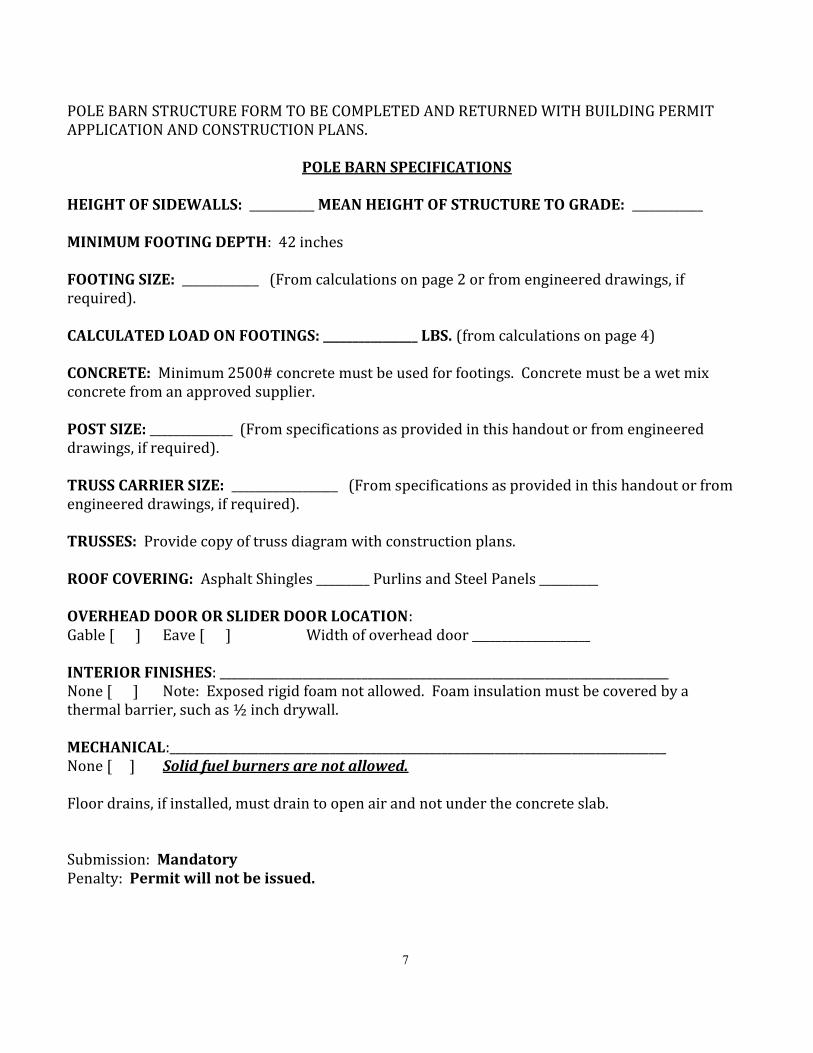
POLE BARN STRUCTURE FORM TO BE COMPLETED AND RETURNED WITH BUILDING PERMIT APPLICATION AND CONSTRUCTION PLANS.
POLE BARN SPECIFICATIONS HEIGHT OF SIDEWALLS: ___________ MEAN HEIGHT OF STRUCTURE TO GRADE: ____________ MINIMUM FOOTING DEPTH: 42 inches FOOTING SIZE: _____________ (From calculations on page 2 or from engineered drawings, if required). CALCULATED LOAD ON FOOTINGS: ________________ LBS. (from calculations on page 4) CONCRETE: Minimum 2500# concrete must be used for footings. Concrete must be a wet mix concrete from an approved supplier. POST SIZE: ______________ (From specifications as provided in this handout or from engineered drawings, if required). TRUSS CARRIER SIZE: __________________ (From specifications as provided in this handout or from engineered drawings, if required). TRUSSES: Provide copy of truss diagram with construction plans. ROOF COVERING: Asphalt Shingles _________ Purlins and Steel Panels __________ OVERHEAD DOOR OR SLIDER DOOR LOCATION: Gable [ ] Eave [ ] Width of overhead door ____________________ INTERIOR FINISHES: ____________________________________________________________________________ None [ ] Note: Exposed rigid foam not allowed. Foam insulation must be covered by a thermal barrier, such as ½ inch drywall. MECHANICAL:____________________________________________________________________________________ None [ ] Solid fuel burners are not allowed. Floor drains, if installed, must drain to open air and not under the concrete slab. Submission: Mandatory Penalty: Permit will not be issued. 7