Embed Size (px)
Citation preview

1
Technical noTe
www.aefac.org.au
Post-installed RebaR ConneCtions
Ver. 1.0November, 2017
1
www.aefac.org.au
1. Scope
This Technical Note provides recommendations on design of post-installed rebar using adhesives in drilled holes in concrete for tensile load. This Technical Note covers the design for development length to achieve the characteristic yield strength of rebar. It also covers the determination of tensile capacity of post installed rebars to develop a stress less than the characteristic yield strength of rebar.
The basis of this Technical Note are EAD [1], ETAG 001 [2], EOTA TR 023 [3] and AS 3600 [4]. EAD, ETAG 001 and TR 023 are used for the prequalification of post-installed rebar system and AS 3600 is used for the design for development length and tensile capacity.
The provisions of AS 3600 are for cast-in rebar and do not address the behavior of post-installed rebar. The purpose of this Technical Note is to ensure that post-installed rebar performs in a similar manner to cast-in rebar (in terms of load transfer and load-displacement behaviour). Since a layer of adhesive is present between the rebar and the substrate in the post-installed rebar application, the overall behavior of the system is also dependent on the properties of the adhesive. Thus, in order to use this Technical Note, the post-installed rebar adhesive system must be prequalified according to EOTA TR 023 to ensure its suitability for this application. The ETA (European Technical Assessment) based on TR 023 is referred to herein as ETA–TR 023. This is to distinguish the additional prequalification for the ETA which is issued based on EAD / ETAG 001 and referred to herein as just ETA which is used for designs according to SA TS 101:2015[5].
The product ETA–TR 023 for post-installed rebar system based on TR 023 is different from the product ETA for adhesive anchors issued based on EAD/ETAG 001 testing and evaluation method. The ETA–TR 023 specifically provides the design ultimate
AEFAC Technical Note
on
Post-Installed Rebar Connections

2
Technical noTe: PosT-insTalled RebaR connecTions
www.aefac.org.au
bond strength (also called bond resistance) values (fbd) which are different from design bond strength values derived from the characteristic bond strength values (τRk) in the ETA for adhesive anchors. For post-installed rebar connections, the design ultimate bond strength (fbd) as given in ETA–TR 023 are used.
In general, the design ultimate bond strength value in the ETA–TR 023 is lower than the bond strength in the ETA (based on EAD/ETAG 001). The lower value of bond strength must be considered to scale the development length obtained from equation (1) in Section 5 of this Technical Note. Please refer to Example 1 for fbd of 2.5MPa.
The Technical Note covers straight deformed reinforcing bars with diameter greater than or equal to 10mm and concrete with minimum compressive strength of 20MPa with upper limits for concrete strength and rebar as defined by the relevant ETA–TR 023.
This Technical Note covers static loading and does not cover seismic, fatigue and fire actions. It covers post-installed rebars installed in dry and wet concrete (not in flooded holes).
The recommendations provided in this Technical Note are of general nature. For product specific detailed information, advice from the supplier/manufacturer should be sought.
For post-installed rebar connections, the required hole depth may be large and hence the installation quality is extremely important. The installation must be carried out in accordance with the manufacturer’s installation instructions (MII). The installation should only be performed by competent personnel, either certified by AEFAC [6] or trained by anchor supplier for this specific application.
2. Terminology
The following terminologies and definitions are used in this Technical Note. Please refer to AEFAC Anchor Dictionary [7] for additional terminologies and definitions.
Anchor: a type of device that is post-installed into matured concrete or cast into concrete.
Competent person: A person who has acquired thorough training, qualification or experience, or a combination of these, the knowledge and skills to enable that person
3
Technical noTe: PosT-insTalled RebaR connecTions
www.aefac.org.au
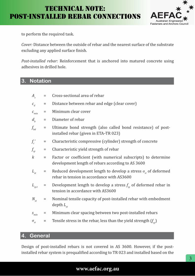
to perform the required task.
Cover: Distance between the outside of rebar and the nearest surface of the substrate excluding any applied surface finish.
Post-installed rebar: Reinforcement that is anchored into matured concrete using adhesives in drilled hole.
3. Notation
As = Cross-sectional area of rebar
cd = Distance between rebar and edge (clear cover)
cmin = Minimum clear cover
db = Diameter of rebar
fbd = Ultimate bond strength (also called bond resistance) of post-installed rebar (given in ETA–TR 023)
fc’ = Characteristic compressive (cylinder) strength of concrete
fsy = Characteristic yield strength of rebar
k = Factor or coefficient (with numerical subscripts) to determine development length of rebars according to AS 3600
Lst = Reduced development length to develop a stress σst of deformed rebar in tension in accordance with AS3600
Lsy.t = Development length to develop a stress fsy of deformed rebar in tension in accordance with AS3600
Nst = Nominal tensile capacity of post-installed rebar with embedment depth Lst
smin = Minimum clear spacing between two post-installed rebars
σst = Tensile stress in the rebar, less than the yield strength (fsy)
4. General
Design of post-installed rebars is not covered in AS 3600. However, if the post-installed rebar system is prequalified according to TR 023 and installed based on the

4
Technical noTe: PosT-insTalled RebaR connecTions
www.aefac.org.au
instructions reported in the product ETA–TR 023, the provisions given in AS 3600 can be used for post-installed rebar design within the scope describe in Section 1 of this Technical Note and the ETA–TR 023.
TR 023 is used in Europe for the prequalification and design of post-installed rebars and it refers to the concrete design code Eurocode 2 [8]. In this Technical Note, the design provisions of AS 3600 are adopted rather than Eurocode 2 to be used with ETA–TR 023.
The qualification process for post-installed rebar is included in TR 023 which also includes the intended application range of post installed rebar as reported in Figure 1.1 to 1.5 of TR 023 and also reproduced in the product ETA–TR 023.
5. Design of Post-installed Rebar Connection
Unlike Eurocode 2, AS 3600 does not explicitly use bond strength (fbd) in the formula to obtain the development length. If the design ultimate bond strength (fbd) in the relevant product ETA–TR 023 is less than the values stated in TR 023 and shown in Table 1, then the calculated development length from equation (1) needs to be increased in proportion to the ratio of the value given in TR 023 and the value from the ETA–TR 023 for the given strength of concrete (see Example 1).
Table 1: Design bond strength according to TR 023 without limitation.
S.N.Compressive strength of
concrete (MPa)Design ultimate bond strength
fbd (MPa)
1 20 2.3
2 25 2.7
3 32 3.2
4 40 3.7
5 45 4.0
6 50 4.3
Note:
Design ultimate bond strength (fbd) provided in this table are for rebar with diameter less than or equal to 32mm.
5
Technical noTe: PosT-insTalled RebaR connecTions
www.aefac.org.au
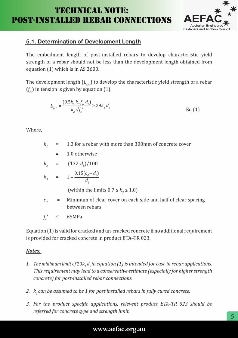
5.1. Determination of Development Length
The embedment length of post-installed rebars to develop characteristic yield strength of a rebar should not be less than the development length obtained from equation (1) which is in AS 3600.
The development length (Lsy.t) to develop the characteristic yield strength of a rebar (fsy) in tension is given by equation (1).
Lsy.t = (0.5k1 k3 fsy db)
≥ 29k1 db k2 √fc’ Eq (1)
Where,
k1 = 1.3 for a rebar with more than 300mm of concrete cover
= 1.0 otherwise
k2 = (132-db)/100
k3 = 1 − 0.15(cd − db)
db
(within the limits 0.7 ≤ k3 ≤ 1.0)
cd = Minimum of clear cover on each side and half of clear spacing between rebars
fc’ ≤ 65MPa
Equation (1) is valid for cracked and un-cracked concrete if no additional requirement is provided for cracked concrete in product ETA–TR 023.
Notes:
1. The minimum limit of 29k1 db in equation (1) is intended for cast-in rebar applications. This requirement may lead to a conservative estimate (especially for higher strength concrete) for post-installed rebar connections.
2. k1 can be assumed to be 1 for post installed rebars in fully cured concrete.
3. For the product specific applications, relevent product ETA–TR 023 should be referred for concrete type and strength limit.
6
Technical noTe: PosT-insTalled RebaR connecTions
www.aefac.org.au
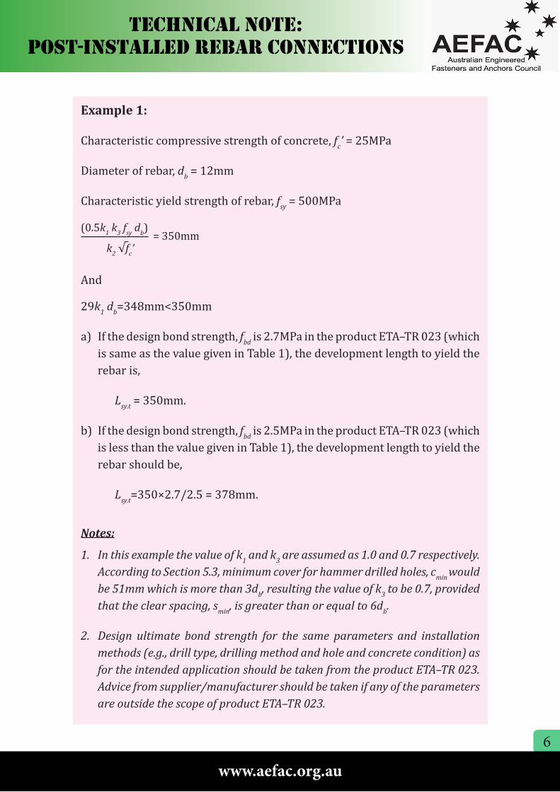
Example 1:
Characteristic compressive strength of concrete, fc’ = 25MPa
Diameter of rebar, db = 12mm
Characteristic yield strength of rebar, fsy = 500MPa
(0.5k1 k3 fsy db) = 350mm
k2 √fc’
And
29k1 db=348mm<350mm
a) If the design bond strength, fbd is 2.7MPa in the product ETA–TR 023 (which is same as the value given in Table 1), the development length to yield the rebar is,
Lsy.t = 350mm.
b) If the design bond strength, fbd is 2.5MPa in the product ETA–TR 023 (which is less than the value given in Table 1), the development length to yield the rebar should be,
Lsy.t=350×2.7/2.5 = 378mm.
Notes:
1. In this example the value of k1 and k3 are assumed as 1.0 and 0.7 respectively. According to Section 5.3, minimum cover for hammer drilled holes, cmin would be 51mm which is more than 3db, resulting the value of k3 to be 0.7, provided that the clear spacing, smin, is greater than or equal to 6db.
2. Design ultimate bond strength for the same parameters and installation methods (e.g., drill type, drilling method and hole and concrete condition) as for the intended application should be taken from the product ETA–TR 023. Advice from supplier/manufacturer should be taken if any of the parameters are outside the scope of product ETA–TR 023.
7
Technical noTe: PosT-insTalled RebaR connecTions
www.aefac.org.au
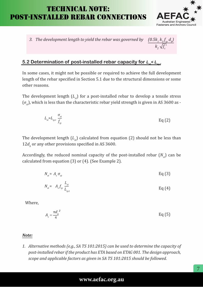
5.2 Determination of post-installed rebar capacity for Lst< Lsy.t
In some cases, it might not be possible or required to achieve the full development length of the rebar specified in Section 5.1 due to the structural dimensions or some other reasons.
The development length (Lst) for a post-installed rebar to develop a tensile stress (σst), which is less than the characteristic rebar yield strength is given in AS 3600 as -
Lst=Lsy.t
σst
fsy
Eq (2)
The development length (Lst) calculated from equation (2) should not be less than 12db or any other provisions specified in AS 3600.
Accordingly, the reduced nominal capacity of the post-installed rebar (Nst) can be calculated from equation (3) or (4). (See Example 2).
Nst = As σst Eq (3)
Nst = As
fsy
Lst
Lsy.t
Eq (4)
Where,
As =
πda² 4 Eq (5)
Note:
1. Alternative methods (e.g., SA TS 101:2015) can be used to determine the capacity of post-installed rebar if the product has ETA based on ETAG 001. The design approach, scope and applicable factors as given in SA TS 101:2015 should be followed.
3. The development length to yield the rebar was governed by (0.5k1 k3 fsy db)
k2 √fc’
8
Technical noTe: PosT-insTalled RebaR connecTions
www.aefac.org.au
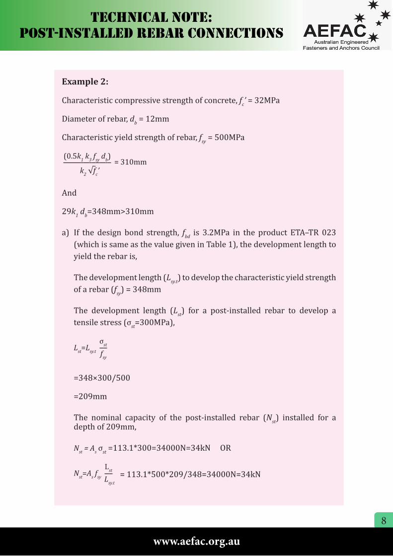
Example 2:
Characteristic compressive strength of concrete, fc’ = 32MPa
Diameter of rebar, db = 12mm
Characteristic yield strength of rebar, fsy = 500MPa
(0.5k1 k3 fsy db) = 310mm
k2 √fc’
And
29k1 db=348mm>310mm
a) If the design bond strength, fbd is 3.2MPa in the product ETA–TR 023 (which is same as the value given in Table 1), the development length to yield the rebar is,
The development length (Lsy.t) to develop the characteristic yield strength of a rebar (fsy) = 348mm
The development length (Lst) for a post-installed rebar to develop a tensile stress (σst=300MPa),
Lst=Lsy.t
σst
fsy
=348×300/500
=209mm
The nominal capacity of the post-installed rebar (Nst) installed for a depth of 209mm,
Nst = As σst =113.1*300=34000N=34kN OR
Nst=As
fsy
Lst
Lsy.t
= 113.1*500*209/348=34000N=34kN
9
Technical noTe: PosT-insTalled RebaR connecTions
www.aefac.org.au
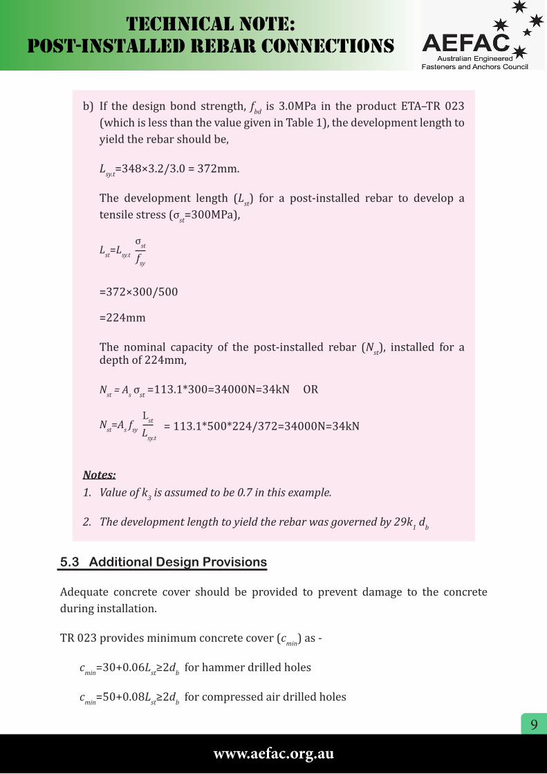
b) If the design bond strength, fbd is 3.0MPa in the product ETA–TR 023 (which is less than the value given in Table 1), the development length to yield the rebar should be,
Lsy.t=348×3.2/3.0 = 372mm.
The development length (Lst) for a post-installed rebar to develop a tensile stress (σst=300MPa),
Lst=Lsy.t
σst
fsy
=372×300/500
=224mm
The nominal capacity of the post-installed rebar (Nst), installed for a depth of 224mm,
Nst = As σst =113.1*300=34000N=34kN OR
Nst=As
fsy
Lst
Lsy.t
= 113.1*500*224/372=34000N=34kN
Notes:1. Value of k3 is assumed to be 0.7 in this example.
2. The development length to yield the rebar was governed by 29k1 db
5.3 Additional Design Provisions
Adequate concrete cover should be provided to prevent damage to the concrete during installation.
TR 023 provides minimum concrete cover (cmin) as -
cmin=30+0.06Lst≥2db for hammer drilled holes
cmin=50+0.08Lst≥2db for compressed air drilled holes
10
Technical noTe: PosT-insTalled RebaR connecTions
www.aefac.org.au
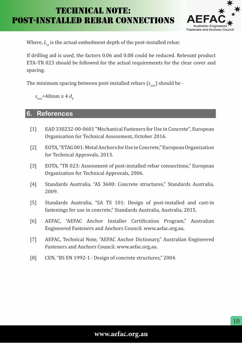
Where, Lst is the actual embedment depth of the post-installed rebar.
If drilling aid is used, the factors 0.06 and 0.08 could be reduced. Relevant product ETA–TR 023 should be followed for the actual requirements for the clear cover and spacing.
The minimum spacing between post-installed rebars (smin) should be -
smin=40mm ≥ 4 db
6. References
[1] EAD 330232-00-0601 "Mechanical Fasteners for Use in Concrete", European Organisation for Technical Assessment, October 2016.
[2] EOTA, “ETAG 001: Metal Anchors for Use in Concrete,” European Organization for Technical Approvals, 2013.
[3] EOTA, “TR 023: Assessment of post-installed rebar connections,” European Organization for Technical Approvals, 2006.
[4] Standards Australia, “AS 3600: Concrete structures,” Standards Australia, 2009.
[5] Standards Australia, “SA TS 101: Design of post-installed and cast-in fastenings for use in concrete,” Standards Australia, Australia, 2015.
[6] AEFAC, “AEFAC Anchor Installer Certification Program,” Australian Engineered Fasteners and Anchors Council. www.aefac.org.au.
[7] AEFAC, Technical Note, “AEFAC Anchor Dictionary,” Australian Engineered Fasteners and Anchors Council. www.aefac.org.au.
[8] CEN, “BS EN 1992-1 : Design of concrete structures,” 2004.

11
www.aefac.org.au
Disclaimer: The information provided in this Technical Note is intended for general guidance only, and in no way replaces the services of design engineers on particular projects or subjects. AEFAC and its board, constituent members, representatives or agents will not be liable for any claims or damages whatsoever resulting from use or reliance on information in this Technical Note.