Embed Size (px)
Citation preview

Technical Report WRD95042
Viewed at 20:02:43 on 17/02/2010 Page 1 of 30.
•
Power and Water Authority
I Matthews
Hydrogeologist
W1JYAGIBA CO~TIY GROUNDWATER
RESOlJRCE EV ALUA TION
Water Resources Division
Darwin NT
October 1995
Report 42/95D

Technical Report WRD95042
Viewed at 20:02:43 on 17/02/2010 Page 2 of 30.
• DISTRIBUTION LIST
LIST OF FIGURES
LIST OF TABLES
LIST OF ABBREVIATIONS
1. IN1RODUCTION
2. HYDROGEOLOGY
3. PREVIOUS DRILLINGIREHABILITATION
4. CURRENT INVESTIGATIONS
5. RECOMMEl'iDA TIONS
Numbulwar Homelands Council
Water Resources Division Library, Darwin
Water Resources Division Library, Alice Springs
Water Resources Division Hydrogeology Section
Author
CONTENTS
DISTRIBUTION LIST
2
3
2
2
1

Technical Report WRD95042
Viewed at 20:02:43 on 17/02/2010 Page 3 of 30.
• 1-
'")
, ~.
4.
5.
6.
Location Map
Community Plan and Possible Drill Locations
Composite Log - RN 9669
Composite Log - RN 9871
Composite Log - RN 9872
Typical Infiltration Gallery Design Suitable for Wuyagiba
LIST OF FIGURES
LIST OF TABLES
I. Water Quality Data
LIST OF ABBRE\;lATIONS
AHD Australian Height Datum
BGL below ground level
EC electrical conductivity
kIn kilometres
ID inside diameter
m metres
mgJL milligrams per litre
PVC polyvinylchloride
R.N Registered Number
SWL standing water level
TD total depth
!lS/cm rnicrosiemens per centimetre
Technical Report WRD95042
Viewed at 20:02:43 on 17/02/2010 Page 4 of 30.
1.0 INTRODUCTION
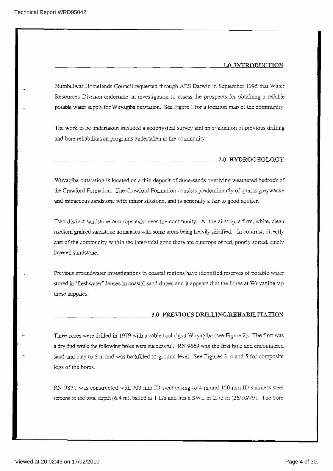
Numbulwar Homelands Council requested through AES Darwin in September 1995 that Water
Resources Division undertake an investigation to assess the prospects for obtaining a reliable
potable water supply for Wuyagiba outstation. See Figure I for a location map of the community.
The work to be undertaken included a geophysical survey and an evaluation of previous drilliIlg
and bore rehabilitation programs undertaken at the community.
2.0 HYDROGEOLOGY
Wuyagiba outstation is located on a thin deposit of dune-sands overlying weathered bedrock of
the Crawford Formation. The Crawford Formation consists predominantly of quartz greywacke
and micaceous sandstone with minor siltstone, and is generally a fair to good aquifer.
Two disti.l1ct sandstone outcrops exist near the community. At the airstrip, a fInn, white, clean
medium grained sandstone dominates with some areas teing heavily silicified. In contrast, directly
east of the community within the inter-tidal zone there are outcrops of red, poorly sorted, fmely
layered Sa...,dslone.
Previous groundwater investigations in coastal regions have identified reserves of parable water
stored in "freshwater" lenses in coastal sand dunes and it appears that the bores at Wuyagiba tap
these supplies.
3.0 PREviOUS DRILLING/REHABUJT ATION
Three bores were drilled in 1979 with a cable tool rig at Wuyagiba (see Figure 2). The fIrst was
a dry dud while the following holes were successful. Ri'\l9669 was the fIrst hole and encountered
sand and clav to 6 m and was backfilled to "round level. See Fi"ures 3, 4 and 5 for comnosite '" ....... '- ...
logs of the bores.
RN 9871 was constructed with 203 mm ID steel caSing to ..\ m and 150 mm ID stainless steel
screens to the tOtal depth (6.4 m), bailed at ! Lis and has a SW"L of 2.75 m (26110179). The bore

Technical Report WRD95042
Viewed at 20:02:43 on 17/02/2010 Page 5 of 30.
has been test pumped and has a maximum recommended yield of 0.7 Lis. The water quality is
potable (see Table 1 for individual ion analysis). Bore RN 9872 was bailed at 1.2 Lis and has
identical consu-uction and S\VL to RN 9871. The bore has been test pumped and has a
recommended maximum pumping rate of 0.7 Lis. Tne water is potable.
Bore Rc'l 9871 was originally equipped with a solar powered submersible pump until problems
with the bore forking occured in late 1994. WRB was requested to investigate the problems and
rehabilitate the bore. Sand, silt and tree roots were removed from the bore to the TD of 6.4 m and
the screens jetted. The yield was not significantly improved and the bore pumped on the fork at
0.03 Us. It was suggested that the bore was beyond rehabilitation due to siltation and corrosion
and should be equipped with a hand pump and be used as a standby bore. It was suggested at this
time that pumping equipment be tranferred to R.N 9872 and that this bore be used to supply the
community, at least in the short term. This was camed out, approximately 12 months ago.
4.0 CURRENT INVESTIGATION
A field visit to the community was undertaken on October 2,3 and 4. Bore RN 9871 is currently
equipped with a hand pump while RN 9872 is equipped wiu'J. a solar-powered Grundfos electric
submersible and pumps to an overhead tank, which was approximately one-third full at the time
of inspection.
The community consists of 5 houses and approximately 15 people reside there on a permanent
basis. Approximately 100 trees and 100 m2 oflawns are being irrigated. As such daily demand
could be expected to be up to 10 kL per day. A bore pumped at 0.3 Lis for 10 hours per day
would adequately supply the needs of the outstation.
The bores are located in the middle of the community, approximately 50 m down gradient from
the pit toilets. With the shallow SW'L and permeable strata in the area it is considered that the
bores are prone to bacteriological contamination. Optimally, lhe communities water supply should
be sourced from an area remote (>100 m) from any development. No bacteriological water
analyses have been undertaken.

Technical Report WRD95042
Viewed at 20:02:43 on 17/02/2010 Page 6 of 30.
From logging of the chips samples it is concluded that Rt"f 987! yields water from the contact
between the dune sands and the underlying weathered fme-grained red sandstone. The sandstone
is similar to that seen out-cropping on the shoreline directly east of the community.
Bore Rl"f 9872 appears to have attained the supply from a cemented sand with perhaps 20% shell
fragments. The two bores are only 10 m apart and it can only be assumed that Rl"f 9872 would
soon have struck the same red sandstone if drilling had continued. It is not known why drilling
ceased after onl y marginal supplies were attained, although the proximity to the ocean may have
been a faclOr.
A saline lake (evidenced by a salt crust and minimal vegetation) lies 2 kIn to the west of the
community. The EM-31 survey delineated areas of low conductiviry from approximately 30 m
west of the community through to close to the saline lake.
Due to the nature of the aquifer, there is a substantial area in wbich further investigation could take
place. Figure 2 shows a shaded area comprised of two sections, A and B.
Section A is located on the flat, low-lying area east of the high sand dune and north of the
community. As this area is topoglaphically similar to the current bores, depths to the aquifer
would be expected to be similar to the current bores. The main advantage in this location is that
an infIltration gallery could be installed by a back..hoe. See Figure 6 for the design of a typical
installation. Construction involves digging a trench (to about 5-6 m in this case) with a backhoe
and the gallery being lowered into place and then covered with sand. These syterns are efficient
at collecting groundwater due to the large open area within the aquifer and can operate
successfully with only small available drawdowns, as is the case at Wuyagiba. Water Resources
Branch can undertake the gallery design and supervise the installation if necessary. An extraction
system in this location would be distant enough from the communiry and not directly down
gradient of the toilets, minimising bacteriological concerns. It is expected that a year-round
pctable system could be constructed here. The gallery should be installed a least 20 m from any
trees as problems can be encountered with tree roots invading the system.
Alternatively, exploration could be conducted to the west of. or on top of. the high sand dune.
The disadvantage to this is that a drill rig would be required as the aquifer may be encountered
Technical Report WRD95042
Viewed at 20:02:43 on 17/02/2010 Page 7 of 30.
•
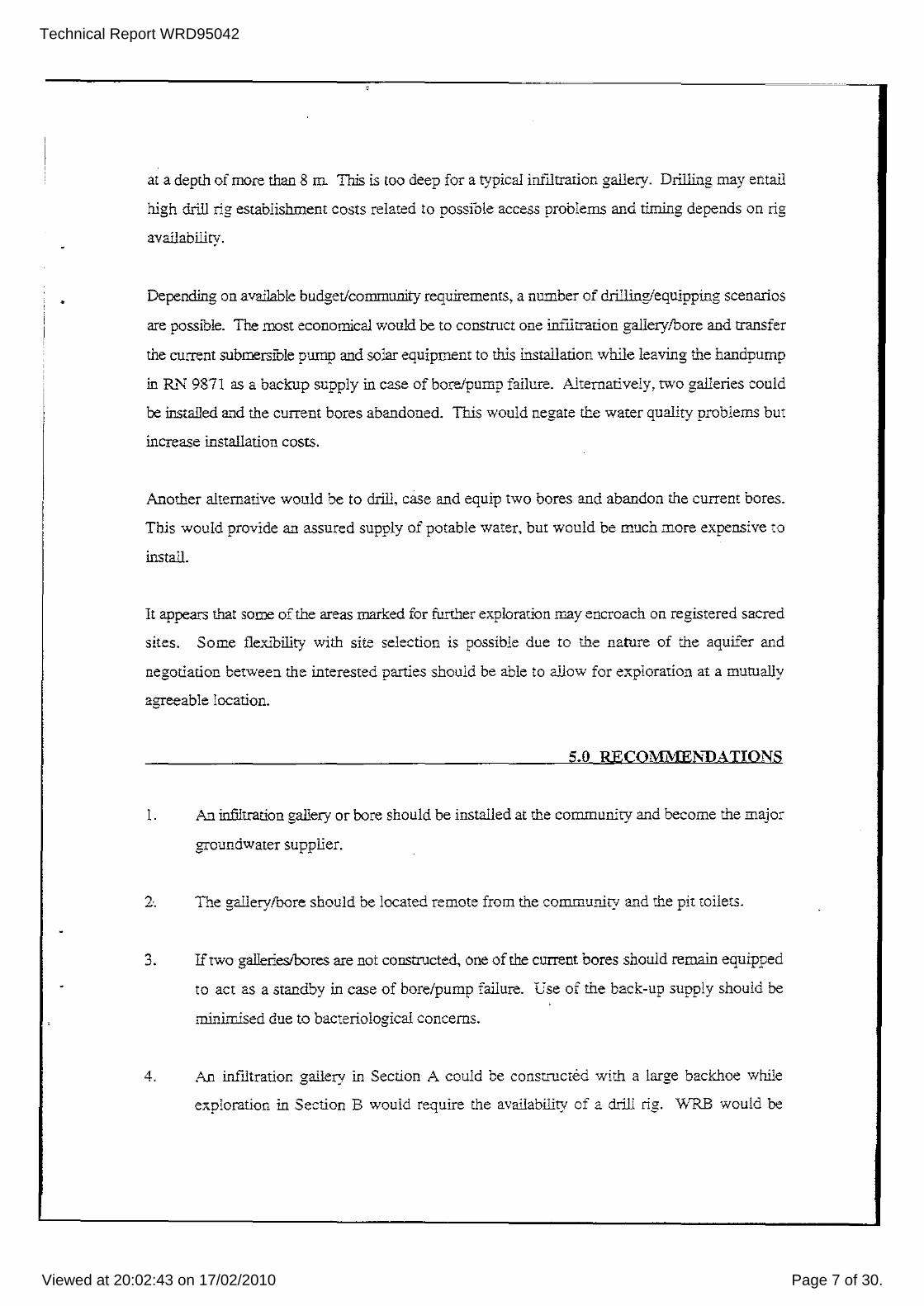
at a depth of more than 8 ill This is too deep for a typical infIltration gallery, Drilling may entail
high drill rig establishment costs related to possible access problems and timing depends on rig
availability.
Depending on available budget/community requirements, a number of drilling/equipping scenarios
are possible. The most economical would be to construct one infllrration gallerylbore and transfer
the current submersible pump and solar equipment to this installation while leaving the handpump
in R..!"l9871 as a backup supply in case of boreJpump failure. Alternatively. two galleries could
be installed and the current bores abandoned. This would negate the water quality problems but
increase installation costs.
Another alternative would be to drill, case and equip two bores and abandon the current bores.
This would provide an assured supply of potable water, but would be much more expensive to
install.
It appears that some of the areas marked for further exploration may encroach on registered sacred
sites. Some flexibility with site selection is possible due to the nature of the aquifer and
negotiation between the interested parties should be able to allow for exploration at a mutually
agreeable location.
5.0 RECOMME,NDATIONS
I. An infilrration gallery or bore should be installed at the communiry and become the major
groundwater supplier.
2·. The gallerylbore should be located remote from the community and the pit railets.
3. If two gallerieslbores are not constructed, one of the current bores should remain equipped
to act as a standby in case of bore/pump failure. Gse of the back-Up supply should be
minimised due to bacteriological concerns.
4. An infiltration gallery in Section A could be constructed with a large backhoe while
exploration in Section B would require the availability of a drill rig. WRB would be

Technical Report WRD95042
Viewed at 20:02:43 on 17/02/2010 Page 8 of 30.
available to supervise installation.
5. The community should be made aware of the groundwater availability situation and be
encouraged to use water wisely.

Technical R
eport WR
D95042
View
ed at 20:02:43 on 17/02/2010P
age 9 of 30.
Analpi. ~ miI\i<'"" por lIlre .1lQI. ,uriooo _ 0Illi>J)
DOllE DATE SPECIfIC TOTAL SOlltlJlA POTASS CALCtmI !lAG/IES IROII TOTAL TOTAL SlUGA CULOfMDE SUlPHATE IfIIllATE BICARB· RUQWOE ICALC COWoIBITS RBlfSlEllEO OF CONOOCT· OISSOLVEO lUlU IUPII (IOTAL) I/Anl). ALKA· DIlATE mOM
NUIiUJER SAUPU'lG ANtE 50UDS IIESS lIIUlY ClllOlllDE)
lIN uSotm IDS pH Na K ca /Ig r~ ""CO, cace, SKI, CI SO, IKI, IICO, F /l$Cf
9871 26110/79 560 7.7 26 1 70 11 3.2 220 225 20 25 17 1 274 0.6 41 IlaIled sample
05l1Oro5 735 Hand pump
I
9872 2310179 570 320 7.6 30 2 70 10 0.1 216 221 21 27 18 1 270 0.6 44 Pump test sampla
00/10/86 530 320 7.B 29 1 73 11 0.1 220 216 15 34 21 2 263 0.6 56
05/10ro5 905 Sample from tank . . ~ .
.
---,
i
,
.- ._._._----_ ... - ~ ..... ----.-- -- --~- ._---.- ._-
----
. -- - .
NHMRe GUIDELINES -} 1500 6.5· 0.3 500 400 400 100 1.7 Maxima except pH range
8.5
- . ~ - . . . .. -
WATER QUALITY DATA WUYAGmA OUTSTATION Tuble 1

Technical Report WRD95042
Viewed at 20:02:43 on 17/02/2010 Page 10 of 30.
, ,
, ,
- ~ --
!S::/ DARWIN _r-'_--
--, -
, ,
, , , ,
, , ' , , " ,
, , ,
, , ,
, ,
NHULUNBUY
KA THERINE ,,!'D a .,,-LQII"' .. W'-;-O ;;-;U~Y;-;A-;;G::-;IB;:;;-A71i
\
\ TENNAHf CREEK ..
ALICE SPAINGr
km 20 !
Nllmbulwar
LHt1'flEN
BIGHT MARl;;' f"\ ISLAN0
u
o 20 40 SO k.m
----
LOCA TION MAP
Fig. 1

Technical R
eport WR
D95042
View
ed at 20:02:43 on 17/02/2010P
age 11 of 30.
INLET
-n <P-I'-)
IHousel
\;1 \~ " '-, \0 \~
(J>
I-I :0 \'0
\
\
\
\
\
\ "
"-
, , , AREA TO BE CONSIOERED FOR
FUTURe INVESTIGATiONS
S~CTION II ~ ___________ • r
~/' \ , , ,
.. - , , , SAND DUNE
(3.om)
I
, I
,
'I~
I ----
, I
TANKO '\ /~_---/~.-' \ / /
~ DrOILETS \ / / / / / ~ \------ /
IHousel lID \
SECTION A / /
/
/
/
'" -< /' ,!_,,_, __ / FENCELINE
,, _____ RN 9811 •• RN/0012
C-~T" 'D~~'~~S:;:~~C'OJ --~~ .-'
'""'---'--....L....J~-'-J..........I_<-.l~~
Illousel IIIOUSEI
NOT TO SCALE
6.~ .. =._.
~~ ~--~-- ... -.~.. ~---"-"'--' . ..-----
LIMMEN BIGH1'
POSSIBLE DRILL LOCATIONS AND COMMUNITY PLAN

Technical Report WRD95042
Viewed at 20:02:43 on 17/02/2010 Page 12 of 30.
• DEPTH BORE GRAPHIC
(m) CONSTRUCTION LOG STRAB
DESCRIPTION AOUIFERS
(WATER STRUCK)
04----.----~----~~--------------------------,_----------~1 0
I 1-
2-
3
5-
6-
7-
8-
9-
· ..
· . , · .
· ..
: : ... ,. : .J ',' .. .... ~ 'I · ... . .' .. . · .. ",,:, j
· .
· .. . . · . · . '.
· ., .. · .
'. '.
, .
· . · ..
1 · . -. -,I
Brown SAND
Cemented SAND
~ ~ Red CLAY -----; L----'l L-_-_i l,...-_ .....
Drillers log only
D;y
I
I COMPOSITE LOG OF BORE 9669 I-Usr / -:-01"41 J'/uYCQib<l.Cq.1
f-2
3
-4
-5
-6
7
-9
Fig. 3

Technical Report WRD95042
Viewed at 20:02:43 on 17/02/2010 Page 13 of 30.
<
PO~ER£_I , W.\.TER ~0f!.
AUTHOR!TY ~
DEPTH BORE GRAPHIC (m) CONS TRUCTION LOG
0 · . , , · , , , .. , , ' ,
, ,
<.9 -::':.-z U) , . ' , - <C C> ..
' .. , . ,
~ LU
· ... LU · , .. ,
I- ' . (.f)
, ' · , .. ',: "
'" · , .. 2- z
<C .. ' ",
~ · ... co · ... 0
' , .. , ,
, ,
E " ' . :: E
3- <') 0 "
~ .. .. ," , .
0: · . . . LU · . .. ,
'" ' . . ,
C> ::':: :.-«: .;-
..,. C-
g! ~ , 1
i::;E · . . . , . I
I~~ 5- · , " , .
i::;:;:
9~§§~ 6- cCU I-
-l...:.J a:: E c::: w..: ,:;; U c.... -en <:
I I
i I
I
8-
9-
STRATA AOUfFE:=<S DESCRIPTION (WATE;:;: STRUCK)
0
Fine to medium grained, clear to red Quartz SAND,25% shell ircgments,light!y cemented,
2
J:... SWL 2.75m 26/10179
3
As above, moderately cemented,
I -A
Very weathered, mica rich, fine to very fine grained, finely laminated red I i-illS 1-5
I SANDSTONE. I i
i
vvv-- 1-6
f-7
S
-9
I COMPOSITE LOG OF BORE 9871
Fig. 4

Technical Report WRD95042
Viewed at 20:02:43 on 17/02/2010 Page 14 of 30.
•
I -! , ,
Po\YER~ WATER~ A['-TEoaITY
DEPTH BORE GRAPHIC (m) CONSTRUCTION LOG
STRATA DESCRIPTION
AOUIFERS (W A TErI STRUCK)
o -+-----l h--~~~--------------~------+o
2
3
6
;
8
9
· ,- . : · ..
' .. · ...
· . .. · . · ... · ..
· . · .
· . · .
r-Ine to medium grained. cream to grey quartz SAND,25% shel! fragments. lightly cemented.
.. ' '. Medium grained, cream to grey, firm, : ~ : cemented SAND and shell fragments. · . · .
· .' .. - • • • I
SWL 2.75m 26/10179
11 LIs
I I
I COMPOSITE LOG OF BORE 9872
2
3
5
7
8
9
Fig. 5

Technical Report WRD95042
Viewed at 20:02:43 on 17/02/2010 Page 15 of 30.
•
•
,
l g N
PVC FDllcet SOcKet end -------, Sc.ew CCD
, , , ,
2S0rnm :0 Stee!Casinq--~, H! ! 'I
------------------~~m~~~@~!W~ry,m~----------~:i ~Ii---I ,
,
II , 1
I ' , ,
150mm iO Class '9 PVC )
~ SWl ! i
£. L~ Y - - - -- -- -- - - -- -- - -150';;:,,- ~O Cl;-s:;;- P';C ---=--- -U'-----o~2! 1 '02,&j ISOmm . 70 !OOm~. PVC l 1 15 o:;:l ~ Steel Coo reduc.ng COL!D!lng "Hi i SEE DETAIL A - ___ •• / ..... r 'l'_ ~ ~~q '111111111111111111111111111111111111111111111111 11111111111111111!1111111111111I c(mTlUJr i C A A "" At- I ,
I, I - + 1 "H IOOmm StainJess Steel Screens Mills C.oupHng ~ W.2Smm slot siz~.l.lSmrn wire width} {OOmn; 10 Cess '3 PIIC .J I
§ , PVC Tee I I 15Cmm iO Class 9 PVC " W
.:L 150m;;; PVC Cap· ~
Ius:- I-:'OOQI i'lvyoQJbo.cQil
2000
NOTE: All dimensklns in mflHrnetres
CROSS SECTION OF INFILTRATION GALLERY
IOCmm 10 Class 9 PVC
~~~~~'I==3.~~ PVC Sleeve ----' :
Threaced Stain;ess Steel Adcptor-~_ r '(
DET All A : IN-LINE SCREEN ADAPTOR
TYPICAL INFILTRATION GALLERY DESIGN SUITABLE FOR WUYAGIBA ,
-~-
~----------------------.

Technical Report WRD95042
Viewed at 20:02:43 on 17/02/2010 Page 16 of 30.
Power and Water Authority
I :.\1atthews
Hydrogeologist
\VUYAGffiA COM.\l1JNITY GROUNDWATER
RESOURCE EVALUATION
Water Resources Dhision
Darwin NT
October 1995
Report 42195D

Technical Report WRD95042
Viewed at 20:02:43 on 17/02/2010 Page 17 of 30.
DISTRlBUTION LIST
LIST OF FIGTJRES
LIST OF TABLES
LIST OF ABBREVIATIONS
1. INTRODUCTION
2. HYDROGEOLOGY
3. PREVIOUS DRILLINGIREHABILITATION
4. CURRENT INVESTIGATIONS
5. RECOMMENDATIONS
Numbulwar Homelands Council
Water Resources Division Library, Darwin
Water Resources Division Library, Alice Springs
Water Resources Division Hydrogeology Section
Author
CONTENTS
DISTRffiUTION LIST
2
3
2
2
I
Technical Report WRD95042
Viewed at 20:02:43 on 17/02/2010 Page 18 of 30.
LIST OF FIGURES
I. Location Map
2. Community Plan and Possible Drill Locations
3. Composite Log - RN 9669
4. Composite Log - RN 9871
5. Composite Log - R.~ 9872
6. Typical Infiltration Gallery Design Suitable for Wuyagiba
LIST OF TABLES
1. Water QUality Data
LIST OF ABBREVIATIONS
AHD Australian Height Datum
BGL below ground level
EC electrical conductivity
km kilometres
ID inside diameter
ill metres
mgIL milligrams per litre
PVC polyvinylchloride
RN Registered Number
SWL standing water level
TD total depth
).lS!cm - microsiemens per centimetre

Technical Report WRD95042
Viewed at 20:02:43 on 17/02/2010 Page 19 of 30.
1.0 INTRODUCTION
Numbulwar Homelands Council requested through AES Darwin in September 1995 that Water
Resources Division undertake an investigation to assess the prospects for obtaining a reliable
potable water supply for WuyagJba outstation. See Figure 1 for a location map of the community.
The work to be undertaken included a geophysical survey and an evaluation of previous drilling
and bore rehabilitation programs undertaken at the community.
2.0 HYDROGEOLOGY
Wuyagiba outstation is located on a thin deposit of dune-sands overlying weathered bedrock of
the Crawford Formation. The Crawford Formation consists predominantly of quartz greywacke
and micaceous sandstone with minor siltstone, and is generally a fair to good aquifer.
Two distinct sandstone outcrops exist near the community. At the airstrip, a frrm, white, clean
medium grained sandstone dominates with some areas being heavily silicified. In contrast, directly
east of the community within the inter-tidal zone there are outcrops of red, poorly sorted, finely
layered sandstone.
Previous groundwater investigations in coastal regions have identified reserves of potable water
stored in "freshwater" lenses in coastal sand dunes and it appears that the bores at Wuyagiba tap
these supplies.
3.0 PREVIOUS DRILLING/REHABILITATION
Three bores were drilled in 1979 with a cable tool rig at Wuyagiba (see Figure 2). The first was
a dry dud while the following holes were successful. RN 9669 was the first hole and encountered
sand and clay to 6 m and was backfilled to ground level. See Figures 3, 4 and 5 for composite
logs of the bores.
RN 9871 was constructed with 203 mm ID steel casing to 4 m and 150 mm ID stainless steel
screens to the total depth (6.4 m), bailed at 1 Lis and has a SWL of 2.75 m (26/1On9). The bore
Technical Report WRD95042
Viewed at 20:02:43 on 17/02/2010 Page 20 of 30.
has been test pumped and has a maximum recommended yield of 0.7 Lis. The water quality is
potable (see Table 1 for individual ion analysis). Bore RN 9872 was bailed at 1.2 Us and has
identical construction and SWL to RN 9871. The bore has been test pumped and has a
recommended maximum pumping rate of 0.7 Lis. The water is potable.
Bore RN 9871 was originally equipped with a solar powered submersible pump until problems
with the bore forking occured in late 1994. WRB was requested to investigate the problems and
rehabilitate the bore. Sand, silt and tree roots were removed from the bore to the TD of 6.4 m and
the screens jetted. The yield was not significantly improved and the bore pumped on the fork at
0.03 Us. It was suggested that the bore was beyond rehabilitation due to siltation and corrosion
and should be equipped with a hand pump and be used as a standby bore. It was suggested at this
time that pumping equipment be tranferred to RN 9872 and that this bore be used to supply the
community, at least in the short term. This was carried out, approximately 12 months ago.
4.0 CURRENT Ij'I/'VESTIGATION
A field visit to the community was undertaken on October 2,3 and 4. Bore RN 9871 is currently
equipped with a hand pnmp while RN 9872 is equipped with a solar-powered Grundfos electric
submersible and pumps to an overhead tank, which was approximately one-third full at the time
of inspection.
The communiry consists of 5 houses and approximately 15 people reside there on a permanent
basis. Approximately 100 trees and 100 m2 of lawns are being irrigated. As such daily demand
could be expected to be up to 10 kL per day. A bore pumped at 0.3 Us for 10 hours per day
would adequately supply the needs of the outstation.
The bores are located in the middle of the community, approximately 50 m down gradient from
the pit toilets. With the shallow SWL and permeable strata in the area it is considered that the
bores are prone to bacteriological contamination. Optimally, the communities water supply should
be sourced from an area remote (>100 m) from any development. No bacteriological water
analyses have been undertaken.

Technical Report WRD95042
Viewed at 20:02:43 on 17/02/2010 Page 21 of 30.
From logging of the chips samples it is concluded that RN 9871 yields water from the contact
between the dune sands and the underlying weathered flne-grained red sandstone. The sandstone
is similar to that seen out-cropping on the shoreline directly east of the community.
Bore RN 9872 appears to have attained the supply from a cemented sand with perhaps 20% shell
fragments. The two bores are only 10 m apart and it can only be assumed that RN 9872 would
soon have struck the same red sandstone if drilling had continued. It is not known why drilling
ceased after only marginal supplies were attained, although the proximity to the ocean may have
been a factor.
A saline lake (evidenced by a salt crust and minimal vegetation) lies 2 km to the west of the
community. The EM-31 survey delineated areas of low conductivity from approximately 30 m
west of the community through to close to the saline lake.
Due to the nature of the aquifer, there is a substantial area in which further investigation could take
place. Figure 2 shows a shaded area comprised of two sections, A and B.
Section A is located on the flat, low-lying area east of the high sand dune and north of the
community. As this area is topographically similar to the current bores, depths to the aquifer
would be expected to be similar to the current bores. The main advantage in this location is that
an infiltration gallery could be installed by a backhoe. See Figure 6 for the design of a typical
installation. Construction involves digging a trench (to about 5-6 m in this case) with a backhoe
and the gallery being lowered into place and then covered with sand. These sytems are efficient
at collecting groundwater due to the large open area within the aquifer and can operate
successfully with only small available drawdowns, as is the case at Wuyagiba. Water Resources
Branch can undertake the gallery design and supervise the installation if necessary. An extraction
system in this location would be distant enough from the community and not directly down
gradient of the toilets, minimising bacteriological concerns. It is expected that a year-round
potable system could be constructed here. The gallery should be installed a least 20 m from any
trees as problems can be encountered with tree roots invading the system.
Alternatively, exploration could be conducted to the west of, or on top of, the high sand dune.
The disadvantage to this is that a drill rig would be required as the aquifer may be encountered

Technical Report WRD95042
Viewed at 20:02:43 on 17/02/2010 Page 22 of 30.
at a depth of more than 8 m This is too deep for a typical infIltration gallery. Drilling may entail
high drill rig establishment costs related to possible access problems and timing depends on rig
availability.
Depending on available budget/community requirements, a number of drilling/equipping scenarios
are possible. The most economical would be to construct one inf"litration gallerylbore and transfer
the current submersible pump and solar equipment to this installation while leaving the handpump
in RN 9871 as a backup supply in case of bore/pump failure. Alternatively. two galleries could
be installed and the current bores abandoned. This would negate the water quality problems but
increase installation costs.
Another alternative would be to drill, case and equip two bores and abandon the current bores.
This would provide an assured supply of potable water, but would be much more expensive to
install.
It appears that some of the areas marked for further exploration may encroach on registered sacred
sites. Some flexibility with site selection is possible due to the nature of the aquifer and
negotiation between the interested parties should be able to allow for exploration at a mutually
agreeable location.
5.0 RECOM:MENDA TIONS
1. An infiltration gallery or bore should be installed at the community and become the major
groundwater supplier.
2. The gallery/bore should be located remote from the community and the pit toilets.
3. If two gallerieslbores are not constructed, one of the current bores should remain equipped
to act as a standby in case of bore/pump failure. Use of the back-up supply should be
minimised due to bacteriological concerns.
4. An infIltration gallery in Section A could be constructed with a large backhoe while
exploration in Section B would require the availability of a drill rig. WRB would be

Technical Report WRD95042
Viewed at 20:02:43 on 17/02/2010 Page 23 of 30.
available to supervise installation.
5. The community should be made aware of the groundwater availability situation and be
encouraged to use water wisely.

Technical R
eport WR
D95042
View
ed at 20:02:43 on 17/02/2010P
age 24 of 30.
~ In nilgr.oms ""llIre -~ (ur/oss _ "'led) ------- -- - - - ---- - - -----
BOllE DATE SPfCIfIC TOTAL SO\JIUItI POTAS5- CALCltIiII MAGHros. IRON TOTAL TOTAL SlUCA CI!LOilIDE SIJLPHATE HlTRATE B1CAR8- FUKlIIIDE (CALC COWENTS REGISTEll8l OF CONOOCT- IJISSOLVElJ lUll lUll ([OTAL) IfARo. ALKA- ONATE FROIiI
IIUIIBER SNlJPUlIl ARCE SOIJIlS NESS lINITY CtiLOfllDE) ,
RN -. TIJS pH Iia K CIt IIg Fe c.co, c.cO, 00, CI SO, NO, fICO, F NaC/ I
9871 26110[79 560 7.7 26 1 70 11 3.2 220 225 20 25 17 1 274 0.6 41 Bailoo sample
05110195 735 Hand pump
I i
9872 23IOf79 570 320 7.6 30 2 70 10 0.1 216 221 21 27 18 1 270 0.6 44 Pump lest sample
06110188 530 320 7.8 29 1 73 11 0.1 228 216 15 34 21 2 263 0.6 56
05110195 905 Sample from tank ,
I
NHMRC GUiDEUNES --> 1500 6.5- 0.3 SOD 400 400 100 1.7 Maxfma except pH range : 8.5
,
I I
WATER QUALITY DATA WUYAGmA OUTSTATION Table 1

Technical Report WRD95042
Viewed at 20:02:43 on 17/02/2010 Page 25 of 30.
, , , ,
, , ,
,
, 1
, -.., r Ngukurr
, ROPER
St V1dgeon" " , , ,
JABIRU
KATHERINE
TENNANT CREEK
ALICE SPRINGS
,
, , , ,
./
, , , , , 1
NHULUNBUY
WUYAGIBA "' ... 0
" EDWARD V ISLAND
WUYAGIBA
LIMMEN
BIGHT MARI~ of"\ ISLAN0
km 20 0 20 40 60 km 10.-' =5;;;' __ ~' ~~;;;;;;;;;I &-. [
LOCATION MAP
Fig. 1

Technical R
eport WR
D95042
View
ed at 20:02:43 on 17/02/2010P
age 26 of 30.
." «:i" f',)
!HOUSE!
INLET
l:xl I~ I: 1° I;; I~ I~ 1 (
1
1
1
1
\ "
"-
I I \
---\ \ , , ,
'-- ,
AREA TO BE CONSIDERED FOR FUTURE INVESTIGATIONS
, ,
SECTION B
SAND DUNE (3.5m)
I
I I
I
,
I I I I
,I -------------~---l
/ ~ , 11------------------..... · .... U \ ... __ - - -~-
\ / /
~ _____ ~ __ DrollETs \ ____ ~ _..-'/ / ,- ,/...-
\ SECTION A / / , /
/
!HOUSE! Iii , / _, __ , FENCELINE
" RN 9871 • .......... -~---..... • RN /9872
--!HOUSE!
---!HOUSE!
NOT TO SCALE
LIMMEN BIGHT
POSSIBLE DRILL LOCATIONS AND COMMUNITY PLAN
C::'~~~~I~~: ',::>
[®~

Technical Report WRD95042
Viewed at 20:02:43 on 17/02/2010 Page 27 of 30.
PO~'R~~, WATER ~~
AUTHORITY ~
DEPTH BORE GRAPHIC (m) CONSTRUCTION LOG
0
, ' , ' . ,
, ' , · , · . . , · , · . ,
' ' , .:.
, '.
, . · , · . , "
2 ' , " ,
. ' . ' 0 · . ~ --' , , --' · , ' .
3-w...
"" , ' '
<.:> ' ,
<>: ' "
ro . " , ' ,
' . , . · . , ' , ' ,
: • , ' .. , ,
"
' ' · , , . , , ' ,
5 -:::------::= ---::= -:::---
6-
7
8-
9
STRATA AOUIFERS DESCRIPTION (WATER STRUCK)
0
Dry
1-,
Brown SAND 1-2
1-3
1-4
Cemented SAND
1-5
Red CLAY
f-.6
1-7
f-.S
1-9
Drillers log only
I COMPOSITE LOG OF BORE 9669
Fig. 3

Technical Report WRD95042
Viewed at 20:02:43 on 17/02/2010 Page 28 of 30.
DEPTH BORE GRAPHIC (mJ CONSTRUCTION LOG
STRATA DESCRIPTION
AOUIFERS (W A TER STRUCK)
O+--rlr---~'--r--~--------------------,---------Lo · '.
, -
2-
3-
7-
8-
9-
· . · . · . · . ::. · ...
· . . ' .
· . · . '.'-: '. · . ,-
: -'
· . . ' . . ':'> · . · .
· . . .
Fine to medium grained, clear to red quariz SAND,25% shell fragments, lightly cemented.
As above, moderately cemented.
Very weathered, mica rich, fine to very fine grained, finely laminated red SANDSTONE.
fI- SWL 2.75m 26/10/79
1lls
I COMPOSITE LOG OF BORE 9871
2
-3
-4
-5
6
7
8
-9
Fig. 4

Technical Report WRD95042
Viewed at 20:02:43 on 17/02/2010 Page 29 of 30.
POWER~ WATER~
AUTHORITY
DEPTH BORE GRAPHIC (m) CONSTRUCTION LOG
0-1--,.-1
1-
2-
3-
E E
M o ~
· ...... ' ,.. . I: : : •.
. . · . I'·: : : .
. . '. . · . . .
r· .: r· .-: '. · .... I· '.' . : · ...
c:: , .. , .. : w I." .. '" r·.. .'
~~gk-~ I .. >: · .. I'· '.: r-:: . .-
STRATA DESCRIPTION
Fine to medium grained, cream to grey Quartz SAND,25% shell fragments, lightly cemented .
. '.:. Medium grained, cream to grey, firm, I'·: : :'. cemented SAND and shell fragments .
7
8-
9-
. ": . , ... : I·· .' .' I •• ' • · ... I ••• ' •• I' •• '
AOUIFERS (WA TER STRUCK)
J-'!:.- S WL 2.7 5m 26/10179
ills
1-2
1-3
1-4
5
1-7
-8
9
I COMPOSITE LOG OF BORE 9872 /usr / fcng/Wuycg!ba.dyn Fig. 5

Technical Report WRD95042
Viewed at 20:02:43 on 17/02/2010 Page 30 of 30.
1 o o N
T
PVC ;=Gucet Socket end -----, Screw Cap !
t , ,
250mm ID SteeICQsjng--~.
I I
150mm ID Closs 9 PVC •
15 Y SWL ~~-r --- ----------------------------------L ~ 150mm 10 Class '? PVC
i~ ~ !50mm to IOOrnm PVC I ~ Q~ is-reelcap reducing coupllng 11
1-----
~ H I SEE DETAil A ----..."'" .... y
i~- f- 4)11111111111111111111111111111111111111111111111111111111I11111111111111llqllilDIJJflJJ I
iOOmm StainJess steel Screens __ --.Jt Mills Coupling - t i -7';7-----' 81
] (O.25mm slot size, 1.19mm wire widthl IOOmm ID Class S PVC ...J/ I
PVC ree
I-
150mm ID Class 9 PVC
150mm ?VC Cap
2000 .' NOTE: A;I dImensions in millimetres
CROSS SECTION OF INFILTRATION GALLERY
!OOmm iD Class 9 PVC
PVC Sleeve~ Threoded Stainless Steel Ad(lptor-~-,
I y
DETAIL A : IN-LINE SCREEN ADAPTOR Not to Scale
TYPICAL INFILTRATION GALLERY DESIGN SUITABLE FOR WUYAGIBA
• •