Embed Size (px)
Citation preview
Power-Assisted Power-Assisted Steering Operation Steering Operation
and Serviceand Service
chapter51

chapter 51 Power-Assisted Steering Operation and Service
FIGURE 51.1 FIGURE 51.1 A typical integral power steering pump when the pump is mounted inside A typical integral power steering pump when the pump is mounted inside the reservoir.the reservoir.
chapter 51 Power-Assisted Steering Operation and Service
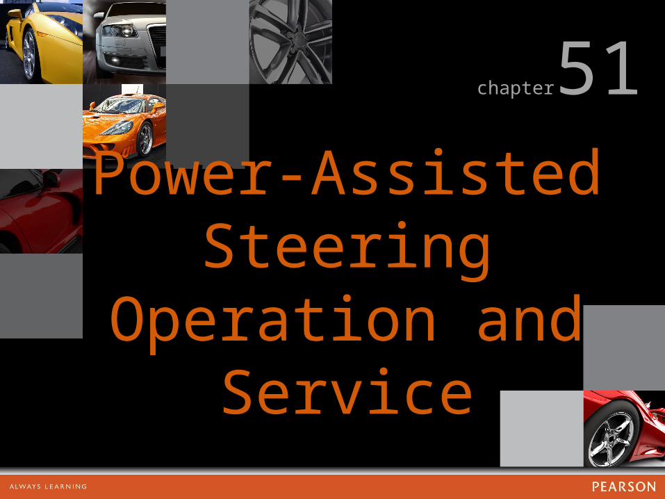
FIGURE 51.2 FIGURE 51.2 Typical remote reservoir.Typical remote reservoir.
chapter 51 Power-Assisted Steering Operation and Service
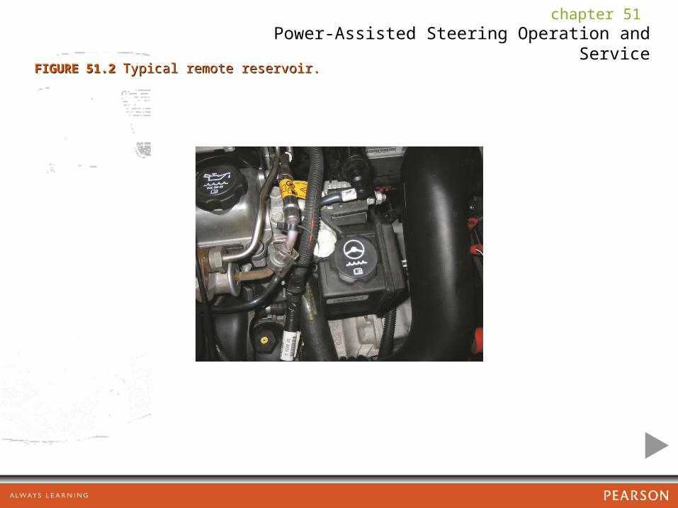
FIGURE 51.3 FIGURE 51.3 Typical power steering pump assemblies.Typical power steering pump assemblies.
chapter 51 Power-Assisted Steering Operation and Service
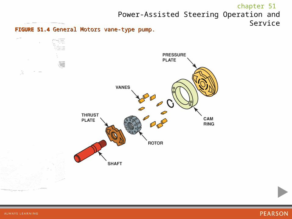
FIGURE 51.4 FIGURE 51.4 General Motors vane-type pump.General Motors vane-type pump.

chapter 51 Power-Assisted Steering Operation and Service
FIGURE 51.5 FIGURE 51.5 The power steering fluid cooler, if used, is located in the return hose. Often The power steering fluid cooler, if used, is located in the return hose. Often the “cooler” is simply a length of return metal line that is arranged in a loop and routed the “cooler” is simply a length of return metal line that is arranged in a loop and routed near the front of the vehicle. The airflow past the return line helps reduce the near the front of the vehicle. The airflow past the return line helps reduce the temperature of the fluid. temperature of the fluid.
chapter 51 Power-Assisted Steering Operation and Service
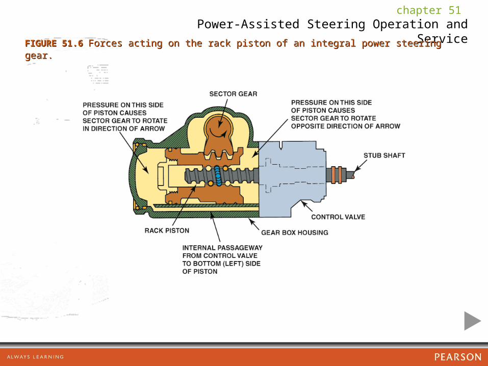
FIGURE 51.6 FIGURE 51.6 Forces acting on the rack piston of an integral power steering gear.Forces acting on the rack piston of an integral power steering gear.
chapter 51 Power-Assisted Steering Operation and Service
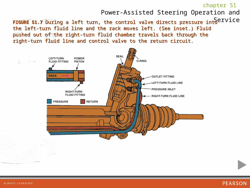
FIGURE 51.7 FIGURE 51.7 During a left turn, the control valve directs pressure into the left-turn fluid During a left turn, the control valve directs pressure into the left-turn fluid line and the rack moves left. (See inset.) Fluid pushed out of the right-turn fluid line and the rack moves left. (See inset.) Fluid pushed out of the right-turn fluid chamber travels back through the right-turn fluid line and control valve to the return chamber travels back through the right-turn fluid line and control valve to the return circuit.circuit.

chapter 51 Power-Assisted Steering Operation and Service
FIGURE 51.8 FIGURE 51.8 The control valve routes high-pressure fluid to the left-hand side of the The control valve routes high-pressure fluid to the left-hand side of the power piston, which pushes the piston and assists in moving the rack toward the right power piston, which pushes the piston and assists in moving the rack toward the right when the steering wheel is turned right.when the steering wheel is turned right.

chapter 51 Power-Assisted Steering Operation and Service
FIGURE 51.9 FIGURE 51.9 Low-speed flow control.Low-speed flow control.
chapter 51 Power-Assisted Steering Operation and Service
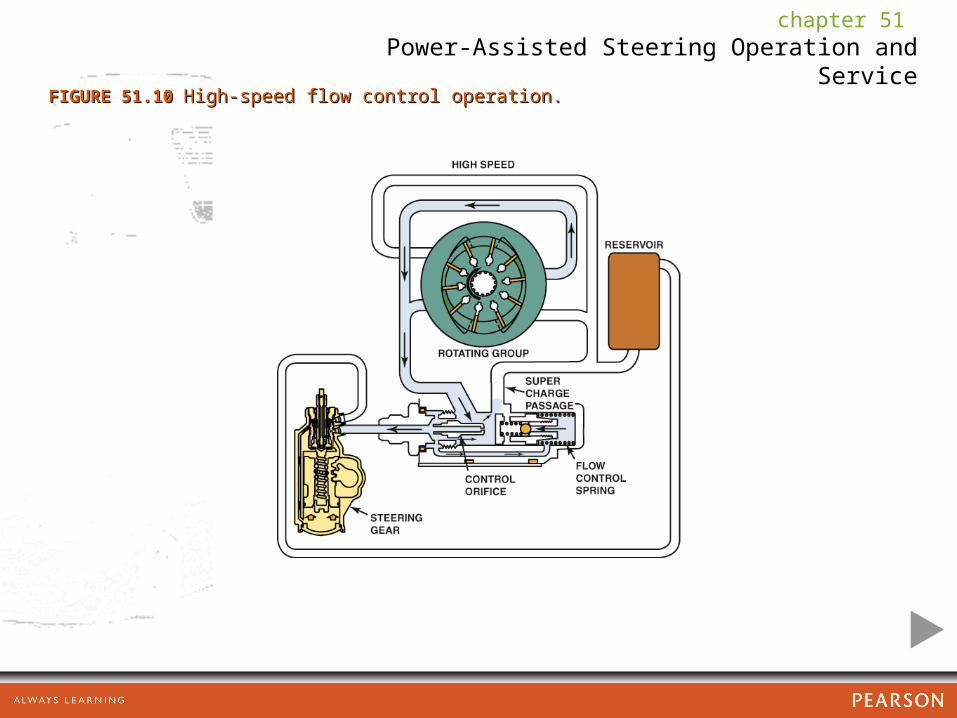
FIGURE 51.10 FIGURE 51.10 High-speed flow control operation.High-speed flow control operation.
chapter 51 Power-Assisted Steering Operation and Service
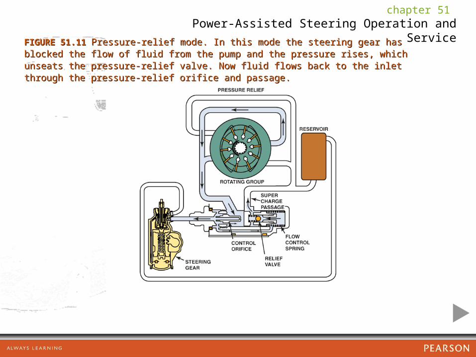
FIGURE 51.11 FIGURE 51.11 Pressure-relief mode. In this mode the steering gear has blocked the flow Pressure-relief mode. In this mode the steering gear has blocked the flow of fluid from the pump and the pressure rises, which unseats the pressure-relief valve. of fluid from the pump and the pressure rises, which unseats the pressure-relief valve. Now fluid flows back to the inlet through the pressure-relief orifice and passage. Now fluid flows back to the inlet through the pressure-relief orifice and passage.

chapter 51 Power-Assisted Steering Operation and Service
FIGURE 51.12 FIGURE 51.12 The power steering pressure switch is often attached to the steering gear The power steering pressure switch is often attached to the steering gear assembly.assembly.
chapter 51 Power-Assisted Steering Operation and Service
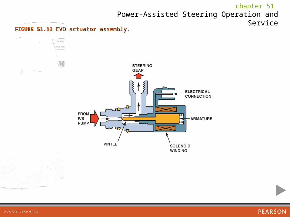
FIGURE 51.13 FIGURE 51.13 EVO actuator assembly.EVO actuator assembly.
chapter 51 Power-Assisted Steering Operation and Service
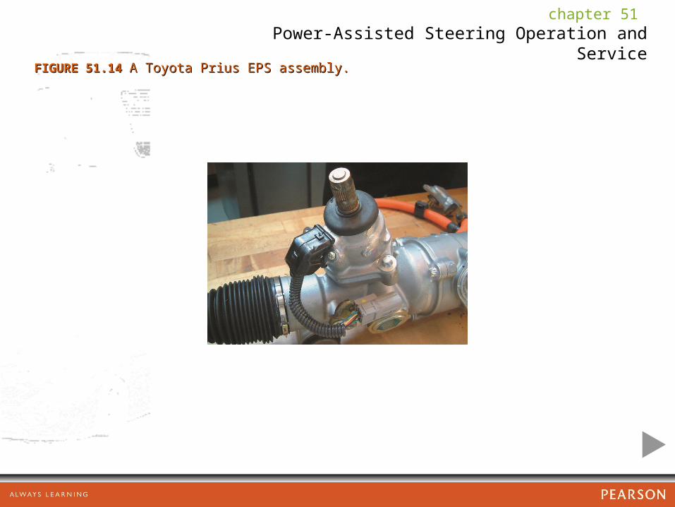
FIGURE 51.14 FIGURE 51.14 A Toyota Prius EPS assembly.A Toyota Prius EPS assembly.

chapter 51 Power-Assisted Steering Operation and Service
FIGURE 51.15 FIGURE 51.15 The torque sensor converts the torque the driver is applying to the The torque sensor converts the torque the driver is applying to the steering wheel into a voltage signal.steering wheel into a voltage signal.
chapter 51 Power-Assisted Steering Operation and Service
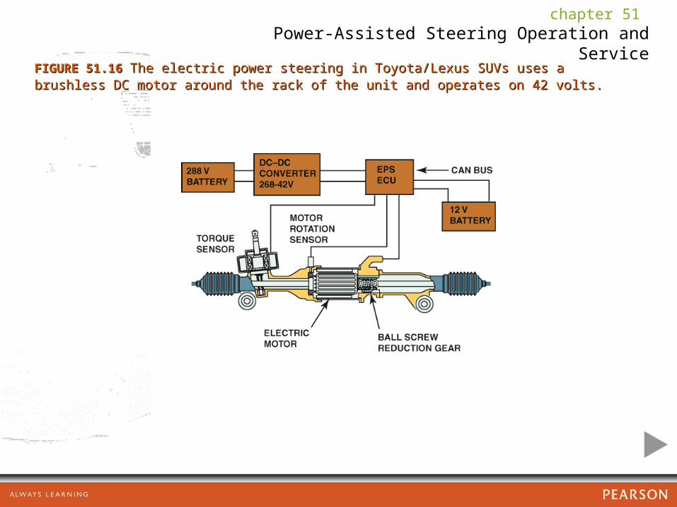
FIGURE 51.16 FIGURE 51.16 The electric power steering in Toyota/Lexus SUVs uses a brushless DC The electric power steering in Toyota/Lexus SUVs uses a brushless DC motor around the rack of the unit and operates on 42 volts.motor around the rack of the unit and operates on 42 volts.

chapter 51 Power-Assisted Steering Operation and Service
FIGURE 51.17 FIGURE 51.17 A Ford Fusion electric power steering system that uses a mini toothed belt A Ford Fusion electric power steering system that uses a mini toothed belt drive from the motor to the drive the rack.drive from the motor to the drive the rack.

chapter 51 Power-Assisted Steering Operation and Service
FIGURE 51.18 FIGURE 51.18 A cross-sectional view of a Honda electric power steering gear.A cross-sectional view of a Honda electric power steering gear.

chapter 51 Power-Assisted Steering Operation and Service
FIGURE 51.19 FIGURE 51.19 Honda electric power steering unit cutaway.Honda electric power steering unit cutaway.

chapter 51 Power-Assisted Steering Operation and Service
FIGURE 51.20 FIGURE 51.20 The power steering control module is attached to the motor of the electric The power steering control module is attached to the motor of the electric power steering assembly.power steering assembly.

chapter 51 Power-Assisted Steering Operation and Service
FIGURE 51.21 FIGURE 51.21 Schematic showing the electric power steering and the torque/position Schematic showing the electric power steering and the torque/position sensor.sensor.

chapter 51 Power-Assisted Steering Operation and Service
CHART 51.1CHART 51.1

chapter 51 Power-Assisted Steering Operation and Service
FIGURE 51.22 FIGURE 51.22 A typical service manual illustration showing the method to use to A typical service manual illustration showing the method to use to properly tension the accessory drive belt.properly tension the accessory drive belt.
chapter 51 Power-Assisted Steering Operation and Service
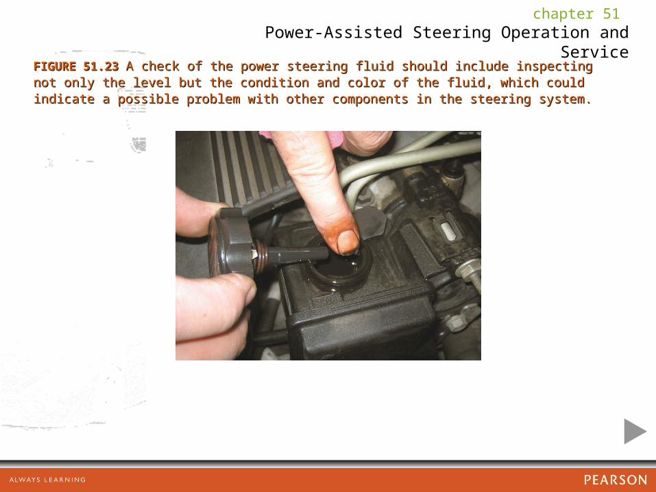
FIGURE 51.23 FIGURE 51.23 A check of the power steering fluid should include inspecting not only the A check of the power steering fluid should include inspecting not only the level but the condition and color of the fluid, which could indicate a possible problem level but the condition and color of the fluid, which could indicate a possible problem with other components in the steering system. with other components in the steering system.
chapter 51 Power-Assisted Steering Operation and Service
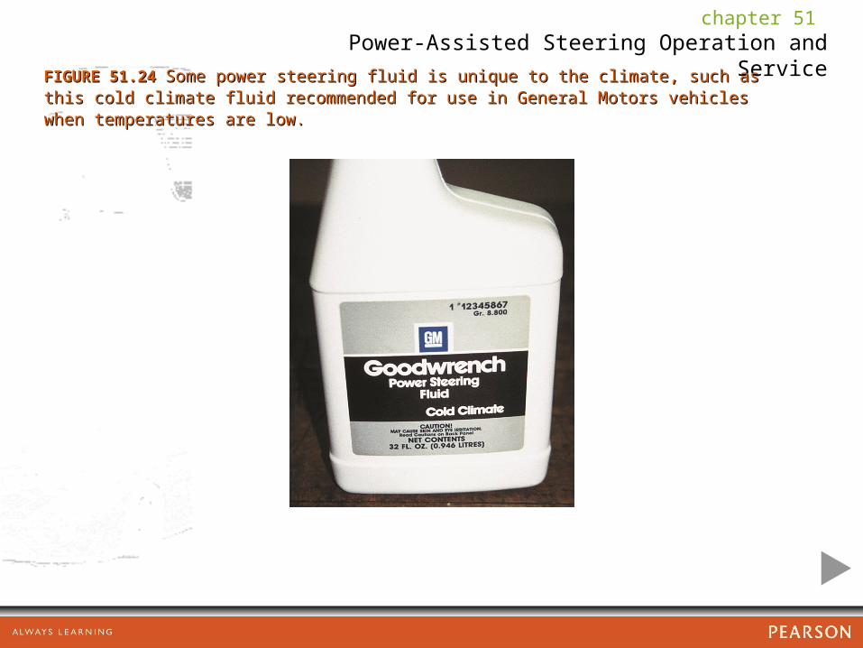
FIGURE 51.24 FIGURE 51.24 Some power steering fluid is unique to the climate, such as this cold Some power steering fluid is unique to the climate, such as this cold climate fluid recommended for use in General Motors vehicles when temperatures are climate fluid recommended for use in General Motors vehicles when temperatures are low. low.

chapter 51 Power-Assisted Steering Operation and Service
FIGURE 51.25 FIGURE 51.25 Inspect both high-pressure and return power steering hoses. Make sure Inspect both high-pressure and return power steering hoses. Make sure the hoses are routed correctly and not touching sections of the body to prevent power the hoses are routed correctly and not touching sections of the body to prevent power steering noise from being transferred to the passenger compartment. steering noise from being transferred to the passenger compartment.