Embed Size (px)
Citation preview
PS-23
POWER ASSISTED SYSTEM (POWER STEERING)STEERING GEARBOX
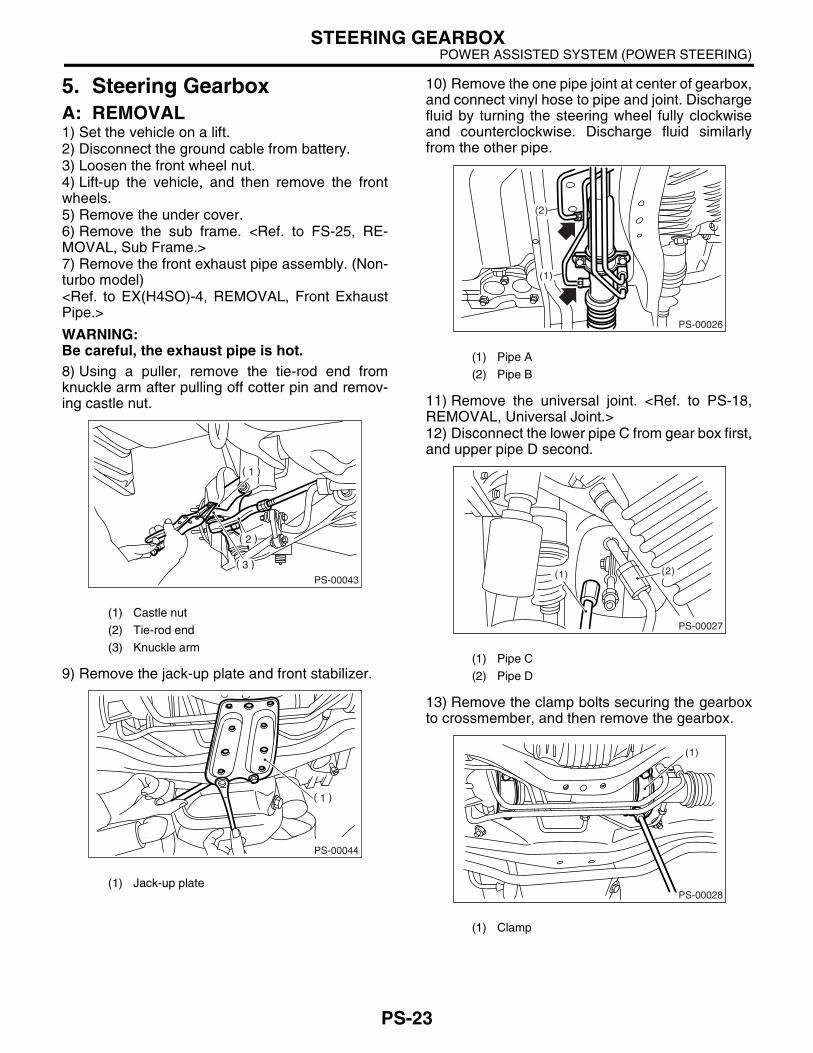
5. Steering GearboxA: REMOVAL1) Set the vehicle on a lift.2) Disconnect the ground cable from battery.3) Loosen the front wheel nut.4) Lift-up the vehicle, and then remove the frontwheels.5) Remove the under cover.6) Remove the sub frame. <Ref. to FS-25, RE-MOVAL, Sub Frame.>7) Remove the front exhaust pipe assembly. (Non-turbo model)<Ref. to EX(H4SO)-4, REMOVAL, Front ExhaustPipe.>
WARNING:Be careful, the exhaust pipe is hot.8) Using a puller, remove the tie-rod end fromknuckle arm after pulling off cotter pin and remov-ing castle nut.
9) Remove the jack-up plate and front stabilizer.
10) Remove the one pipe joint at center of gearbox,and connect vinyl hose to pipe and joint. Dischargefluid by turning the steering wheel fully clockwiseand counterclockwise. Discharge fluid similarlyfrom the other pipe.
11) Remove the universal joint. <Ref. to PS-18,REMOVAL, Universal Joint.> 12) Disconnect the lower pipe C from gear box first,and upper pipe D second.
13) Remove the clamp bolts securing the gearboxto crossmember, and then remove the gearbox.
(1) Castle nut
(2) Tie-rod end
(3) Knuckle arm
(1) Jack-up plate
PS-00043
PS-00044
(1) Pipe A
(2) Pipe B
(1) Pipe C
(2) Pipe D
(1) Clamp
(1)
(2)
PS-00026
(2)(1)
PS-00027
(1)
PS-00028

PS-24
POWER ASSISTED SYSTEM (POWER STEERING)STEERING GEARBOX
B: INSTALLATION1) Insert the gearbox into crossmember, beingcareful not to damage the gearbox boot.2) Tighten the gearbox to crossmember bracket viaclamp with bolts to specified torque.
Tightening torque:59 N·m (6.0 kgf-m, 43.4 ft-lb)
3) Connect the pipe D first to gear box, and pipe Csecond.
Tightening torque:15 N·m (1.5 kgf-m, 10.8 ft-lb)
4) Install the universal joint. <Ref. to PS-18, IN-STALLATION, Universal Joint.>5) Connect the tie-rod end and knuckle arm, andtighten with castle nut.
Castle nut tightening torque:27 N·m (2.75 kgf-m, 19.9 ft-lb)
CAUTION:When connecting, do not hit the cap at bottom of tie-rod end with hammer.
6) After tightening the castle nut to specifiedtorque, tighten it further within 60° until cotter pinhole is aligned with the slot in nut, and then bendthe cotter pin to lock.
7) Install the front stabilizer to vehicle. <Ref. to FS-23, INSTALLATION, Front Stabilizer.>8) Install the front exhaust pipe assembly.9) Install the sub frame. <Ref. to FS-25, INSTAL-LATION, Sub Frame.>10) Install the under cover. <Ref. to EI-22, INSTAL-LATION, Front Under Cover.>11) Align the center of roll connector. <Ref. to AB-18, ADJUSTMENT, Roll Connector.>12) Install the steering wheel. <Ref. to PS-17, IN-STALLATION, Steering Wheel.>13) Install the front wheels.14) Tighten the wheel nuts to specified torque.
Tightening torque:90 N·m (9.1 kgf-m, 65.8 ft-lb)
15) Connect the battery ground cable to battery.16) Pour fluid into the oil tank, and bleed air. <Ref. to PS-55, Power Steering Fluid.>17) Check for fluid leaks.18) Install the jack-up plate.19) Lower the vehicle.20) Check the fluid level in oil tank.
(1) Clamp
(1) Pipe C
(2) Pipe D
(1)
PS-00028
(2)(1)
PS-00027
(A) Cotter pin
(B) Castle nut
(C) Tie-rod end
DS-00042
(C)
(B)
(A)

PS-25
POWER ASSISTED SYSTEM (POWER STEERING)STEERING GEARBOX
21) After adjusting the toe-in and steering angle,tighten the lock nut on tie-rod end.
Tightening torque:83 N·m (8.5 kgf-m, 61.5 ft-lb)
NOTE:When adjusting the toe-in, hold boot as shown toprevent it from being rotated or twisted. If twisted,straighten it.
C: DISASSEMBLY1. RACK HOUSING ASSEMBLY1) Disconnect the four pipes from gearbox.
NOTE:Remove the pipes E and F as a single unit beingfixed at clamp plate.2) Secure the gearbox removed from vehicle invice using ST.ST 926200000 STAND
CAUTION:Secure the gearbox in a vise using ST as shown. Do not attempt to secure it without this ST.
3) Remove the tie-rod end and lock nut from gear-box.
4) Remove the small clip from boot using pliers,and then move the boot to tie-rod end side.
5) Using a flat tip screwdriver, remove the bandfrom boot.
6) Extend the rack approx. 40 mm (1.57 in) out. Un-lock the lock washer on both side of tie-rod end us-ing a flat tip screwdriver.
CAUTION:Be careful not to scratch the rack surface as oil leaks may result.
PS-00051
PS-00029
ST
(1) Clip
(1) Band
(1) Lock washer
(2) Approx. 40 mm (1.57 in)
PS-00048
(1)
PS-00082
(1)
PS-00439
(2)
(1)
PS-26
POWER ASSISTED SYSTEM (POWER STEERING)STEERING GEARBOX
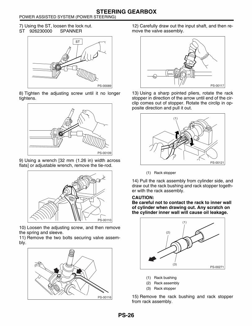
7) Using the ST, loosen the lock nut.ST 926230000 SPANNER
8) Tighten the adjusting screw until it no longertightens.
9) Using a wrench [32 mm (1.26 in) width acrossflats] or adjustable wrench, remove the tie-rod.
10) Loosen the adjusting screw, and then removethe spring and sleeve.11) Remove the two bolts securing valve assem-bly.
12) Carefully draw out the input shaft, and then re-move the valve assembly.
13) Using a sharp pointed pliers, rotate the rackstopper in direction of the arrow until end of the cir-clip comes out of stopper. Rotate the circlip in op-posite direction and pull it out.
14) Pull the rack assembly from cylinder side, anddraw out the rack bushing and rack stopper togeth-er with the rack assembly.
CAUTION:Be careful not to contact the rack to inner wall of cylinder when drawing out. Any scratch on the cylinder inner wall will cause oil leakage.
15) Remove the rack bushing and rack stopperfrom rack assembly.
PS-00089
ST
PS-00109
PS-00110
PS-00116
(1) Rack stopper
(1) Rack bushing
(2) Rack assembly
(3) Rack stopper
PS-00117
(1)
PS-00121
PS-00271
(1)
(2)
(3)

PS-27
POWER ASSISTED SYSTEM (POWER STEERING)STEERING GEARBOX
16) Remove the oil seal from rack.17) Insert the ST from pinion housing side, andthen remove the oil seal using a press.ST 34199AE050 REMOVER
2. CONTROL VALVE1) Disconnect the four pipes from gearbox.
NOTE:Remove the pipes E and F as a single unit beingfixed at clamp plate.2) Secure the gearbox removed from the vehicle invise using ST.ST 926200000 STAND
CAUTION:Secure the gearbox in a vise using ST as shown. Do not attempt to secure it without this ST.
3) Using the ST, loosen the lock nut.ST 926230000 SPANNER
4) Tighten the adjusting screw until it no longertightens.
5) Loosen the adjusting screw, and then removethe spring and sleeve.6) Remove the two bolts securing valve assembly.
7) Carefully draw out the input shaft, and then re-move the valve assembly.
(1) Press
(2) Oil seal
PS-00138
(2)
(1)
ST
PS-00029
ST
PS-00139
ST
PS-00140
PS-00116
PS-00143
PS-28
POWER ASSISTED SYSTEM (POWER STEERING)STEERING GEARBOX
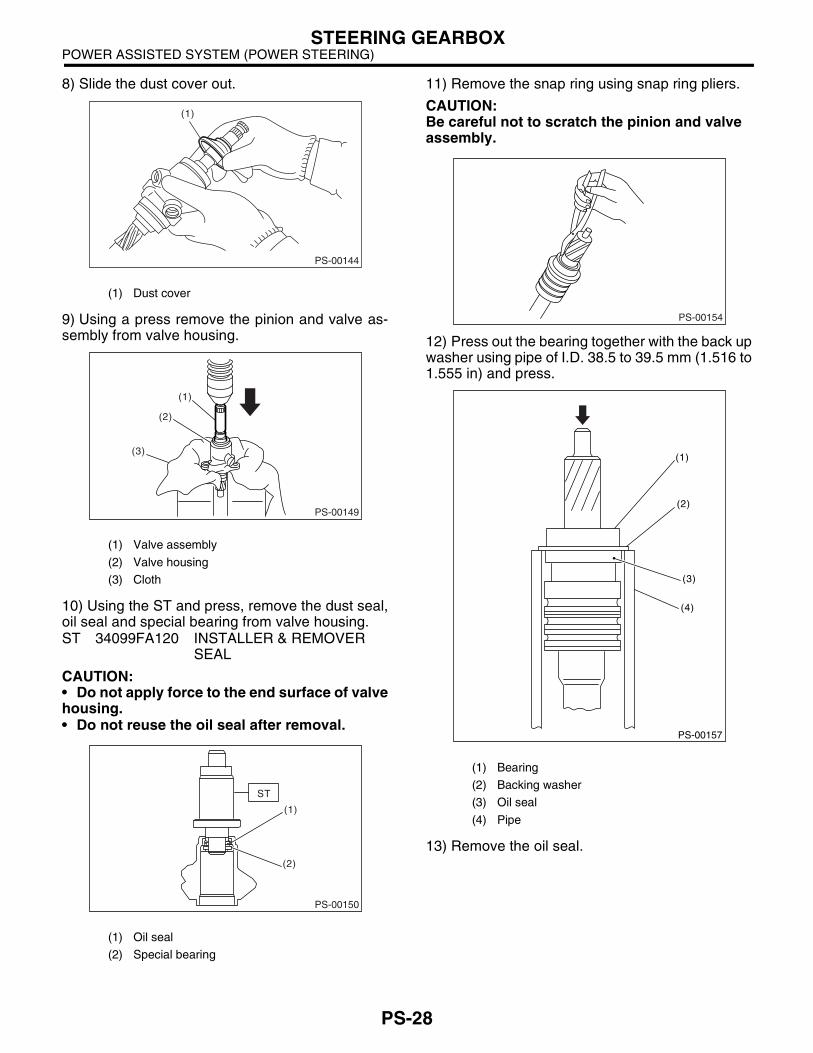
8) Slide the dust cover out.
9) Using a press remove the pinion and valve as-sembly from valve housing.
10) Using the ST and press, remove the dust seal,oil seal and special bearing from valve housing.ST 34099FA120 INSTALLER & REMOVER
SEAL
CAUTION:• Do not apply force to the end surface of valvehousing.• Do not reuse the oil seal after removal.
11) Remove the snap ring using snap ring pliers.
CAUTION:Be careful not to scratch the pinion and valve assembly.
12) Press out the bearing together with the back upwasher using pipe of I.D. 38.5 to 39.5 mm (1.516 to1.555 in) and press.
13) Remove the oil seal.
(1) Dust cover
(1) Valve assembly
(2) Valve housing
(3) Cloth
(1) Oil seal
(2) Special bearing
PS-00144
(1)
(2)
(3)
(1)
PS-00149
(2)
(1)
PS-00150
ST
(1) Bearing
(2) Backing washer
(3) Oil seal
(4) Pipe
PS-00154
PS-00157
(1)
(2)
(3)
(4)
PS-29
POWER ASSISTED SYSTEM (POWER STEERING)STEERING GEARBOX
D: ASSEMBLY1. RACK HOUSING ASSEMBLY
CAUTION:Use only SUBARU genuine grease for the gear-box.
Specified grease for gearbox:VALIANT GREASE M2 (Part No. 003608001)
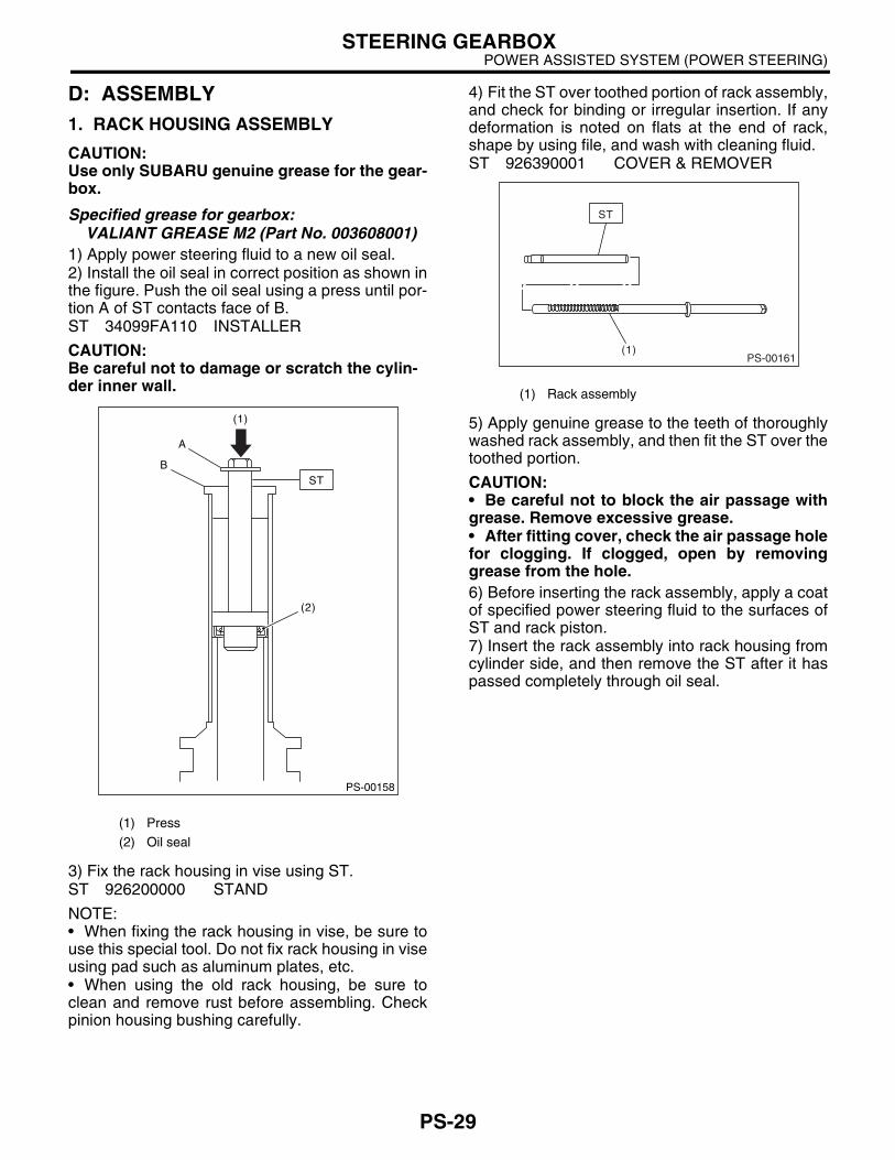
1) Apply power steering fluid to a new oil seal.2) Install the oil seal in correct position as shown inthe figure. Push the oil seal using a press until por-tion A of ST contacts face of B.ST 34099FA110 INSTALLER
CAUTION:Be careful not to damage or scratch the cylin-der inner wall.
3) Fix the rack housing in vise using ST.ST 926200000 STAND
NOTE:• When fixing the rack housing in vise, be sure touse this special tool. Do not fix rack housing in viseusing pad such as aluminum plates, etc.• When using the old rack housing, be sure toclean and remove rust before assembling. Checkpinion housing bushing carefully.
4) Fit the ST over toothed portion of rack assembly,and check for binding or irregular insertion. If anydeformation is noted on flats at the end of rack,shape by using file, and wash with cleaning fluid.ST 926390001 COVER & REMOVER
5) Apply genuine grease to the teeth of thoroughlywashed rack assembly, and then fit the ST over thetoothed portion.
CAUTION:• Be careful not to block the air passage withgrease. Remove excessive grease.• After fitting cover, check the air passage holefor clogging. If clogged, open by removinggrease from the hole.6) Before inserting the rack assembly, apply a coatof specified power steering fluid to the surfaces ofST and rack piston.7) Insert the rack assembly into rack housing fromcylinder side, and then remove the ST after it haspassed completely through oil seal.
(1) Press
(2) Oil seal
PS-00158
(1)
(2)
A
BST
(1) Rack assembly
(1)PS-00161
ST
PS-30
POWER ASSISTED SYSTEM (POWER STEERING)STEERING GEARBOX
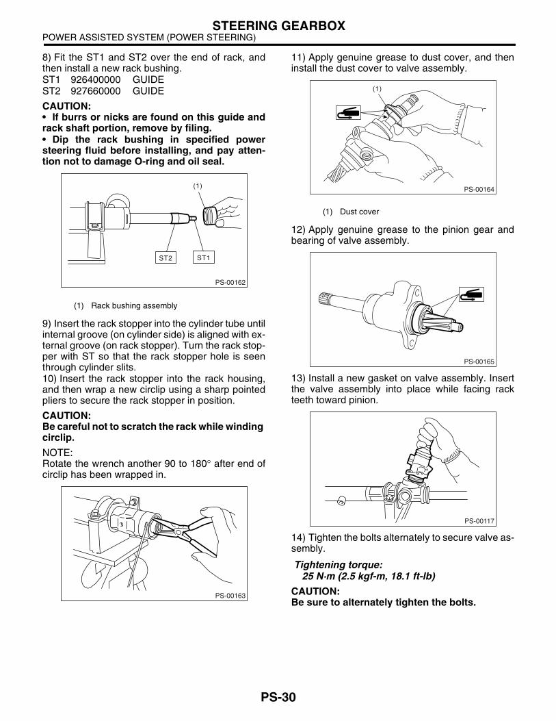
8) Fit the ST1 and ST2 over the end of rack, andthen install a new rack bushing.ST1 926400000 GUIDEST2 927660000 GUIDE
CAUTION:• If burrs or nicks are found on this guide andrack shaft portion, remove by filing.• Dip the rack bushing in specified powersteering fluid before installing, and pay atten-tion not to damage O-ring and oil seal.
9) Insert the rack stopper into the cylinder tube untilinternal groove (on cylinder side) is aligned with ex-ternal groove (on rack stopper). Turn the rack stop-per with ST so that the rack stopper hole is seenthrough cylinder slits.10) Insert the rack stopper into the rack housing,and then wrap a new circlip using a sharp pointedpliers to secure the rack stopper in position.
CAUTION:Be careful not to scratch the rack while winding circlip.
NOTE:Rotate the wrench another 90 to 180° after end ofcirclip has been wrapped in.
11) Apply genuine grease to dust cover, and theninstall the dust cover to valve assembly.
12) Apply genuine grease to the pinion gear andbearing of valve assembly.
13) Install a new gasket on valve assembly. Insertthe valve assembly into place while facing rackteeth toward pinion.
14) Tighten the bolts alternately to secure valve as-sembly.
Tightening torque:25 N·m (2.5 kgf-m, 18.1 ft-lb)
CAUTION:Be sure to alternately tighten the bolts.
(1) Rack bushing assembly
(1)
PS-00162
ST1ST2
PS-00163
(1) Dust cover
PS-00164
(1)
PS-00165
PS-00117

PS-31
POWER ASSISTED SYSTEM (POWER STEERING)STEERING GEARBOX
15) Temporarily install the rack, and then operate itfrom lock to lock two or three times to make it fit in.Remove the grease blocking air vent hole.
CAUTION:If operating the rack from lock to lock without installing tie-rod, it may damage the oil seal. Al-ways install the tie-rods LH and RH.16) Apply a coat of grease to the sliding surface ofsleeve and seating surface of spring, and then in-sert sleeve into steering body.Charge the adjusting screw with grease, and theninsert the spring into adjusting screw and install onsteering body.
17) Tighten the adjusting screw to specified torque.
Tightening torque:7.4 N·m (0.75 kgf-m, 5.4 ft-lb)
18) After tightening to the specified tighteningtorque, loosen it by 25°.19) Remove the tie-rod.20) Verify that play is within specified value. <Ref.to PS-38, SERVICE LIMIT, INSPECTION, SteeringGearbox.>
21) Loosen the adjusting screw, and then apply liq-uid gasket to at least 1/3 of the entire perimeter ofadjusting screw thread.
Liquid gasket:THREE BOND 1141
22) Tighten the adjusting screw to specified torque.
Tightening torque:7.4 N·m (0.75 kgf-m, 5.4 ft-lb)
23) After tightening to the specified tighteningtorque, loosen it by 25°.24) Install the lock nut. While holding the adjustingscrew with a wrench, tighten lock nut using ST.ST 926230000 SPANNER
Tightening torque (Lock nut):39 N·m (4.0 kgf-m, 28.9 ft-lb)
NOTE:Hold the adjusting screw with a wrench to prevent itfrom turning while tightening lock nut.25) Extend the rack approx. 40 mm (1.57 in) be-yond side of steering body.26) Install the tie-rod and a new lock washer intorack.
Tightening torque:78 N·m (8.0 kgf-m, 57.9 ft-lb)
(1) Sleeve
(2) Spring
(3) Adjusting screw
PS-00167
(2)
(1)
(3)
(1) Apply liquid gasket to at least 1/3 of entire perimeter.
(1) Lock washer
(2) Approx. 40 mm (1.57 in)
PS-00092
PS-00439
(2)
(1)
PS-32
POWER ASSISTED SYSTEM (POWER STEERING)STEERING GEARBOX
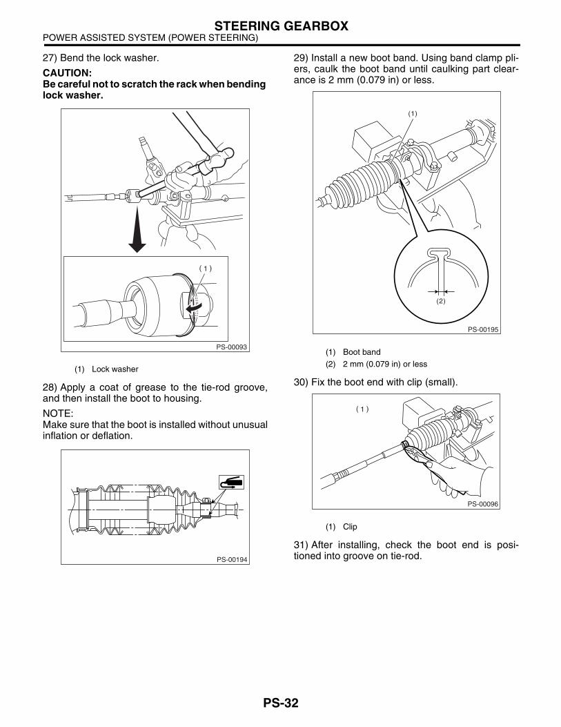
27) Bend the lock washer.
CAUTION:Be careful not to scratch the rack when bending lock washer.
28) Apply a coat of grease to the tie-rod groove,and then install the boot to housing.
NOTE:Make sure that the boot is installed without unusualinflation or deflation.
29) Install a new boot band. Using band clamp pli-ers, caulk the boot band until caulking part clear-ance is 2 mm (0.079 in) or less.
30) Fix the boot end with clip (small).
31) After installing, check the boot end is posi-tioned into groove on tie-rod.
(1) Lock washer
PS-00093
PS-00194
(1) Boot band
(2) 2 mm (0.079 in) or less
(1) Clip
PS-00195
(1)
(2)
PS-00096
PS-33
POWER ASSISTED SYSTEM (POWER STEERING)STEERING GEARBOX
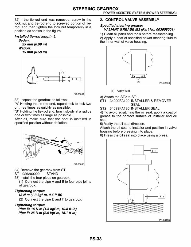
32) If the tie-rod end was removed, screw in thelock nut and tie-rod end to screwed portion of tie-rod, and then tighten the lock nut temporarily in aposition as shown in the figure.
Installed tie-rod length: LSedan:
25 mm (0.98 in)Wagon:
15 mm (0.59 in)
33) Inspect the gearbox as follows:“A” Holding the tie-rod end, repeat lock to lock twoor three times as quickly as possible.“B” Holding the tie-rod end, turn it slowly at a radiusone or two times as large as possible.After all, make sure that the boot is installed inspecified position without deflation.
34) Remove the gearbox from ST.ST 926200000 STAND35) Install the four pipes on gearbox.
(1) Connect the pipe A and B to four pipe jointsof gearbox.
Tightening torque:13 N·m (1.3 kgf-m, 9.4 ft-lb)(2) Connect the pipe E and F to gearbox.
Tightening torque:Pipe E: 15 N·m (1.5 kgf-m, 10.8 ft-lb)Pipe F: 25 N·m (2.5 kgf-m, 18.1 ft-lb)
2. CONTROL VALVE ASSEMBLY
Specified steering grease:VALIANT GREASE M2 (Part No. 003608001)
1) Clean all parts and tools before reassembling.2) Apply a coat of specified power steering fluid tothe inner wall of valve housing.
3) Attach the ST2 to ST1.ST1 34099FA120 INSTALLER & REMOVER
SEALST2 34099FA130 INSTALLER SEAL4) To avoid scratching the oil seal, apply a coat ofgrease to the contact surface of installer and oilseal.5) Verify the oil seal direction.Attach the oil seal to installer and position in valvehousing before pressing into place.6) Press the oil seal into place using a press.
PS-00097
L
PS-00098
BA
(1) Apply fluid.
PS-00169(1)
PS-00170
ST1
ST2
PS-34
POWER ASSISTED SYSTEM (POWER STEERING)STEERING GEARBOX
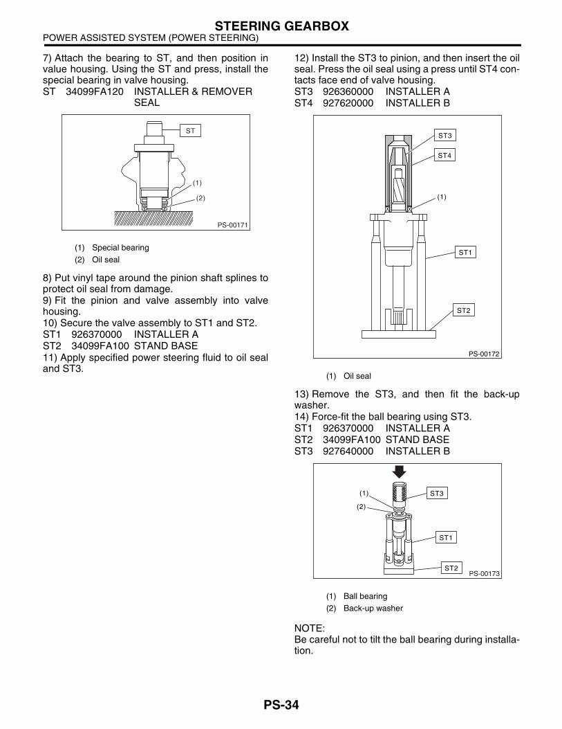
7) Attach the bearing to ST, and then position invalue housing. Using the ST and press, install thespecial bearing in valve housing.ST 34099FA120 INSTALLER & REMOVER
SEAL
8) Put vinyl tape around the pinion shaft splines toprotect oil seal from damage.9) Fit the pinion and valve assembly into valvehousing.10) Secure the valve assembly to ST1 and ST2.ST1 926370000 INSTALLER AST2 34099FA100 STAND BASE11) Apply specified power steering fluid to oil sealand ST3.
12) Install the ST3 to pinion, and then insert the oilseal. Press the oil seal using a press until ST4 con-tacts face end of valve housing.ST3 926360000 INSTALLER AST4 927620000 INSTALLER B
13) Remove the ST3, and then fit the back-upwasher.14) Force-fit the ball bearing using ST3.ST1 926370000 INSTALLER AST2 34099FA100 STAND BASEST3 927640000 INSTALLER B
NOTE:Be careful not to tilt the ball bearing during installa-tion.
(1) Special bearing
(2) Oil seal
(2)
(1)
PS-00171
ST
(1) Oil seal
(1) Ball bearing
(2) Back-up washer
PS-00172
ST1
ST4
(1)
ST2
ST3
PS-00173
ST1
ST2
ST3 (1)
(2)
PS-35
POWER ASSISTED SYSTEM (POWER STEERING)STEERING GEARBOX
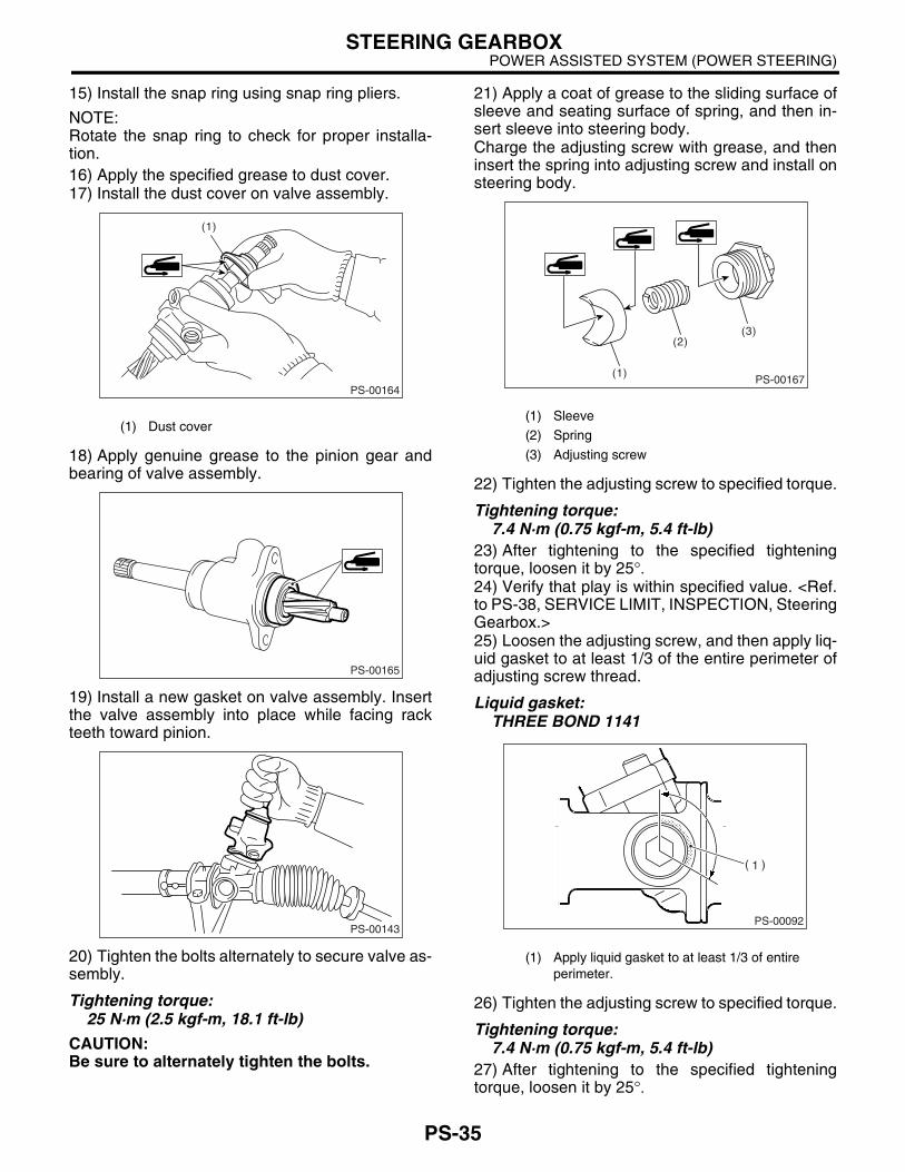
15) Install the snap ring using snap ring pliers.
NOTE:Rotate the snap ring to check for proper installa-tion.16) Apply the specified grease to dust cover.17) Install the dust cover on valve assembly.
18) Apply genuine grease to the pinion gear andbearing of valve assembly.
19) Install a new gasket on valve assembly. Insertthe valve assembly into place while facing rackteeth toward pinion.
20) Tighten the bolts alternately to secure valve as-sembly.
Tightening torque:25 N·m (2.5 kgf-m, 18.1 ft-lb)
CAUTION:Be sure to alternately tighten the bolts.
21) Apply a coat of grease to the sliding surface ofsleeve and seating surface of spring, and then in-sert sleeve into steering body.Charge the adjusting screw with grease, and theninsert the spring into adjusting screw and install onsteering body.
22) Tighten the adjusting screw to specified torque.
Tightening torque:7.4 N·m (0.75 kgf-m, 5.4 ft-lb)
23) After tightening to the specified tighteningtorque, loosen it by 25°.24) Verify that play is within specified value. <Ref.to PS-38, SERVICE LIMIT, INSPECTION, SteeringGearbox.>25) Loosen the adjusting screw, and then apply liq-uid gasket to at least 1/3 of the entire perimeter ofadjusting screw thread.
Liquid gasket:THREE BOND 1141
26) Tighten the adjusting screw to specified torque.
Tightening torque:7.4 N·m (0.75 kgf-m, 5.4 ft-lb)
27) After tightening to the specified tighteningtorque, loosen it by 25°.
(1) Dust cover
PS-00164
(1)
PS-00165
PS-00143
(1) Sleeve
(2) Spring
(3) Adjusting screw
(1) Apply liquid gasket to at least 1/3 of entire perimeter.
PS-00167
(2)
(1)
(3)
PS-00092
PS-36
POWER ASSISTED SYSTEM (POWER STEERING)STEERING GEARBOX
28) Install the lock nut. While holding the adjustingscrew with a wrench, tighten lock nut using ST.ST 926230000 SPANNER
Tightening torque (Lock nut):39 N·m (4.0 kgf-m, 28.9 ft-lb)
NOTE:Hold the adjusting screw with a wrench to prevent itfrom turning while tightening lock nut.29) Remove the gearbox from ST.30) Install the four pipes on gearbox.
(1) Connect the pipe A and B to the gearbox.
Tightening torque:13 N·m (1.3 kgf-m, 9.4 ft-lb)(2) Connect the pipe E and F to gearbox.
Tightening torque:Pipe E: 15 N·m (1.5 kgf-m, 10.8 ft-lb)Pipe F: 25 N·m (2.5 kgf-m, 18.1 ft-lb)
PS-37
POWER ASSISTED SYSTEM (POWER STEERING)STEERING GEARBOX
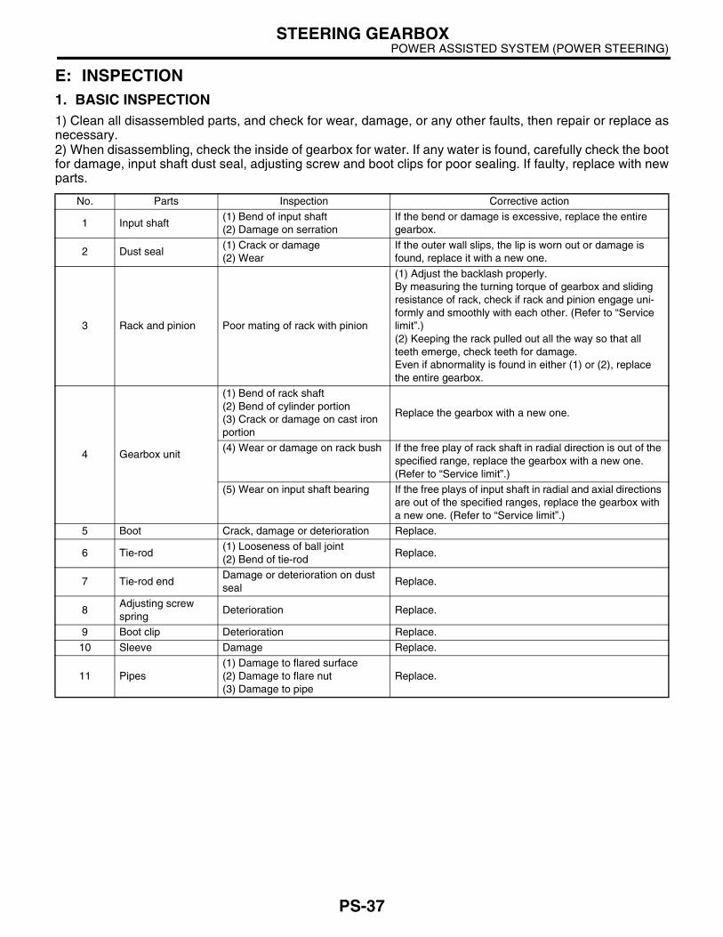
E: INSPECTION1. BASIC INSPECTION1) Clean all disassembled parts, and check for wear, damage, or any other faults, then repair or replace asnecessary.2) When disassembling, check the inside of gearbox for water. If any water is found, carefully check the bootfor damage, input shaft dust seal, adjusting screw and boot clips for poor sealing. If faulty, replace with newparts.
No. Parts Inspection Corrective action
1 Input shaft(1) Bend of input shaft(2) Damage on serration
If the bend or damage is excessive, replace the entire gearbox.
2 Dust seal(1) Crack or damage(2) Wear
If the outer wall slips, the lip is worn out or damage is found, replace it with a new one.
3 Rack and pinion Poor mating of rack with pinion
(1) Adjust the backlash properly. By measuring the turning torque of gearbox and sliding resistance of rack, check if rack and pinion engage uni-formly and smoothly with each other. (Refer to “Service limit”.)(2) Keeping the rack pulled out all the way so that all teeth emerge, check teeth for damage. Even if abnormality is found in either (1) or (2), replace the entire gearbox.
4 Gearbox unit
(1) Bend of rack shaft(2) Bend of cylinder portion(3) Crack or damage on cast iron portion
Replace the gearbox with a new one.
(4) Wear or damage on rack bush If the free play of rack shaft in radial direction is out of the specified range, replace the gearbox with a new one. (Refer to “Service limit”.)
(5) Wear on input shaft bearing If the free plays of input shaft in radial and axial directions are out of the specified ranges, replace the gearbox with a new one. (Refer to “Service limit”.)
5 Boot Crack, damage or deterioration Replace.
6 Tie-rod(1) Looseness of ball joint(2) Bend of tie-rod
Replace.
7 Tie-rod endDamage or deterioration on dust seal
Replace.
8Adjusting screw spring
Deterioration Replace.
9 Boot clip Deterioration Replace.
10 Sleeve Damage Replace.
11 Pipes(1) Damage to flared surface(2) Damage to flare nut(3) Damage to pipe
Replace.
PS-38
POWER ASSISTED SYSTEM (POWER STEERING)STEERING GEARBOX
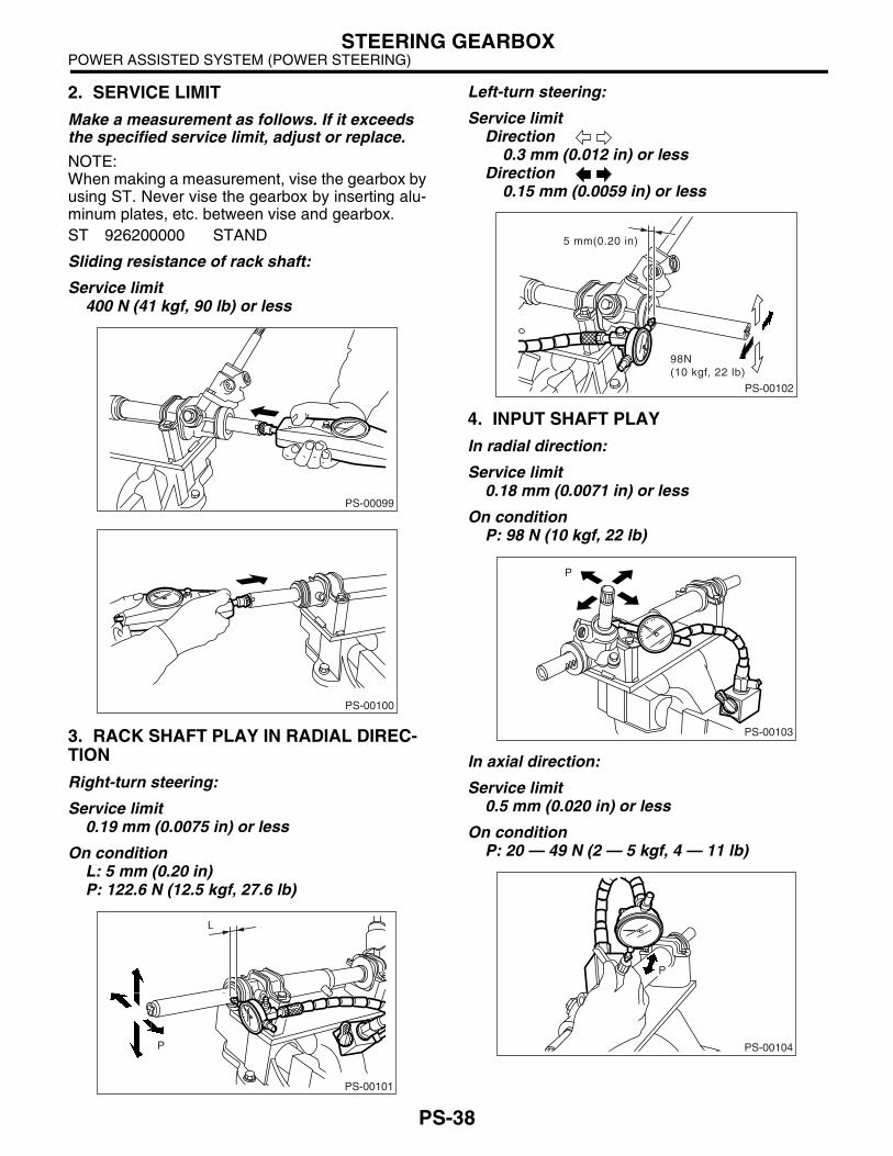
2. SERVICE LIMIT
Make a measurement as follows. If it exceeds the specified service limit, adjust or replace.
NOTE:When making a measurement, vise the gearbox byusing ST. Never vise the gearbox by inserting alu-minum plates, etc. between vise and gearbox.ST 926200000 STAND
Sliding resistance of rack shaft:
Service limit400 N (41 kgf, 90 lb) or less
3. RACK SHAFT PLAY IN RADIAL DIREC-TION
Right-turn steering:
Service limit0.19 mm (0.0075 in) or less
On conditionL: 5 mm (0.20 in)P: 122.6 N (12.5 kgf, 27.6 lb)
Left-turn steering:
Service limitDirection
0.3 mm (0.012 in) or lessDirection
0.15 mm (0.0059 in) or less
4. INPUT SHAFT PLAY
In radial direction:
Service limit0.18 mm (0.0071 in) or less
On conditionP: 98 N (10 kgf, 22 lb)
In axial direction:
Service limit0.5 mm (0.020 in) or less
On conditionP: 20 — 49 N (2 — 5 kgf, 4 — 11 lb)
PS-00099
PS-00100
PS-00101
P
L
PS-00102
5 mm(0.20 in)
98N(10 kgf, 22 lb)
PS-00103
P
PS-00104
P
PS-39
POWER ASSISTED SYSTEM (POWER STEERING)STEERING GEARBOX
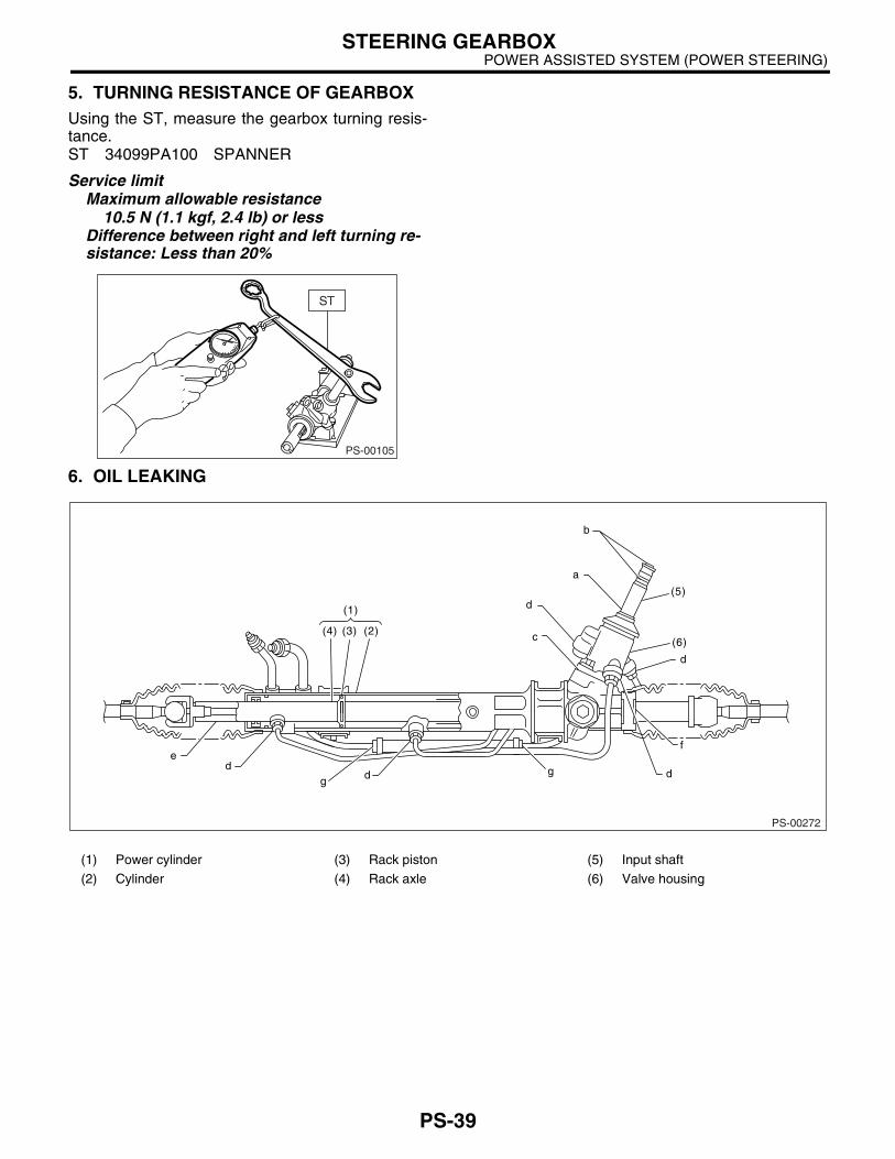
5. TURNING RESISTANCE OF GEARBOXUsing the ST, measure the gearbox turning resis-tance.ST 34099PA100 SPANNER
Service limitMaximum allowable resistance
10.5 N (1.1 kgf, 2.4 lb) or lessDifference between right and left turning re-sistance: Less than 20%
6. OIL LEAKING
PS-00105
(1) Power cylinder (3) Rack piston (5) Input shaft
(2) Cylinder (4) Rack axle (6) Valve housing
PS-00272
(4) (3) (2)
(5)
(6)c
d
d
a
b
(1)
de
d
f
gdg

PS-40
POWER ASSISTED SYSTEM (POWER STEERING)STEERING GEARBOX
1) Lift up the vehicle.2) Even if the location of the leak can be easilyfound by observing the leaking condition, it is nec-essary to thoroughly remove the fluid from the sus-pected portion and turn the steering wheel fromlock to lock about thirty to forty times with enginerunning, then make comparison of the suspectedportion between immediately after and severalhours after this operation.3) Inspect leakage from “a”.The oil seal is damaged. Replace the valve assem-bly with a new one.4) Inspect leakage from “b”.The torsion bar O-ring is damaged. Replace thevalve assembly with a new one.5) Inspect leakage from “c”.The oil seal is damaged. Replace the valve assem-bly or oil seal with a new one.6) Inspect leakage from “d”.The pipe is damaged. Replace the faulty pipe or O-ring.7) Inspect leakage from “g”.The hose is damaged. Replace the hose with anew one.8) If leak is other than a, b, c, d, or g, and if oil isleaking from the gearbox, move the right and leftboots toward tie-rod end side, respectively, with thegearbox mounted to the vehicle, and remove fluidfrom the surrounding portions. Then, turn the steer-ing wheel from lock to lock thirty to forty times withthe engine running, then make comparison of theleaked portion immediately after and several hoursafter this operation.
(1) Leakage from “e”The cylinder seal is damaged. Replace the rackbush with a new one.(2) Leakage from “f”There are two possible causes. Take the follow-ing step first. Remove the pipe assembly B fromthe valve housing, and close the circuit with ST.
ST 926420000 PLUGTurn the steering wheel from lock to lock thirty toforty times with the engine running, then makecomparison of the leaked portion between im-mediately after and several hours after this op-eration.
• If leakage from “f” is noted again: The oil seal of pinion and valve assembly is dam-aged. Replace the pinion and valve assembly witha new one. Or replace the oil seal and parts that aredamaged during disassembly with new ones.• If oil stops leaking from “f”: The oil seal of rack housing is damaged. Replacethe oil seal and the parts that are damaged duringdisassembly with new ones.
F: ADJUSTMENT1) Adjust the front toe. <Ref. to FS-10, FRONTWHEEL TOE-IN, INSPECTION, Wheel Align-ment.>
Standard of front toe:IN 3 — OUT 3 mm (IN 0.12 — OUT 0.12 in)
2) Adjust the steering angle of wheels.
Standard of steering angle:
3) If the steering wheel spokes are not horizontalwhen wheels are set in the straight ahead position,and error is more than 5° on the periphery of steer-ing wheel, correctly re-install the steering wheel.
4) If the steering wheel spokes are not horizontalwith vehicle set in the straight ahead position afterthis adjustment, correct it by turning the right andleft tie-rods in opposite direction by same angle.
(1) Lock nut
ModelTURBO, SEDAN and OUTBACK
Others
Inner wheel 34.5°±°±°±°±1.5°°°° 37.3°±°±°±°±1.5°°°°Outer wheel 30.3°±°±°±°±1.5°°°° 32.4°±°±°±°±1.5°°°°
PS-00107
PS-00108
0 - 17 mm(0 - 0.67 in)