Embed Size (px)
Citation preview
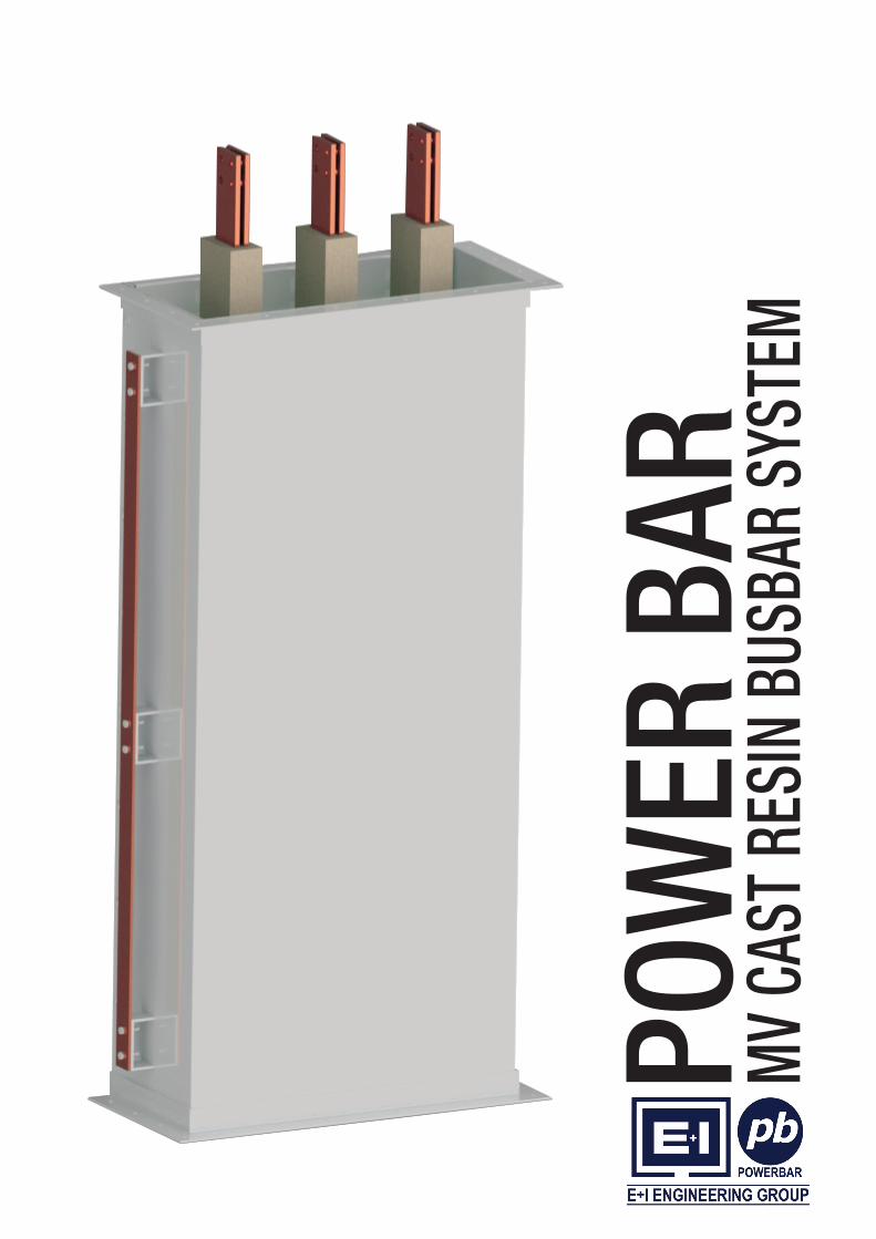
PO
WE
R B
AR
MV
CAST
RES
IN B
USBA
R SY
STEM

www.powerbarsystems.com
Powerbar HPB CAST RESINPowerbar MVCRB
CONTENTS
Introduction
Standards
Technical Features
Housing Details
Straight Lengths
Edgewise Elbows
Flatwise Elbows
Offset Sections
Combinations and Wall Crossing
Flanges and Adapter Box
Combination Flanges
Straight Joint Assembly
Support Structure Type A, B, C and D
Technical Data
01
02
03
04
05
06
07
08
09
10
11
12
13
14
01
www.powerbarsystems.com
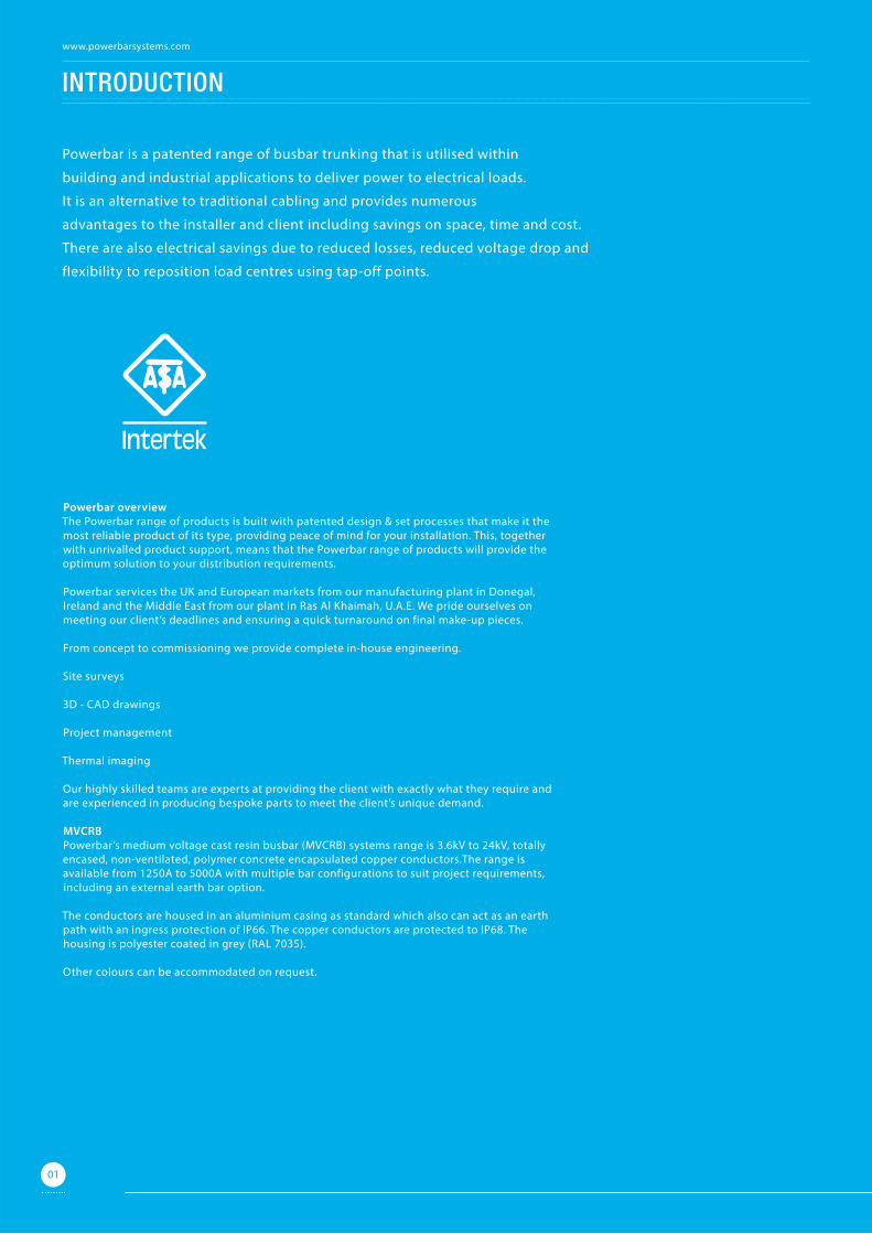
Powerbar is a patented range of busbar trunking that is utilised within
building and industrial applications to deliver power to electrical loads.
It is an alternative to traditional cabling and provides numerous
advantages to the installer and client including savings on space, time and cost.
There are also electrical savings due to reduced losses, reduced voltage drop and
flexibility to reposition load centres using tap-off points.
Powerbar overviewThe Powerbar range of products is built with patented design & set processes that make it the most reliable product of its type, providing peace of mind for your installation. This, together with unrivalled product support, means that the Powerbar range of products will provide the optimum solution to your distribution requirements.
Powerbar services the UK and European markets from our manufacturing plant in Donegal, Ireland and the Middle East from our plant in Ras Al Khaimah, U.A.E. We pride ourselves on meeting our client’s deadlines and ensuring a quick turnaround on final make-up pieces.
From concept to commissioning we provide complete in-house engineering.
Site surveys
3D - CAD drawings
Project management
Thermal imaging
Our highly skilled teams are experts at providing the client with exactly what they require and are experienced in producing bespoke parts to meet the client’s unique demand.
MVCRBPowerbar’s medium voltage cast resin busbar (MVCRB) systems range is 3.6kV to 24kV, totally encased, non-ventilated, polymer concrete encapsulated copper conductors.The range is available from 1250A to 5000A with multiple bar configurations to suit project requirements, including an external earth bar option.
The conductors are housed in an aluminium casing as standard which also can act as an earth path with an ingress protection of IP66. The copper conductors are protected to IP68. The housing is polyester coated in grey (RAL 7035).
Other colours can be accommodated on request.
INTRODUCTION
01
www.powerbarsystems.com
02
MVCRB advantages• Available according to international standards• Wide range from 1250A-5000A, 3.6kV-24kV • Outdoor installation IP68 conductor protection with IP66 aluminium
enclosure or optional (stainless steel)• High short circuit withstand capacity• Fully insulated with polymer concrete• Electro erosion resistance• Electromagnetic compatibility• Low voltage drop• Tailor made terminal elements• High mechanical strength• Fire, air, moisture, gas and watertight wall bushing• Compact design• Chemical resistance • UV resistance • Self extinguishing insulation (cast resin)• Ease of Installation • Maintenance free
StandardsThe MVCRB range is fully ASTA tested and certified. It is manufactured in a certified management system environment where quality ISO 9001-2008, safety OHSAS 18001-2007 and environmental IS0 14001-2004 standards are applied to all aspects of the manufacturing and installation processes.
It is manufactured in accordance with IEC 62271-200.
Type test• Short time current withstand test (6.6)• Temperature rise test (6.5.6)• Impulse voltage withstand test (6.2.6.2)• IP test (5.4.1.3)
Routine tests • Verification of dimensions.• Dimensional check of termination assembly.• Dry power frequency voltage withstand test• Insulation resistance test• Continuity of auxiliary wiring• Coating thickness measurement• Polyester coating adhesion test• Shade matching• Welding (NDT) test • Radiography test• Dye penetration test
ASTA certificatesPowerbar has completed extensive testing at ASTA accredited laboratories to ensure the product is certified in accordance with international standards.
Additional test• Fire resistance• ATEX (Explosive Atmosphere)• Fire barrier ISO 830
All certificates available on request
OHSAS 18001:2007OHS 533652
ISO 9001:2008FM 12680
ISO 14001:2004 No: EMS 566536
STANDARDS
Powerbar MVCRB
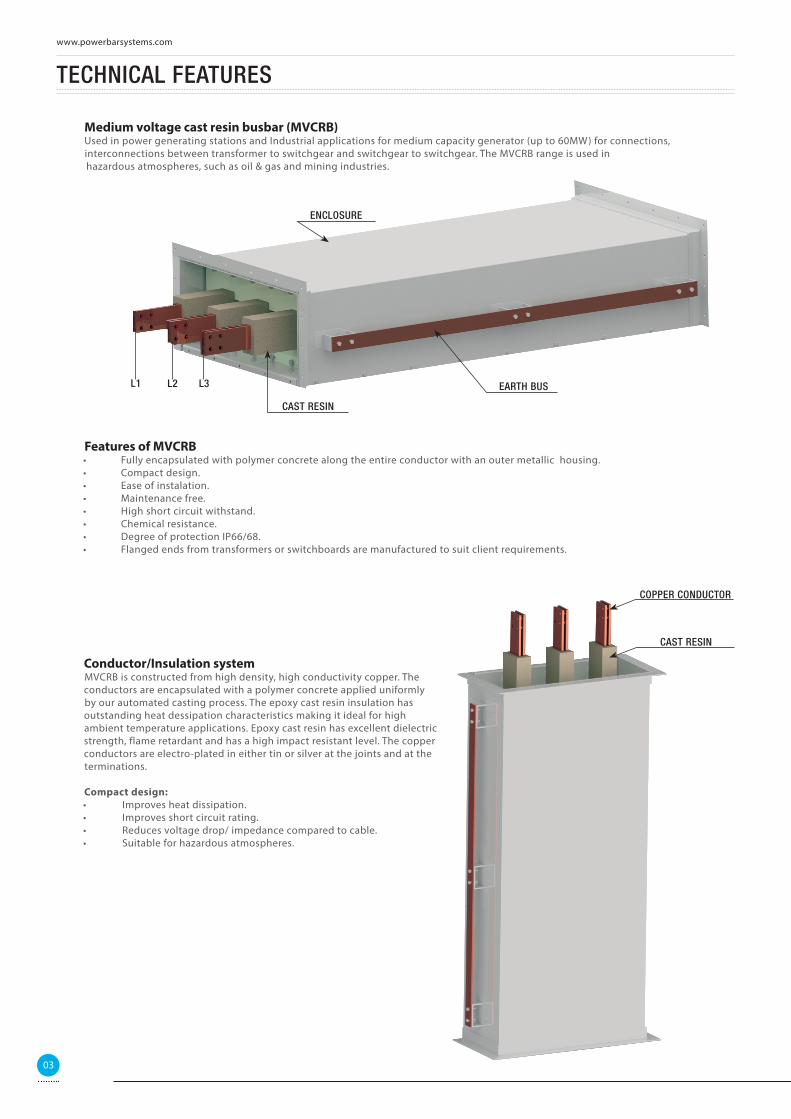
Medium voltage cast resin busbar (MVCRB)Used in power generating stations and Industrial applications for medium capacity generator (up to 60MW) for connections, interconnections between transformer to switchgear and switchgear to switchgear. The MVCRB range is used in hazardous atmospheres, such as oil & gas and mining industries.
Features of MVCRB• Fully encapsulated with polymer concrete along the entire conductor with an outer metallic housing.• Compact design.• Ease of instalation.• Maintenance free.• High short circuit withstand.• Chemical resistance.• Degree of protection IP66/68.• Flanged ends from transformers or switchboards are manufactured to suit client requirements.
TECHNICAL FEATURES
CAST RESIN
ENCLOSURE
L1 L2 L3 EARTH BUS
Conductor/Insulation systemMVCRB is constructed from high density, high conductivity copper. The conductors are encapsulated with a polymer concrete applied uniformly by our automated casting process. The epoxy cast resin insulation has outstanding heat dessipation characteristics making it ideal for high ambient temperature applications. Epoxy cast resin has excellent dielectric strength, flame retardant and has a high impact resistant level. The copper conductors are electro-plated in either tin or silver at the joints and at the terminations.
Compact design:• Improves heat dissipation. • Improves short circuit rating. • Reduces voltage drop/ impedance compared to cable. • Suitable for hazardous atmospheres.
CAST RESIN
COPPER CONDUCTOR
03
www.powerbarsystems.com
HOUSING DETAILS
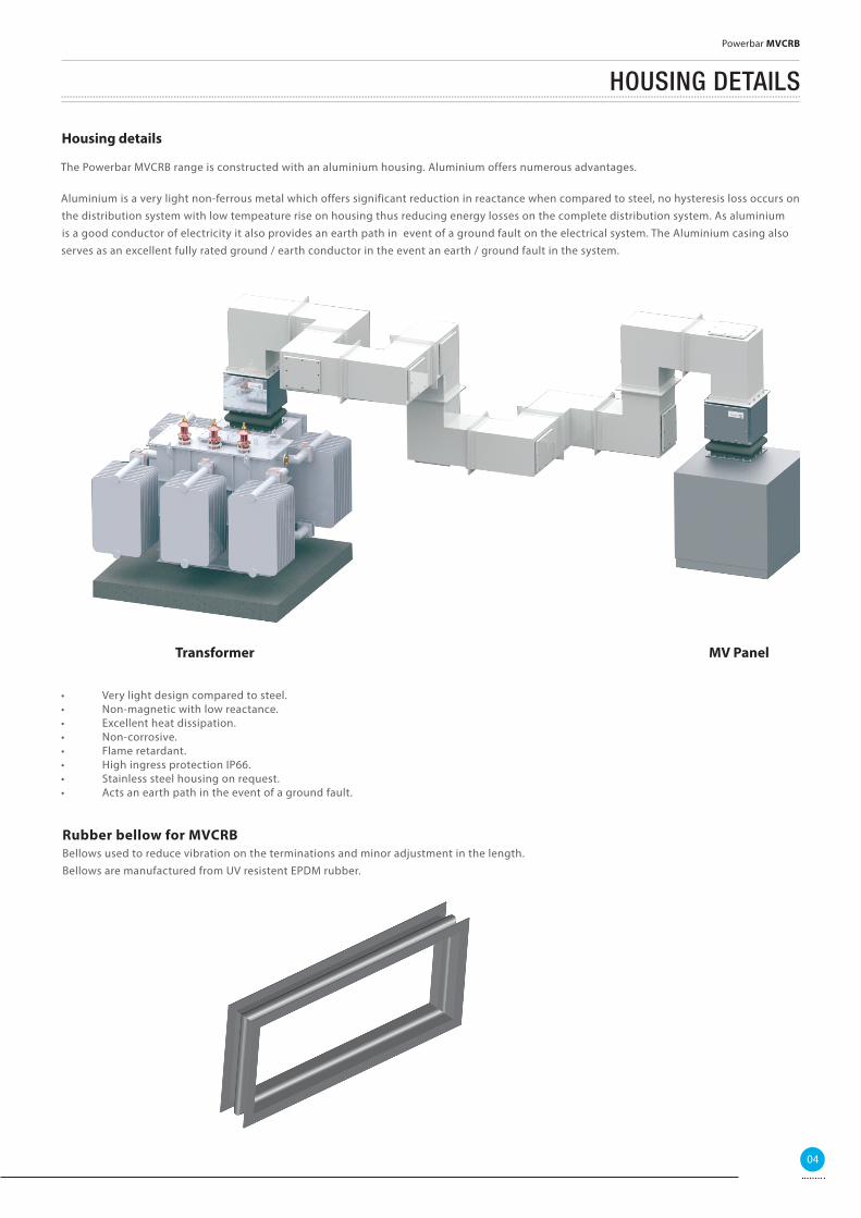
Housing details
The Powerbar MVCRB range is constructed with an aluminium housing. Aluminium offers numerous advantages.
Aluminium is a very light non-ferrous metal which offers significant reduction in reactance when compared to steel, no hysteresis loss occurs on the distribution system with low tempeature rise on housing thus reducing energy losses on the complete distribution system. As aluminium is a good conductor of electricity it also provides an earth path in event of a ground fault on the electrical system. The Aluminium casing also serves as an excellent fully rated ground / earth conductor in the event an earth / ground fault in the system.
Transformer MV Panel
• Very light design compared to steel.• Non-magnetic with low reactance.• Excellent heat dissipation.• Non-corrosive.• Flame retardant.• High ingress protection IP66.• Stainless steel housing on request.• Acts an earth path in the event of a ground fault.
Rubber bellow for MVCRBBellows used to reduce vibration on the terminations and minor adjustment in the length. Bellows are manufactured from UV resistent EPDM rubber.
04
Powerbar MVCRB
STRAIGHT LENGTHS
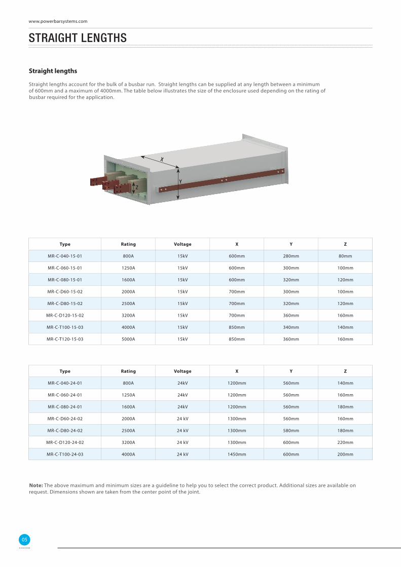
Straight lengths
Straight lengths account for the bulk of a busbar run. Straight lengths can be supplied at any length between a minimum of 600mm and a maximum of 4000mm. The table below illustrates the size of the enclosure used depending on the rating of busbar required for the application.
Type Rating Voltage X Y Z
MR-C-040-15-01 800A 15kV 600mm 280mm 80mm
MR-C-060-15-01 1250A 15kV 600mm 300mm 100mm
MR-C-080-15-01 1600A 15kV 600mm 320mm 120mm
MR-C-D60-15-02 2000A 15kV 700mm 300mm 100mm
MR-C-D80-15-02 2500A 15kV 700mm 320mm 120mm
MR-C-D120-15-02 3200A 15kV 700mm 360mm 160mm
MR-C-T100-15-03 4000A 15kV 850mm 340mm 140mm
MR-C-T120-15-03 5000A 15kV 850mm 360mm 160mm
Type Rating Voltage X Y Z
MR-C-040-24-01 800A 24kV 1200mm 560mm 140mm
MR-C-060-24-01 1250A 24kV 1200mm 560mm 160mm
MR-C-080-24-01 1600A 24kV 1200mm 560mm 180mm
MR-C-D60-24-02 2000A 24 kV 1300mm 560mm 160mm
MR-C-D80-24-02 2500A 24 kV 1300mm 580mm 180mm
MR-C-D120-24-02 3200A 24 kV 1300mm 600mm 220mm
MR-C-T100-24-03 4000A 24 kV 1450mm 600mm 200mm
Note: The above maximum and minimum sizes are a guideline to help you to select the correct product. Additional sizes are available on request. Dimensions shown are taken from the center point of the joint.
Z
X
Y
05
www.powerbarsystems.com
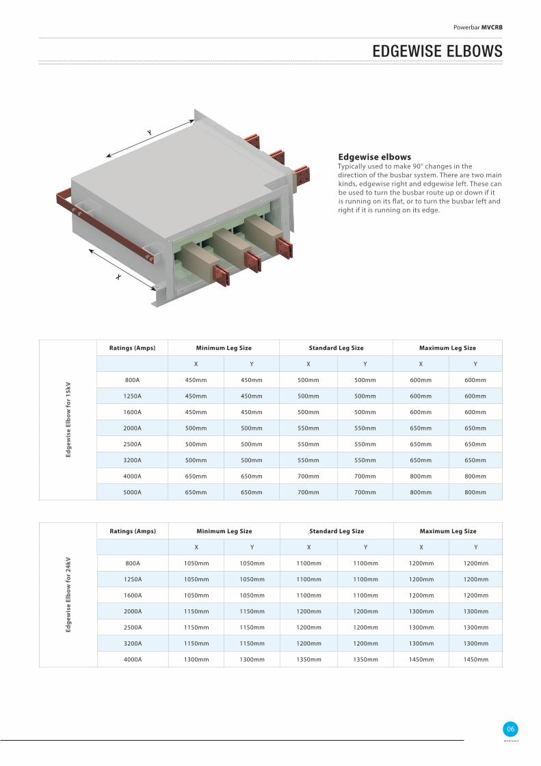
EDGEWISE ELBOWS
Ratings (Amps) Minimum Leg Size Standard Leg Size Maximum Leg Size
X Y X Y X Y
800A 450mm 450mm 500mm 500mm 600mm 600mm
1250A 450mm 450mm 500mm 500mm 600mm 600mm
1600A 450mm 450mm 500mm 500mm 600mm 600mm
2000A 500mm 500mm 550mm 550mm 650mm 650mm
2500A 500mm 500mm 550mm 550mm 650mm 650mm
3200A 500mm 500mm 550mm 550mm 650mm 650mm
4000A 650mm 650mm 700mm 700mm 800mm 800mm
5000A 650mm 650mm 700mm 700mm 800mm 800mm
Edge
wis
e El
bow
for
15kV
Ratings (Amps) Minimum Leg Size Standard Leg Size Maximum Leg Size
X Y X Y X Y
800A 1050mm 1050mm 1100mm 1100mm 1200mm 1200mm
1250A 1050mm 1050mm 1100mm 1100mm 1200mm 1200mm
1600A 1050mm 1050mm 1100mm 1100mm 1200mm 1200mm
2000A 1150mm 1150mm 1200mm 1200mm 1300mm 1300mm
2500A 1150mm 1150mm 1200mm 1200mm 1300mm 1300mm
3200A 1150mm 1150mm 1200mm 1200mm 1300mm 1300mm
4000A 1300mm 1300mm 1350mm 1350mm 1450mm 1450mm
Edge
wis
e El
bow
for
24kV
Edgewise elbowsTypically used to make 90° changes in the direction of the busbar system. There are two main kinds, edgewise right and edgewise left. These can be used to turn the busbar route up or down if it is running on its flat, or to turn the busbar left and right if it is running on its edge.
Y
X
06
Powerbar MVCRB
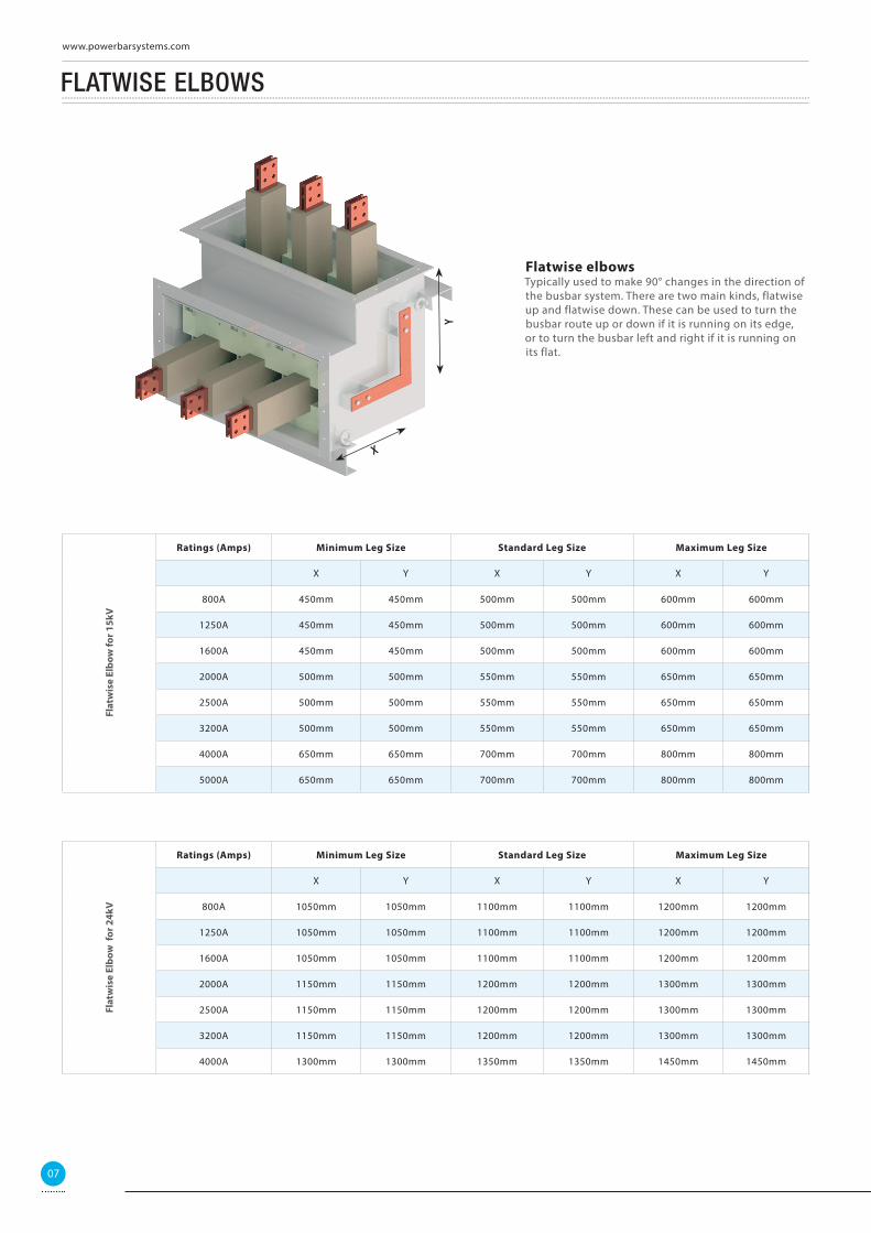
FLATWISE ELBOWS
Ratings (Amps) Minimum Leg Size Standard Leg Size Maximum Leg Size
X Y X Y X Y
800A 450mm 450mm 500mm 500mm 600mm 600mm
1250A 450mm 450mm 500mm 500mm 600mm 600mm
1600A 450mm 450mm 500mm 500mm 600mm 600mm
2000A 500mm 500mm 550mm 550mm 650mm 650mm
2500A 500mm 500mm 550mm 550mm 650mm 650mm
3200A 500mm 500mm 550mm 550mm 650mm 650mm
4000A 650mm 650mm 700mm 700mm 800mm 800mm
5000A 650mm 650mm 700mm 700mm 800mm 800mm
Flat
wis
e El
bow
for 1
5kV
Ratings (Amps) Minimum Leg Size Standard Leg Size Maximum Leg Size
X Y X Y X Y
800A 1050mm 1050mm 1100mm 1100mm 1200mm 1200mm
1250A 1050mm 1050mm 1100mm 1100mm 1200mm 1200mm
1600A 1050mm 1050mm 1100mm 1100mm 1200mm 1200mm
2000A 1150mm 1150mm 1200mm 1200mm 1300mm 1300mm
2500A 1150mm 1150mm 1200mm 1200mm 1300mm 1300mm
3200A 1150mm 1150mm 1200mm 1200mm 1300mm 1300mm
4000A 1300mm 1300mm 1350mm 1350mm 1450mm 1450mm
Flat
wis
e El
bow
for
24k
V
Flatwise elbows Typically used to make 90° changes in the direction of the busbar system. There are two main kinds, flatwise up and flatwise down. These can be used to turn the busbar route up or down if it is running on its edge, or to turn the busbar left and right if it is running on its flat.
YX
07
www.powerbarsystems.com
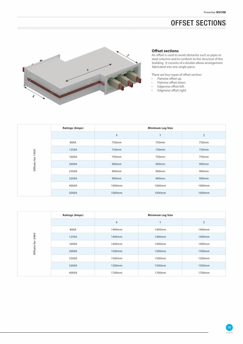
OFFSET SECTIONS
Off set sections An off set is used to avoid obstacles such as pipes or steel columns and to conform to the structure of the building. It consists of a double elbow arrangement fabricated into one single piece.
There are four types of off set section: • Flatwise off set up.• Flatwise off set down.• Edgewise off set left.• Edgewise off set right.
Ratings (Amps) Minimum Leg Size
X Y Z
800A 750mm 750mm 750mm
1250A 750mm 750mm 750mm
1600A 750mm 750mm 750mm
2000A 900mm 900mm 900mm
2500A 900mm 900mm 900mm
3200A 900mm 900mm 900mm
4000A 1000mm 1000mm 1000mm
5000A 1000mm 1000mm 1000mm
Off
sets
for
15kV
Ratings (Amps) Minimum Leg Size
X Y Z
800A 1400mm 1400mm 1400mm
1250A 1400mm 1400mm 1400mm
1600A 1400mm 1400mm 1400mm
2000A 1500mm 1500mm 1500mm
2500A 1500mm 1500mm 1500mm
3200A 1500mm 1500mm 1500mm
4000A 1700mm 1700mm 1700mm
Off
sets
for
24kV
X
Y
Z
08
Powerbar MVCRB
COMBINATION
Combination possibilitiesCombination elbows are used to conform to the buildings structure and to utilise a small amount of space to change direction by combining both fl atwise and edgewise elbows.
• Elbow + off set up• Elbow + off set down• Elbow + off set right• Elbow + off set left
Ratings (Amps) Minimum Leg Size
X Y Z
800A 500mm 750mm 500mm
1250A 500mm 750mm 500mm
1600A 500mm 750mm 500mm
2000A 800mm 850mm 800mm
2500A 800mm 850mm 800mm
3200A 800mm 850mm 800mm
4000A 950mm 1000mm 950mm
5000A 950mm 1000mm 950mm
Off
sets
for 1
5kV
Ratings (Amps) Minimum Leg Size
X Y Z
800A 1100mm 1400mm 1100mm
1250A 1100mm 1400mm 1100mm
1600A 1100mm 1400mm 1100mm
2000A 1500mm 1800mm 1500mm
2500A 1500mm 1800mm 1500mm
3200A 1500mm 1800mm 1500mm
4000A 1600mm 1800mm 1600mm
Off
sets
for 2
4kV
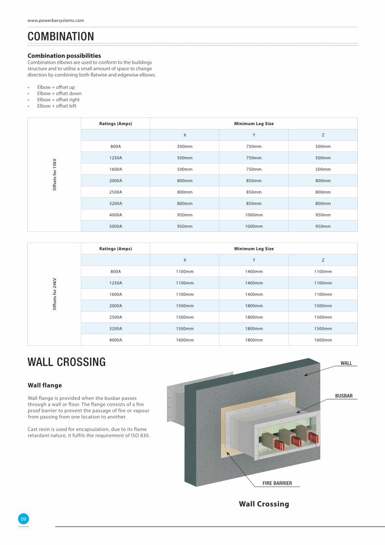
WALL CROSSING
Wall flange
Wall flange is provided when the busbar passes through a wall or floor. The flange consists of a fire proof barrier to prevent the passage of fire or vapour from passing from one location to another.
Cast resin is used for encapsulation, due to its flame retardant nature, it fulfils the requirement of ISO 830.
WALL
BUSBAR
FIRE BARRIER
Wall Crossing
09
www.powerbarsystems.com
FLANGES AND ADAPTER BOX
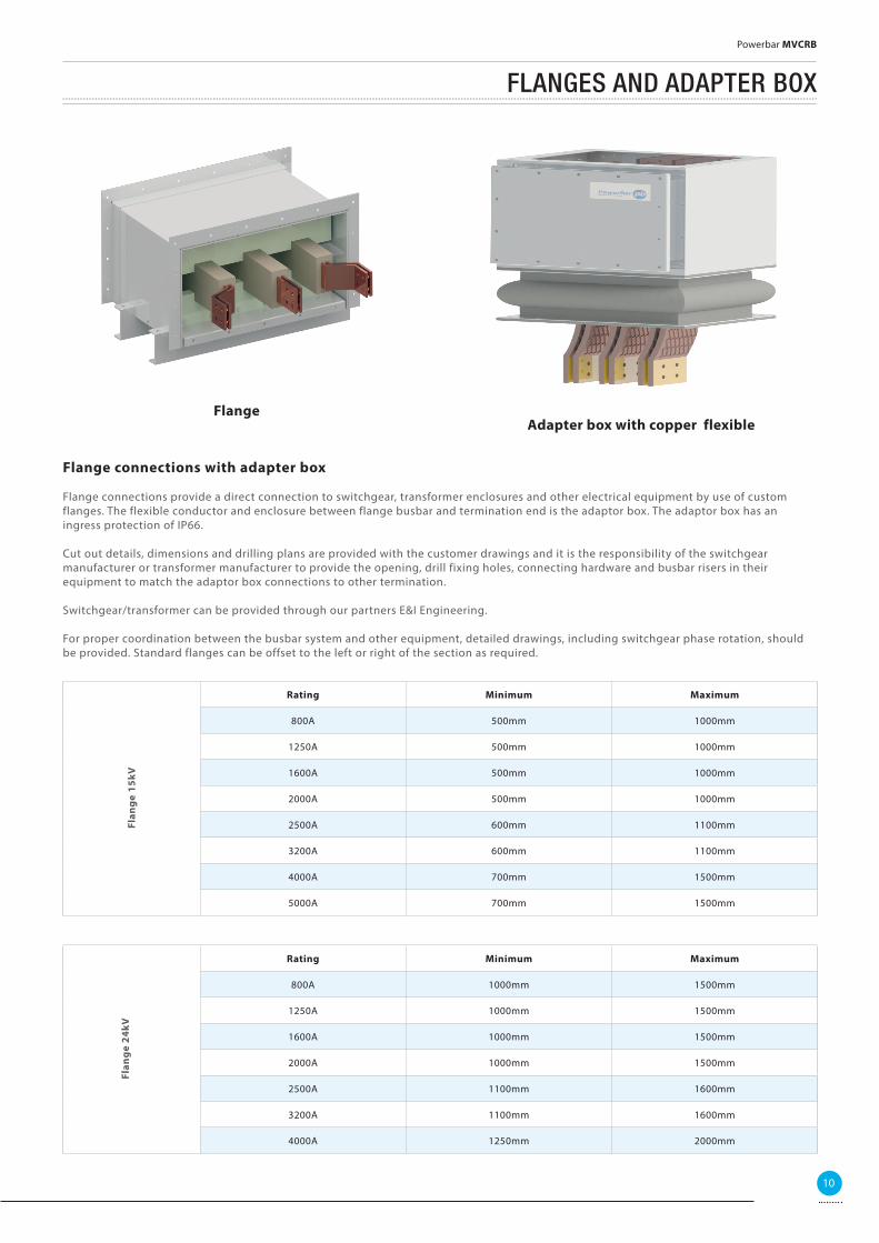
Flange connections with adapter box
Flange connections provide a direct connection to switchgear, transformer enclosures and other electrical equipment by use of custom flanges. The flexible conductor and enclosure between flange busbar and termination end is the adaptor box. The adaptor box has an ingress protection of IP66.
Cut out details, dimensions and drilling plans are provided with the customer drawings and it is the responsibility of the switchgear manufacturer or transformer manufacturer to provide the opening, drill fixing holes, connecting hardware and busbar risers in their equipment to match the adaptor box connections to other termination.
Switchgear/transformer can be provided through our partners E&I Engineering.
For proper coordination between the busbar system and other equipment, detailed drawings, including switchgear phase rotation, should be provided. Standard flanges can be offset to the left or right of the section as required.
Rating Minimum Maximum
800A 500mm 1000mm
1250A 500mm 1000mm
1600A 500mm 1000mm
2000A 500mm 1000mm
2500A 600mm 1100mm
3200A 600mm 1100mm
4000A 700mm 1500mm
5000A 700mm 1500mm
Flan
ge
15kV
Rating Minimum Maximum
800A 1000mm 1500mm
1250A 1000mm 1500mm
1600A 1000mm 1500mm
2000A 1000mm 1500mm
2500A 1100mm 1600mm
3200A 1100mm 1600mm
4000A 1250mm 2000mm
Flan
ge
24kV
FlangeAdapter box with copper flexible
10
Powerbar MVCRB
COMBINATION FLANGES
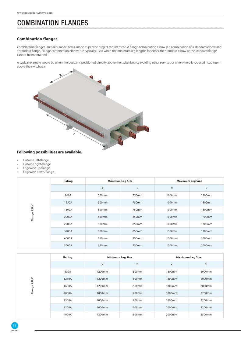
Combination flanges
Combination fl anges are tailor made items, made as per the project requirement. A fl ange combination elbow is a combination of a standard elbow and a standard fl ange. Flange combination elbows are typically used when the minimum leg lengths for either the standard elbow or the standard fl ange cannot be maintained.
A typical example would be when the busbar is positioned directly above the switchboard, avoiding other services or when there is reduced head room above the switchgear.
Following possibilities are available.
• Flatwise left/fl ange• Flatwise right/fl ange• Edgewise up/fl ange• Edgewise down/fl ange
Rating Minimum Leg Size Maximum Leg Size
X Y X Y
800A 500mm 750mm 1000mm 1500mm
1250A 500mm 750mm 1000mm 1500mm
1600A 500mm 750mm 1000mm 1500mm
2000A 500mm 850mm 1000mm 1700mm
2500A 500mm 850mm 1000mm 1700mm
3200A 500mm 850mm 1500mm 1700mm
4000A 650mm 950mm 1500mm 2000mm
5000A 650mm 950mm 1500mm 2000mm
Flan
ge
15kV
Rating Minimum Leg Size Maximum Leg Size
X Y X Y
800A 1200mm 1500mm 1800mm 2000mm
1250A 1200mm 1500mm 1800mm 2000mm
1600A 1200mm 1500mm 1800mm 2000mm
2000A 1000mm 1700mm 1800mm 2200mm
2500A 1000mm 1700mm 1800mm 2200mm
3200A 1000mm 1700mm 2000mm 2200mm
4000A 1200mm 1800mm 2000mm 2500mm
Flan
ge
24kV
e switchgear.
ng possibilities are available.
X
Y
11
www.powerbarsystems.com
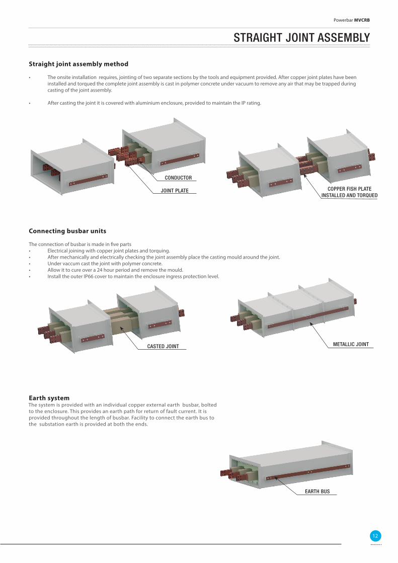
Straight joint assembly method
• The onsite installation requires, jointing of two separate sections by the tools and equipment provided. After copper joint plates have been installed and torqued the complete joint assembly is cast in polymer concrete under vacuum to remove any air that may be trapped during casting of the joint assembly.
• After casting the joint it is covered with aluminium enclosure, provided to maintain the IP rating.
Connecting busbar units
The connection of busbar is made in fi ve parts• Electrical joining with copper joint plates and torquing.• After mechanically and electrically checking the joint assembly place the casting mould around the joint.• Under vaccum cast the joint with polymer concrete.• Allow it to cure over a 24 hour period and remove the mould.• Install the outer IP66 cover to maintain the enclosure ingress protection level.
STRAIGHT JOINT ASSEMBLY
Earth systemThe system is provided with an individual copper external earth busbar, bolted to the enclosure. This provides an earth path for return of fault current. It is provided throughout the length of busbar. Facility to connect the earth bus to the substation earth is provided at both the ends.
EARTH BUS
COPPER FISH PLATE
INSTALLED AND TORQUED
CONDUCTOR
JOINT PLATE
METALLIC JOINTCASTED JOINT
12
Powerbar MVCRB
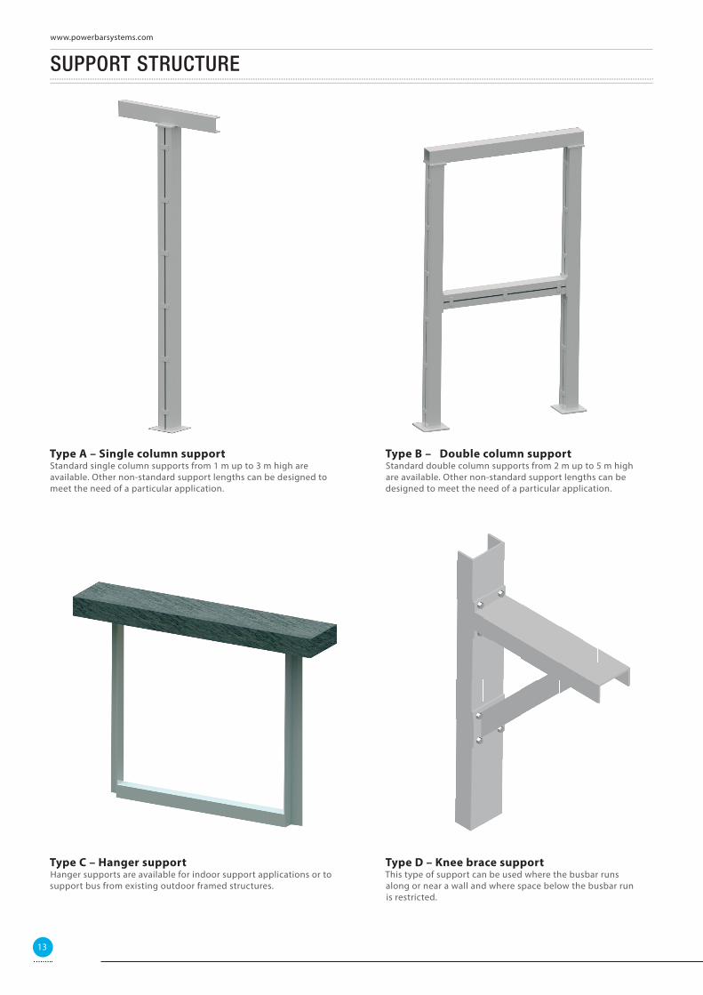
SUPPORT STRUCTURE
Type A – Single column supportStandard single column supports from 1 m up to 3 m high are available. Other non-standard support lengths can be designed to meet the need of a particular application.
Type D – Knee brace supportThis type of support can be used where the busbar runs along or near a wall and where space below the busbar run is restricted.
Type C – Hanger supportHanger supports are available for indoor support applications or to support bus from existing outdoor framed structures.
13
www.powerbarsystems.com
Type B – Double column supportStandard double column supports from 2 m up to 5 m high are available. Other non-standard support lengths can be designed to meet the need of a particular application.
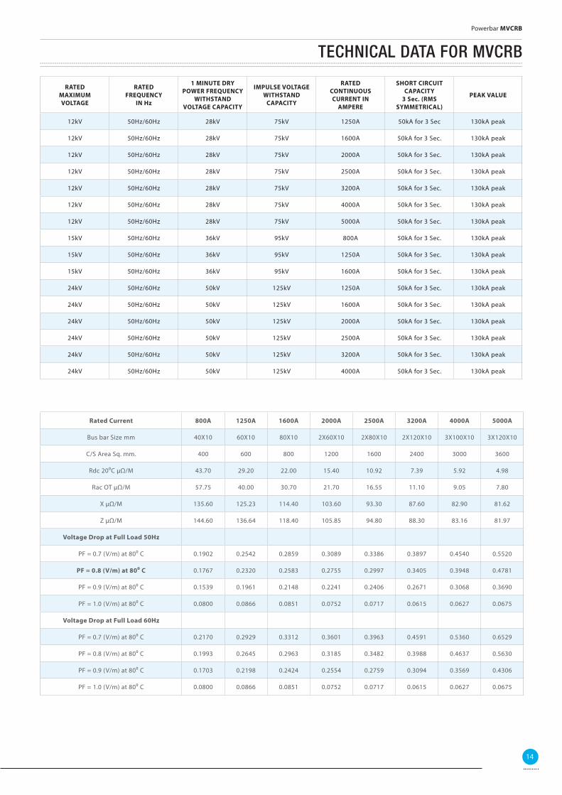
TECHNICAL DATA FOR MVCRB
RATEDMAXIMUMVOLTAGE
RATEDFREQUENCY
IN Hz
1 MINUTE DRY POWER FREQUENCY
WITHSTAND VOLTAGE CAPACITY
IMPULSE VOLTAGE WITHSTAND
CAPACITY
RATED CONTINUOUS CURRENT IN
AMPERE
SHORT CIRCUIT CAPACITY
3 Sec. (RMS SYMMETRICAL)
PEAK VALUE
12kV 50Hz/60Hz 28kV 75kV 1250A 50kA for 3 Sec 130kA peak
12kV 50Hz/60Hz 28kV 75kV 1600A 50kA for 3 Sec. 130kA peak
12kV 50Hz/60Hz 28kV 75kV 2000A 50kA for 3 Sec. 130kA peak
12kV 50Hz/60Hz 28kV 75kV 2500A 50kA for 3 Sec. 130kA peak
12kV 50Hz/60Hz 28kV 75kV 3200A 50kA for 3 Sec. 130kA peak
12kV 50Hz/60Hz 28kV 75kV 4000A 50kA for 3 Sec. 130kA peak
12kV 50Hz/60Hz 28kV 75kV 5000A 50kA for 3 Sec. 130kA peak
15kV 50Hz/60Hz 36kV 95kV 800A 50kA for 3 Sec. 130kA peak
15kV 50Hz/60Hz 36kV 95kV 1250A 50kA for 3 Sec. 130kA peak
15kV 50Hz/60Hz 36kV 95kV 1600A 50kA for 3 Sec. 130kA peak
24kV 50Hz/60Hz 50kV 125kV 1250A 50kA for 3 Sec. 130kA peak
24kV 50Hz/60Hz 50kV 125kV 1600A 50kA for 3 Sec. 130kA peak
24kV 50Hz/60Hz 50kV 125kV 2000A 50kA for 3 Sec. 130kA peak
24kV 50Hz/60Hz 50kV 125kV 2500A 50kA for 3 Sec. 130kA peak
24kV 50Hz/60Hz 50kV 125kV 3200A 50kA for 3 Sec. 130kA peak
24kV 50Hz/60Hz 50kV 125kV 4000A 50kA for 3 Sec. 130kA peak
14
Powerbar MVCRB
Rated Current 800A 1250A 1600A 2000A 2500A 3200A 4000A 5000A
Bus bar Size mm 40X10 60X10 80X10 2X60X10 2X80X10 2X120X10 3X100X10 3X120X10
C/S Area Sq. mm. 400 600 800 1200 1600 2400 3000 3600
Rdc 200C μΩ/M 43.70 29.20 22.00 15.40 10.92 7.39 5.92 4.98
Rac OT μΩ/M 57.75 40.00 30.70 21.70 16.55 11.10 9.05 7.80
X μΩ/M 135.60 125.23 114.40 103.60 93.30 87.60 82.90 81.62
Z μΩ/M 144.60 136.64 118.40 105.85 94.80 88.30 83.16 81.97
Voltage Drop at Full Load 50Hz
PF = 0.7 (V/m) at 800 C 0.1902 0.2542 0.2859 0.3089 0.3386 0.3897 0.4540 0.5520
PF = 0.8 (V/m) at 800 C 0.1767 0.2320 0.2583 0.2755 0.2997 0.3405 0.3948 0.4781
PF = 0.9 (V/m) at 800 C 0.1539 0.1961 0.2148 0.2241 0.2406 0.2671 0.3068 0.3690
PF = 1.0 (V/m) at 800 C 0.0800 0.0866 0.0851 0.0752 0.0717 0.0615 0.0627 0.0675
Voltage Drop at Full Load 60Hz
PF = 0.7 (V/m) at 800 C 0.2170 0.2929 0.3312 0.3601 0.3963 0.4591 0.5360 0.6529
PF = 0.8 (V/m) at 800 C 0.1993 0.2645 0.2963 0.3185 0.3482 0.3988 0.4637 0.5630
PF = 0.9 (V/m) at 800 C 0.1703 0.2198 0.2424 0.2554 0.2759 0.3094 0.3569 0.4306
PF = 1.0 (V/m) at 800 C 0.0800 0.0866 0.0851 0.0752 0.0717 0.0615 0.0627 0.0675
OTHER BROCHURES
Please use the QR codes on this page to gain access to our other brochures.To read the QR codes you will need a device with a QR code reader.These brochures can also be accessed through our website.
Switchgear
From out partners at E&I Engineering
Product Overview
HPB Copper
HPB Aluminium
HPB IEC Copper
HPB ADDC Copper
MPB Busbar System
Cast Resin Bar
Tap Off Units
MVSPB/NSPB
MVCRB
MV Catalogue
www.powerbarsystems.com

website: www.powerbarsystems.com
Powerbar Limited has a policy of continuous development and therefore has the right to supply a product which may diff er in detail from those shown in this publication.
Website:www.e-i-eng.comwww.powerbarsystems.comEmail:[email protected]@[email protected]@powerbargulf.ae
E&I Engineering CorporationUSA Manufacturing Location400 Supreme DriveAndersonSouth Carolina29621Tel:
+1 864-375-1760
E&I Engineering LTDEuropean Manufacturing LocationBallyderowenBurnfootLiff ordCo.DonegalIrelandTel:(UK) +44(0)2871353030
(ROI) +353)0)749368106
Powerbar LLCMiddle East Manufacturing LocationN16/N17Al Ghail Industrial ParkRas Al KhaimahPO Box 31921Tel:
+971(0)72216100
E&I Engineering LTDUK Central Offi ce2/8 Victoria AvenueLondonEC2M4NSTel:
+44(0)2032061650