Embed Size (px)
Citation preview
Power ElectronicsPower Electronics
Chapter 6 AC to AC Converters( AC Controllers and
Frequency Converters )
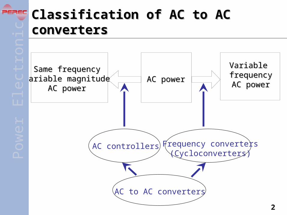
Classification of AC to AC convertersClassification of AC to AC converters
Same frequencySame frequencyvariable magnitudevariable magnitude
AC powerAC powerAC powerAC power
Variable Variable frequencyfrequencyAC powerAC power
AC controllers Frequency converters(Cycloconverters)
AC to AC converters
Pow
erE
lec t
roni
cs
2
Pow
erE
lec t
roni
cs
3
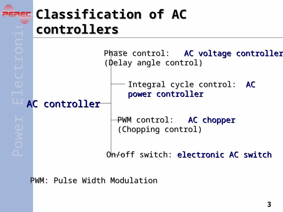
Classification of AC controllersClassification of AC controllers
AC controllerAC controller
Phase control: Phase control: AC voltage controllerAC voltage controller(Delay angle control)(Delay angle control)
Integral cycle control: Integral cycle control: AC power controllerAC power controller
PWM control: PWM control: AC chopperAC chopper(Chopping control)(Chopping control)
On/off switch: On/off switch: electronic AC switchelectronic AC switch
PWM: Pulse Width ModulationPWM: Pulse Width Modulation

Classification of frequency convertersClassification of frequency converters
Frequency converterFrequency converter(Cycloconverter)(Cycloconverter)
Phase control: Phase control: thyristor cycloconverterthyristor cycloconverter(Delay angle control)(Delay angle control)
PWM control: PWM control: matrix convertermatrix converter(Chopping control)(Chopping control)
Pow
erE
lec t
roni
cs
Cycloconverter is sometimes referred to Cycloconverter is sometimes referred to – in a broader sensein a broader sense—any ordinary AC to AC converter—any ordinary AC to AC converter– in a narrower sense—thyristor cycloconverterin a narrower sense—thyristor cycloconverter
4
Pow
erE
lec t
roni
cs
5
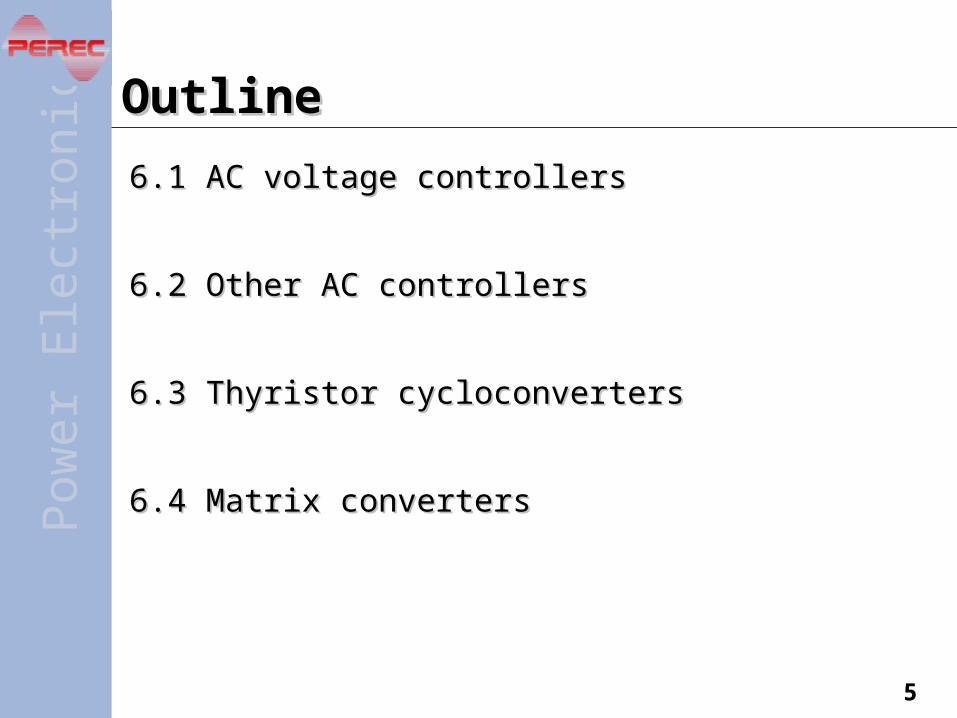
OutlineOutline
6.1 AC voltage controllers6.1 AC voltage controllers
6.2 Other AC controllers 6.2 Other AC controllers
6.3 Thyristor cycloconverters6.3 Thyristor cycloconverters
6.4 Matrix converters6.4 Matrix converters

Pow
erE
lec t
roni
cs
6
6.1 AC voltage controllers6.1 AC voltage controllers
6.1.1 Single-phase AC voltage controller6.1.1 Single-phase AC voltage controller
6.1.2 Three-phase AC voltage controller6.1.2 Three-phase AC voltage controller
ApplicationsApplications
Lighting controlLighting control
Soft-start of asynchronous motorsSoft-start of asynchronous motors
Adjustable speed drive of asynchronous motorsAdjustable speed drive of asynchronous motors
Reactive power controlReactive power control
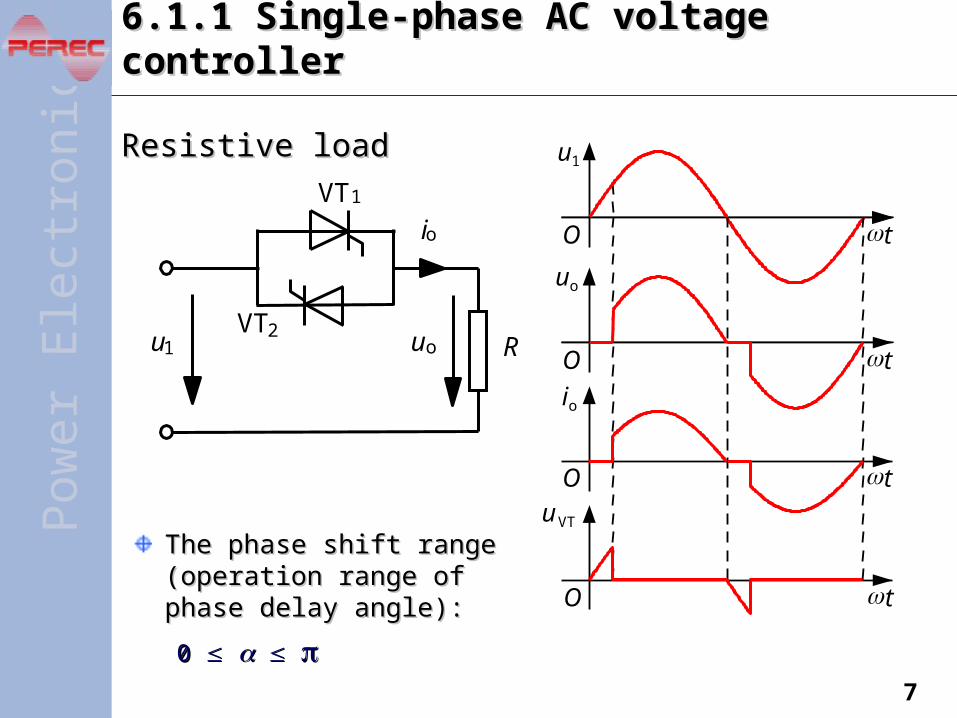
6.1.1 Single-phase AC voltage controller6.1.1 Single-phase AC voltage controller
The phase shift range The phase shift range (operation range of phase (operation range of phase delay angle):delay angle):
0 0
Resistive loadResistive load
Pow
erE
lec t
roni
cs
Ru1 uo
io
VT1
VT2
O
u1
uo
io
uVT
t
O t
O t
O t
7
Pow
erE
lec t
roni
cs
8
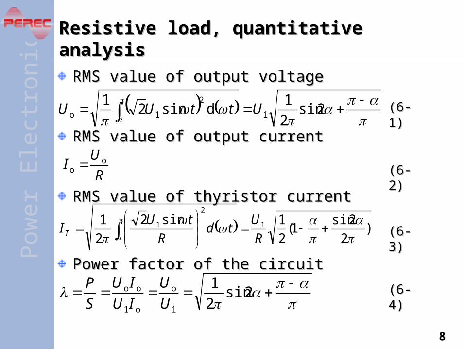
RMS value of output voltageRMS value of output voltage
RMS value of output currentRMS value of output current
RMS value of thyristor currentRMS value of thyristor current
Power factor of the circuitPower factor of the circuit
Resistive load, quantitative analysisResistive load, quantitative analysis
2sin
2
1dsin2
11
2
1o UttUU
R
UI o
o
)2
2sin1(
2
1sin2
2
1 1
2
1
R
Utd
R
tUIT
2sin2
1
1
o
o1
oo
U
U
IU
IU
S
P
(6-1)(6-1)
(6-2)(6-2)
(6-3)(6-3)
(6-4)(6-4)
Pow
erE
lec t
roni
cs
9
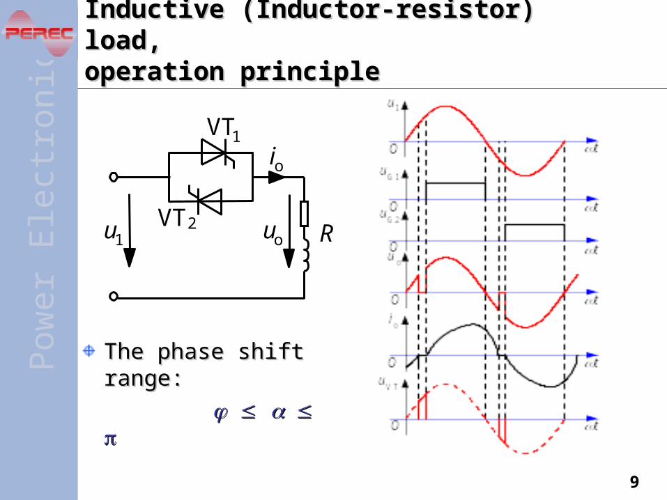
Inductive (Inductor-resistor) load, Inductive (Inductor-resistor) load, operation principleoperation principle
The phase shift The phase shift range:range:
Ru1 uo
io
VT1
VT2
Pow
erE
lec t
roni
cs
10
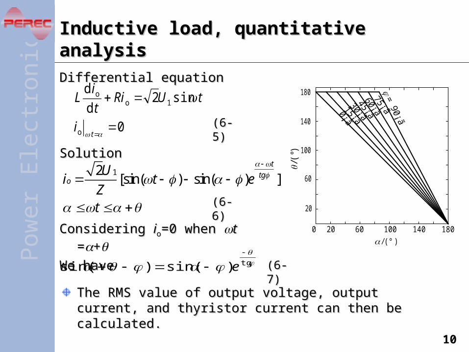
Differential equationDifferential equation
SolutionSolution
Considering Considering iioo=0 when =0 when tt==++
We haveWe have
Inductive load, quantitative analysisInductive load, quantitative analysis
The RMS value of output voltage, output current, and thyristor The RMS value of output voltage, output current, and thyristor current can then be calculated. current can then be calculated.
0
sin2d
d
o
1oo
ti
tURit
iL
(6-5)(6-5)
0 20 10060 140 180
20
100
4-3图
60
/(
°)
180
140
/(° )
(6-6)(6-6)
tg)sin()sin(
e (6-7)(6-7)
12[sin( ) sin( ) ]
t
tgo
Ui t e
Zt
Pow
erE
lec t
roni
cs
11
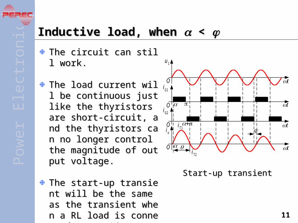
Inductive load, when Inductive load, when < <
The circuit can still work.The circuit can still work.
The load current will be coThe load current will be continuous just like the thyristntinuous just like the thyristors are short-circuit, and thors are short-circuit, and the thyristors can no longer ce thyristors can no longer control the magnitude of outontrol the magnitude of output voltage. put voltage.
The start-up transient will bThe start-up transient will be the same as the transient e the same as the transient when a RL load is connectwhen a RL load is connected to an AC source at ed to an AC source at t t == < <
t
t
t
t
4-5图
O
O
O
O
u 1
iG1
iG2
io iT1
iT2
Start-up transientStart-up transient

Harmonic analysisHarmonic analysisThere is no DC component There is no DC component and even order harmonics in and even order harmonics in the current.the current.– The current waveform is half-The current waveform is half-
wave symmetric.wave symmetric.
The higher the number of The higher the number of harmonic ordinate, the lower harmonic ordinate, the lower the harmonic content.the harmonic content.
is when harmonics is when harmonics is the most severe. is the most severe.
The situation for the inductive The situation for the inductive load is similar to that for the load is similar to that for the resistive load except that the resistive load except that the corresponding harmonic corresponding harmonic content is lower and is even content is lower and is even lower as lower as is increasing. is increasing.
Pow
erE
lec t
roni
cs
Current harmonics Current harmonics for the resistive loadfor the resistive load
0 60 120 180
Fundamental
3
5
7
/ ( °)
In/I
*/%
20
40
60
80
100
12
Pow
erE
lec t
roni
cs
13
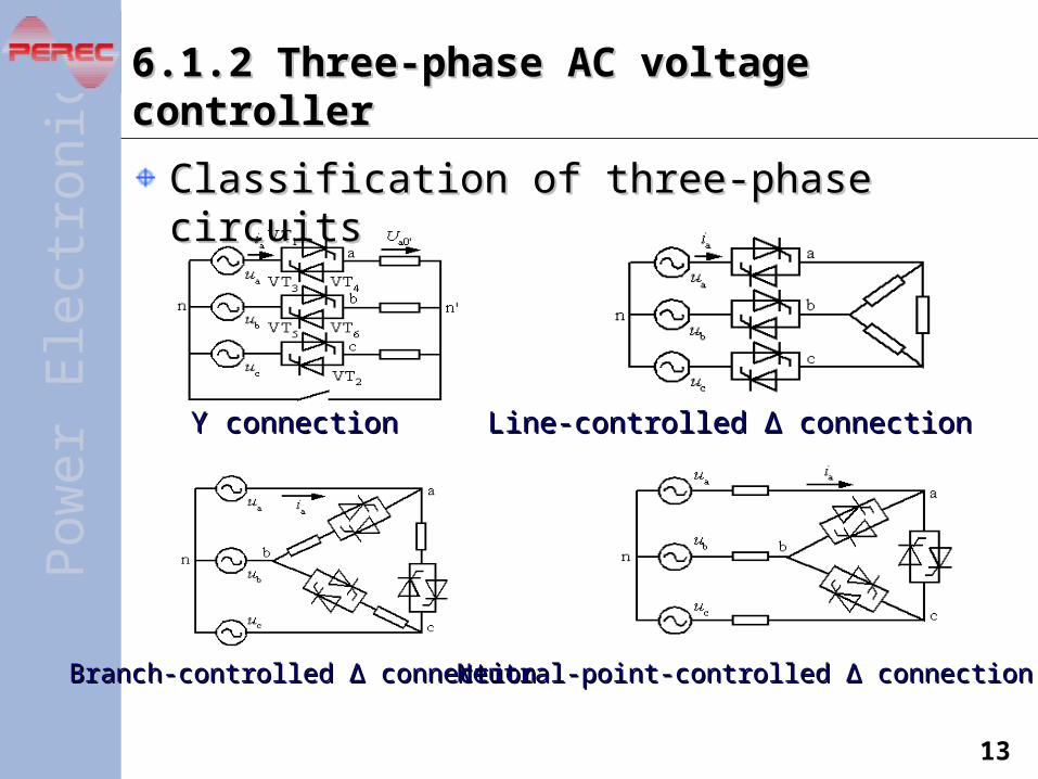
6.1.2 Three-phase AC voltage controller6.1.2 Three-phase AC voltage controller
Classification of three-phase circuitsClassification of three-phase circuits
Y connectionY connection Line-controlled Line-controlled ∆ connection∆ connection
Branch-controlled Branch-controlled ∆ connection∆ connection Neutral-point-controlled Neutral-point-controlled ∆ connection∆ connection
Pow
erE
lec t
roni
cs
14
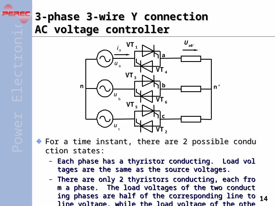
3-phase 3-wire Y connection 3-phase 3-wire Y connection AC voltage controllerAC voltage controller
For a time instant, there are 2 possible conduction states:For a time instant, there are 2 possible conduction states:– Each phase has a thyristor conducting. Load voltages are the saEach phase has a thyristor conducting. Load voltages are the sa
me as the source voltages.me as the source voltages.
– There are only 2 thyristors conducting, each from a phase. The lThere are only 2 thyristors conducting, each from a phase. The load voltages of the two conducting phases are half of the correspoad voltages of the two conducting phases are half of the corresponding line to line voltage, while the load voltage of the other phaonding line to line voltage, while the load voltage of the other phase is 0.se is 0.
n n '
a
b
c
uuaa
uubb
uucc
ii aa
Ua0'
VT 5
VT3
VT 6
VT 4
VT 2
VT 1
Pow
erE
lec t
roni
cs
15
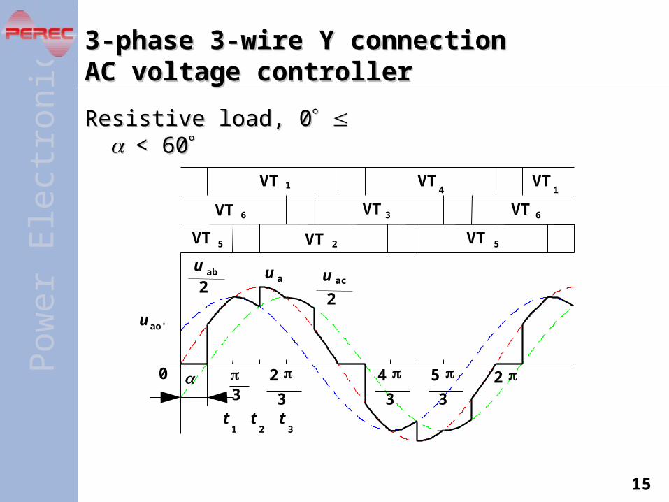
3-phase 3-wire Y connection 3-phase 3-wire Y connection AC voltage controllerAC voltage controller
Resistive load, 0Resistive load, 0 < 60< 60
4
3
2
3
5
3
3
0 2
u ao'
u au ab
2u ac
2
t1t2t3
VT 1
VT 3 VT 6
VT4
VT 6
VT 2 VT 5VT 5
VT1
Pow
erE
lec t
roni
cs
16
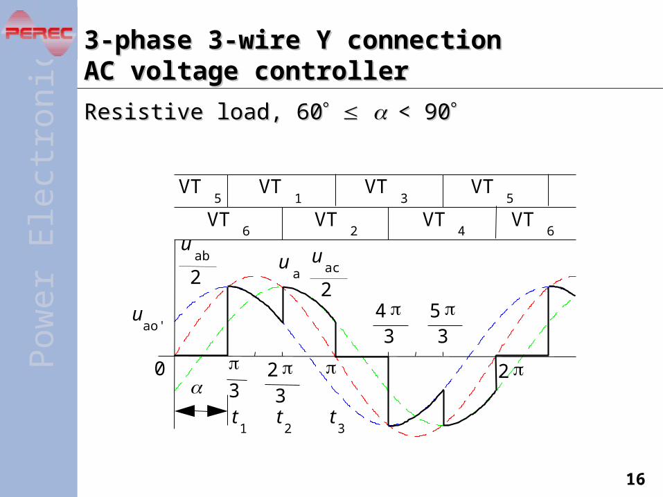
3-phase 3-wire Y connection 3-phase 3-wire Y connection AC voltage controllerAC voltage controller
Resistive load, 60Resistive load, 60 < 90< 90
4 3
2 3
5 3
3
0 2
uao'
ua
uab
2u
ac
2
t1
t2
t3
VT5
VT1
VT3
VT4
VT6
VT2
VT6
VT5
Pow
erE
lec t
roni
cs
17
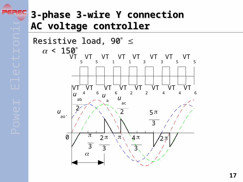
3-phase 3-wire Y connection 3-phase 3-wire Y connection AC voltage controllerAC voltage controller
Resistive load, 90Resistive load, 90 < < 150150
4
3
2
3
5
3
3
0 2
uao'
ua
uab
2
uac
2
VT5
VT1
VT3
VT4
VT6
VT2
VT6
VT5
VT5
VT1
VT3
VT5
VT4
VT2
VT4VT
6
Pow
erE
lec t
roni
cs
18
6.2 Other AC controllers6.2 Other AC controllers
6.2.1 Integral cycle control6.2.1 Integral cycle control—AC power controller—AC power controller
6.2.2 Electronic AC switch6.2.2 Electronic AC switch
6.2.3 Chopping control6.2.3 Chopping control—AC chopper—AC chopper

Pow
erE
lec t
roni
cs
19
6.2.1 Integral cycle control6.2.1 Integral cycle control —AC power controller —AC power controller
Circuit topologies are the same as AC voltage contrCircuit topologies are the same as AC voltage controllers. Only the control method is different.ollers. Only the control method is different.
Load voltage and current are both sinusoidal when tLoad voltage and current are both sinusoidal when thyristors are conducting. hyristors are conducting.
M
Line periodLine period
Control period =M *Line period =2
4M
O
ConductionConductionangleangle =2N
M
3M
2M
uo
u1uo,io
t
U12
Ru1 uo
io
VT1
VT2
Pow
erE
lec t
roni
cs
20
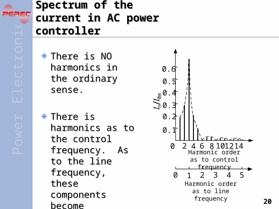
Spectrum of the current in Spectrum of the current in AC power controllerAC power controller
There is NO There is NO harmonics in the harmonics in the ordinary sense. ordinary sense.
There is harmonics There is harmonics as to the control as to the control frequency. As to the frequency. As to the line frequency, these line frequency, these components become components become fractional harmonics.fractional harmonics.
Harmonic order as to control frequency
Harmonic order as to line frequency
0 51 2 3 4
0 12 142 4 6 108
0.6
0.5
0.4
0.3
0.2
0.1
I n/I 0
m
Pow
erE
lec t
roni
cs
21
6.2.2 Electronic AC switch6.2.2 Electronic AC switch
Circuit topologies are the same as AC voltagCircuit topologies are the same as AC voltage controllers. But the back-to-back thyristors e controllers. But the back-to-back thyristors are just used like a switch to turn the equipmare just used like a switch to turn the equipment on or off.ent on or off.

Pow
erE
lec t
roni
cs
22
6.2.3 Chopping control6.2.3 Chopping control—AC chopper—AC chopper
Principle of chopping controlPrinciple of chopping controlThe mean output voltage over The mean output voltage over one switching cycle is one switching cycle is proportional to the duty cycle proportional to the duty cycle in that period. This is also in that period. This is also called called Pulse Width Modulation Pulse Width Modulation (PWM)(PWM)..
AdvantagesAdvantagesMuch better output waveforms, Much better output waveforms, much lower harmonicsmuch lower harmonics
For resistive load, the For resistive load, the displacement factor is always displacement factor is always 1.1.
Waveforms when the load Waveforms when the load is pure resistoris pure resistor
Pow
erE
lec t
roni
cs
23
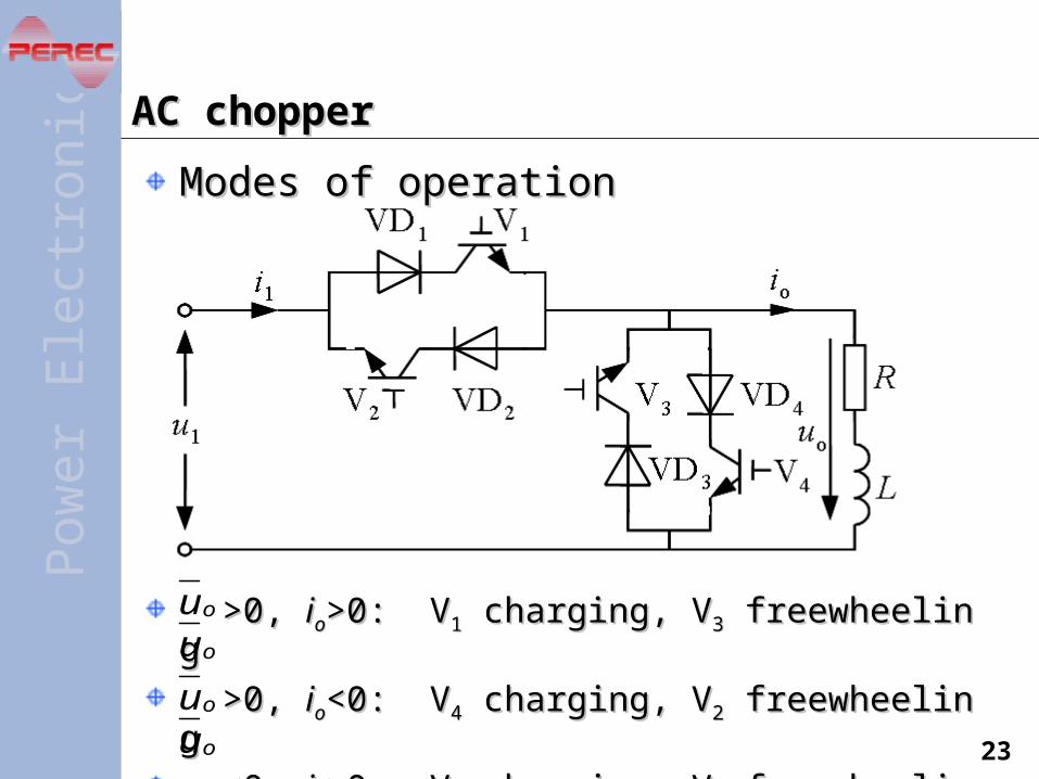
AC chopperAC chopper
Modes of operationModes of operation
>0, >0, iioo>0: V>0: V11 charging, V charging, V33 freewheeling freewheeling
>0, >0, iioo<0: V<0: V44 charging, V charging, V22 freewheeling freewheeling
<0, <0, iioo>0: V>0: V33 charging, V charging, V11 freewheeling freewheeling
<0, <0, iioo<0: V<0: V22 charging, V charging, V44 freewheeling freewheeling
ou
ouou
ou
Pow
erE
lec t
roni
cs
24
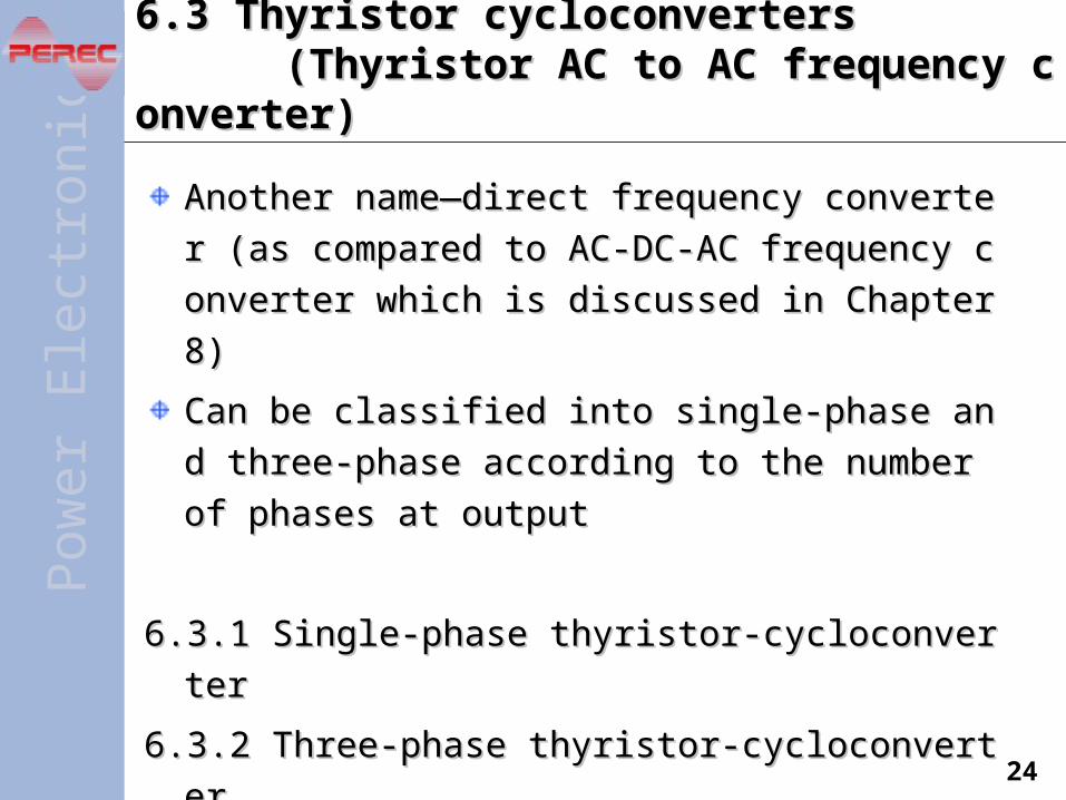
6.3 Thyristor cycloconverters 6.3 Thyristor cycloconverters (Thyristor AC to AC frequency converter) (Thyristor AC to AC frequency converter)
Another name—direct frequency converter (as comAnother name—direct frequency converter (as com
pared to AC-DC-AC frequency converter which is dipared to AC-DC-AC frequency converter which is di
scussed in Chapter 8)scussed in Chapter 8)
Can be classified into single-phase and three-phase Can be classified into single-phase and three-phase
according to the number of phases at outputaccording to the number of phases at output
6.3.1 Single-phase thyristor-cycloconverter6.3.1 Single-phase thyristor-cycloconverter
6.3.2 Three-phase thyristor-cycloconverter6.3.2 Three-phase thyristor-cycloconverter

Pow
erE
lec t
roni
cs
25
6.3.1 Single-phase thyristor-cycloconverter6.3.1 Single-phase thyristor-cycloconverter
Circuit configuration and operation principleCircuit configuration and operation principle
Z
P N
uo
O
uoP=0
P= 2
P=
2
t
Output voltage
Average output voltage
Pow
erE
lec t
roni
cs
26
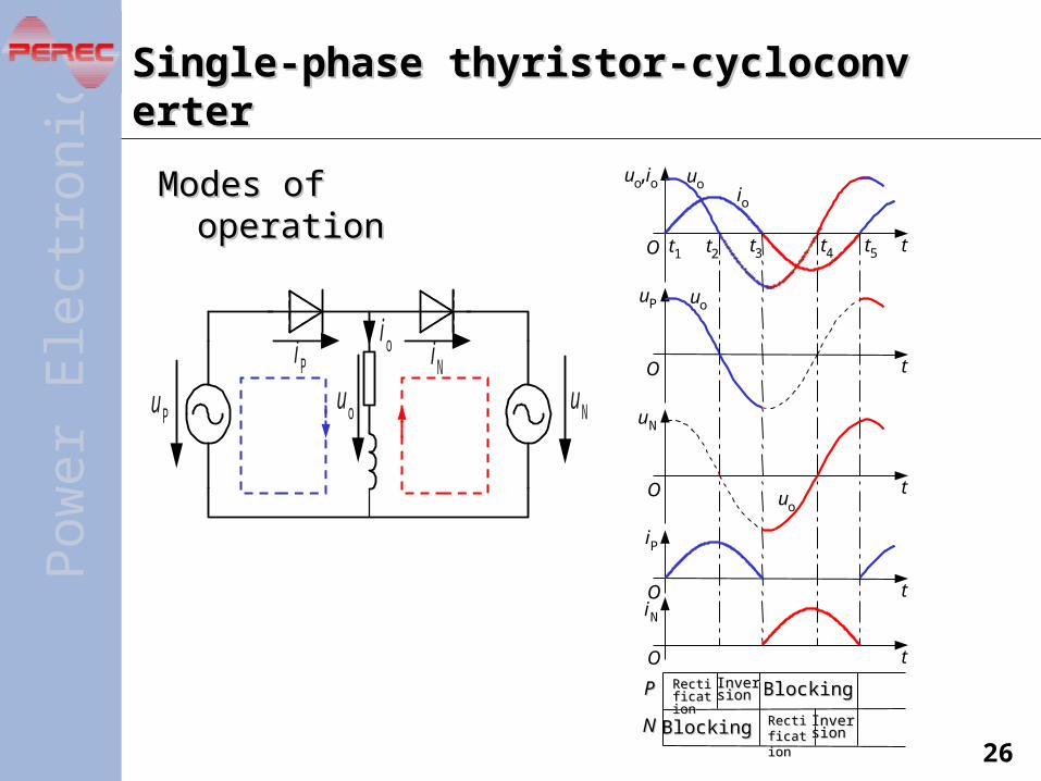
Single-phase thyristor-cycloconverterSingle-phase thyristor-cycloconverter
Modes of operationModes of operation
t
t
t
t
t
O
O
O
O
O
uo,io uoio
t1 t2 t3 t4 t5
uouP
uN
uo
iP
iN
RectifiRectificationcation
InverInversionsion
BlockingBlockingPP
NN
InverInversionsion
BlockingBlocking
RectifiRectificationcation
u Pu Nu o
io iNiP
Pow
erE
lec t
roni
cs
27
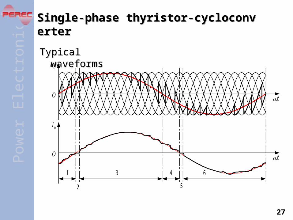
Single-phase thyristor-cycloconverterSingle-phase thyristor-cycloconverter
Typical waveformsTypical waveforms
1
O
O
2
3 4
5
6
4-20图
u o
io
t
t
Pow
erE
lec t
roni
cs
28
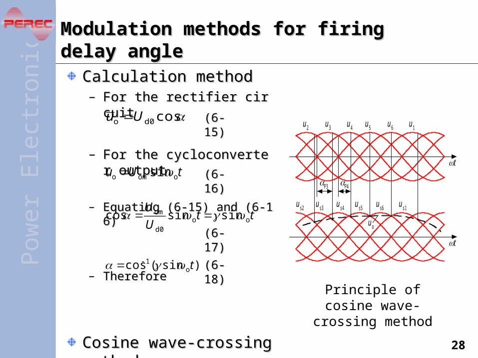
Calculation methodCalculation method– For the rectifier circuitFor the rectifier circuit
– For the cycloconverter outpuFor the cycloconverter outputt
– Equating (6-15) and (6-16)Equating (6-15) and (6-16)
– ThereforeTherefore
Cosine wave-crossing metCosine wave-crossing methodhod
Modulation methods for firing delay angleModulation methods for firing delay angle
Principle of cosine wave-crossing method
4-21图
u 2 u 3 u 4 u 5 u 6 u 1
u s2 u s3 u s4 u s5 u s6 u s1
u o
P3 P4
t
t
cosd0o Uu
tUu oomo sin
ttU
Uoo
d0
om sinsincos
)sin(cos o1 t
(6-(6-15)15)
(6-(6-16)16)
(6-(6-17)17)
(6-(6-18)18)
Pow
erE
lec t
roni
cs
29
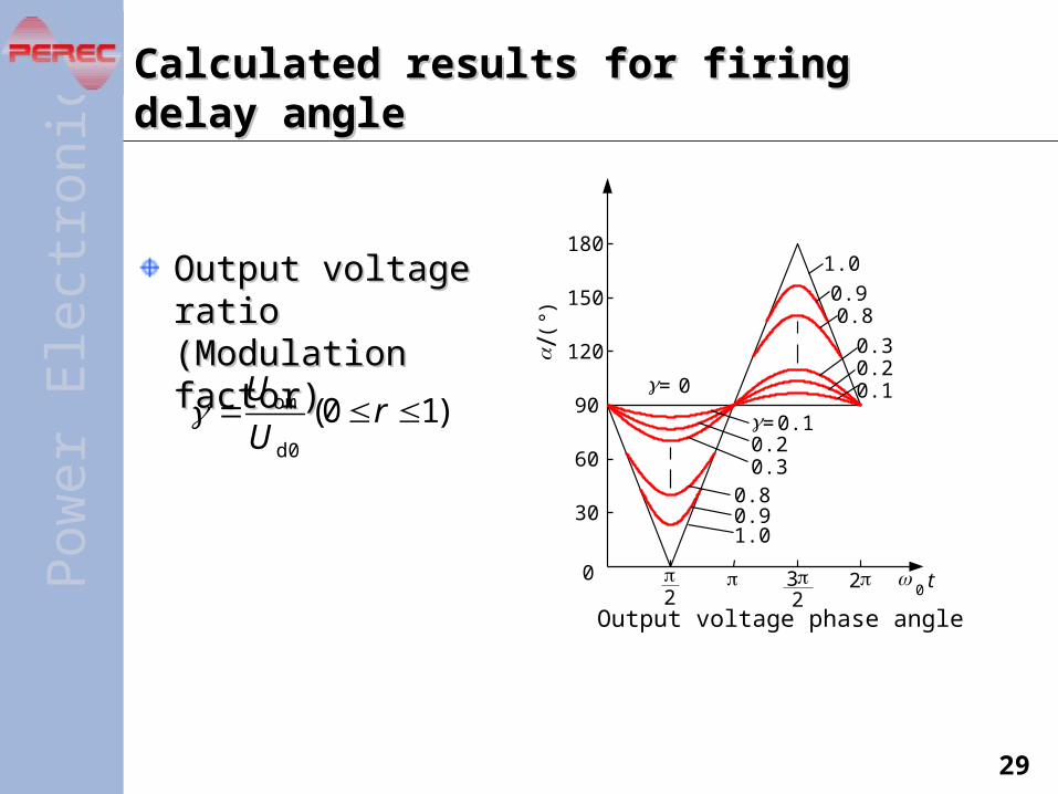
Calculated results for firing delay angleCalculated results for firing delay angle
Output voltage ratio Output voltage ratio (Modulation factor)(Modulation factor)
)10(d0
om rU
U = 0
= 0.1
/(
°)
Output voltage phase angle
0 t
120
150
180
30
60
90
0
0.10.20.3
0.80.9
1.0
0.8
0.20.3
0.91.0
22
23
Pow
erE
lec t
roni
cs
30
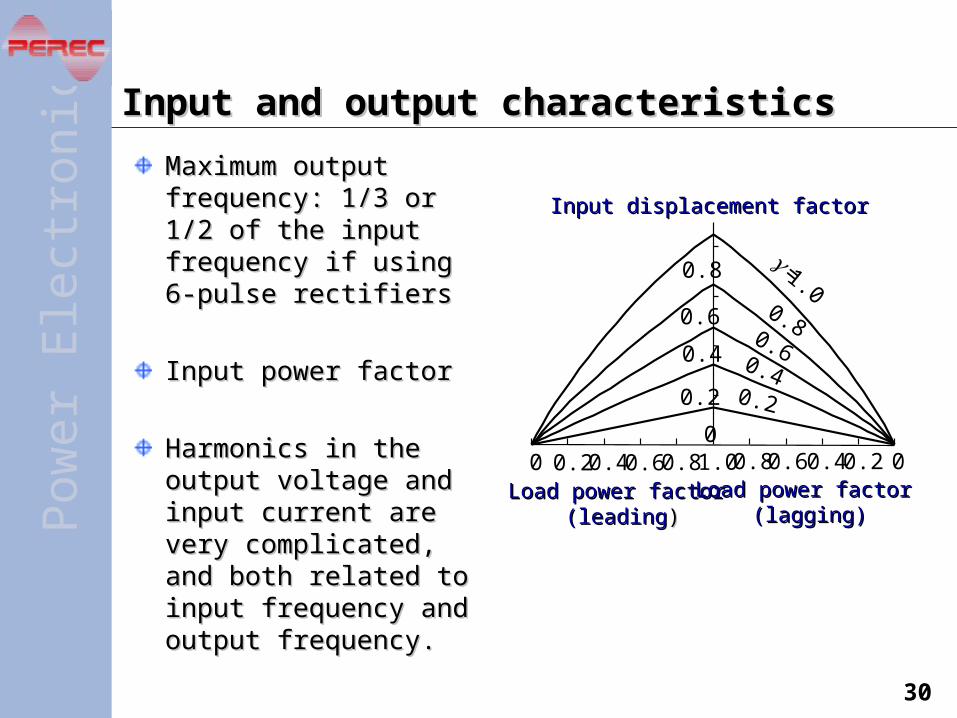
Input and output characteristicsInput and output characteristics
Maximum output Maximum output frequency: 1/3 or 1/2 of the frequency: 1/3 or 1/2 of the input frequency if using 6-input frequency if using 6-pulse rectifierspulse rectifiers
Input power factorInput power factor
Harmonics in the output Harmonics in the output voltage and input current voltage and input current are very complicated, and are very complicated, and both related to input both related to input frequency and output frequency and output frequency.frequency.
0.8 0.6 0.4 0.2 0
=1.0
Input displacement factorInput displacement factor
Load power factor Load power factor (lagging)(lagging)
Load power factorLoad power factor (leading (leading))
01.00.80.60.40.20
0.8
0.6
0.4
0.2
0.80.6
0.40.2
Pow
erE
lec t
roni
cs
31
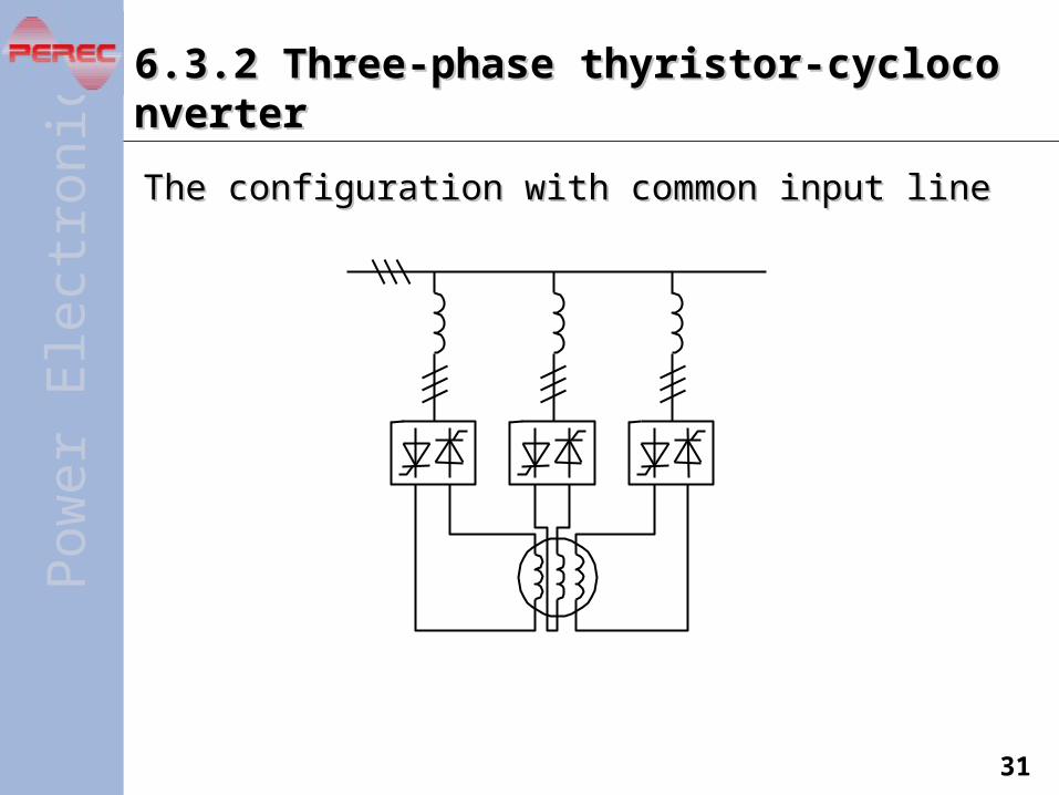
6.3.2 Three-phase thyristor-cycloconverter6.3.2 Three-phase thyristor-cycloconverter
The configuration with common input lineThe configuration with common input line
Pow
erE
lec t
roni
cs
32
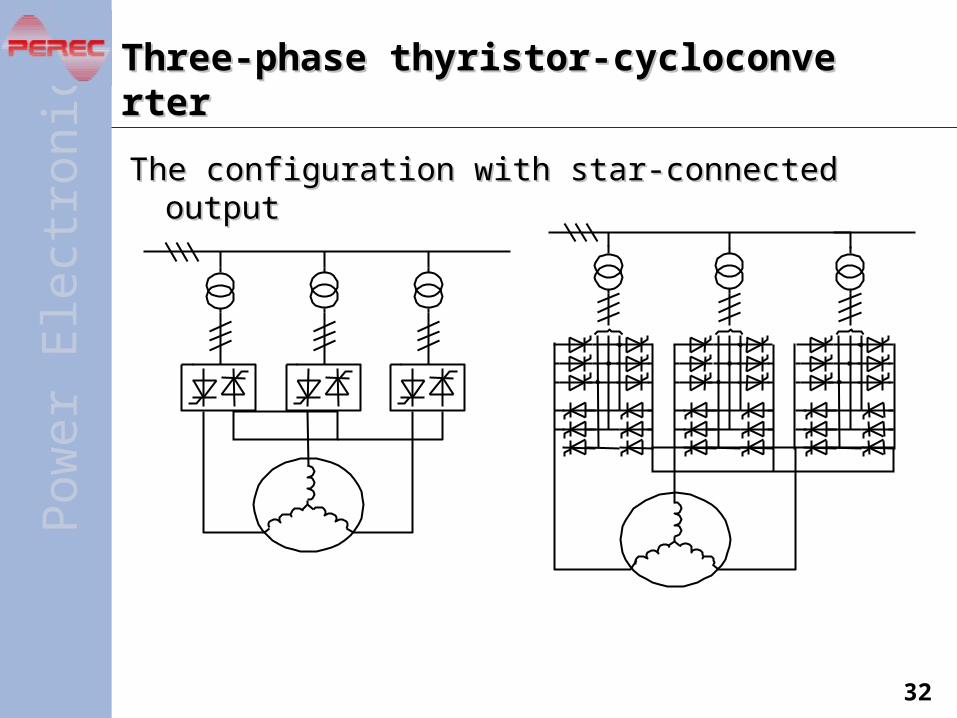
Three-phase thyristor-cycloconverterThree-phase thyristor-cycloconverter
The configuration with star-connected outputThe configuration with star-connected output
Pow
erE
lec t
roni
cs
33
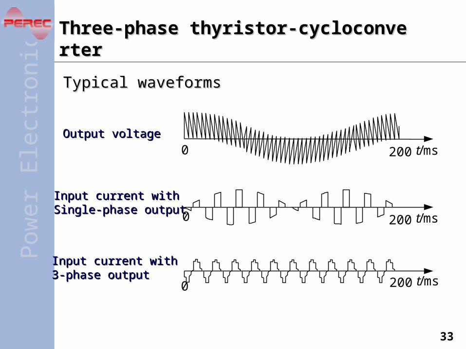
Three-phase thyristor-cycloconverterThree-phase thyristor-cycloconverter
Typical waveformsTypical waveforms
200 t/msOutput voltageOutput voltage
Input current withInput current with3-phase output 3-phase output
200 t/ms
200 t/ms
Input current withInput current withSingle-phase output Single-phase output
0
0
0

Pow
erE
lec t
roni
cs
34
Input and output characteristicsInput and output characteristicsThe maximum output frequency and the harmonics The maximum output frequency and the harmonics in the output voltage are the same as in single-in the output voltage are the same as in single-phase circuit.phase circuit.
Input power factor is a little higher than single-Input power factor is a little higher than single-phase circuit. phase circuit.
Harmonics in the input current is a little lower than Harmonics in the input current is a little lower than the single-phase circuit due to the cancellation of the single-phase circuit due to the cancellation of some harmonics among the 3 phases. some harmonics among the 3 phases.
To improve the input power factor:To improve the input power factor:– Use DC bias or 3k order component bias on each of the 3 Use DC bias or 3k order component bias on each of the 3
output phase voltagesoutput phase voltages

Pow
erE
lec t
roni
cs
35
Features and applicationsFeatures and applications
FeaturesFeatures– Direct frequency conversion—high efficiencyDirect frequency conversion—high efficiency– Bidirectional energy flow, easy to realize 4-quadrant Bidirectional energy flow, easy to realize 4-quadrant
operationoperation– Very complicated—too many power semiconductor Very complicated—too many power semiconductor
devicesdevices– Low output frequencyLow output frequency– Low input power factor and bad input current waveformLow input power factor and bad input current waveform
ApplicationsApplications– High power low speed AC motor driveHigh power low speed AC motor drive
Pow
erE
lec t
roni
cs
36
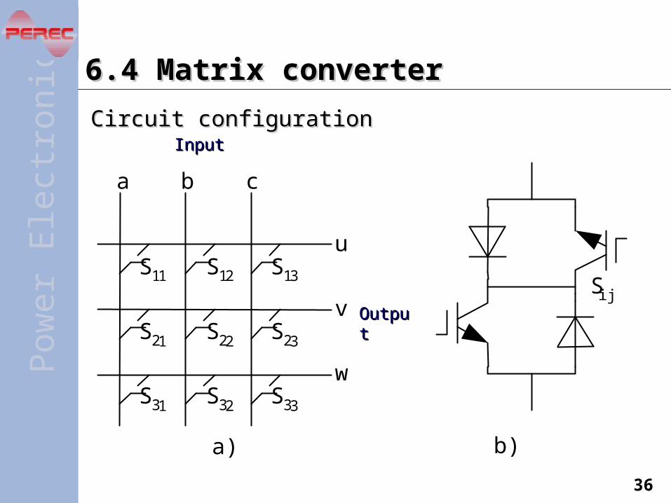
6.4 Matrix converter6.4 Matrix converter
Circuit configurationCircuit configuration
a) b)
InputInput
OutputOutput
a b c
u
v
w
S11 S12 S13
S21 S22 S23
S31 S32 S33
Sij
Pow
erE
lec t
roni
cs
37
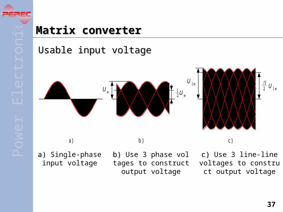
Matrix converterMatrix converter
Usable input voltageUsable input voltage
a ) b ) c )
U m
U 1 m U 1 m23
U m12
a) a) Single-phase input voltage
b) b) Use 3 phase voltages to construct output voltag
e
c) c) Use 3 line-line voltages to construct output voltag
e

Pow
erE
lec t
roni
cs
38
FeaturesFeatures
Direct frequency conversion—high efficiencyDirect frequency conversion—high efficiency
Can realize good input and output waveforms, low Can realize good input and output waveforms, low harmonics, and nearly unity displacement factorharmonics, and nearly unity displacement factor
Bidirectional energy flow, easy to realize 4-quadrant Bidirectional energy flow, easy to realize 4-quadrant operationoperation
Output frequency is not limited by input frequencyOutput frequency is not limited by input frequency
No need for bulk capacitor (as compared to indirect No need for bulk capacitor (as compared to indirect frequency converter)frequency converter)
Very complicated—too many power semiconductor Very complicated—too many power semiconductor devicesdevices
Output voltage magnitude is a little lower as Output voltage magnitude is a little lower as compared to indirect frequency converter.compared to indirect frequency converter.