Embed Size (px)
Citation preview
University of South CarolinaScholar Commons
Faculty Publications Electrical Engineering, Department of
1-1-2005
Power Enhancement of an Actively ControlledBattery/Ultracapacitor HybridLijun GaoBoeing, [email protected]
Roger A. DougalUniversity of South Carolina - Columbia, [email protected]
Shengyi LiuBoeing, [email protected]
Follow this and additional works at: https://scholarcommons.sc.edu/elct_facpub
Part of the Electrical and Computer Engineering Commons
This Article is brought to you by the Electrical Engineering, Department of at Scholar Commons. It has been accepted for inclusion in FacultyPublications by an authorized administrator of Scholar Commons. For more information, please contact [email protected].
Publication InfoPublished in IEEE Transactions on Power Electronics, Volume 20, 2005, pages 236-243.http://ieeexplore.ieee.org/xpl/RecentIssue.jsp?punumber=63© 2005 by IEEE
236 IEEE TRANSACTIONS ON POWER ELECTRONICS, VOL. 20, NO. 1, JANUARY 2005
Power Enhancement of an Actively ControlledBattery/Ultracapacitor Hybrid
Lijun Gao, Member, IEEE, Roger A. Dougal, Senior Member, IEEE, and Shengyi Liu, Senior Member, IEEE
Abstract—An actively controlled battery/ultracapacitor hybridhas broad applications in pulse-operated power systems. A con-verter is used to actively control the power flow from a battery, tocouple the battery to an ultracapacitor for power enhancement,and to deliver the power to a load efficiently. The experimental andsimulation results show that the hybrid can achieve much greaterspecific power while reducing battery current and its internalloss. A specific example of the hybrid built from two size 18650lithium-ion cells and two 100-F ultracapacitors achieved a peakpower of 132 W which is a three-times improvement in peak powercompared to the passive hybrid power source (hybrid without aconverter), and a seven times improvement as compared to thelithium-ion cells alone. The design presented here can be scaled tolarger or smaller power capacities for a variety of applications.
Index Terms—Hybrid power source, lithium-ion battery, peakpower enhancement, power converter, ultracapacitor.
I. INTRODUCTION
MANY classes of power systems, such as those in portableelectronic devices, telecommunication systems, space-
craft power systems, and electric vehicles, have a common char-acteristic in their load profiles. That is, they have a relatively lowaverage power requirement but a relatively high pulse power re-quirement. The typical pulse duration in these applications gen-erally ranges from hundreds of milliseconds to seconds, withpower levels depending on the applications. Battery/ultracapac-itor hybrid power sources can meet these pulse power require-ments with higher specific power and efficiency than batteriesalone.
An ultracapacitor, also referred to as a supercapacitor or anelectrochemical double layer capacitor [1], [2], stores charge ina double layer formed on a large surface area of micro-porousmaterial such as activated carbon. Generally, such devices havespecific energy in the range of 1 to 10 Wh/kg and high specificpower in the range of 1000 to 5000 W/kg. The charge/dischargeefficiency of ultracapacitors is very high, ranging from 85% to98%, and the rate of discharge can be fast, ranging from 0.3to 30 s. The lithium-ion rechargeable battery, in contrast, has ahigher specific energy in the range of 50 to 500 Wh/kg and alower specific power between 10 and 500 W/kg. Its charge/dis-charge efficiency is in the range of 75% to 90%, and the rateof discharge is typically between 0.3 and 3 h. A combination
Manuscript received September 17, 2003; revised July 13, 2004. This workwas supported by NRO under Contract NRO-00-C-1034, by ONR under Con-tract N00014-00-1-0368, and by ONR under Contract N00014-00-1-0131. Rec-ommended by Associate Editor K. Ngo.
The authors are with the Department of Electrical Engineering, University ofSouth Carolina, Columbia, SC 29208 USA (e-mail: [email protected]).
Digital Object Identifier 10.1109/TPEL.2004.839784
of battery and ultracapacitor can take advantage of each kind ofdevice to yield a power source of both high power density andhigh energy density.
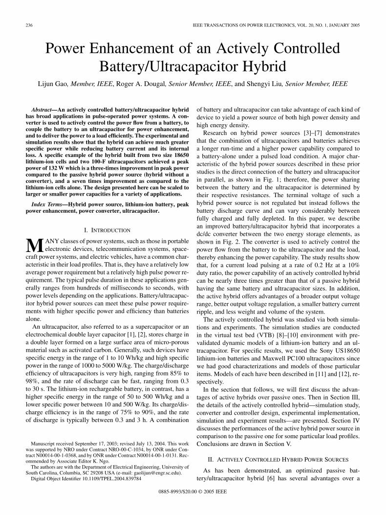
Research on hybrid power sources [3]–[7] demonstratesthat the combination of ultracapacitors and batteries achievesa longer run-time and a higher power capability compared toa battery-alone under a pulsed load condition. A major char-acteristic of the hybrid power sources described in these priorstudies is the direct connection of the battery and ultracapacitorin parallel, as shown in Fig. 1; therefore, the power sharingbetween the battery and the ultracapacitor is determined bytheir respective resistances. The terminal voltage of such ahybrid power source is not regulated but instead follows thebattery discharge curve and can vary considerably betweenfully charged and fully depleted. In this paper, we describean improved battery/ultracapacitor hybrid that incorporates adc/dc converter between the two energy storage elements, asshown in Fig. 2. The converter is used to actively control thepower flow from the battery to the ultracapacitor and the load,thereby enhancing the power capability. The study results showthat, for a current load pulsing at a rate of 0.2 Hz at a 10%duty ratio, the power capability of an actively controlled hybridcan be nearly three times greater than that of a passive hybridhaving the same battery and ultracapacitor sizes. In addition,the active hybrid offers advantages of a broader output voltagerange, better output voltage regulation, a smaller battery currentripple, and less weight and volume of the system.
The actively controlled hybrid was studied via both simula-tions and experiments. The simulation studies are conductedin the virtual test bed (VTB) [8]–[10] environment with pre-validated dynamic models of a lithium-ion battery and an ul-tracapacitor. For specific results, we used the Sony US18650lithium-ion batteries and Maxwell PC100 ultracapacitors sincewe had good characterizations and models of those particularitems. Models of each have been described in [11] and [12], re-spectively.
In the section that follows, we will first discuss the advan-tages of active hybrids over passive ones. Then in Section III,the details of the actively controlled hybrid—simulation study,converter and controller design, experimental implementation,simulation and experiment results—are presented. Section IVdiscusses the performances of the active hybrid power source incomparison to the passive one for some particular load profiles.Conclusions are drawn in Section V.
II. ACTIVELY CONTROLLED HYBRID POWER SOURCES
As has been demonstrated, an optimized passive bat-tery/ultracapacitor hybrid [6] has several advantages over a
0885-8993/$20.00 © 2005 IEEE
GAO et al.: POWER ENHANCEMENT OF AN ACTIVELY CONTROLLED BATTERY/ULTRACAPACITOR HYBRID 237
Fig. 1. VTB schematic of passive hybrid.
Fig. 2. Actively controlled battery/ultracapacitor hybrid.
battery-alone power source, such as higher peak power capa-bility, higher efficiency, and longer battery cycle life. However,the fact that the battery and ultracapacitor are directly con-nected limits the performance of this hybrid architecture. Firstof all, the ultracapacitor terminal voltage and the load voltageboth float with the battery terminal voltage (depending onstate of charge), which prevents the power capability of theultracapacitor from being fully exploited. For the same reason,the choice of the ultracapacitor array size is restricted by theterminal voltage of the battery since the upper limit of theultracapacitor voltage generally cannot be an arbitrary value.Secondly, the power enhancement of the passive hybrid sourceis limited by the partitioning of current between the batteryand the ultracapacitor, which is predominantly determined bythe equivalent series resistances of the two components. Thebattery current may have a large ripple during the pulse on-timeand the ripple reaches a maximum value at the end of the cur-rent pulse, which may result in shutting off any built-in batteryprotection circuit (common in lithium-ion batteries). Finally,the terminal voltage of the passive hybrid is not regulated, butinstead follows the discharge curve of the battery and can varyconsiderably between fully charged and fully depleted. Forexample, the terminal voltage of four lithium-ion cells in seriesmay drop 6.8 volts from fully charged to fully depleted (16.8 to10 V), equal to a voltage variation of 68% relative to the finalvoltage.
Adding a dc/dc converter between the battery and the ultraca-pacitor yields several advantages: 1) the ultracapacitor voltagecan be different from the battery voltage, which offers flexibilitywith respect to the design of the battery and ultracapacitor ar-rays, 2) the power capacity can be much higher than that of thepassive hybrid without exceeding the safety limit of the batterycurrent, 3) the power source terminal voltage can be kept rela-tively constant, with a smaller variation than that of the passivesource even as the battery is depleted, 4) the weight of the powersource for a given peak power can be smaller than that of a pas-sive power source for the same load, and 5) the dc/dc converter
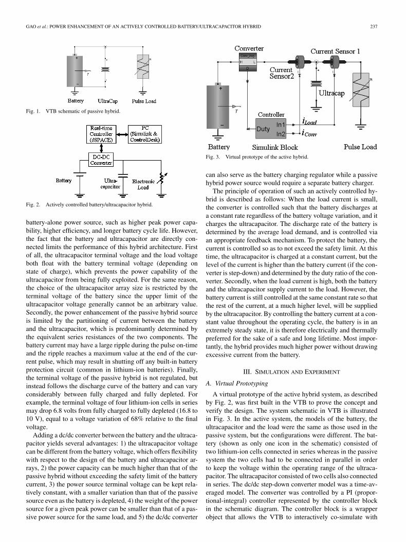
Fig. 3. Virtual prototype of the active hybrid.
can also serve as the battery charging regulator while a passivehybrid power source would require a separate battery charger.
The principle of operation of such an actively controlled hy-brid is described as follows: When the load current is small,the converter is controlled such that the battery discharges ata constant rate regardless of the battery voltage variation, and itcharges the ultracapacitor. The discharge rate of the battery isdetermined by the average load demand, and is controlled viaan appropriate feedback mechanism. To protect the battery, thecurrent is controlled so as to not exceed the safety limit. At thistime, the ultracapacitor is charged at a constant current, but thelevel of the current is higher than the battery current (if the con-verter is step-down) and determined by the duty ratio of the con-verter. Secondly, when the load current is high, both the batteryand the ultracapacitor supply current to the load. However, thebattery current is still controlled at the same constant rate so thatthe rest of the current, at a much higher level, will be suppliedby the ultracapacitor. By controlling the battery current at a con-stant value throughout the operating cycle, the battery is in anextremely steady state, it is therefore electrically and thermallypreferred for the sake of a safe and long lifetime. Most impor-tantly, the hybrid provides much higher power without drawingexcessive current from the battery.
III. SIMULATION AND EXPERIMENT
A. Virtual Prototyping
A virtual prototype of the active hybrid system, as describedby Fig. 2, was first built in the VTB to prove the concept andverify the design. The system schematic in VTB is illustratedin Fig. 3. In the active system, the models of the battery, theultracapacitor and the load were the same as those used in thepassive system, but the configurations were different. The bat-tery (shown as only one icon in the schematic) consisted oftwo lithium-ion cells connected in series whereas in the passivesystem the two cells had to be connected in parallel in orderto keep the voltage within the operating range of the ultraca-pacitor. The ultracapacitor consisted of two cells also connectedin series. The dc/dc step-down converter model was a time-av-eraged model. The converter was controlled by a PI (propor-tional-integral) controller represented by the controller blockin the schematic diagram. The controller block is a wrapperobject that allows the VTB to interactively co-simulate with
238 IEEE TRANSACTIONS ON POWER ELECTRONICS, VOL. 20, NO. 1, JANUARY 2005
Fig. 4. Control algorithm implemented in the Matlab/Simulink.
the controller that is defined in the Matlab/Simulink. The con-troller block had two input ports (In1 and In2) that were con-nected to two current sensors that monitored the load currentand the power converter output current, respectively. The mon-itored current signals were then fed to the PI controller; and thenew calculated converter duty ratio from the PI controller wassent back to the power converter model in the VTB through theoutput port (Duty).
The Simulink implementation of the PI controller is shown inFig. 4. The two input ports (In1 and In2) received the measuredcurrent signals and the output port (Duty) sent the new calcu-lated duty ratio to the power converter. The controller’s goalwas to keep the output current of the power converter at a rel-atively constant value equal to the load time-averaged current.This buffered the battery from high pulse currents, and main-tained a relatively constant ultracapacitor voltage. It can be seenin Fig. 4 that the load current received from input port In1 wasfirst integrated and then was averaged according to the currentsimulation time. After that, the calculated time-averaged loadcurrent was compared to the power converter output current re-ceived from input port In2 and the error between them was thenfed to the proportion-integrator. While it is obvious that moresophisticated control algorithms could be designed, this simplealgorithm is sufficient to demonstrate the essential capabilitiesof an actively controlled hybrid power source. The test showsthat this controller ensured zero steady-state error, and that theoutput of the hybrid power sources did follow the load demand.
B. Experimental Implementation
After the simulation study, the active hybrid power sourcewas built using real hardware. Fig. 5 shows a photograph of theexperimental setup, and Table I lists the parameters of the maincomponents. A dSPACE [13] real time controller controlled thedc/dc converter. Controller code was generated and compileddirectly from the Matlab/Simulink and then downloaded to thedSPACE hardware.
The pulse current demand was generated by an electronicload using the same pulse profile that was defined for the simula-tion experiment. The load was set to the external programmingmode with the pulse control signal coming from the dSPACEdigital output port. Experimental data was logged at 250 sam-ples/s. Fig. 6 shows the circuit diagram of the synchronous buckconverter. A voltage chopper consisting of a main switch and
Fig. 5. Experimental setup of the active hybrid system.
TABLE ISPECIFICATIONS OF THE ACTIVE HYBRID POWER SOURCE
Fig. 6. Circuit of the dc/dc converter.
a secondary switch (operating as a synchronous rectifier)converted the voltage from the battery pack to an appropriatelower voltage for the ultracapacitor. The component values ofthe converter are listed in Table I.
C. Operating Characteristics
The simulation and experimental results for the active hybridare presented in this section for an example case study of a pulsecurrent discharge of about 30 A, a pulse rate of 0.2 Hz, anda duty ratio of 10%. The current level was chosen so that thebattery current was below the safe limit. The load pulse dutyratio affects both the power enhancement and the efficiency fora given configuration of the battery and ultracapacitor arrays [6].Considering both power enhancement and efficiency, we chose0.1 as the duty ratio which yielded a pulse duration of 0.5 s.This duration falls within the range that interests us for mostpulsed-operations as discussed in the introduction.
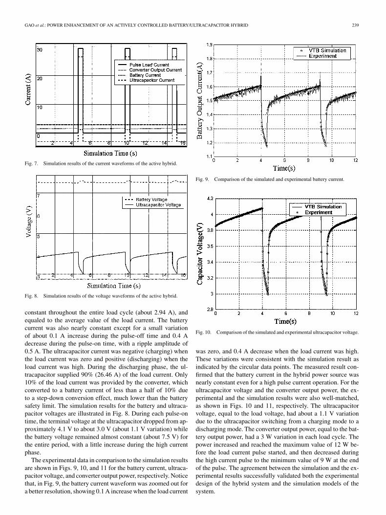
The electrical characteristics of the active power source pre-sented here include time-varying behaviors of the current, thevoltage, and the power. Fig. 7 shows the simulation results forthe current waveforms. The programmable load drew currentpulses as specified previously. The converter output current was
GAO et al.: POWER ENHANCEMENT OF AN ACTIVELY CONTROLLED BATTERY/ULTRACAPACITOR HYBRID 239
Fig. 7. Simulation results of the current waveforms of the active hybrid.
Fig. 8. Simulation results of the voltage waveforms of the active hybrid.
constant throughout the entire load cycle (about 2.94 A), andequaled to the average value of the load current. The batterycurrent was also nearly constant except for a small variationof about 0.1 A increase during the pulse-off time and 0.4 Adecrease during the pulse-on time, with a ripple amplitude of0.5 A. The ultracapacitor current was negative (charging) whenthe load current was zero and positive (discharging) when theload current was high. During the discharging phase, the ul-tracapacitor supplied 90% (26.46 A) of the load current. Only10% of the load current was provided by the converter, whichconverted to a battery current of less than a half of 10% dueto a step-down conversion effect, much lower than the batterysafety limit. The simulation results for the battery and ultraca-pacitor voltages are illustrated in Fig. 8. During each pulse-ontime, the terminal voltage at the ultracapacitor dropped from ap-proximately 4.1 V to about 3.0 V (about 1.1 V variation) whilethe battery voltage remained almost constant (about 7.5 V) forthe entire period, with a little increase during the high currentphase.
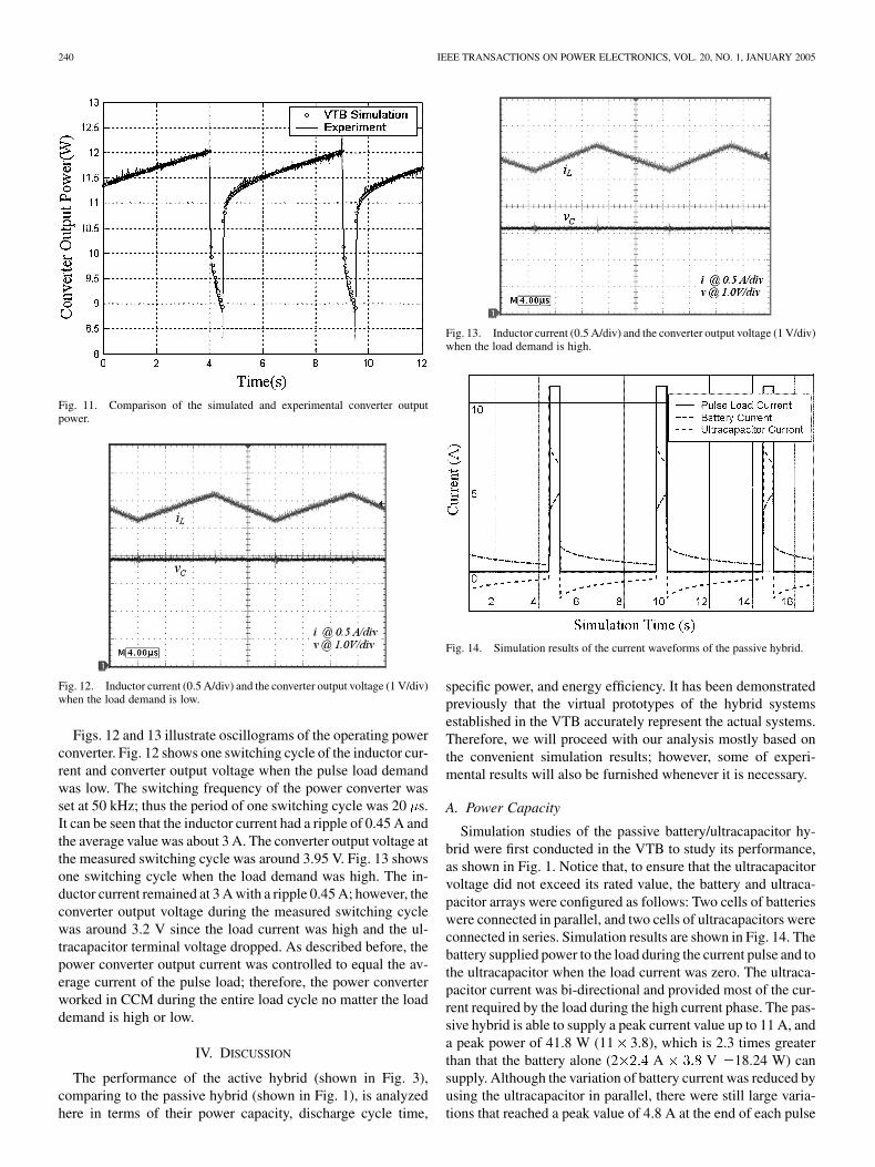
The experimental data in comparison to the simulation resultsare shown in Figs. 9, 10, and 11 for the battery current, ultraca-pacitor voltage, and converter output power, respectively. Noticethat, in Fig. 9, the battery current waveform was zoomed out fora better resolution, showing 0.1 A increase when the load current
Fig. 9. Comparison of the simulated and experimental battery current.
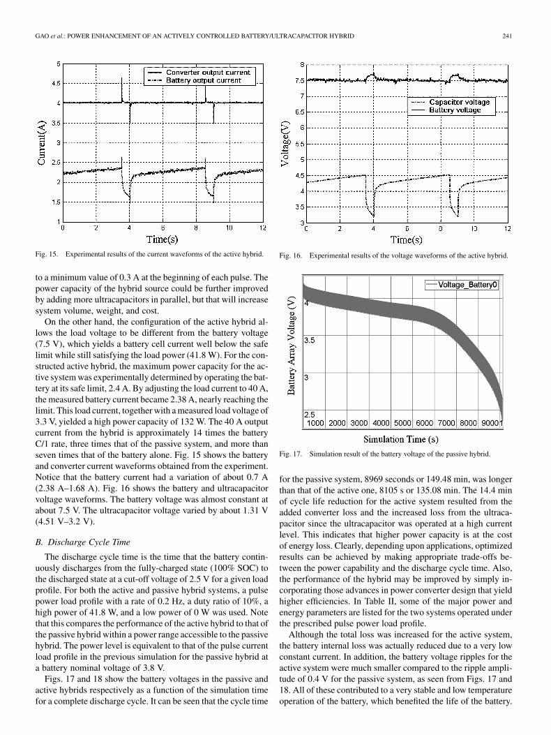
Fig. 10. Comparison of the simulated and experimental ultracapacitor voltage.
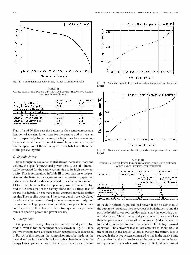
was zero, and 0.4 A decrease when the load current was high.These variations were consistent with the simulation result asindicated by the circular data points. The measured result con-firmed that the battery current in the hybrid power source wasnearly constant even for a high pulse current operation. For theultracapacitor voltage and the converter output power, the ex-perimental and the simulation results were also well-matched,as shown in Figs. 10 and 11, respectively. The ultracapacitorvoltage, equal to the load voltage, had about a 1.1 V variationdue to the ultracapacitor switching from a charging mode to adischarging mode. The converter output power, equal to the bat-tery output power, had a 3 W variation in each load cycle. Thepower increased and reached the maximum value of 12 W be-fore the load current pulse started, and then decreased duringthe high current pulse to the minimum value of 9 W at the endof the pulse. The agreement between the simulation and the ex-perimental results successfully validated both the experimentaldesign of the hybrid system and the simulation models of thesystem.
240 IEEE TRANSACTIONS ON POWER ELECTRONICS, VOL. 20, NO. 1, JANUARY 2005
Fig. 11. Comparison of the simulated and experimental converter outputpower.
Fig. 12. Inductor current (0.5 A/div) and the converter output voltage (1 V/div)when the load demand is low.
Figs. 12 and 13 illustrate oscillograms of the operating powerconverter. Fig. 12 shows one switching cycle of the inductor cur-rent and converter output voltage when the pulse load demandwas low. The switching frequency of the power converter wasset at 50 kHz; thus the period of one switching cycle was 20 s.It can be seen that the inductor current had a ripple of 0.45 A andthe average value was about 3 A. The converter output voltage atthe measured switching cycle was around 3.95 V. Fig. 13 showsone switching cycle when the load demand was high. The in-ductor current remained at 3 A with a ripple 0.45 A; however, theconverter output voltage during the measured switching cyclewas around 3.2 V since the load current was high and the ul-tracapacitor terminal voltage dropped. As described before, thepower converter output current was controlled to equal the av-erage current of the pulse load; therefore, the power converterworked in CCM during the entire load cycle no matter the loaddemand is high or low.
IV. DISCUSSION
The performance of the active hybrid (shown in Fig. 3),comparing to the passive hybrid (shown in Fig. 1), is analyzedhere in terms of their power capacity, discharge cycle time,
Fig. 13. Inductor current (0.5 A/div) and the converter output voltage (1 V/div)when the load demand is high.
Fig. 14. Simulation results of the current waveforms of the passive hybrid.
specific power, and energy efficiency. It has been demonstratedpreviously that the virtual prototypes of the hybrid systemsestablished in the VTB accurately represent the actual systems.Therefore, we will proceed with our analysis mostly based onthe convenient simulation results; however, some of experi-mental results will also be furnished whenever it is necessary.
A. Power Capacity
Simulation studies of the passive battery/ultracapacitor hy-brid were first conducted in the VTB to study its performance,as shown in Fig. 1. Notice that, to ensure that the ultracapacitorvoltage did not exceed its rated value, the battery and ultraca-pacitor arrays were configured as follows: Two cells of batterieswere connected in parallel, and two cells of ultracapacitors wereconnected in series. Simulation results are shown in Fig. 14. Thebattery supplied power to the load during the current pulse and tothe ultracapacitor when the load current was zero. The ultraca-pacitor current was bi-directional and provided most of the cur-rent required by the load during the high current phase. The pas-sive hybrid is able to supply a peak current value up to 11 A, anda peak power of 41.8 W (11 3.8), which is 2.3 times greaterthan that the battery alone (2 A V 18.24 W) cansupply. Although the variation of battery current was reduced byusing the ultracapacitor in parallel, there were still large varia-tions that reached a peak value of 4.8 A at the end of each pulse
GAO et al.: POWER ENHANCEMENT OF AN ACTIVELY CONTROLLED BATTERY/ULTRACAPACITOR HYBRID 241
Fig. 15. Experimental results of the current waveforms of the active hybrid.
to a minimum value of 0.3 A at the beginning of each pulse. Thepower capacity of the hybrid source could be further improvedby adding more ultracapacitors in parallel, but that will increasesystem volume, weight, and cost.
On the other hand, the configuration of the active hybrid al-lows the load voltage to be different from the battery voltage(7.5 V), which yields a battery cell current well below the safelimit while still satisfying the load power (41.8 W). For the con-structed active hybrid, the maximum power capacity for the ac-tive system was experimentally determined by operating the bat-tery at its safe limit, 2.4 A. By adjusting the load current to 40 A,the measured battery current became 2.38 A, nearly reaching thelimit. This load current, together with a measured load voltage of3.3 V, yielded a high power capacity of 132 W. The 40 A outputcurrent from the hybrid is approximately 14 times the batteryC/1 rate, three times that of the passive system, and more thanseven times that of the battery alone. Fig. 15 shows the batteryand converter current waveforms obtained from the experiment.Notice that the battery current had a variation of about 0.7 A(2.38 A–1.68 A). Fig. 16 shows the battery and ultracapacitorvoltage waveforms. The battery voltage was almost constant atabout 7.5 V. The ultracapacitor voltage varied by about 1.31 V(4.51 V–3.2 V).
B. Discharge Cycle Time
The discharge cycle time is the time that the battery contin-uously discharges from the fully-charged state (100% SOC) tothe discharged state at a cut-off voltage of 2.5 V for a given loadprofile. For both the active and passive hybrid systems, a pulsepower load profile with a rate of 0.2 Hz, a duty ratio of 10%, ahigh power of 41.8 W, and a low power of 0 W was used. Notethat this compares the performance of the active hybrid to that ofthe passive hybrid within a power range accessible to the passivehybrid. The power level is equivalent to that of the pulse currentload profile in the previous simulation for the passive hybrid ata battery nominal voltage of 3.8 V.
Figs. 17 and 18 show the battery voltages in the passive andactive hybrids respectively as a function of the simulation timefor a complete discharge cycle. It can be seen that the cycle time
Fig. 16. Experimental results of the voltage waveforms of the active hybrid.
Fig. 17. Simulation result of the battery voltage of the passive hybrid.
for the passive system, 8969 seconds or 149.48 min, was longerthan that of the active one, 8105 s or 135.08 min. The 14.4 minof cycle life reduction for the active system resulted from theadded converter loss and the increased loss from the ultraca-pacitor since the ultracapacitor was operated at a high currentlevel. This indicates that higher power capacity is at the costof energy loss. Clearly, depending upon applications, optimizedresults can be achieved by making appropriate trade-offs be-tween the power capability and the discharge cycle time. Also,the performance of the hybrid may be improved by simply in-corporating those advances in power converter design that yieldhigher efficiencies. In Table II, some of the major power andenergy parameters are listed for the two systems operated underthe prescribed pulse power load profile.
Although the total loss was increased for the active system,the battery internal loss was actually reduced due to a very lowconstant current. In addition, the battery voltage ripples for theactive system were much smaller compared to the ripple ampli-tude of 0.4 V for the passive system, as seen from Figs. 17 and18. All of these contributed to a very stable and low temperatureoperation of the battery, which benefited the life of the battery.
242 IEEE TRANSACTIONS ON POWER ELECTRONICS, VOL. 20, NO. 1, JANUARY 2005
Fig. 18. Simulation result of the battery voltage of the active hybrid.
TABLE IICOMPARISON OF THE ENERGY DISTRIBUTION BETWEEN THE PASSIVE HYBRID
AND THE ACTIVE HYBRID
Figs. 19 and 20 illustrate the battery surface temperatures as afunction of the simulation time for the passive and active sys-tems, respectively. In both cases, the battery surface was set upfor a heat transfer coefficient of 4 W/m K. As can be seen, thefinal temperature of the active system was 6-K lower than thatof the passive hybrid.
C. Specific Power
Even though the converter contributes an increase in mass andvolume, the specific power and power density are still dramat-ically increased for the active system due to its high power ca-pacity. This is summarized in Table III in comparison to the pas-sive and the battery-alone systems for the previously specifiedpulse current load condition (a period of 5 s and a duty ratio of10%). It can be seen that the specific power of the active hy-brid is 3.2 times that of the battery alone and 2.7 times that ofthe passive hybrid. The power density comparison yields similarresults. The specific power and the power density are calculatedbased on the parameters of major power components only, andthe system packaging and some auxiliary components are notconsidered here. It is clear that the active system is superior interms of specific power and power density.
D. Energy Loss
Comparison of energy losses for the active and passive hy-brids as well as for their components is shown in Fig. 21. Sincethe two systems have different power capabilities, as discussedin Part A of this section, the comparison must be made on thenormalized basis, for which the loss is given here in terms of theenergy loss in joules per joule of energy delivered as a function
Fig. 19. Simulation result of the battery surface temperature of the passivehybrid.
Fig. 20. Simulation result of the battery surface temperature of the activehybrid.
TABLE IIICOMPARISON OF THE POWER CAPABILITY AMONG THREE KINDS OF POWER
SOURCE UNDER SPECIFIED TEST CONDITION
of the duty ratio of the pulsed load power. It can be seen that, asthe duty ratio increases, the energy loss in both the active and thepassive hybrid power sources decreases since the operating cur-rent decreases. The active hybrid yields more total energy lossthan the passive one because of two reasons: 1) added converterloss and 2) increased loss of ultracapacitor due to high currentoperation. The converter loss in fact amounts to about 50% ofthe total loss in the active system. However, the battery loss isreduced in the active system compared to that in the passive one.Also notice that the battery loss and the converter loss in the ac-tive system remain nearly constant as a result of battery constant
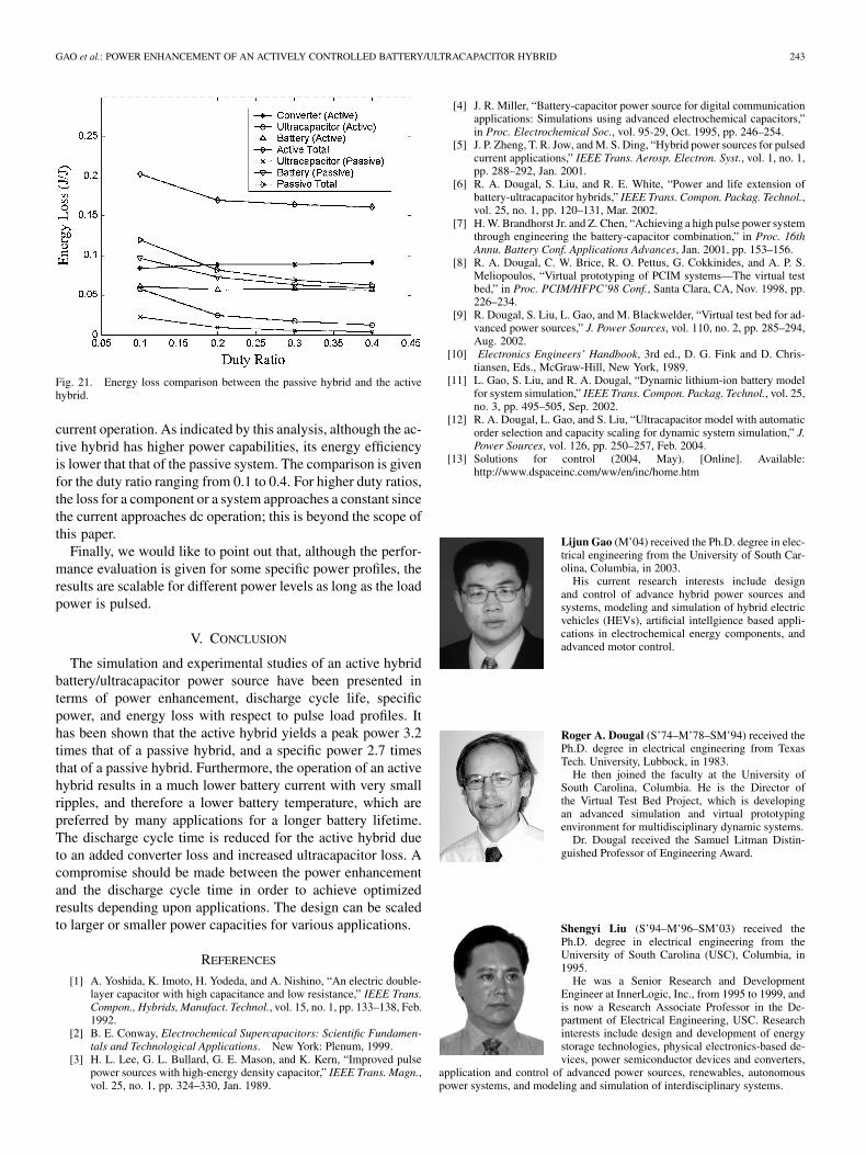
GAO et al.: POWER ENHANCEMENT OF AN ACTIVELY CONTROLLED BATTERY/ULTRACAPACITOR HYBRID 243
Fig. 21. Energy loss comparison between the passive hybrid and the activehybrid.
current operation. As indicated by this analysis, although the ac-tive hybrid has higher power capabilities, its energy efficiencyis lower that that of the passive system. The comparison is givenfor the duty ratio ranging from 0.1 to 0.4. For higher duty ratios,the loss for a component or a system approaches a constant sincethe current approaches dc operation; this is beyond the scope ofthis paper.
Finally, we would like to point out that, although the perfor-mance evaluation is given for some specific power profiles, theresults are scalable for different power levels as long as the loadpower is pulsed.
V. CONCLUSION
The simulation and experimental studies of an active hybridbattery/ultracapacitor power source have been presented interms of power enhancement, discharge cycle life, specificpower, and energy loss with respect to pulse load profiles. Ithas been shown that the active hybrid yields a peak power 3.2times that of a passive hybrid, and a specific power 2.7 timesthat of a passive hybrid. Furthermore, the operation of an activehybrid results in a much lower battery current with very smallripples, and therefore a lower battery temperature, which arepreferred by many applications for a longer battery lifetime.The discharge cycle time is reduced for the active hybrid dueto an added converter loss and increased ultracapacitor loss. Acompromise should be made between the power enhancementand the discharge cycle time in order to achieve optimizedresults depending upon applications. The design can be scaledto larger or smaller power capacities for various applications.
REFERENCES
[1] A. Yoshida, K. Imoto, H. Yodeda, and A. Nishino, “An electric double-layer capacitor with high capacitance and low resistance,” IEEE Trans.Compon., Hybrids, Manufact. Technol., vol. 15, no. 1, pp. 133–138, Feb.1992.
[2] B. E. Conway, Electrochemical Supercapacitors: Scientific Fundamen-tals and Technological Applications. New York: Plenum, 1999.
[3] H. L. Lee, G. L. Bullard, G. E. Mason, and K. Kern, “Improved pulsepower sources with high-energy density capacitor,” IEEE Trans. Magn.,vol. 25, no. 1, pp. 324–330, Jan. 1989.
[4] J. R. Miller, “Battery-capacitor power source for digital communicationapplications: Simulations using advanced electrochemical capacitors,”in Proc. Electrochemical Soc., vol. 95-29, Oct. 1995, pp. 246–254.
[5] J. P. Zheng, T. R. Jow, and M. S. Ding, “Hybrid power sources for pulsedcurrent applications,” IEEE Trans. Aerosp. Electron. Syst., vol. 1, no. 1,pp. 288–292, Jan. 2001.
[6] R. A. Dougal, S. Liu, and R. E. White, “Power and life extension ofbattery-ultracapacitor hybrids,” IEEE Trans. Compon. Packag. Technol.,vol. 25, no. 1, pp. 120–131, Mar. 2002.
[7] H. W. Brandhorst Jr. and Z. Chen, “Achieving a high pulse power systemthrough engineering the battery-capacitor combination,” in Proc. 16thAnnu. Battery Conf. Applications Advances, Jan. 2001, pp. 153–156.
[8] R. A. Dougal, C. W. Brice, R. O. Pettus, G. Cokkinides, and A. P. S.Meliopoulos, “Virtual prototyping of PCIM systems—The virtual testbed,” in Proc. PCIM/HFPC’98 Conf., Santa Clara, CA, Nov. 1998, pp.226–234.
[9] R. Dougal, S. Liu, L. Gao, and M. Blackwelder, “Virtual test bed for ad-vanced power sources,” J. Power Sources, vol. 110, no. 2, pp. 285–294,Aug. 2002.
[10] Electronics Engineers’ Handbook, 3rd ed., D. G. Fink and D. Chris-tiansen, Eds., McGraw-Hill, New York, 1989.
[11] L. Gao, S. Liu, and R. A. Dougal, “Dynamic lithium-ion battery modelfor system simulation,” IEEE Trans. Compon. Packag. Technol., vol. 25,no. 3, pp. 495–505, Sep. 2002.
[12] R. A. Dougal, L. Gao, and S. Liu, “Ultracapacitor model with automaticorder selection and capacity scaling for dynamic system simulation,” J.Power Sources, vol. 126, pp. 250–257, Feb. 2004.
[13] Solutions for control (2004, May). [Online]. Available:http://www.dspaceinc.com/ww/en/inc/home.htm
Lijun Gao (M’04) received the Ph.D. degree in elec-trical engineering from the University of South Car-olina, Columbia, in 2003.
His current research interests include designand control of advance hybrid power sources andsystems, modeling and simulation of hybrid electricvehicles (HEVs), artificial intellgience based appli-cations in electrochemical energy components, andadvanced motor control.
Roger A. Dougal (S’74–M’78–SM’94) received thePh.D. degree in electrical engineering from TexasTech. University, Lubbock, in 1983.
He then joined the faculty at the University ofSouth Carolina, Columbia. He is the Director ofthe Virtual Test Bed Project, which is developingan advanced simulation and virtual prototypingenvironment for multidisciplinary dynamic systems.
Dr. Dougal received the Samuel Litman Distin-guished Professor of Engineering Award.
Shengyi Liu (S’94–M’96–SM’03) received thePh.D. degree in electrical engineering from theUniversity of South Carolina (USC), Columbia, in1995.
He was a Senior Research and DevelopmentEngineer at InnerLogic, Inc., from 1995 to 1999, andis now a Research Associate Professor in the De-partment of Electrical Engineering, USC. Researchinterests include design and development of energystorage technologies, physical electronics-based de-vices, power semiconductor devices and converters,
application and control of advanced power sources, renewables, autonomouspower systems, and modeling and simulation of interdisciplinary systems.


![Transient Enhancement of Smart Grid Using SMES Controlled ...article.easjournal.net/pdf/10.11648.j.eas.20200503.12.pdf · rapid changes in energy demands [3]. Several traditional](https://img.pdfslide.net/doc/110x75/6077205b4557ae566e2c1294/transient-enhancement-of-smart-grid-using-smes-controlled-rapid-changes-in-energy.jpg)