Embed Size (px)
Citation preview
Power Factor Correction Focusing on Magnetic
Coupling of Parallel-connected Wires for Inductive
Power Transfer System
Keita Furukawa, Keisuke Kusaka, Jun-ichi Itoh
Nagaoka University of Technology
Department of Electrical, Electronics and Information
Nagaoka, Niigata, Japan
[email protected], [email protected], [email protected]
Abstract— This paper proposes a power factor correction
method of a non-resonant IPT system using a four-winding
transformer. The proposed technique is applied to the IPT
system with a dual active bridge converter to reduce conduction
loss and winding loss. When two pairs of the primary-side and
the secondary-side wires are connected in parallel, the low
coupling coefficient between the wires driven by in-phase voltage
corrects the power factor from the viewpoint of the power supply
due to the improvement of an equivalent magnetic coupling. The
effect of the power factor correction is assessed by experiments
with two four-winding transformers, coupling coefficient of
which is different from each other. As experimental results, it is
confirmed that a maximum efficiency with the lower coupling
coefficient between the parallel connected wires is improved by
3.0% in comparison with the system, which has the high coupling
coefficient.
Keywords—wireless power transfer; multi-winding
transformer; non-resonant inductive power transfer; dual active
bridge
I. INTRODUCTION
In recent years, inductive power transfer (IPT) systems have
attracted many researchers as a safety and convenient battery
chargers for electrical vehicles (EVs) [1-6]. The IPT systems
are able to achieve power transmission without electrical
contacts. An increase in a transmission distance of
transmission coils causes a reduction of mutual inductance,
which results in a low power factor from the view of power
supply because the reactive current increases [7]. Large
reactive current is one of the factors reducing system
efficiency.
In order to correct the power factor, the IPT systems using
resonance phenomena have been proposed [1-6][8]. Resonant
capacitors are connected in series or parallel to the
transmission coils in order to compensate the reactance of the
coils by LC resonance [1-6]. Therefore, the resonant IPT
systems can achieve unity power factor at the resonance
frequency because reactive current is canceled. Considering
with actual high-power applications, however, position
misalignment of coils or tolerance of resonant component
degrades the transmission efficiency because the resonant
frequency does not match an operation frequency [1], [6]. In
particular, capacitive load increases switching loss of a
primary-side inverter because ZVS (zero voltage switching)
and ZCS (zero current switching) are not achieved [8].
In order to solve the above-mentioned problems of the
resonant IPT system, the non-resonant IPT system utilizing a
dual active bridge (DAB) converter has been proposed [9]. In
the system, the transmission power is determined by a phase
difference between the inverter output voltages of the primary
side and the secondary side. This method achieves the power
factor correction without resonant capacitors [8]. Besides,
ZVS is achieved at all switching devices despite load
conditions [9]-[10]. However, high reactive current still leads
to the increase in a conduction loss of the switching devices
and the winding loss of the transmission coils due to low
magnetic coupling [10]. Thus the non-resonant IPT system has
to achieve the reduction of the conduction loss and the
winding loss when the system is employed to lower-magnetic
coupling applications. This paper proposes a power-factor-correction method for
non-resonant IPT systems with a multi-winding transformer as one of the solution to overcome issues of the high conduction loss and winding loss. Two or more wires are connected to the primary core and the secondary core in parallel. From the equivalent circuit of the systems, the weak coupling coefficient kc between the parallel-connected wires decreases equivalent leakage inductance. Thus a low-kc transformer reduces the reactive current at the same load.
This paper is organized as follows; first, the theoretical expressions of output power and the power factor is derived. Then, the comparative testing results are showed with a 1.1-kW prototype using two multi-winding transformers which have different coupling kc: the conventional high-kc transformer and the proposed low-kc transformer. As a result, power-factor correction and reduction of input current are achieved in the proposed transformer. Moreover, the maximum system
efficiency of the prototype circuit is improved from 87.3% to 90.3% with the proposed transformer.
II. CONVENTIONAL METHODS OF IPT SYSTEMS
A. Conventional Resonant Inductive Power Transfer System
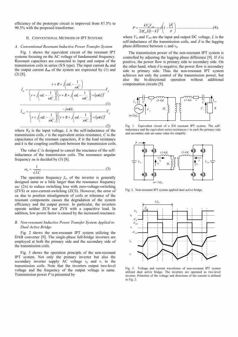
Fig. 1 shows the equivalent circuit of the resonant IPT systems focusing on the AC voltage of fundamental frequency. Resonant capacitors are connected to input and output of the transmission coils in series (S/S type). The input current Iin and the output current Iout of the system are expressed by (1) and (2) [8].
pin V
kLC
LjRrC
Ljr
CLjRr
I 211
1
.................................................................................... (1)
pout V
kLC
LjRrC
Ljr
kLjI
211
.................................................................................... (2) where Vp is the input voltage, L is the self-inductance of the transmission coils, r is the equivalent series resistance, C is the capacitance of the resonant capacitors, R is the load resistance and k is the coupling coefficient between the transmission coils.
The value C is designed to cancel the reactance of the self-inductance of the transmission coils. The resonance angular
frequency is decided by (3) [8].
LC
10 .............................................................. (3)
The operation frequency fsw of the inverter is generally designed same or a little larger than the resonance frequency
/ (2) to reduce switching loss with zero-voltage-switching (ZVS) or zero-current-switching (ZCS). However, the error of
due to position misalignment of coils or tolerance of the resonant components causes the degradation of the system efficiency and the output power. In particular, the inverters operate neither ZCS nor ZVS with a capacitive load. In addition, low power factor is caused by the increased reactance.
B. Non-resonant Inductive Power Transfer System Applied to
Dual Active Bridge
Fig. 2 shows the non-resonant IPT system utilizing the DAB converter [9]. The single-phase full-bridge inverters are employed at both the primary side and the secondary side of the transmission coils.
Fig. 3 shows the operation principle of the non-resonant IPT system. Not only the primary inverter but also the secondary inverter supply AC voltage vp and vs to the transmission coils. Note that the inverters output two-level voltage and the frequency of the output voltage is same. Transmission power P is presented by
2
12 kLf
VkVP
sw
outin .................................... (4),
where Vin and Vout are the input and output DC voltage, L is the
self-inductance of the transmission coils, and is the lagging phase difference between vs and vp.
The transmission power of the non-resonant IPT system is
controlled by adjusting the lagging phase difference [9]. If is positive, the power flow is primary side to secondary side. On
the other hand, when is negative, the power flow is secondary side to primary side. Thus the non-resonant IPT system achieves not only the control of the transmission power, but also the bi-directional operation without additional compensation circuits [9].
kL R
(1-k)L (1-k)L
pV
2fsw
inI
sV
C C outIrr
Fig. 1. Equivalent circuit of a S/S resonant IPT system. The self-
inductance and the equivalent series resistances r in each the primary side
and secondary side are same value for simplify.
Vin vp
ip
kL
(1-k)L (1-k)L
P
Vout
=2fsw
vs
is
Fig. 2. Non-resonant IPT system applied dual active bridge.
1/fsw
vp
Vin
ip
-Vin
-Vout
Vout
vs
is
Fig. 3. Voltage and current waveforms of non-resonant IPT system utilized dual active bridge. The inverters are operated as two-level
inverter. Polarities of the voltage and directions of the current is defined
in Fig. 2.
+ +Vin Vout
kM
kc kc
kDAB
kM
vp vs
Ip_rms,ip
Pp
Is_rms,is
PsFour-winding transformer
cosqin
P’
Cin Cout
LoutLin
S1
S2
S3
S4
S5
S6
S7
S8
Winding 1
Winding 2
Winding 3
Winding 4
i1v1
i2v2
i3v3
i4v4
iout
LDAB
LDAB LDAB
LDAB
Primary side Secandary side
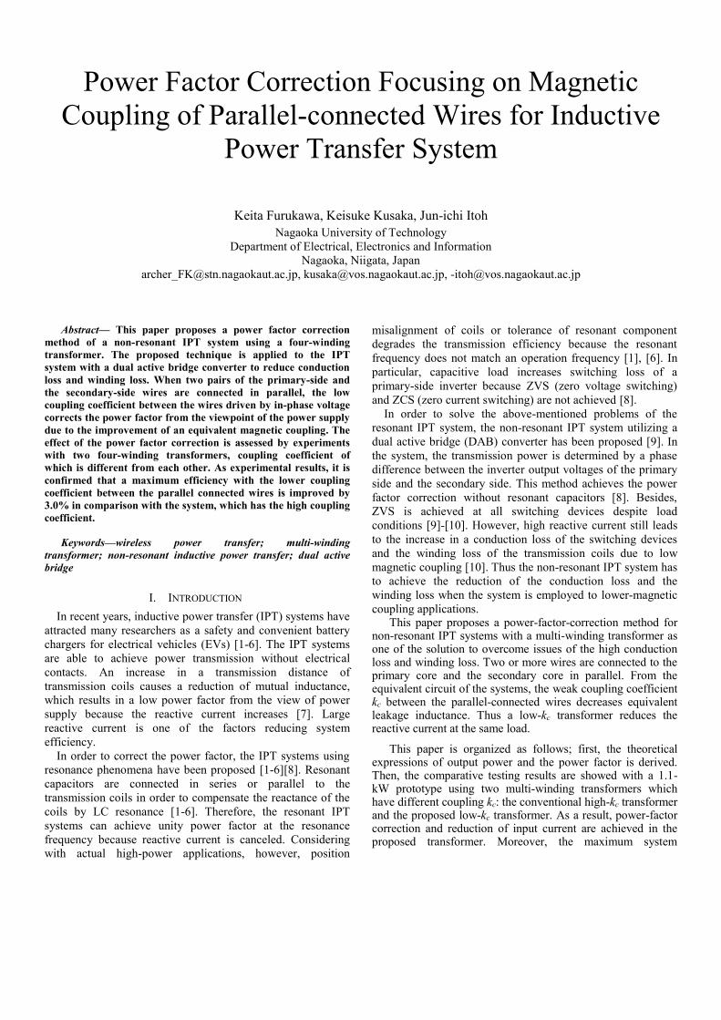
Fig. 4. Circuit configuration of proposed IPT system using four-winding transformer. The cores of the four-winding transformer is shared in each the primary
side and the secondary side. The output power Pout is defined as lower value of |Pp| or |Ps|.
The total power factor from the view point of the inverter is always lower than 1, because the excitation current flows for
the small mutual inductance regardless of [9] [10]. In particular, when the coupling coefficient k is significantly low (k = 0.01–0.2), the power factor is greatly decreased because of the large excitation current. The increase in the excitation current causes large conduction loss and copper loss. Therefore, it is important to keep the coupling coefficient as high as possible. In the next section, the proposed power-factor-correction method with a four-winding transformer is described.
III. PROPOSED CIRCUIT CONFIGURATION
A. System Configuration
Fig. 4 shows the system configuration of the proposed
system. The difference of the proposed system compared with
the conventional non-resonant IPT system (Fig. 2) is that the
four-winding transformer is introduced as the transmission
coils. Two primary side wires are wound onto one shared
primary core. The same procedure is carried out at the
secondary side. Through this winding structure, the windings
on each side are magnetically coupled with the coupling
coefficient kc. Considering the reduction of power loss in the converter,
the multiple single-phase full-bridge inverters should be connected to the each winding. Besides, each of the primary-side inverters and the secondary-side inverters is driven in phase to avoid cross currents. However, only one DAB converter drives the four-winding transformer in this experiment for the simplicity. A parallel connection of the full-bridge inverter is more effective to decrease the conduction loss of MOSFETs because the current is divided into each converter. In next section, a method of increasing an equivalent magnetic coupling between the primary side and the secondary side is discussed.
B. Analysis of Four-winding Transformers
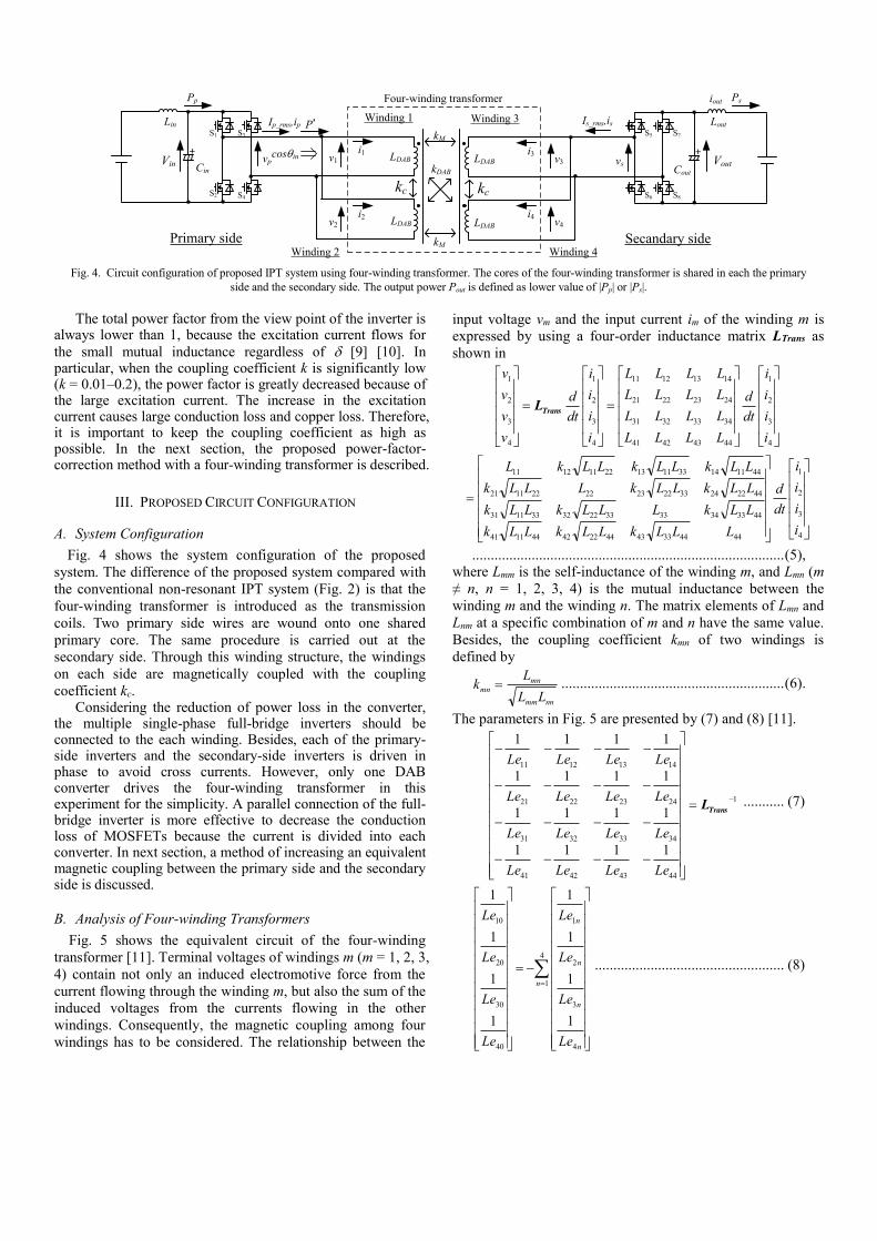
Fig. 5 shows the equivalent circuit of the four-winding
transformer [11]. Terminal voltages of windings m (m = 1, 2, 3,
4) contain not only an induced electromotive force from the
current flowing through the winding m, but also the sum of the
induced voltages from the currents flowing in the other
windings. Consequently, the magnetic coupling among four
windings has to be considered. The relationship between the
input voltage vm and the input current im of the winding m is
expressed by using a four-order inductance matrix LTrans as
shown in
4
3
2
1
44434241
34333231
24232221
14131211
4
3
2
1
4
3
2
1
i
i
i
i
dt
d
LLLL
LLLL
LLLL
LLLL
i
i
i
i
dt
d
v
v
v
v
TransL
4
3
2
1
44443343442242441141
44333433332232331131
44222433222322221121
44111433111322111211
i
i
i
i
dt
d
LLLkLLkLLk
LLkLLLkLLk
LLkLLkLLLk
LLkLLkLLkL
.................................................................................... (5),
where Lmm is the self-inductance of the winding m, and Lmn (m
≠ n, n = 1, 2, 3, 4) is the mutual inductance between the
winding m and the winding n. The matrix elements of Lmn and
Lnm at a specific combination of m and n have the same value.
Besides, the coupling coefficient kmn of two windings is
defined by
nnmm
mnmn
LL
Lk ............................................................ (6).
The parameters in Fig. 5 are presented by (7) and (8) [11].
1
44434241
34333231
24232221
14131211
1111
1111
1111
1111
TransL
LeLeLeLe
LeLeLeLe
LeLeLeLe
LeLeLeLe
........... (7)
4
1
4
3
2
1
40
30
20
10
1
1
1
1
1
1
1
1
n
n
n
n
n
Le
Le
Le
Le
Le
Le
Le
Le
................................................... (8)
Next, restriction and relationship are given by the symmetry
of the circuit. The first one is that the self-inductances of all
windings must have the same value LDAB. The second one is
that the coupling coefficients of kM, kDAB and kc are defined as
shown in Fig. 4. Then the relationship of the voltage and the
current is expressed by (9).
4
3
2
1
4
3
2
1
1
1
1
1
i
i
i
i
dt
d
kkk
kkk
kkk
kkk
L
v
v
v
v
cMDAB
cDABM
MDABc
DABMc
DAB .............. (9)
The inductance values in Fig. 5 are presented by (10)-(13)
222341212
,,
MDABccDABM
MDABcDAB
kkkkkk
kkkfLLeLe
... (10),
222241312
,,
MDABcMDABc
MDABcDAB
kkkkkk
kkkfLLeLe
... (11),
12
,,2222314
DABcMDABcM
MDABcDAB
kkkkkk
kkkfLLeLe ... (12),
DABcMDAB kkkLLeLeLeLe 140302010 .. (13),
where the function f(kc, kM, kDAB) is expressed by (14).
222211,, DABMcDABMcMDABc kkkkkkkkkf
................................................................................... (14) When the windings are connected in parallel in each the
primary side and the secondary side, the relationship of the voltage and the current is shown in (15) and (16)
221
1
12
DABMcDAB
s
p
cDABM
DABMc
s
p
kkkL
dtv
dtv
kkk
kkk
i
i
..................... (15),
s
p
cDABM
DABMc
DAB
s
p
i
i
dt
d
kkk
kkk
Lv
v
2
1
2
22
1
................ (16),
where vp is the input voltage of the primary side, vs is the input voltage of the secondary side, ip is the equivalent input current of the primary side and is is the equivalent input current of the secondary side.
Moreover, the equivalent self-inductance Lp of the primary side, the equivalent self-inductance Ls of the secondary side and the equivalent mutual inductance M are expressed as in (17) and (18).
DABc
sp Lk
LL2
1 ................................................... (17)
DABDABM L
kkM
2
.................................................... (18)
These equivalent values of Lp, Ls and M are useful to analyze
the four-winding transformer as a two-winding transformer. Fig. 6 shows the equivalent circuit of the proposed system.
The negative inductance -LDAB(1-kc)/2 is connected in series to the two-winding transformer, the coupling coefficient of which is (kM+kDAB)/2. Therefore, the low kc is effective to reduce the leakage inductance. The equivalent coupling coefficient keq of the equivalent circuit is presented by (19).
c
DABM
sp
eqk
kk
LL
Mk
1 ........................................... (19)
Fig. 7 shows the relationship of keq versus kc. Both of kM and kDAB are fixed values. The equivalent coupling coefficient keq is clearly improved with decreasing kc.
The reason why keq is increased with the decrease in kc such as (19) and Fig. 7, is reduction of Lp and Ls from (17) and (18). Generally, combined inductance of wounding in parallel is lower than self-inductance of each winding because. Besides, the combined inductance is much lower when the magnetic
i1 i3
i4i2
v1
v2
v3
v4
Le10
Le20
Le30
Le40
Le12
Le24
Le13
Le34
Le23
Le14
Fig. 5. Equivalent circuit of four-winding transformer. This circuit
is extended from the -type equivalent circuit for two-port network.
DABc L
k
2
1
DAB
DABM Lkk
2
DAB
DABM Lkk
21 DAB
DABM Lkk
21DAB
c Lk
2
1
vp vs
ip is
Fig. 6. Equivalent circuit of proposed system. The four-winding
transformer is shown as the two-winding transformer. In addition, the two-level full-bridge inverters are shown as the square-wave voltage
sources.
0 0.2 0.4 0.6 0.8 1
0.3
0.4
0.5
0.6
Coupling coefficient kc
Eq
uiv
alen
t co
up
lin
g
coef
fici
ent
keq
kM = 0.3
kDAB = 0.3
c
DABMeq
k
kkk
1
Fig.7. Relationship of equivalent coupling coefficient versus coupling coefficient kc. Only kc value is changed from 1 to 0. In order to verify the
effect of reducing kc, kM and kDAB are fixed value.
-90 -60 -30 0 30 60 900
0.1
0.2
0.3
0.4
0.5
0.6
0.7
Phase difference degree
Input
pow
er f
acto
r c
os
qin
(Discharge) (Charge)
kc=0
kc=0.2
kc=1
kc=0.4
kc=0.6
kc=0.8
kM=0.3, kDAB=0.3
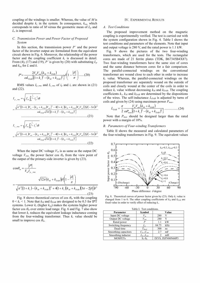
Fig. 8. Theoretical curves of power factor given by (23). Only kc value is changed from 1 to 0. The other coupling coefficients of kM and kDAB are
fixed value in order to verify effect of reducing kc.
Table I. Test conditions.
Parameter Symbol Value
Input DC voltage Vin 280 V
Output DC voltage Vout 280 V
Rated power P 1.1 kW
Switching frequency fsw 84.75 kHz
Dead time Tdead 300 ns
Smoothing capacitors Cin ,Cout 2.7 mF
Smoothing inductor Lin ,Lout 2 mH
MOSFETs S1-S8 IXYS, IXFN80N60P3
coupling of the windings is smaller. Whereas, the value of M is decided despite kc in the system. In consequence, keq, which corresponds to ratio of M versus the geometric mean of Lp and Ls is improved.
C. Transmission Power and Power Factor of Proposed
System
In this section, the transmission power P’ and the power factor of the inverter output are formulated from the equivalent circuit shown in Fig. 6. Moreover, the relationship of the power factor and the coupling coefficient kc is discussed in detail. From (4), (17) and (19), P’ is given by (20) with substituting Lp and keq for L and k.
22
1
2'
DABMcDAB
DABMoutin
kkkL
kkVVP ...... (20)
RMS values Ip_rms and Is_rms of ip and is are shown in (21)
and (22).
swfpswrmsp dtifI
1
0
2
_
22
223
13
32141
DABMcDAB
outinDABMcoutDABMinc
kkkL
VVkkkVkkVk
.............................................................................. (21)
swfsswrmss dtifI
1
0
2
_
22
223
13
32141
DABMcDAB
outinDABMcinDABMoutc
kkkL
VVkkkVkkVk
.............................................................................. (22)
When the input DC voltage Vin is as same as the output DC
voltage Vout, the power factor cos qin from the view point of
the output of the primary-side inverter is given by (23).
rmspin
inIV
P
_
'cos q
223 23141
12
DABMcDABMc
DABM
kkkkkk
kk
................................................................................... (23)
Fig. 8 shows theoretical curves of cos qin with the coupling 0 < kc < 1. Note that kM and kDAB are designed to be 0.3 for IPT systems. Lower kc (higher keq) makes the systems higher power
factor cos qin over entire load range. Fig. 6 and Fig. 7 also show that lower kc reduces the equivalent leakage inductance coming from the four-winding transformer. Thus kc value should be
small to improve cos qin.
IV. EXPERIMENTAL RESULTS
A. Test Conditions
The proposed improvement method on the magnetic
coupling is experimentally verified. The test is carried out with
the system configuration shown in Fig. 4. Table I shows the
test conditions and parameters of the elements. Note that input
and output voltage is 280 V, and the rated power is 1.1 kW.
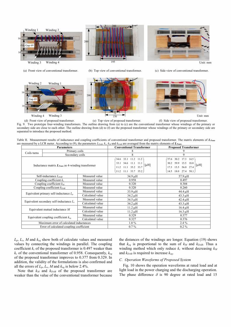
Fig. 9 shows the pictures of the two four-winding
transformers, which are used for the tests. The rectangular
cores are made of 21 ferrite plates (TDK, B67345B4X87).
Two four-winding transformers have the same size of cores
and the same distance between cores for a fair comparison.
The parallel-connected windings on the conventional
transformer are wound close to each other in order to increase
kc value. Whereas, the parallel-connected windings on the
proposed transformer are separately wound on the outside of
coils and closely wound at the center of the coils in order to
reduce kc value without decreasing kM and kDAB. The coupling
coefficients kc, kM and kDAB are determined by the dispositions
of the wires. The self-inductance LDAB is adjusted by turns of
coils and given by (24) using maximum power Pmax.
22
max 12DABMc
DABMoutinDAB
kkkP
kkVVL
................ (24)
Note that Pmax should be designed larger than the rated
power with a margin of 10%.
B. Parameters of Four-winding Transformers
Table II shows the measured and calculated parameters of
the four-winding transformers in Fig. 9. The equivalent values
Lp, Ls, M and keq show both of calculate values and measured
values by connecting the windings in parallel. The coupling
coefficient kc of the proposed transformer is 0.497 weaker than
kc of the conventional transformer of 0.958. Consequently, keq
of the proposed transformer improves to 0.377 from 0.329. In
addition, the validity of the formulations is also confirmed and
all the errors of Lp, Ls, M and keq is below 2.4%.
Note that kM and kDAB of the proposed transformer are
weaker than the value of the conventional transformer because
the distances of the windings are longer. Equation (19) shows
that keq is proportional to the sum of kM and kDAB. Thus a
winding method which only reduce kc without decreasing kM
and kDAB is required to increase keq.
C. Operation Waveforms of Proposed System
Fig. 10 shows the operation waveforms at rated load and at
light load in the power charging and the discharging operation.
The phase difference is 90 degree at rated load and 15
Winding 2Winding 1
280
200
Gap 69
16
16
Winding 4Winding 3 195 Unit: mm
(a) Front view of conventional transformer. (b) Top view of conventional transformer. (c) Side view of conventional transformer.
Winding 1Winding 2
280
200
Gap 69
16
16
Winding 3Winding 4 75
Unit: mm150
(d) Front view of proposed transformer. (e) Top view of proposed transformer. (f) Side view of proposed transformer.
Fig. 9. Two prototype four-winding transformers. The outline drawing from (a) to (c) are the conventional transformer whose windings of the primary or
secondary side are close to each other. The outline drawing from (d) to (f) are the proposed transformer whose windings of the primary or secondary side are separated to introduce the proposed method.
Table II. Measurement results of inductance and coupling coefficients of conventional transformer and proposed transformer. The matrix elements of LTrans
are measured by a LCR meter. According to (9), the parameters LDAB, kc, kM and kDAB are averaged from the matrix elements of LTrans.
Parameters Conventional Transformer Proposed Transformer
Coils turns Primary coils 8 9
Secondary coils 8 9
Inductance matrix LTrans as 4-winding transformer
2.357.331.112.11
7.332.351.112.11
1.111.116.341.33
2.112.111.336.34
[H]
1.584.270.185.14
4.270.565.153.17
0.185.159.592.30
5.143.172.306.57
[H]
Self-inductance LDAB Measured value 34.9 H 57.9 H
Coupling coefficient kc Measured value 0.958 0.497
Coupling coefficient kM Measured value 0.320 0.304
Coupling coefficient kDAB Measured value 0.320 0.260
Equivalent primary self-inductance Lp Measured value 33.9 H 44.4 H
Calculated value 34.2 H 43.3 H
Equivalent secondary self-inductance Ls Measured value 34.5 H 42.4 H
Calculated value 34.2 H 43.3 H
Equivalent mutual inductance M Measured value 11.2 H 16.4 H
Calculated value 11.2 H 16.3 H
Equivalent coupling coefficient keq Measured value 0.329 0.377
Calculated value 0.327 0.376
Maximum error of calculated inductances 1.0 % 2.4 %
Error of calculated coupling coefficient 0.7 % 0.2 %
Output power Pout W
RM
S v
alue
of
pri
mar
y c
urr
ent
I p_rm
s A
(Discharge) (Charge)
-1500 -1000 -500 0 500 1000 1500
8
10
12
14
16
18
Conventional transformer (kc=0.958)
Proposed transformer (kc=0.497)
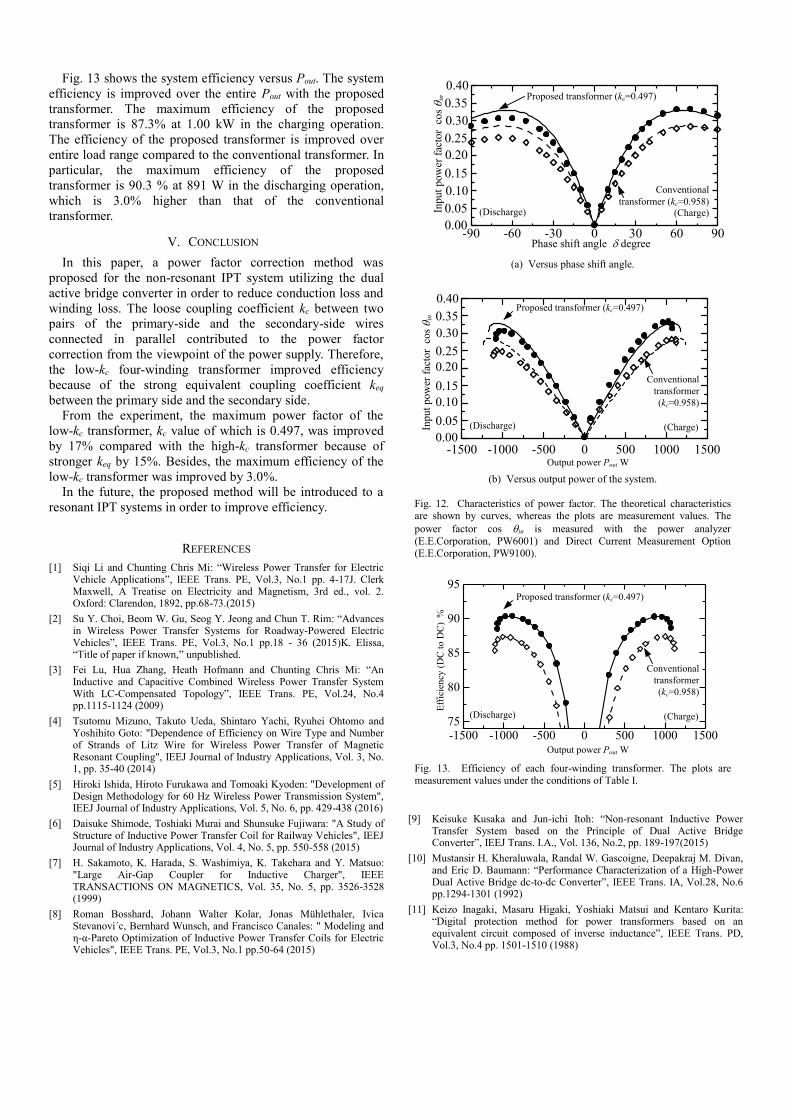
Fig. 11. Characteristics of RMS values of primary-side inverter AC output current. The theoretical characteristics are shown by curves, whereas the
plots are measurement values.
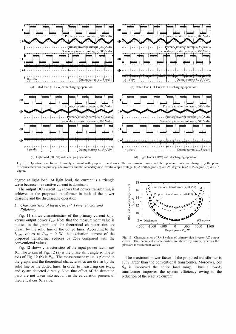
degree at light load. At light load, the current is a triangle
wave because the reactive current is dominant.
The output DC current iout shows that power transmitting is
achieved at the proposed transformer in both of the power
charging and the discharging operation.
D. Characteristics of Input Current, Power Factor and
Efficiency
Fig. 11 shows characteristics of the primary current Ip_rms
versus output power Pout. Note that the measurement value is
plotted in the graph, and the theoretical characteristics are
drawn by the solid line or the dotted lines. According to the
Ip_rms values at Pout = 0 W, the excitation current of the
proposed transformer reduces by 25% compared with the
conventional values.
Fig. 12 shows characteristics of the input power factor cos
qin. The x-axis of Fig. 12 (a) is the phase shift angle . The x-
axis of Fig. 12 (b) is Pout. The measurement value is plotted in
the graph, and the theoretical characteristics are drawn by the
solid line or the dotted lines. In order to measuring cos qin, ip
and vp are detected directly. Note that effect of the detection
parts are not taken into account in the calculation process of
theoretical cos qin value.
The maximum power factor of the proposed transformer is
17% larger than the conventional transformer. Moreover, cos
qin is improved the entire load range. Thus a low-kc
transformer improves the system efficiency owing to the
reduction of the reactive current.
0
0
0
0
Primary inverter voltage vp 500 V/div
Primary inverter current ip 50 A/div
Secondary inverter voltage vs 500 V/div
Output current iout 5 A/div8 s/div
0
0
0
0
Primary inverter voltage vp 500 V/div
Primary inverter current ip 50 A/div
Secondary inverter voltage vs 500 V/div
Output current iout 5 A/div8 s/div
(a) Rated load (1.1 kW) with charging operation. (b) Rated load (1.1 kW) with discharging operation.
0
0
0
0
Primary inverter voltage vp 500 V/div
Primary inverter current ip 50 A/div
Secondary inverter voltage vs 500 V/div
Output current iout 5 A/div8 s/div
0
0
0
0
Primary inverter voltage vp 500 V/div
Primary inverter current ip 50 A/div
Secondary inverter voltage vs 500 V/div
Output current iout 5 A/div8 s/div
(c) Light load (300 W) with charging operation. (d) Light load (300W) with discharging operation.
Fig. 10. Operation waveforms of prototype circuit with proposed transformer. The transmission power and the operation mode are changed by the phase
difference between the primary-side inverter and the secondary-side inverter output voltage. (a) = 90 degree. (b) = -90 degree. (c) = 15 degree. (b) = -15
degree.
-90 -60 -30 0 30 60 900
0.05
0.1
0.15
0.2
0.25
0.3
0.35
0.4
Phase shift angle degree
Input
pow
er f
acto
r c
os
qin
(Discharge) (Charge)
Conventional
transformer (kc=0.958)
Proposed transformer (kc=0.497)
0.30
0.20
0.10
0.00
0.40
(a) Versus phase shift angle.
Output power Pout W
(Discharge) (Charge)
Conventional
transformer
(kc=0.958)
Proposed transformer (kc=0.497)
Input
pow
er f
acto
r c
os
qin
-1500 -1000 -500 0 500 1000 15000
0.05
0.1
0.15
0.2
0.25
0.3
0.35
0.4
0.30
0.20
0.10
0.00
0.40
(b) Versus output power of the system.
Fig. 12. Characteristics of power factor. The theoretical characteristics are shown by curves, whereas the plots are measurement values. The
power factor cos qin is measured with the power analyzer
(E.E.Corporation, PW6001) and Direct Current Measurement Option
(E.E.Corporation, PW9100).
-1500 -1000 -500 0 500 1000 150075
80
85
90
95
Output power Pout W
Eff
icie
ncy
(D
C t
o D
C)
%
(Discharge) (Charge)
Conventional
transformer
(kc=0.958)
Proposed transformer (kc=0.497)
Fig. 13. Efficiency of each four-winding transformer. The plots are
measurement values under the conditions of Table I.
Fig. 13 shows the system efficiency versus Pout. The system
efficiency is improved over the entire Pout with the proposed
transformer. The maximum efficiency of the proposed
transformer is 87.3% at 1.00 kW in the charging operation.
The efficiency of the proposed transformer is improved over
entire load range compared to the conventional transformer. In
particular, the maximum efficiency of the proposed
transformer is 90.3 % at 891 W in the discharging operation,
which is 3.0% higher than that of the conventional
transformer.
V. CONCLUSION
In this paper, a power factor correction method was
proposed for the non-resonant IPT system utilizing the dual
active bridge converter in order to reduce conduction loss and
winding loss. The loose coupling coefficient kc between two
pairs of the primary-side and the secondary-side wires
connected in parallel contributed to the power factor
correction from the viewpoint of the power supply. Therefore,
the low-kc four-winding transformer improved efficiency
because of the strong equivalent coupling coefficient keq
between the primary side and the secondary side.
From the experiment, the maximum power factor of the
low-kc transformer, kc value of which is 0.497, was improved
by 17% compared with the high-kc transformer because of
stronger keq by 15%. Besides, the maximum efficiency of the
low-kc transformer was improved by 3.0%.
In the future, the proposed method will be introduced to a
resonant IPT systems in order to improve efficiency.
REFERENCES
[1] Siqi Li and Chunting Chris Mi: “Wireless Power Transfer for Electric Vehicle Applications”, IEEE Trans. PE, Vol.3, No.1 pp. 4-17J. Clerk Maxwell, A Treatise on Electricity and Magnetism, 3rd ed., vol. 2. Oxford: Clarendon, 1892, pp.68-73.(2015)
[2] Su Y. Choi, Beom W. Gu, Seog Y. Jeong and Chun T. Rim: “Advances in Wireless Power Transfer Systems for Roadway-Powered Electric Vehicles”, IEEE Trans. PE, Vol.3, No.1 pp.18 - 36 (2015)K. Elissa, “Title of paper if known,” unpublished.
[3] Fei Lu, Hua Zhang, Heath Hofmann and Chunting Chris Mi: “An Inductive and Capacitive Combined Wireless Power Transfer System With LC-Compensated Topology”, IEEE Trans. PE, Vol.24, No.4 pp.1115-1124 (2009)
[4] Tsutomu Mizuno, Takuto Ueda, Shintaro Yachi, Ryuhei Ohtomo and Yoshihito Goto: "Dependence of Efficiency on Wire Type and Number of Strands of Litz Wire for Wireless Power Transfer of Magnetic Resonant Coupling", IEEJ Journal of Industry Applications, Vol. 3, No. 1, pp. 35-40 (2014)
[5] Hiroki Ishida, Hiroto Furukawa and Tomoaki Kyoden: "Development of Design Methodology for 60 Hz Wireless Power Transmission System", IEEJ Journal of Industry Applications, Vol. 5, No. 6, pp. 429-438 (2016)
[6] Daisuke Shimode, Toshiaki Murai and Shunsuke Fujiwara: "A Study of Structure of Inductive Power Transfer Coil for Railway Vehicles", IEEJ Journal of Industry Applications, Vol. 4, No. 5, pp. 550-558 (2015)
[7] H. Sakamoto, K. Harada, S. Washimiya, K. Takehara and Y. Matsuo: "Large Air-Gap Coupler for Inductive Charger", IEEE TRANSACTIONS ON MAGNETICS, Vol. 35, No. 5, pp. 3526-3528 (1999)
[8] Roman Bosshard, Johann Walter Kolar, Jonas Mühlethaler, Ivica Stevanovi´c, Bernhard Wunsch, and Francisco Canales: " Modeling and η-α-Pareto Optimization of Inductive Power Transfer Coils for Electric Vehicles", IEEE Trans. PE, Vol.3, No.1 pp.50-64 (2015)
[9] Keisuke Kusaka and Jun-ichi Itoh: “Non-resonant Inductive Power Transfer System based on the Principle of Dual Active Bridge Converter”, IEEJ Trans. I.A., Vol. 136, No.2, pp. 189-197(2015)
[10] Mustansir H. Kheraluwala, Randal W. Gascoigne, Deepakraj M. Divan, and Eric D. Baumann: “Performance Characterization of a High-Power Dual Active Bridge dc-to-dc Converter”, IEEE Trans. IA, Vol.28, No.6 pp.1294-1301 (1992)
[11] Keizo Inagaki, Masaru Higaki, Yoshiaki Matsui and Kentaro Kurita: “Digital protection method for power transformers based on an equivalent circuit composed of inverse inductance”, IEEE Trans. PD, Vol.3, No.4 pp. 1501-1510 (1988)


![arXiv:0901.2162v1 [physics.optics] 15 Jan 2009 · Optical antennas can increase the coupling efficiency by focusing light onto an aperture region. Another important antenna type is](https://img.pdfslide.net/doc/110x75/602a89aea471ae08f4293298/arxiv09012162v1-15-jan-2009-optical-antennas-can-increase-the-coupling-eifciency.jpg)