Embed Size (px)
Citation preview

PNNL-19084
Prepared for the U.S. Department of Energy under Contract DE-AC05-76RL01830
A Survey of Wireless Communications for the Electric Power System BA Akyol H Kirkham SL Clements MD Hadley January 2010
PNNL-19084
A SURVEY OF WIRELESS COMMUNICATIONS FOR THE ELECTRIC POWER SYSTEM BA Akyol H Kirkham SL Clements MD Hadley January 2010 Prepared for the U.S. Department of Energy under Contract DE-AC05-76RL01830 Pacific Northwest National Laboratory Richland, Washington 99352

iii
Executive Summary
A key mission of the U.S. Department of Energy (DOE) Office of Electricity Delivery and Energy Reliability (OE) is to enhance the security and reliability of the nation’s energy infrastructure. Improving the security of control systems, which enable the automated control of our energy production and distribution, is critical for protecting the energy infrastructure and the integral function that it serves in our lives. The DOE-OE Control Systems Security Program provides research and development to help the energy industry actively pursue advanced security solutions for control systems.
The focus of this report is analyzing how, where, and what type of wireless communications are suitable for deployment in the electric power system and to inform implementers of their options in wireless technologies. The discussions in this report are applicable to enhancing both the communications infrastructure of the current electric power system and new smart system deployments.
The work described in this report includes a survey of the following wireless technologies:
IEEE 802.16 d and e (WiMAX)
IEEE 802.11 (Wi-Fi) family of a, b, g, n, and s
Wireless sensor protocols that use parts of the IEEE 802.15.4 specification: WirelessHART, International Society of Automation (ISA) 100.11a, and Zigbee
The 2, 3, and 4 generation (G )cellular technologies of GPRS/EDGE/1xRTT, HSPA/EVDO, and Long-Term Evolution (LTE)/HSPA+UMTS.
In this document, we provide a concise summary of the technical underpinnings of each wireless technology. We also outline the feature set and the strengths and weaknesses of each technology. Our intent is to provide enough detail to our readers such that when considering wireless for a particular application, they will know enough to ask the right questions to get the features and capabilities desired.
For obtaining data communications coverage quickly and inexpensively over a large geographic area, both WiMAX and 3G/4G cellular technologies should be considered. WiMAX at the present holds a bandwidth and latency advantage over 3G cellular communications; however, with the imminent LTE deployment from multiple carriers, we believe this advantage will be short-lived. Unlike WiMAX deployments, LTE will mostly reuse existing cellular networks and should be a straightforward evolution of the 3G cellular networks. Both of these technologies operate over licensed spectrum and therefore should be protected against unintended interference. In terms of scalability, we know that the cellular networks are capable of accommodating hundreds of millions of subscribers while providing both voice and data communications. WiMAX networks have been deployed to provide wireless local loop service successfully. However, presently, WiMAX networks only support a small fraction of users compared to 3G cellular networks. Whether using WiMAX or 3G/4G cellular, we recommend a combination of application-level security and virtual private networking (VPN) for transporting electric power system information over these public networks.
For creating a wireless sensor network for both data gathering and command/control applications, there are three alternatives, all based on the IEEE 802.15.4 protocol stack: ZigBee, WirelessHART, and ISA100.11a. We expect ZigBee to be a common choice for electric power system networking within the
iv
home. While there are legitimate concerns for the security properties of ZigBee as we will discuss in this report, these concerns can be addressed and should be acceptable for use in the home environment. For transporting data from a customer premise back to an operations center, we expect 3G/4G cellular and WiMAX to be the dominant choices. For wireless sensor network applications elsewhere in the electric power system, such as a substation or a generation plant, we recommend WirelessHART or ISA100.11a. These two standards are very similar in functionality, and either standard is suitable for deployment. Wi-Fi, while being used in many municipal deployments to provide data communications service, is in our opinion not suitable for deployment in the electric power system other than inside a residence as a replacement for ZigBee. Wi-Fi does not provide the reliable wide-area coverage and predictable latencies that are expected for an electric power system application. While offering improved security with the 802.11-2007 specification, the operation in the unlicensed bands would be unacceptable for transporting electric power system data over a wide area.
v
Acronyms and Abbreviations
2G second generation
3DES Triple Data Encryption Standard
3G third generation
4G forth generation
ACK acknowledge
AES Advanced Encryption Standard
AES Advanced Encryption Standard
AODV Ad-hoc On-Demand Distance Vector
AS
BIOS
authentication servers
basic input/output system
BS base stations
CA collision avoidance
CCA Clear Channel Assessment
CDMA Code Division Multiple Access
CFP Contention Free Period
CSMA carrier sense multiple access
CTS clear-to-send
DCF distributed coordination function
DL Downlink or Data Link Layer
DoS denial of service
DSL Digital Subscriber Line
DSSS Direct Sequence Spread Spectrum
EAP Extensible Authentication Protocol
EAP Extensible Authentication Protocol
EDGE Enhanced Data rates for GSM Evolution
EV-DO Evolution-Data Optimized
FDMA frequency division multiple access
GPRS General Packet Radio Service
GTS Guaranteed Time Slots
HAN Home Area Networks
HART Highway Addressable Remote Transducer
HSPA High-Speed Packet Access
IEEE Institute of Electrical and Electronics Engineers
IETF Internet Engineering Task Force
IP Internet Protocol
LTE Long-Term Evolution
vi
MIC message integrity check
MIMO Multiple-Input-Multiple-Output
MITM man-in-the-middle
NIST National Institute for Standards and Technology
PCF Point Coordination Function
PDU Protocol Data Unit
QoS quality of service
RF Radio Frequency
RSNA Robust Security Network Architecture
RTS request-to-send
SAE System Architecture Evolution
SCADA supervisory control and data acquisition
SDU Service Data Unit
SGN smart grid nodes
SIM Subscriber Identity Module
STA IEEE 802.11 client station
TDMA Time Division Multiple Access
TKIP Temporal Key Integrity Protocol
TL transport layer
TLS Transport Layer Security
TSMP Time Synchronized Mesh Protocol
TTLS Tunneled Transport Layer Security
WEP Wired Equivalent Privacy
WLAN wireless local area networks
WSN Wireless Sensor Network
vii
Glossary
ACL Access Control List. An ACL uses a device identifier to look up the access level granted to that device.
AES Advanced Encryption Standard. AES is defined in FIPS 197 by NIST.
AODV Ad-hoc On-Demand Distance Vector routing algorithm is a routing algorithm designed for ad-hoc mobile networks. AODV performs both unicast and multicast routing. It is an on-demand algorithm that builds routes between nodes only when there is an information exchange. It maintains these routes only as long as they are needed. It scales to large numbers of nodes.
BSS Basic Service Set. In an IEEE 802.11 wireless local area network, the BSS refers to an access point and devices associated with it.
BSSID Basic Service Set Identifier. BSSID is the name associated with a particular wireless LAN.
CDMA Code Division Multiple Access. CDMA allows access to a communications channel by multiple users where the data being sent by each user is modulated by a pseudo-noise sequence.
Confidentiality Confidentiality has been defined by the International Organization for Standardization (ISO) in ISO-17799 as “ensuring that information is accessible only to those authorized to have access” and is one of the cornerstones of information security.
FCS Frame Check Sequence. A sequence of bits that come at the end of a data communication frame and are used to verify the validity of the frame by means of a validation algorithm.
FFT/IFFT Fast Fourier Transform, Inverse Fast Fourier Transform. A method to convert signals from time domain to frequency domain or vice versa.
Goodput Goodput is commonly used to refer the proportion of data when received that can be used by an application. For example, if an application sends information in N segments, and the network has to retransmit these segments M times to get them across, the goodput of the network is N/M.
HAN Home Area Network. A sensor network that is used inside a home. A HAN is self-configuring and uses very low-power communications.
IBSS Independent Basic Service Set. In an IEEE 802.11 wireless local area network that operates in ad-hoc mode where there are no access points present, an IBSS refers to all devices that are part of the ad-hoc network.
viii
Integrity (of data) Integrity of data is the assurance that it has not been altered during storage or communication. Integrity of data is usually checked by means of a cryptographic hash function.
ISA100.11a ISA100.11a is a wireless sensor network protocol standard developed by the International Society of Automation.
Jitter For an event that is periodic, the jitter is the deviation from the assumed period of the event.
KASUMI KASUMI is a block cipher that provides both encryption and integrity services. KASUMI is used in cellular networks based on the Global System of Mobile Communications (GSM) standard.
Latency Latency is the time it takes for a packet to travel from the origin to the destination and back. It excludes the processing time in the destination. Latency includes the media access time and any queuing and propagation delays.
Message Digest A message digest is a checksum computed for a message typically using a one-way cryptographic hash function. The purpose of the message digest is to ensure the detection of any accidental or intentional change in the contents of the message.
Nonce A nonce is a number used only once. In the cryptographic sense, a nonce is a random or a pseudo-random number that has two uses. The first use is to prevent a replay of the message being sent. The second use is to act as the initialization vector for a cipher such as AES.
ORYX ORYX is an encryption algorithm based on the logical XOR operation. ORYX was used by CDMA-based cellular phone networks but is being phased out due to various security issues.
PN Sequence Pseudo-noise sequence. A PN sequence is used in direct sequence spread spectrum networks (e.g., CDMA) to modulate the transmission in order to allow multiple users to access the channel simultaneously. Each PN sequence is (almost) orthogonal to all other PN sequences.
TDMA Time Division Multiple Access. TDMA divides a communication channel into time slots where each user is allowed to transmit or receive in his or her designated time slot.
TMTO Time Memory Trade Off. TMTO is an attack methodology first defined by Hellman. TMTO precomputes a table of potential results of a one-way function in order to speed up the computation of the input.
ix
TSMP Time Synchronized Mesh Protocol was developed by Dust Networks in order to provide routing and media access control for wireless sensor networks. TSMP uses TDMA for multiple access and is the basis for the WirelessHART standard from the HART foundation.
UMTS Universal Mobile Telecommunications System. UMTS is a 3G mobile telecommunications technology. The most common form of UMTS uses Wideband-CDMA.
VAr In alternating current power transmission and distribution, volt-ampere-reactive (VAr) is a unit used to measure the reactive power in the AC electric power system.
Wi-Fi Wi-Fi refers to wireless networks that use the IEEE 802.11 standard.
WiMAX WiMAX refers to wireless networks that use the IEEE 802.16 standard.
WSN Wireless Sensor Network. A network that is mainly used to interconnect sensors to a controller.
ZigBee ZigBee is a wireless standard that is used in wireless sensor and home automation networks. IEEE 802.15.4 protocol stack was standardized as part of ZigBee development.

xi
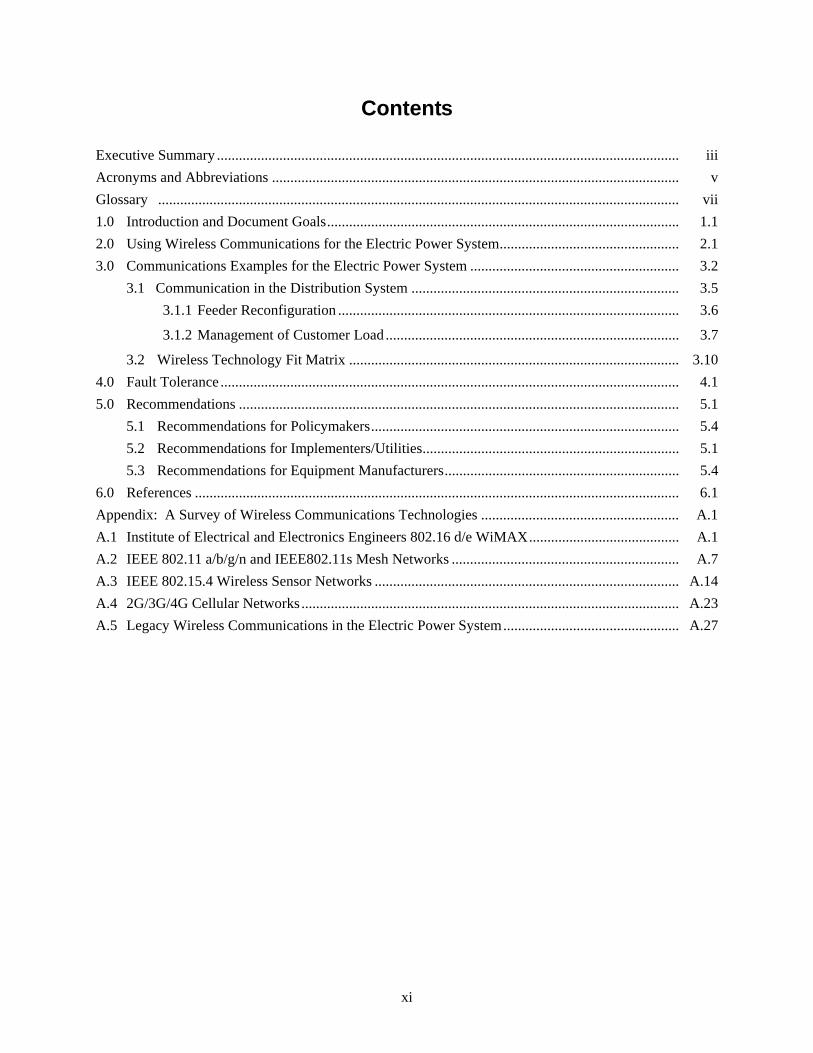
Contents
Executive Summary .............................................................................................................................. iii
Acronyms and Abbreviations ............................................................................................................... v
Glossary .............................................................................................................................................. vii
1.0 Introduction and Document Goals ................................................................................................ 1.1
2.0 Using Wireless Communications for the Electric Power System ................................................. 2.1
3.0 Communications Examples for the Electric Power System ......................................................... 3.2
3.1 Communication in the Distribution System ......................................................................... 3.5
3.1.1 Feeder Reconfiguration ............................................................................................. 3.6
3.1.2 Management of Customer Load ................................................................................ 3.7
3.2 Wireless Technology Fit Matrix .......................................................................................... 3.10
4.0 Fault Tolerance ............................................................................................................................. 4.1
5.0 Recommendations ........................................................................................................................ 5.1
5.1 Recommendations for Policymakers .................................................................................... 5.4
5.2 Recommendations for Implementers/Utilities ...................................................................... 5.1
5.3 Recommendations for Equipment Manufacturers ................................................................ 5.4
6.0 References .................................................................................................................................... 6.1
Appendix: A Survey of Wireless Communications Technologies ...................................................... A.1
A.1 Institute of Electrical and Electronics Engineers 802.16 d/e WiMAX ......................................... A.1
A.2 IEEE 802.11 a/b/g/n and IEEE802.11s Mesh Networks .............................................................. A.7
A.3 IEEE 802.15.4 Wireless Sensor Networks ................................................................................... A.14
A.4 2G/3G/4G Cellular Networks ....................................................................................................... A.23
A.5 Legacy Wireless Communications in the Electric Power System ................................................ A.27
xii
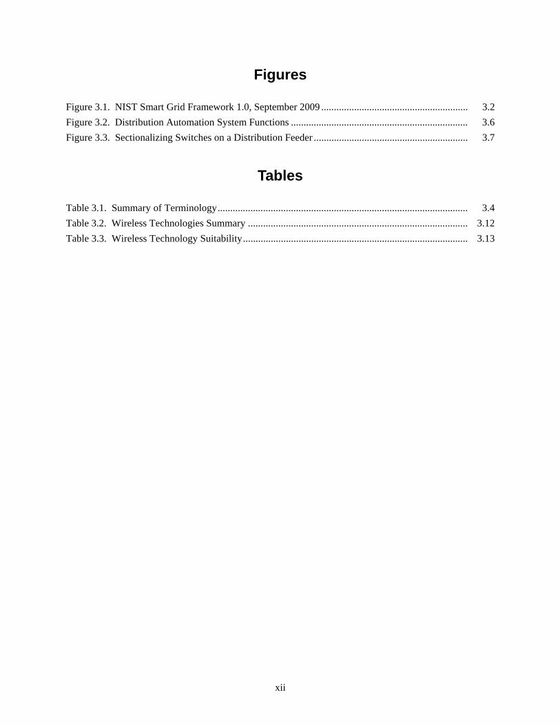
Figures
Figure 3.1. NIST Smart Grid Framework 1.0, September 2009 .......................................................... 3.2
Figure 3.2. Distribution Automation System Functions ...................................................................... 3.6
Figure 3.3. Sectionalizing Switches on a Distribution Feeder ............................................................. 3.7
Tables
Table 3.1. Summary of Terminology ................................................................................................... 3.4
Table 3.2. Wireless Technologies Summary ....................................................................................... 3.12
Table 3.3. Wireless Technology Suitability ......................................................................................... 3.13

1.1
1.0 Introduction and Document Goals
Wireless communication continues to play a significant role in the modernization of the electric power system. Examples of modernization efforts related to increased communications in the electric power system to improve reliability and efficiency include but are not limited to:
Electric power system operations: Control and monitoring networks throughout the electric power system. Sensors are installed to monitor the generation and delivery systems and power use in the system. These operational sensing and control networks can be further classified according to their location:
– Home Area Networks (HANs): Inside the home, a wireless network can link the various appliances and a central controller. This network will likely interface to the utility network via a link that involves the metering function. The metering network serves as a communication channel for a variety of operational signals, so that both metering and operational data are carried on this section of the network. One of the signals carried by the advanced metering infrastructure is a price-based incentive signal. The incentive signal is one way for a utility to implement “demand response.”
– Distribution Automation: The medium voltage part of the power delivery network is the link from the networked transmission system to the load. Often operated at voltages less than 70 kV, this part of the delivery system has long been considered uneconomical to operate with extensive monitoring outside of the substations.
– Substation Automation: In contrast to the feeders and lines of the distribution system, the substations are monitored. Circuit currents and voltages are checked here, as well as performance parameters of the station apparatus. We can also use wireless devices to perform physical surveillance.
– At higher voltages are the transmission system (voltages up to 765 kV in the U.S.) and the generators that are connected to it. The transmission systems have their own communications needs.
– Power Plants: Wireless communications can be used to deploy sensors in locations where wired sensor deployment may be difficult. Physical surveillance may be improved by adding wireless video cameras and motion detectors.
Financial Operations Network: Financial operations network handles billing, accounting, and energy settlements.
It is important to note that there is no single implementation that will define the communications architecture of the electric power system. An implementation in California will be different from an implementation in Massachusetts; therefore, the communications requirements for the networks that are part of the system are repeated with some differences in each utility and region. The electric power system will require communications with great flexibility and complexity.
The purpose of this document is to analyze how, where, and what type of wireless communications capabilities are suitable for deployment in the electric power system. A second purpose is to inform system operators about their options in wireless technologies. We discuss examples of wireless applications and deployment scenarios and summarize each wireless technology’s vulnerabilities.

1.2
Sections 2 and 3 discuss example application areas for wireless communications in the electric power system, including examples about smart system deployments. In Section 4, we briefly discuss fault tolerance. Section 5 presents our recommendations on how wireless communications should be used in the electric power system. Appendix A presents a technical summary of competing and complementary technologies and can be used as a reference.

2.1
2.0 Using Wireless Communications for the Electric Power System
Wireless communications1 provide both flexibility and cost savings in deployment and maintenance compared to wireline deployments. Wireless can be deployed anywhere and anytime. No trenches or conduits are required. Wireless networks using mesh technology such as WirelessHART can route around not only single but also multiple node failures. Sensors that use IEEE 802.15.4 based radio transceivers (e.g., ISA100.11a) can function for several years with an internal battery in harsh environments without requiring any external power. A sensor that has wireless capabilities can be easily relocated and when required, additional supplementary sensors can be deployed in most cases within a few hours. To summarize, with wireless communications we gain ease of deployment, flexibility, and cost savings.
Common challenges associated with wireless communications are probabilistic channel behavior, accidental and directed interference or jamming, and eavesdropping or unauthorized modification of the communications if not protected by authentication and encryption. A wireless communication network without proper security protocols can be exploited with a man-in-the-middle attack.2 The result could be both loss of service and loss of confidentiality.
Wireless-based systems have been used in industries similar to the electric power system such as oil and gas. For example, British Petroleum has successfully deployed WirelessHART, which is an extension of the HART protocol. In the oil and gas industries, perception is that wireless is at least acceptable for deployment in monitoring applications [Petersen et al. 2008a; Petersen et al. 2008b].
In Section 3, we will discuss communication examples for the electric power system and produce a wireless fit matrix for our examples.
1 This document focuses solely on wireless communication technologies that use radio frequencies and not infrared or free-space lasers. 2 A man-in-the-middle attack is executed by an adversary that is able to insert itself into the communications path between two parties and act as a go-between. The adversary is then able to delete, modify, or add information to the communication channel. Protocols that perform mutual authentication of all parties that are part of the conversation are not vulnerable to this attack.
3.2
3.0 Communications Examples for the Electric Power System
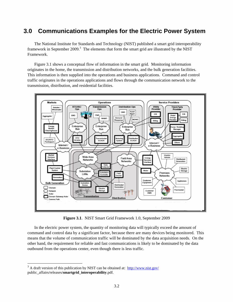
The National Institute for Standards and Technology (NIST) published a smart grid interoperability framework in September 2009.3 The elements that form the smart grid are illustrated by the NIST Framework.
Figure 3.1 shows a conceptual flow of information in the smart grid. Monitoring information originates in the home, the transmission and distribution networks, and the bulk generation facilities. This information is then supplied into the operations and business applications. Command and control traffic originates in the operations applications and flows through the communication network to the transmission, distribution, and residential facilities.
Figure 3.1. NIST Smart Grid Framework 1.0, September 2009
In the electric power system, the quantity of monitoring data will typically exceed the amount of command and control data by a significant factor, because there are many devices being monitored. This means that the volume of communication traffic will be dominated by the data acquisition needs. On the other hand, the requirement for reliable and fast communications is likely to be dominated by the data outbound from the operations center, even though there is less traffic.
3 A draft version of this publication by NIST can be obtained at: http://www.nist.gov/ public_affairs/releases/smartgrid_interoperability.pdf.
3.3
Control and command requires a highly secure channel. Billing information must also be secure. While the information coming from the residence may be of lower importance, it still needs to be secured to guarantee confidentiality and integrity of customers’ metering information.
The remainder of this section discusses, by means of examples, the requirements for communication between the various parts identified in the NIST framework.
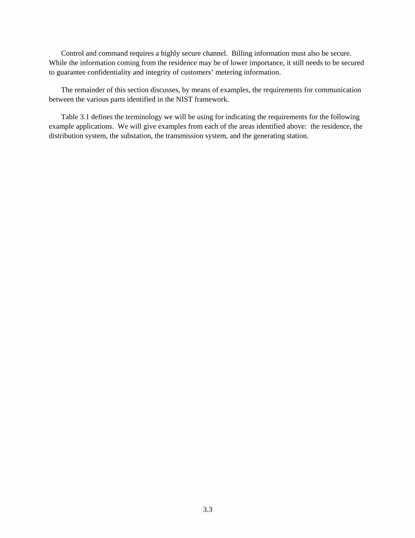
Table 3.1 defines the terminology we will be using for indicating the requirements for the following example applications. We will give examples from each of the areas identified above: the residence, the distribution system, the substation, the transmission system, and the generating station.
3.4
Table 3.1. Summary of Terminology
Data Rate (average)
Latency4 (average)
Reliability Security Distance/Range Scalability
Low < 500 Kbps < 250 ms Packet loss is acceptable (It is expected that applications will recover from packet loss at the expense of added delays in communications.)
Clear text communications, integrity checks may or may not be used.
< 100 meters < 100 Nodes / Backhaul Node
Moderate 500 Kbps – 1,500 Kbps
250 ms – 1 s Some (minimal) packet loss is acceptable.
Confidentiality may be required, integrity checks are required.
100 meters – 1000 meters
100 – 1000 Nodes / Backhaul Node
High > 1,500 Kbps
> 1 s Fully reliable communications with error recovery at the data link layer.
Confidentiality and integrity checks are required.
> 1000 meters > 1000 Nodes / Backhaul Node
4 Latency is the time it takes for a packet to travel from the origin to the destination and back. It excludes the processing time in the destination. Latency includes the media access time, any queuing and propagation delays.

3.5
3.1 Communication in the Distribution System
In some respects the distribution system is the key to the changes in the electric power system. Most of the examples we will look at here already have communication solutions, either in place or under development. That is less true for the distribution system itself. Outside of the substation, most of the distribution system operates without being monitored and without a great deal of automatic control.1 If the system is to be modernized, the distribution system itself will become more extensively monitored, and more closed loop control will be incorporated.
Collectively, the control applications in the medium- and low-voltage part of the power delivery system are typically called “distribution automation.” Functions include:
managing customers’ loads
monitoring the performance of the power system itself
reading customers’ meters, perhaps even several times per hour
detecting stolen energy
controlling voltage in the power system
detecting outages
reconfiguring the system following a fault
balancing loads for optimal system operation
collecting load data for system planning.
Each of these functions will have its own communication requirements. For the purposes of discussing communications, distribution automation can be divided into three separate geographical parts:
1. The distribution substation, including the transformers that take the power from the bulk system, and the buses and breakers that send the power out of the station at low voltage
2. The low-voltage feeders and transformers, i.e., the equipment up to the customer's meter
3. The equipment on the customer’s side of the meter, including load control equipment and customer-owned generation.
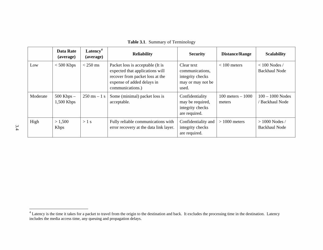
Figure 3.1 shows some of the functions performed by a distribution automation system. We will examine some of the functions of feeder reconfiguration and customer load management.
1 Voltage, if it is controlled, is often governed by a time-clock operating in an open-loop manner, for example. Such a strategy avoids the need for communications.
3.6
Figure 3.2. Distribution Automation System Functions
3.1.1 Feeder Reconfiguration
Wireless communication is an excellent candidate for feeder reconfiguration. Let’s examine why that is the case.
Outside the distribution substation, the distribution automation system can perform equipment monitoring (similar in function to substation automation) and feeder automation.2 Feeder automation, which can be defined as monitoring and control of the system from the substation to the customer's meter, may have many objectives. An important one is to increase system availability by reconfiguring the distribution system automatically. This may be done to reduce losses by balancing the load among different feeders, or to remove the minimum amount of a system following a fault, or to restore as much load as possible after a fault has been isolated. Some of this control requires knowledge of where the load is in terms of its distribution along any given feeder. This could be approximated ahead of time, or the distribution automation system itself could furnish the data in real time.
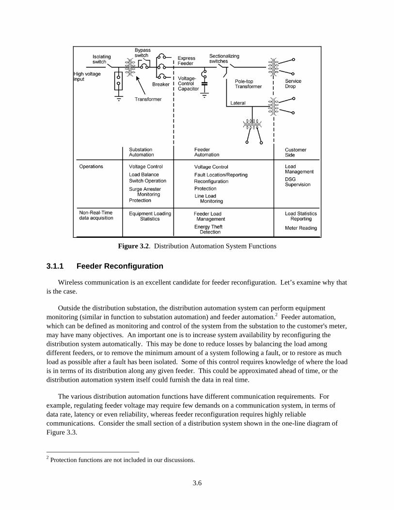
The various distribution automation functions have different communication requirements. For example, regulating feeder voltage may require few demands on a communication system, in terms of data rate, latency or even reliability, whereas feeder reconfiguration requires highly reliable communications. Consider the small section of a distribution system shown in the one-line diagram of Figure 3.3.
2 Protection functions are not included in our discussions.
3.7
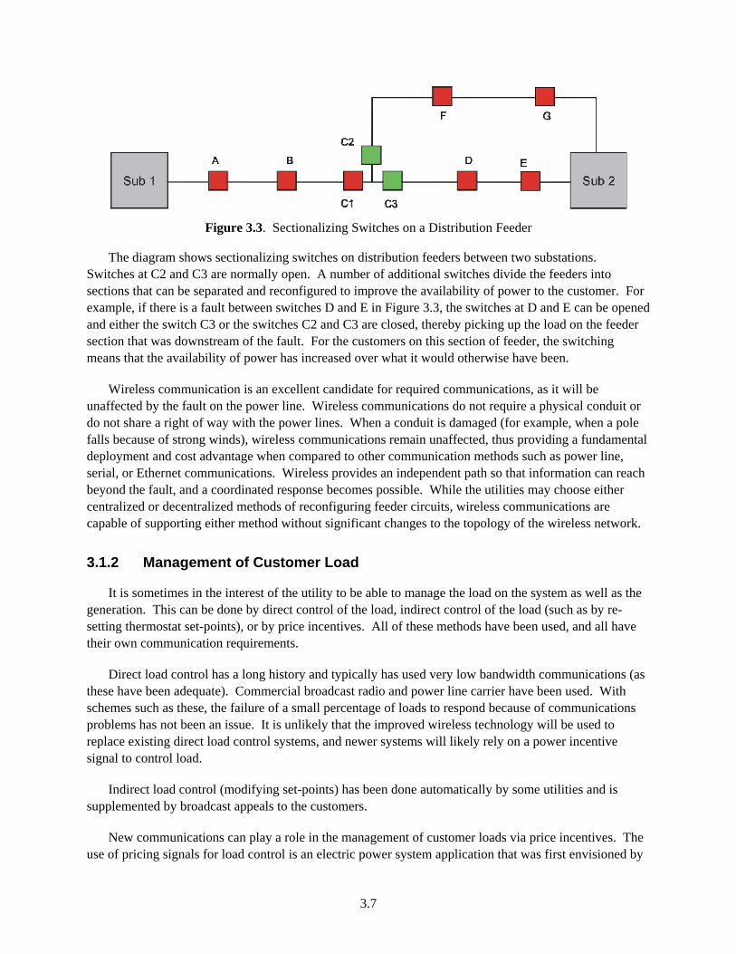
Figure 3.3. Sectionalizing Switches on a Distribution Feeder
The diagram shows sectionalizing switches on distribution feeders between two substations. Switches at C2 and C3 are normally open. A number of additional switches divide the feeders into sections that can be separated and reconfigured to improve the availability of power to the customer. For example, if there is a fault between switches D and E in Figure 3.3, the switches at D and E can be opened and either the switch C3 or the switches C2 and C3 are closed, thereby picking up the load on the feeder section that was downstream of the fault. For the customers on this section of feeder, the switching means that the availability of power has increased over what it would otherwise have been.
Wireless communication is an excellent candidate for required communications, as it will be unaffected by the fault on the power line. Wireless communications do not require a physical conduit or do not share a right of way with the power lines. When a conduit is damaged (for example, when a pole falls because of strong winds), wireless communications remain unaffected, thus providing a fundamental deployment and cost advantage when compared to other communication methods such as power line, serial, or Ethernet communications. Wireless provides an independent path so that information can reach beyond the fault, and a coordinated response becomes possible. While the utilities may choose either centralized or decentralized methods of reconfiguring feeder circuits, wireless communications are capable of supporting either method without significant changes to the topology of the wireless network.
3.1.2 Management of Customer Load
It is sometimes in the interest of the utility to be able to manage the load on the system as well as the generation. This can be done by direct control of the load, indirect control of the load (such as by re-setting thermostat set-points), or by price incentives. All of these methods have been used, and all have their own communication requirements.
Direct load control has a long history and typically has used very low bandwidth communications (as these have been adequate). Commercial broadcast radio and power line carrier have been used. With schemes such as these, the failure of a small percentage of loads to respond because of communications problems has not been an issue. It is unlikely that the improved wireless technology will be used to replace existing direct load control systems, and newer systems will likely rely on a power incentive signal to control load.
Indirect load control (modifying set-points) has been done automatically by some utilities and is supplemented by broadcast appeals to the customers.
New communications can play a role in the management of customer loads via price incentives. The use of pricing signals for load control is an electric power system application that was first envisioned by
3.8
Schweppe in 1978 [Schweppe et al. 1980] but became practical only with the advances in communication and microprocessor technology and the deregulation of the power system. This method assumes that the electric power system is in communication with a smart house and requires communication within the customer premise and between the customer premise and the utility. We will examine these separately.
3.1.2.1 Communication within a Customer Premise
This application illustrates communications within a customer premise in the context of a smart grid deployment. The smart grid nodes (SGNs) in a customer premise include large and small appliances, heating, ventilation, and air conditioning, water heaters, entertainment devices, plug-in vehicle chargers, computers, and the smart meter. The smart meter communicates with the SGNs to collect usage information and to distribute metering rate schedules. When initiated by the utility, the smart meter may also assert an incentive signal to cause the SGNs to switch to a power-saving profile. This application requires low data rates because the amount of information exchanged is not large, but it needs high security to protect customer information. The reliability requirement is moderate. It is acceptable to miss a few packets once in a while, but the system needs to function well enough to provide benefits to both the customer and the utility. In this application, there could be interference from a number of wireless devices, including cellular and wireless local area networks, radio frequency remotes, Bluetooth, microwaves, etc. Available communication options include wireless and powerline. Wired networks such as Ethernet are too restrictive to be used in most residences for SGNs due to lack of Ethernet wiring. In this example, moderate- to high-latency communications are acceptable. Note that any communication scheme used within a residence must allow the residence owner to decide which devices are “in network” and which are not. Specifically, in areas of high population density, the smart meter must be able to differentiate SGNs that belong to each residence owner. A wireless network can meet all these requirements, and indeed HANs are being constructed based on IEEE 802.11 and IEEE 802.15.4. A number of systems that use the power wiring itself for communicating within the home3 also exist and are being used.
3.1.2.2 Communication between the Customer Premise and the Local Distribution Control Center
This application connects the in-premise smart grid network of our previous example to the power utility. It is conceivable for every smart grid enabled device in the residence to communicate directly back to the utility distribution operations center, but this approach is currently not adopted. Instead, the smart meter at the customer premise performs as a gateway that translates, summarizes and aggregates data from the premise and presents it to the local power utility. This traffic may be moved over a wired or wireless network to the operations center. Additionally, the smart meter transfers the cost signals from the power utility to the devices in the premise. The data rates for this application are expected to be low to moderate depending on the number of devices in the network. An individual session may present a low average data rate depending on the frequency of communication, but the network must support hundreds of concurrent sessions. This network must be fairly reliable and highly secure, as it will contain billing data. This example also requires robustness with respect to loss of intermediate nodes and jamming. Expected interferers are cellular and wireless local area networks, radio frequency remotes, Bluetooth,
3 For example, Echelon is one of many companies that make powerline networking equipment: http://www.echelon.com/Products/Transceivers/.
3.9
microwaves, etc. Communication options are wired networks (DSL, cable modem, powerline), and wireless networks such as cellular, IEEE 802.11 and IEEE 802.15.4 networks. Latency is not a major factor in this example.
3.1.2.3 Communication within a Substation or a Distribution Station
In a substation or a distribution station, there is the need to measure voltages and currents associated with transformers, circuit breakers, and switches. Power quality sensors, transformer temperature sensors, and breaker position indicators may also be needed. Physical security monitoring equipment (e.g., video cameras, motion sensors, etc.) may be used. This application requires low to moderate data rates, high reliability, multiple classes of traffic, moderate reach (1-5 square miles), and high security. There may be interference from high-voltage lines, cellular and wireless local area networks, or microwave transmission facilities. The communications equipment will be exposed to temperature extremes and may need to operate even during a power failure. Moderate communication latency is expected. Communication options are wired networks such as Ethernet and serial links and wireless networks such as IEEE 802.11 and IEEE 802.15.4.
3.1.2.4 Communication within a Bulk Generation Plant
A bulk generation plant may contain several generation units. Each generation unit may contain several hundred sensors to measure parameters such as steam temperature and air, water, or fuel flow rates. All of this information is fed into the data acquisition system in the plant. Additionally, each generation unit may contain several hundred actuators that control fuel, air, and water flows to optimize heat rate (efficiency of the generator); control emissions, and adjust generator output. Transformers increase the voltage to a value suitable for transfer over long distances. The transmission facilities contain sensors to monitor power parameters and transformer operating parameters such as temperature. Finally, the physical security of the plant is monitored by intrusion sensors, video cameras, and motion sensors. In order to successfully manage and operate the plant, the control and data acquisition systems are integrated into a plant management platform. The physical security system may be either integrated or kept as a separate system. This example requires moderate to high data rates due to the number of devices connected to the network. High reliability is paramount as is the ability to support multiple classes of traffic. A power plant can cover a geographic area of several square miles; therefore, a medium to long reach network is required. The environment will contain interference from high-voltage lines, transformers, cellular and wireless local area networks, and microwave transmission facilities. The communications equipment will be exposed to temperature extremes and may need to operate even during a power failure. This application expects low latency communication. In the past, the comprehensive physical security and isolated networks in a power plant have inherently led to a measure of cyber security. In the future, as more control and automation systems get networked, and wireless sensor networks are added to provide a variety of functions including location and inventory services, sensing and physical security, we expect network security to become as important as physical security of the plant. Inside a generation plant, we expect most communications to happen over either Ethernet or serial links. Wireless networks can supplement existing communications capabilities to provide additional sensors for both process control and surveillance. We expect IEEE 802.11 to be used for surveillance purposes and WirelessHART or ISA100.11a to be used for wireless sensor deployments.
3.10
3.1.2.5 Communication between the Transmission Network and Operations Center
The transmission network can cover an extremely large geographic area. Some lines and stations may be located in remote regions where there is no coverage from conventional public communication networks, and utilities have typically installed microwave links to reach such locations. The transmission network contains multiple sensors to monitor power-related parameters such as current and voltage, and switch and tap-changer positions. Some equipment temperatures and environmental parameters may be measured. These measurements are made in transmission stations. Equipment may also be placed at strategic locations inside and outside the stations to ensure the physical security of the transmission facilities. This application requires moderate data rates, high reliability, and long-reach coverage that may require multiple types of networks to be present. External interference from high-voltage lines, cellular networks, and other wireless networks is possible. This application demands support for multiple classes of service. For example, physical surveillance traffic will need to be carried on a different class of service than power information. Because up-to-date knowledge of the status of the transmission facilities is critical to power system operation, low or moderate latency communication is expected. For monitoring of the transmission network, we expect wireless technologies to play a major role. Specifically, both WiMAX and 3G/4G cellular networks can provide wide-area data network coverage. For areas not reached by these networks, point to point microwave links can be used.
3.1.2.6 Communication between the Bulk Generation Plant and Operations Center
The communication between a bulk generation plant and a power system operation center consists of the summarized status of the power plant and generally does not contain all of the sensor data being consumed within the plant. An exception to this case is a remotely operated plant such as a distributed generator. Depending on whether the plant provides summarized state information or is remotely monitored, the data rates required by this use case may be low to moderate. High reliability is required because the generation status is a key part of the power system management. If the power plant is being controlled locally, then a single class of traffic may be sufficient because every piece of information coming out of the plant has a high priority. For power plants that are being controlled remotely, multiple classes of service are required. If these communications traverse a public wide-area network, they need to be secure (confidentiality and integrity). Latency must be managed in order to improve command and control response times. For communicating between the operations center and a bulk generation plant, we expect a wired wide-area link (e.g., a T1 line) to be used. Even in cases where such a link may be available, we expect WiMAX and 3G/4G cellular networks to be used as a backup communication link. For distributed generation, we expect both WiMAX and 3G/4G cellular networks to be the first choice of communication unless the existing internet connectivity at the customer premise is used.
3.2 Wireless Technology Fit Matrix
In this document, we have given multiple examples of communications in the electric power system. This section provides our opinions on where and what type of wireless communications fit these examples. One key observation is that electric power system deployments will vary greatly based on geographic region, communications coverage, and population density. Therefore, the conclusions reached in this section should be considered only as representative examples. The implementers should conduct a thorough analysis based on their own requirements.
3.11
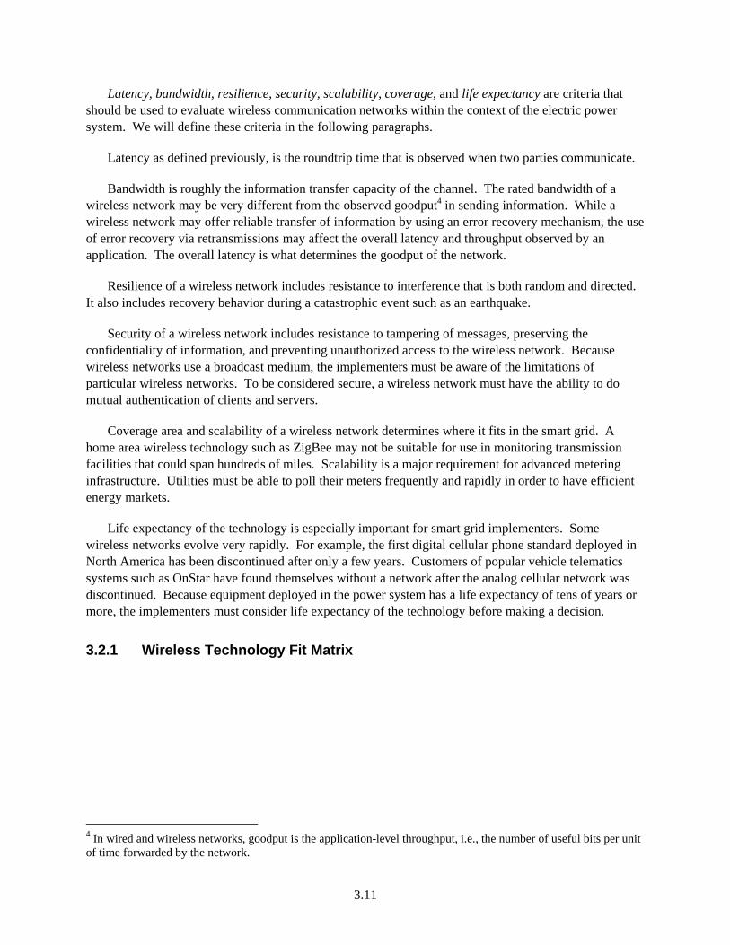
Latency, bandwidth, resilience, security, scalability, coverage, and life expectancy are criteria that should be used to evaluate wireless communication networks within the context of the electric power system. We will define these criteria in the following paragraphs.
Latency as defined previously, is the roundtrip time that is observed when two parties communicate.
Bandwidth is roughly the information transfer capacity of the channel. The rated bandwidth of a wireless network may be very different from the observed goodput4 in sending information. While a wireless network may offer reliable transfer of information by using an error recovery mechanism, the use of error recovery via retransmissions may affect the overall latency and throughput observed by an application. The overall latency is what determines the goodput of the network.
Resilience of a wireless network includes resistance to interference that is both random and directed. It also includes recovery behavior during a catastrophic event such as an earthquake.
Security of a wireless network includes resistance to tampering of messages, preserving the confidentiality of information, and preventing unauthorized access to the wireless network. Because wireless networks use a broadcast medium, the implementers must be aware of the limitations of particular wireless networks. To be considered secure, a wireless network must have the ability to do mutual authentication of clients and servers.
Coverage area and scalability of a wireless network determines where it fits in the smart grid. A home area wireless technology such as ZigBee may not be suitable for use in monitoring transmission facilities that could span hundreds of miles. Scalability is a major requirement for advanced metering infrastructure. Utilities must be able to poll their meters frequently and rapidly in order to have efficient energy markets.
Life expectancy of the technology is especially important for smart grid implementers. Some wireless networks evolve very rapidly. For example, the first digital cellular phone standard deployed in North America has been discontinued after only a few years. Customers of popular vehicle telematics systems such as OnStar have found themselves without a network after the analog cellular network was discontinued. Because equipment deployed in the power system has a life expectancy of tens of years or more, the implementers must consider life expectancy of the technology before making a decision.
3.2.1 Wireless Technology Fit Matrix
4 In wired and wireless networks, goodput is the application-level throughput, i.e., the number of useful bits per unit of time forwarded by the network.
3.12
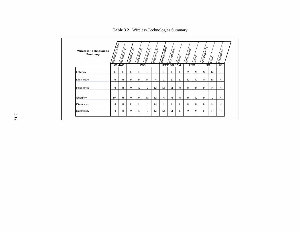
Table 3.2. Wireless Technologies Summary
Wireless Technologies Summary
IEE
E 8
02.1
6-20
04IE
EE
802
.16e
IEE
E 8
02.1
1a
IEE
E 8
02.1
1b
IEE
E 8
02.1
1g
IEE
E 8
02.1
1n
Wire
less
HA
RT
ISA
100
.11a
Zig
bee
GP
RS
/ED
GE
1xR
TT
HS
PD
A/U
MTS
EVD
O
LTE
/HS
PA
+
3GWiMAX WiFi IEEE 802.15.4 2.5G 4G
Latency L L L L L L L L L M M M M L
Data Rate H H H H H H L L L L L M M H
Resilience H H M L L M M M M H H H H H
Security H* H M M M M H H M H L H L H
Distance H H L L L M L L L H H H H H
Scalability H H M L L M M M L M M H H H
3GWiMAX WiFi IEEE 802.15.4 2.5G
3.13
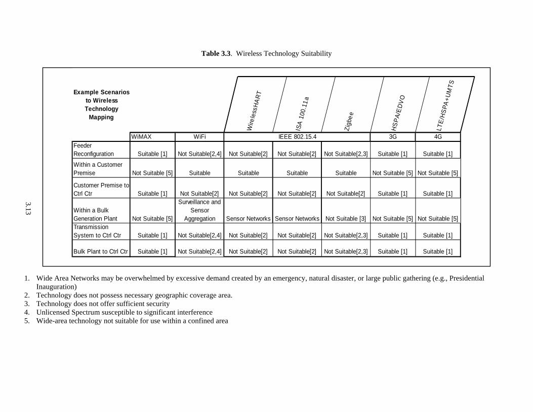
Table 3.3. Wireless Technology Suitability
1. Wide Area Networks may be overwhelmed by excessive demand created by an emergency, natural disaster, or large public gathering (e.g., Presidential
Inauguration) 2. Technology does not possess necessary geographic coverage area. 3. Technology does not offer sufficient security 4. Unlicensed Spectrum susceptible to significant interference 5. Wide-area technology not suitable for use within a confined area
Example Scenarios to Wireless Technology
Mapping
Wire
less
HA
RT
ISA
100
.11
a
Zig
bee
HS
PA
/ED
VO
LTE
/HS
PA
+U
MT
S
IEEE 802.15.4WiMAX WiFi 3G 4GFeeder Reconfiguration Suitable [1] Not Suitable[2,4] Not Suitable[2] Not Suitable[2] Not Suitable[2,3] Suitable [1] Suitable [1]
Within a Customer Premise Not Suitable [5] Suitable Suitable Suitable Suitable Not Suitable [5] Not Suitable [5]
Customer Premise to Ctrl Ctr Suitable [1] Not Suitable[2] Not Suitable[2] Not Suitable[2] Not Suitable[2] Suitable [1] Suitable [1]
Within a Bulk Generation Plant Not Suitable [5]
Surveillance and Sensor
Aggregation Sensor Networks Sensor Networks Not Suitable [3] Not Suitable [5] Not Suitable [5]Transmission System to Ctrl Ctr Suitable [1] Not Suitable[2,4] Not Suitable[2] Not Suitable[2] Not Suitable[2,3] Suitable [1] Suitable [1]
Bulk Plant to Ctrl Ctr Suitable [1] Not Suitable[2,4] Not Suitable[2] Not Suitable[2] Not Suitable[2,3] Suitable [1] Suitable [1]
IEEE 802.15.4
4.1
4.0 Fault Tolerance
Fault tolerance will be a major challenge in modernizing the electric power system. This state of affairs will exist because the modernization of the system will add a significant amount of equipment, and all of it is capable of experiencing faults. Although our concern in this report is wireless communications, we must consider the question for the power system as a whole, as well as for the communication scheme.
First, to introduce some concepts, let us look at just the power system. The existing power delivery system is fault tolerant to different degrees in its different parts. A fault in the transmission system is detected (by the relaying system) and cleared. The effect may not be observed by any customers. In the jargon of fault tolerance, the fault is masked. The transmission system is highly interconnected: its architecture provides fault tolerance by redundancy.
The distribution system is less fault-tolerant. Because the economics have not typically justified interconnected networking, distribution system faults are cleared (by the relaying system) and thereby contained. The architecture is thus one of fault detection and containment, as is the architecture of the transmission system, but the lack of redundant connections means that the effects of the containment will be seen by the customers. The fault is not masked.
Now let us look at the impact of making the system smart. The added control and communication systems that will comprise the smart grid will be subject to both hardware and software faults. As with the power system, the architecture of the overall system must be designed to cope with these faults. Fault containment is as possible in the communication and control system as it is in the power system. The details of how communication system faults are contained should be evaluated when considering the modernization of the electric power system.
The wireless communication systems we have looked at in this report generally have a measure of fault tolerance in their overall design, because (for example) packets can be routed differently if a node has failed (or is attacked). Some systems are very effective at masking faults in this way. For a system with this attribute, a fault detection and reporting system should be considered an essential part of the design, so that faults do not accumulate unnoticed to the point that they can no longer be contained.
There are several different aspects to the fault-tolerance problem. Hermann Kopetz of the University of Vienna identifies five separate areas of consideration [Kopetz 2004]:
1. The Reliability Challenge: All electronic parts have a statistical chance of failure that together give a reliability figure for systems that can be estimated with fair accuracy. An essential first step in the process of designing around these statistics is that the communication system architecture be selected to give a system that is more reliable than its components. It is then necessary that the system is capable of being tested for its fault tolerance—with a high-reliability architecture, testing for reliability may not be practical.

4.2
2. The Abstracting Problem: A single-line diagram is an abstract representation of a power system that can be used to understand the way the parts are interconnected.1 Some analogous abstraction is needed for the communication and control aspects of the power system. In order to design the appropriate scheme for fault tolerance, it must be abstracted in a way that it can be thoroughly understood. Only then can a fault-tolerance algorithm be designed, and the fault-tolerance scheme be fairly modeled.
3. The Hardware Fault problem. The problem is similar to that of the reliability challenge, but the hardware fault is caused by something other than a statistically estimable component failure. In the electric power system, possible failure mechanisms include bullets, lightning strikes, and environmental problems. Some failures may be temporary, others permanent.
4. Design Faults: Perhaps all that can be done to guard against design faults is to divide the system into modules that can be separately designed and tested.
5. Human Failures: Human failures are unavoidable, but perhaps they can be rendered less impactful in an electric power system that is more autonomously operated.
With these factors in mind, a fault hypothesis must be developed. This hypothesis states the types and number of faults that the system must be designed to tolerate. (These are called covered faults.) The fault hypothesis defines what is expected (or allowed) to fail. There will always be faults that are not covered by the fault-tolerant design: nevertheless, the effect of these faults should be considered in the overall system evaluation.
The amount of effort that should go into designing and testing for fault tolerance must depend on the nature of the system being controlled.2 For a part of the power system that is presently unmonitored (which typically means most of the distribution system), it would be unacceptable for the addition of “smartness” to decrease the availability of power! Therefore, the fault hypothesis (for the communication and control scheme) must be carefully considered.
There are several considerations.
What is the minimum unit of failure being considered? Is it loss of a message or loss of a node?
If redundancy is being used, are the redundant entities guaranteed independent and guaranteed synchronized?
What are the failure modes? Will a transmitter go pathological and jam all its neighbors?
How frequently will there be failures? Can they be repaired quickly enough that they are independent, or can one fault lead to another?
Does the response to a temporary failure have different needs from the response to a permanent one?
1 At a higher level of abstraction, a cloud is a representation that does not disclose the details of interconnection. The cloud seems first to have been used in the world of communications to represent what was called the “ATM fabric.” The same representation has been used as a high-level abstraction for a power delivery system in which only the things connected to the cloud (generators, loads, storage) are relevant. 2 Existing controls in the power system are highly reliable. The case could be made, nevertheless, that their operation sometimes falls short of expectations. The blackout of August 14, 2003 was caused in part by a lack of awareness of the system situation on the part of First Energy system operators. Their software was faulted, and they were not made aware of that condition.

4.3
How will failures be detected and reported? Is error detection based on the system architecture or on an application? Will both temporary and permanent faults be reported?
What is the appropriate response? What do you want the system to do when a covered fault is detected?
What do you want the system to do when a non-covered fault is detected?
One strategy for fault tolerance following the detection of a fault in the communication and control system (for example, when the communication system goes “off the air”) would be for the power system to revert to the previous “dumb” state. While this is a reasonable philosophy, it will require careful implementation, as the initial (and immediate) action that may be required for a covered fault may depend crucially on the system state at the time of the fault. Thus, knowledge of the system state may be an essential prerequisite to choosing the appropriate fault response.
When the fault-tolerant design (or evaluation) process is complete, the system can be considered safe to deploy. A documented argument of this safety case might be needed—for example, for a vendor to convince a utility that the vendor’s product is workable.
There is no single right solution for the communications for the electric power system. When we consider the smart system in particular, we observe that there is no single definition of the smart system, and whatever is understood by the term today will certainly evolve as the field moves forward. Fault tolerance is an important (and presently under-represented) aspect of the electric power system architecture.
5.1
5.0 Recommendations
5.1 Recommendations for Implementers/Utilities
The implementers of new communication technologies in the electric power system are faced with a wide array of choices in equipment, wired and wireless network technologies, and architectures. At the same time, the implementers face a variety of claims by vendors who are doing their best to win a sales contract. One of the main goals of this document is to inform the implementers such that they can ask the right questions to their vendors. In this section, we will reiterate our recommendations.
1. Security-related recommendations:
a. Security Policy: The implementers must establish a security policy for their electric power system implementations. This security policy must be reviewed by experts, and once adopted, it must be followed with no exceptions. A typical way for an adversary to gain access to any organization is to find a device that is the weak link and use that device as a bridge to gain access. Having no exceptions to the security policy reduces the chance of having a weak link in the deployment. The electric power system security policy must include both physical and cyber security. The North American Electric Reliability Corporation Critical Infrastructure Protection specifications are a good place to start when formulating an organizational security policy.
b. Encryption and authentication for wireless communications: We recommend that the implementers always use authentication for any data that is sent over a network. While Wi-Fi, WiMAX, IEEE 802.15.4, and cellular networks provide link layer authentication and encryption, we recommend that an additional application layer authentication mechanism be used at all times to prevent message forging attacks. Any encryption or authentication algorithm is only as good as the key that is being used. Avoid use of pre-shared or static keys. If an equipment provides configuration for only a static key, or a very limited capability of changing keys (for example, only two key slots), it should not be used in an electric power system deployment. Any protocol being used in an electric power system deployment must include dynamic key provisioning. This is especially true for wireless links. Strong encryption algorithms must be used.1 If a nonce is being used, then this nonce must be unpredictable or preferably generated randomly. We highly recommend using the Advanced Encryption Standard (AES) for encryption and message integrity. For Wi-Fi deployments, the Robust Security Network Architecture (further described in Section A.2.3) must be observed. This includes use of AES-CCMP for protecting data traffic and IEEE 802.1X for authentication and network access. For Wi-Fi deployments, the implementers should strongly consider the use of management frame protection (even if it is vendor proprietary) to prevent denial of service attacks.
c. Mutual authentication for wireless networks. Wireless networks by their nature are vulnerable to man-in-the-middle (MITM) attacks. Using a mechanism that uses mutual authentication while granting access to the network can largely prevent MITM attacks. We highly recommend use of Internet Engineering Task Force standard Extensible Authentication Protocol (EAP) for authentication and use of EAP-TLS, EAP-TTLS, or EAP-SIM. Both EAP-TLS and EAP-TTLS use client and server certificates to perform mutual authentication.
1 FIPS 140-2 Annexes A-D contain a listing of currently approved security algorithms.
5.2
d. Periodic vulnerability assessments. We recommend that implementers conduct periodic vulnerability assessments of their electric power system deployments. This means that their system deployment must be designed such that a vulnerability assessment can be conducted without causing service outages to their customers. The vulnerability assessment must include active scans of equipment connected to the electric power system.
e. Pairing a smart-system device with a user account. In high-density housing where multiple smart meters and multiple customers may be present, the implementers must use a mechanism to securely pair a smart-system device (for example, a clothes dryer) with the customer’s smart meter and account.
f. For Wi-Fi deployments, we recommend use of a controller-based Wi-Fi network architecture. The controller-based architectures provide the implementers with ability to collect and aggregate wireless network information from many access points and make it easier to detect unauthorized access and shut down rogue access points in the wireless network.
2. Wide-area Wireless Networks. WiMAX and 3G/4G cellular networks provide two alternatives for wide-area coverage for the electric power system. WiMAX and 4G (LTE) cellular networks have similar data rates, range, and security properties as described in Appendix A. Due to the popularity of cellular networks and the associated economies of scale that come with a large number of subscribers, we expect 4G cellular to be cheaper and more widely available than WiMAX. Another consideration for implementers should be the implementation and operational costs of the wireless network. This is especially true for wide-area wireless networks. Based on our research, the capital expenditures to deploy such wireless networks are surpassed by at least a factor of 2 to 1 by the ongoing operational expenditures needed to maintain them [Pyramid Research 2007; Giles et al. 2004]. We recommend that smart system implementers consider partnering with existing wireless network carriers before deciding to deploy their own wireless infrastructure for wide-area coverage. If a public wireless network is used, electric power system data can be logically separated by means of a virtual private network as we describe in Section 6. Finally, we consider IEEE 802.11 (Wi-Fi) mesh networks unsuitable for obtaining wide-area coverage for the electric power system mainly because of unpredictable latencies and the use of unlicensed spectrum.
3. Home Area Networks. For home area networks, both Wi-Fi and IEEE 802.15.4 based networks are suitable choices. ZigBee, WirelessHART, and ISA100.11a all utilize radios based on the IEEE 802.15.4 standard and are designed specifically for low data rate applications. We describe IEEE 802.15.4 wireless networks in detail in Section A.3. ISA100.11a and WirelessHART are especially robust with respect to interference from other devices and can support many devices operating in the same geographic area. All of these networks are suitable for electric power system communications within the home for smart system deployments. The implementers may choose to use the IEEE 802.15.4 based protocols such as ZigBee for use within the home in order to avoid interference from widely available Wi-Fi networks.
4. Wireless Sensor Networks. For wireless sensor networks that may be used in substations and generation plants, we recommend using either WirelessHART or ISA100.11a. Both of these wireless networks provide strong security including mutual authentication to prevent MITM attacks. They support low-latency communications. The radios are robust thanks to the use of frequency-hopping and direct sequence spread spectrum modulation, which minimizes the impact of interference. For physical security applications that require high data rates such as video surveillance, we recommend
5.3
using a Wi-Fi network with AES-CCMP encryption and authentication. If a Wi-Fi network is being used, we recommend using WPA2 in enterprise mode with mutual authentication (see Section A.2.3 for details on Wi-Fi security).
5. Fault tolerance and equipment lifecycle related recommendations.
a. Contingency planning and risk economics. The implementers must be aware of the behavior of their wireless communication networks under conditions such as a natural disaster. For example, if using a public cellular network, data may get delayed during a natural disaster. This is not a big problem for meter reading, but for control traffic, such a delay may be unacceptable. A thorough analysis of risk versus benefit must be performed to identify critical areas where use of a public or private wireless network may be unsuitable.
b. Scalability. Scalability is a key requirement of the electric power system. Any chosen wireless network technology must be analyzed for scaling behavior. For example, while a particular wireless network can accommodate hundreds of thousands of devices, can it successfully bring all these devices online simultaneously after a network failure? How does it recover from a drastic outage? The network performance must degrade gracefully when under duress and recover without operator intervention when conditions improve.
c. Lifecycle management for electric power system equipment. The firmware and software that runs on the devices connected to the electric power system will need to be upgraded periodically to enhance both security and functionality. The implementers must insist on using equipment that can be upgraded without causing loss of service to their customers. The firmware upgrade process must use a cryptographically secure mechanism to verify that software is authentic and has not been altered. The equipment must be able to recover from a failed firmware upgrade without requiring a manual intervention.
d. Fault recovery and diagnostics. Devices connected to the electric power system and that run software must have a capability to retrieve diagnostic information such as the current status, memory usage, network and interrupt counters, and physical access logs. Additionally, implementers should insist on devices having a hardware watchdog capability such that if the device becomes non-responsive, the software will be rebooted automatically. Upon a software or hardware fault, the devices must be able to upload the “core dump” to a centralized server for further analysis. The analysis must be performed to detect tampering or denial of service (DoS) attempts by an adversary.
e. Disconnected operation capability. One of the challenges identified in a smart grid trial performed on the Olympic Peninsula in Washington by the Pacific Northwest National Laboratory was the communication failures between the HAN and the utility network. All smart system HAN devices must be able to function in a disconnected mode for a period to be determined by their utility. The smart system device must be able to reconnect and synchronize state with the utility network without causing a service outage. As micro-system deployments become more commonplace and both distributed energy generation and storage (e.g., plug-in hybrids) are integrated into the smart system, the disconnected operation capability will become more important.
5.4
5.2 Recommendations for Equipment Manufacturers
The equipment manufacturers for the electric power system are in a unique position to ensure that their equipment is reliable, scalable, and secure before it has shipped. While an implementer or a national testbed can perform a vulnerability assessment after the equipment has shipped, a defect found in this stage may result in deployment delays and cost overruns. By adopting good engineering practices, the equipment manufacturers have the capability to prevent problems in the field.
We recommend use of software engineering best practices such as automated unit and regression tests, code reviews, security reviews, and vulnerability assessments. We also recommend not relying on proprietary (non-standard) encryption and authentication algorithms and key distribution protocols. For wireless equipment, a suitable credential provisioning process should be developed to enable an implementer to easily use mutual authentication for granting network access. If possible, software vulnerability scanning tools should be used to scan the source code for defects such as buffer overflows, missing packet type and length checks, etc.
Harden devices against DoS attacks. For example, if a smart meter has a wireless network interface that is rated at 100 Mbps, then the manufacturers must test the smart meter at a rated traffic of 100 Mbps at the smallest and largest packet sizes that are supported. The device cannot crash, lose context, or become non-responsive when receiving packets at a rate that its network interface is capable of receiving. Whenever possible, a hardware watchdog mechanism must be installed to reboot a device that has become non-responsive. The hardware watchdog should save as much of the software context as possible to enable the manufacturer to diagnose the problem. The manufacturer must implement a mechanism to retrieve such a “core dump” from the equipment in a secure and automated manner.
All devices (and especially wireless devices) must be able to function when they are temporarily disconnected from the utility networks. The manufacturers must put enough storage (to be defined by their customers) to log information and logic to realize that the communication channel has failed. A recovery mechanism to resynchronize the device with the utility network must be defined.
5.3 Recommendations for Policymakers
The electric power system is a complex collection of devices and networks. Actions can be taken at the policy level to help smooth out the deployment of wireless communications technology in the electric power system while reducing interoperability and security risks. There have already been significant efforts concentrating on both research and deployment of “smart” technologies for the electric power system. In addition to these existing efforts, we have identified the following areas for further research:
1. National electric power system interoperability and vulnerability testbeds. The smart system deployments, which are a crucial part of modernizing our electric power system, are evolving rapidly. There are many equipment vendors. The equipment vendors come from varied backgrounds and have different perspectives and varying levels of experience in developing highly interconnected and dynamic systems. We propose that further work should be conducted to form one or more interoperability and vulnerability testbeds for smart system deployments. These testbeds will be sites for vendors and utilities to bring equipment and conduct wide-scale deployment and vulnerability tests in a large smart system network. The testbeds will also provide an ideal environment to come up with cookbook type recipes for implementers of smart system technology such that they know what
5.5
works and what does not. Another benefit of such a testbed is to establish a combined pool of resources in a large facility to prevent replication of effort and investment in many smaller testing projects.
2. Development of wireless communication cookbook recipes for suitable electric power system deployments by stakeholders. One of the challenges in deploying data communication networks is the number of variations in configuration and connectivity that are implemented. This is especially true for data communication networks where a typical networking device may have thousands of different configuration settings. A technique commonly used by network engineers is to develop blueprints or recipes of known, working configurations and deploy these repeatedly. These network recipes also serve to upper-bound the number of variations so that security analysts can perform thorough vulnerability assessments and qualify the security properties of the recipes. We propose that policymakers encourage development of such communication network recipes for the electric power system in a cookbook by a joint effort of vendors, utilities, and national laboratories. These recipes will define deployment configurations (for example, which encryption algorithms to run), security policies, and recommended staff roles (for example, having a security office responsible for defining and maintaining security policy). Especially for utilities that may not have dedicated staff with the necessary networking experience, we expect an “electric power system cookbook” to be very useful.
3. Development of open-source source code vulnerability scanning tools. While there are excellent open-source/free tools for external (black box) testing of networking devices such as nmap, dsniff, and airpwn, good open-source tools for internal software vulnerability analysis that can be used during development do not exist. Research and development of software vulnerability scanning tools that can be used for firmware, basic input/output system (BIOS), and low-level device driver implementations is required. The tools must support embedded systems that use microcontrollers in addition to general-purpose processors. Such source code vulnerability scanning tools, developed by the open-source community, will allow both small and large vendors that supply equipment to the electric power system to validate their software by programmatic analysis and not rely solely on external vulnerability scanners. The benefit of these tools is to increase the reliability of devices connected to the electric power system.
6.1
6.0 References
Giles T, J Markendahl, J Zander, P Zetterberg, P Karlsson, G Malmgren, and J Nillsson. 2004. “Cost Drivers and Deployment Scenarios for Future Broadband Wireless Networks: Key Research Problems and Directions for Research.” In Proceedings of the IEEE Vehicular Technology Conference 04, pp. 2042 – 2046, Milan, Italy.
Kopetz H. 2004. “Twelve Principles for the Design of Safety-Critical Real-Time Systems.” Keynote speech at the Workshop on Parallel and Distributed Real-Time Systems 2004 (WPDRTS04), Santa Fe, New Mexico.
Petersen S, B Myhre, et al. 2008. “A Survey of Wireless Technology for the Oil and Gas Industry.” In Proceedings of the SPE Intelligent Energy Conference and Exhibition, Amsterdam, The Netherlands, February 25-27, 2008.
Petersen S, S Carlsen, and A Skavhaug. 2008. “Layered Software Challenge of Wireless Technology in the Oil & Gas Industry.” In Proceedings of the 19th Australian Conference on Software Engineering, pp. 37-46. IEEE Computer Society, Washington, D.C.
Pyramid Research, Inc. 2007. “Demystifying Opex & Capex Budgets—Feedback from Operator Network Managers.” Accessed December 10, 2009 at http://www.researchandmarkets.com/reportinfo.asp?report_id=448691, 2007.
Schweppe FC, RD Tabors, JL Kirtley, HR Outhred, FH Pickel, and AJ Cox. 1980. “Homeostatic Utility Control.” IEEE Transactions on Power Apparatus and Systems, PAS-99(3):1151 – 1163.

Appendix A
A.1
Appendix: A Survey of Wireless Communications Technologies
Many wireless communication technologies are applicable to the electric power system. In this appendix, we present an overview of WiMAX, Cellular, Wi-Fi, and 802.15.4 technologies and highlight their strengths and weaknesses.
A.1 IEEE 802.16 d/e WiMAX
WiMAX stands for Worldwide Interoperability for Microwave Access. It is an Institute of Electrical and Electronics Engineers (IEEE) standard identified by the designation of 802.16-2004 and 802.16e-2005. IEEE 802.16-2004 standard focuses on fixed wireless applications such as wireless Digital Subscriber Line (DSL), and the IEEE 802.16e standard focuses on mobile broadband access. WiMAX provides fixed (wireless local loop), portable, and mobile high data rate wireless service at speeds of up to 72 Mbps and distances up to 6 miles. Line-of-sight is not a requirement, although early versions of the IEEE 802.16 standards were line-of-sight only. While WiMAX has a reach of up to 6 miles, the data rates at the edge of this reach may be significantly lower than 72 Mbps. Recent studies [Durantini et al. 2008; Mach and Bestak 2007] have indicated that the actual link performance of WiMAX at 5 miles drops to about 1.8 Mbps for reserved traffic. WiMAX first-hop latencies on currently deployed networks are on the order of 100 ms. It is also important to note that the radios for 802.16-2004 and 802.16e are not compatible because 802.16-2004 uses orthogonal frequency division multiplexing (OFDM) with 256 sub-carriers, while 802.16e uses Scalable OFDM with Fast Fourier Transform sizes (subcarriers) of 128, 512, 1024, and 2048 for the frequency domain to time domain transition.
In this appendix, we will provide an overview of both versions of the WiMAX standard.
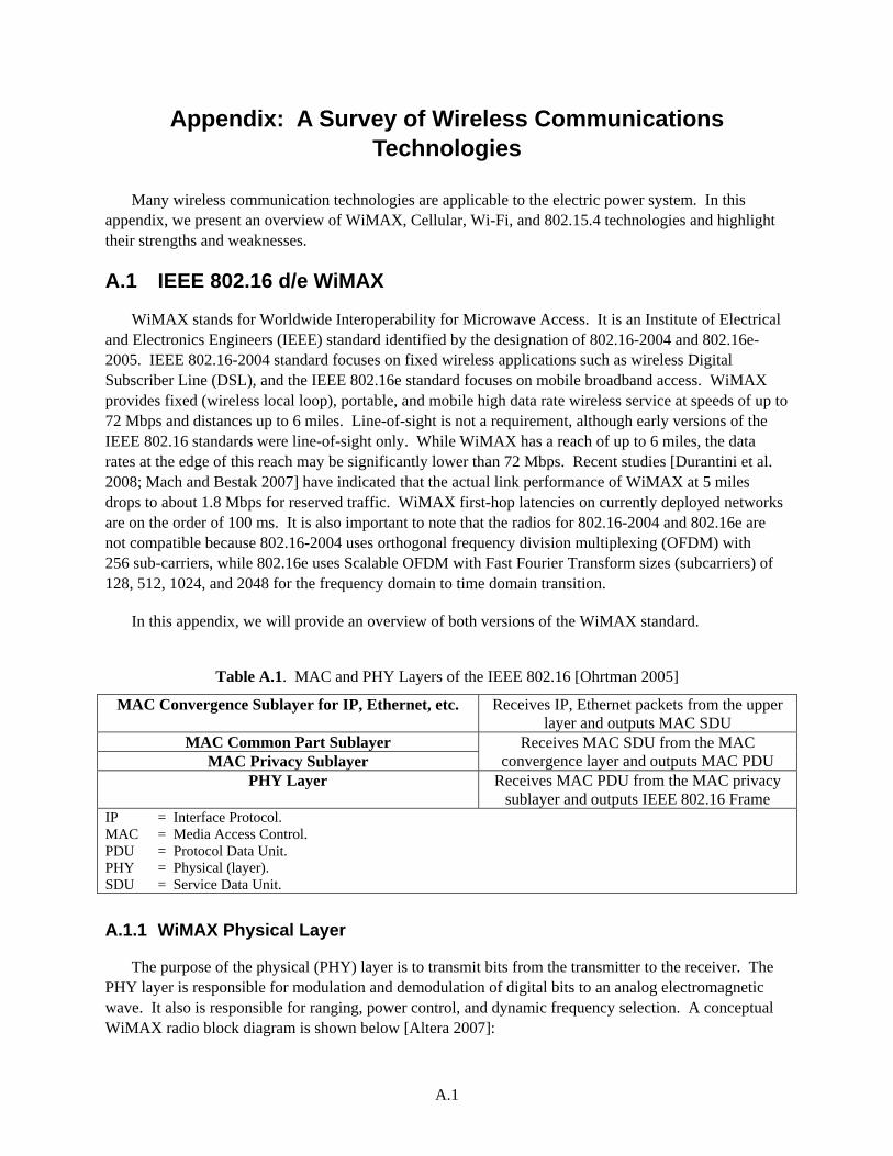
Table A.1. MAC and PHY Layers of the IEEE 802.16 [Ohrtman 2005]
MAC Convergence Sublayer for IP, Ethernet, etc. Receives IP, Ethernet packets from the upper layer and outputs MAC SDU
MAC Common Part Sublayer Receives MAC SDU from the MAC convergence layer and outputs MAC PDU MAC Privacy Sublayer
PHY Layer Receives MAC PDU from the MAC privacy sublayer and outputs IEEE 802.16 Frame
IP = Interface Protocol. MAC = Media Access Control. PDU = Protocol Data Unit. PHY = Physical (layer). SDU = Service Data Unit.
A.1.1 WiMAX Physical Layer
The purpose of the physical (PHY) layer is to transmit bits from the transmitter to the receiver. The PHY layer is responsible for modulation and demodulation of digital bits to an analog electromagnetic wave. It also is responsible for ranging, power control, and dynamic frequency selection. A conceptual WiMAX radio block diagram is shown below [Altera 2007]:
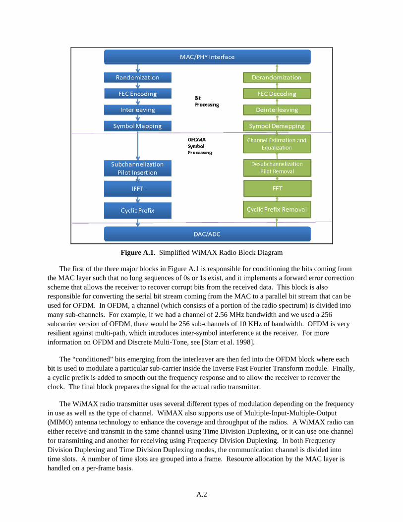
A.2
Figure A.1. Simplified WiMAX Radio Block Diagram
The first of the three major blocks in Figure A.1 is responsible for conditioning the bits coming from the MAC layer such that no long sequences of 0s or 1s exist, and it implements a forward error correction scheme that allows the receiver to recover corrupt bits from the received data. This block is also responsible for converting the serial bit stream coming from the MAC to a parallel bit stream that can be used for OFDM. In OFDM, a channel (which consists of a portion of the radio spectrum) is divided into many sub-channels. For example, if we had a channel of 2.56 MHz bandwidth and we used a 256 subcarrier version of OFDM, there would be 256 sub-channels of 10 KHz of bandwidth. OFDM is very resilient against multi-path, which introduces inter-symbol interference at the receiver. For more information on OFDM and Discrete Multi-Tone, see [Starr et al. 1998].
The “conditioned” bits emerging from the interleaver are then fed into the OFDM block where each bit is used to modulate a particular sub-carrier inside the Inverse Fast Fourier Transform module. Finally, a cyclic prefix is added to smooth out the frequency response and to allow the receiver to recover the clock. The final block prepares the signal for the actual radio transmitter.
The WiMAX radio transmitter uses several different types of modulation depending on the frequency in use as well as the type of channel. WiMAX also supports use of Multiple-Input-Multiple-Output (MIMO) antenna technology to enhance the coverage and throughput of the radios. A WiMAX radio can either receive and transmit in the same channel using Time Division Duplexing, or it can use one channel for transmitting and another for receiving using Frequency Division Duplexing. In both Frequency Division Duplexing and Time Division Duplexing modes, the communication channel is divided into time slots. A number of time slots are grouped into a frame. Resource allocation by the MAC layer is handled on a per-frame basis.
A.3
The WiMAX PHY layer uses state-of-the-art radio techniques to increase range and throughput. The downside of this is that the radios are complex, use significant power, and are much more expensive than IEEE 802.11 (Wi-Fi) radios that offer similar throughput but at a much shorter range. Even at equivalent complexity, the Wi-Fi radios will be significantly cheaper because of the larger volume of Wi-Fi shipments.
A.1.2 WiMAX MAC Layer
The WiMAX MAC layer controls when and how the wireless shared channel is accessed. A WiMAX network consists of gateways to other networks such as the internet, base stations (BS), and subscriber stations. The WiMAX wireless channel operates with a central BS that uses sectorized antennas to cover different geographic quadrants. For example, when 120-degree coverage antennas are used, the WiMAX BS is said to have three sectors. The sectorized antennas increase the number of users that can be serviced by a BS. In WiMAX, the BS is responsible for allocating bandwidth to all subscribers in both the uplink and the downlink. The WiMAX MAC allocates time slots out of a frame. In Time Division Duplexing mode, a frame is divided into downlink1 (DL) and uplink slots. In Frequency Division Duplexing mode, there is a channel used for downlink and a second paired channel used for uplink communications. Note that because WiMAX does not support direct peer-to-peer (ad hoc) transmission, there is no contention for downlink transmissions at the MAC layer. The WiMAX MAC allocates slots using a scheduling algorithm2 and communicates this to the subscribers. The uplink slots are requested by the subscribers and scheduled by the BS. Therefore, WiMAX is a collision3-free technology. While there may be competition for resources, because the MAC is connection-oriented, there cannot be any collisions in the air. The benefit of this is that as the number of users that share the channel increases, unlike 802.11 networks, the channel throughput stays relatively stable because none of the bandwidth is wasted for collisions. 802.11 media access layer is discussed in this report in Section A.2.2.
WiMAX supports five classes of service:
Unsolicited Grant Services: Unsolicited Grant Services is designed to support constant bit rate services. A subscriber station that uses Unsolicited Grant Services will make a single request and get a reserved allocation for the duration of the connection.
Real-Time Polling Services: Real-Time Polling Services supports time-sensitive, variable bit rate traffic such as compressed video and voice communications.
Non-Real-Time Polling Services: Non-Real-Time Polling Services is designed to support services that require variable size data allocation on a regular basis.
Best Effort (BE) Services: BE services are used for internet traffic.
Extended real-time variable rate service: This service is defined in IEEE 802.16e-2005 and is suitable for applications that have variable data rates but still require minimum guaranteed data rate and delay.
1 Downlink and uplink directions are defined from the perspective of a base station. Traffic being sent by the base station to subscribers is referred to as downlink. Traffic being sent by the subscribers to the base station is referred to as uplink. 2 WiMAX MAC scheduling algorithm is not specified in the IEEE 802.16 standards and is vendor specific. 3 A collision in a wireless network happens when two stations try to transmit at the same time. The transmissions effectively jam each other, preventing correct reception of information.
A.4
WiMAX Security in the MAC Layer
Security functions for WiMAX are handled within the MAC Privacy Layer. The privacy layer supports both AES (Advanced Encryption Standard) [FIPS 197 2001] and 3DES (Triple Data Encryption Standard) [ANSI X9.52 1998]. It is highly likely that most implementations of WiMAX will support AES with key strengths of 128 or 256 bits. The key used for encryption is refreshed periodically to decrease the likelihood of an attacker eavesdropping on the communication. The key refresh period is configurable by the WiMAX network operator. WiMAX defines the Privacy and Key Management protocol for securely transferring keying material between the BS and the subscriber in IEEE802.16e-2005. Privacy and Key Management protocol uses Extensible Authentication Protocol (EAP), X.509 certificates, and RSA public key encryption algorithms to exchange symmetric cipher keys between the BS and the subscriber module.
WiMAX can authenticate devices and users using the Internet Engineering Task Force (IETF) EAP [Internet Engineering Task Force 2004]. Specifically, EAP-TLS, EAP-TTLS, and EAP-SIM methods are supported. Devices and users can be authenticated via username/password, Subscriber Identity Module (SIM) cards, or X.509 digital certificates. If EAP-TLS, EAP-TTLS, or EAP-SIM is used, the subscribers and network can use mutual authentication. Mutual authentication is important because it prevents man-in-the-middle (MITM) attacks.
The integrity of over–the-air control messages is protected by using a message digest4 scheme such as HMAC-MD5 or AES-CMAC.
WiMAX Common Sublayer as shown in Table A.1 defines the base part of the WiMAX MAC. Specifically, the common sublayer defines the MAC PDU. WiMAX defines native support for transport of both IP and Ethernet. WiMAX convergence layers define how IP packets and Ethernet frames are fit into WiMAX PDUs. The convergence layers also specify how WiMAX handles quality of service (QoS) and bandwidth allocation with respect to the upper layer protocol.
A.1.3 Further Discussion on WiMAX Security
In this section, we will focus on the security threats that apply to WiMAX networks [Andrews et al. 2007; Barbeau 2005; Naseer et al. 2008; Xu et al. 2006]. These security threats can be divided into two categories: PHY layer threats and MAC layer threats.
PHY Layer Threats
Because WiMAX uses wireless communications and is specifically designed to work in non-line-of-sight environments, it is susceptible to attacks that exploit the open nature of RF communications. The PHY layer of WiMAX is susceptible to jamming, scrambling, and denial of service (DoS) attacks via the RF medium.
Jamming is performed by an adversary that can output a significant amount of power in the WiMAX frequency band via a radio transmitter. The jamming signal overwhelms the radio receiver and acts as
4 A message digest is a cryptographic checksum that is computed for the message. It allows the recipient to verify that the message has not been tampered with.
A.5
additional noise thereby reducing the signal-to-noise ratio and making communication difficult if not impossible. This type of broad spectrum jamming is not unique to WiMAX networks. The best defense against a broad spectrum jammer is to use direct-sequence spread spectrum technology. Because this is unavailable in WiMAX, an operator can try increasing the signal power or using high-gain directional antennas that improve the signal strength. However, against a determined adversary, these measures have limited value.
Scrambling is performed by an adversary that has WiMAX receive and transmit equipment and has access to the uplink and downlink frame structures and transmission scheduling. The adversary will try to use bursts of power to disrupt either certain frames (management, belonging to a certain user, broadcast, etc.) or even frame headers. This attack can be difficult to detect and is hard to defend against. However, due to the equipment requirements, we believe this attack to be lower risk than jamming.
An adversary that has access to WiMAX receive and transmit equipment can also use this equipment to perform a DoS attack on subscribers, essentially causing them to waste their power on receiving unwanted frames. Note that message integrity checks (MICs) are not useful against this type of an attack because the message digest computation to validate whether the packet is wanted or unwanted is one of the most power-consuming operations that a receiver may perform. For the electric power system, because the devices have access to wired power, this attack is less of a nuisance especially when compared to the same attack on mobile devices such as notebook computers or handsets.
MAC Layer Threats
WiMAX MAC layer implements a complex protocol that includes many moving parts. We will focus our discussion of the security threats against the WiMAX MAC in two main areas: Authentication and Management Frame spoofing. To understand MAC layer threats, it is useful to know how a subscriber station gets onto a WiMAX network.
A WiMAX subscriber enters the WiMAX network using the following process:
1. Scan downlink channels and synchronize with a base station.
2. Acquire downlink and uplink descriptions to determine available uplink channels.
3. Perform WiMAX Ranging. The basic and primary management connections are assigned during the ranging process. Because ranging happens before authorization credentials are exchanged, the traffic is unencrypted. The basic and primary management connections can optionally support message integrity checks.
4. Perform capability negotiation over the basic connection.
5. Complete authorization, authentication, and key establishment over the primary connection.
6. Establish a fully encrypted secondary management connection after the registration is completed.
As can be seen from the discussion above, a WiMAX subscriber station has three ongoing management connections at any given time. There are several points we would like to highlight:
The Ranging process uses frames that do not have message integrity checks or encryption.

A.6
The primary and the basic management connections do not have encryption capabilities; however, with IEEE802.16e-2005, they can at least support message integrity checks. An OMAC (one-key message authentication) should be used to perform the message integrity checks on the primary and basic management connections because it offers replay5 protection [Iwata 2009].
The authentication, authorization, and key establishment process allows for device-list, RSA/X.509 certificate-based and EAP-based authentication.
Unfortunately, when WiMAX network operators choose not to use EAP-based mutual authentication, the subscriber stations are vulnerable to MITM attacks of various kinds [Barbeau 2005; Naseer et al. 2008; Xu et al. 2006]. Without mutual authentication, the base station will be able to verify the subscriber identity, yet the subscriber has to trust that the base station is authentic. In other words, a third party can intercept the communication and pretend to be a base station. This problem also applied to IEEE802.11-based wireless local area networks but was fixed with the introduction of IEEE802.11i security framework.
There are several WiMAX management frames, including RNG-REQ, RNG-RESP (for ranging); MOB_NBR-ADV (mobile neighbor advertisement); fast power control; and AUTH-INVALID frames that are not protected by message integrity checks. With degrees of varying difficulty, an adversary can forge these frames and cause either wide-scale or per-subscriber service outages.
The WiMAX MAC layer provides confidentiality and integrity services for data packets by means of 3DES and AES as described earlier. When AES-CCM is used, both confidentiality and integrity are provided. With 3DES, only confidentiality of data is provided. Confidentiality-only modes are prone to various attacks and should not be used.
Security researchers commonly set up networking equipment in their labs to perform vulnerability analysis. WiMAX is unlike IEEE 802.11 networks. IEEE 802.11 has been widely studied because equipment is cheap and widely available. WiMAX networks require a service provider and potentially licensed equipment to test and analyze. As WiMAX becomes more ubiquitous, we expect more security vulnerabilities to emerge.
In this section, we presented an overview of the WiMAX (IEEE 802.16) wireless networking technology. We recommend that the reader obtain a copy of the IEEE802.16e-2005 or later specification and a book such as [Andrews et al. 2007] to gain a better understanding of the protocol.
5 A replay attack happens when an adversary captures a valid frame and replays the same frame at a different time to confuse the receiver and disrupt communications.

A.7
A.2 IEEE 802.11 a/b/g/n and IEEE802.11s Mesh Networks
IEEE 802.11 wireless local area networks (WLAN) are the second most successful and widely deployed wireless data networks in the world (second to only cellular networks). Unlike the cellular and WiMAX networks, the 802.11 WLANs operate solely on unlicensed spectrum at 2.4 GHz and 5 GHz. The most current standard for IEEE 802.11 is IEEE 802.11-2007 and this standard is available for free at http://www.ieee.org. There is an imminent update6 coming to this specification to add support for very high data rates (300 Mbps or more) and more range. This update is referred to as IEEE 802.11n. IEEE 802.11 Working Group is also working on IEEE 802.11s for mesh WLANs and IEEE 802.11w for management frame protection.7
IEEE 802.11 standard defines a MAC layer and a PHY layer. There are four types of PHY that are widely in use: 802.11b 2.4 GHz, 802.11g 2.4 GHz, 802.11a 5 GHz, and 802.11n (draft) 2.4 and 5 GHz PHY.
The MAC layer provides:
media access control via carrier sense multiple access/collision avoidance (CSMA/CA)
prioritization for up to eight priorities
confidentiality and integrity via encryption and message digests; reliable transport via a windowed acknowledgment mechanism
fragmentation and reassembly.
IEEE 802.11n (draft) modifies the 802.11 standard to add support for packing of multiple upper layer protocol packets into a single IEEE 802.11 frame to improve throughput.
In this section, we will present a summary of the 802.11 PHY and MAC layers. The reader is referred to the standard to obtain a detailed understanding of the 802.11 WLAN technologies.
A.2.1 IEEE 802.11 PHY
The IEEE 802.11 PHY layer has evolved from a radio that can support 1-2 Mbps to a radio that can support 300 Mbps or above with the latest IEEE 802.11n standard.8
Table A.2 presents a summary of the different PHY specifications currently in use.
6 IEEE 802.11n (draft 2.0) specification WLAN clients have been available for a few years. These clients are expected to be firmware or software upgradeable to the finished standard. 7 Proprietary management frame protection schemes exist. One vendor that offers this feature is Cisco Systems. This feature is available with clients that offer CCX v5 compatibility. 8 IEEE 802.11n standard is expected to be published by the end of 2009.
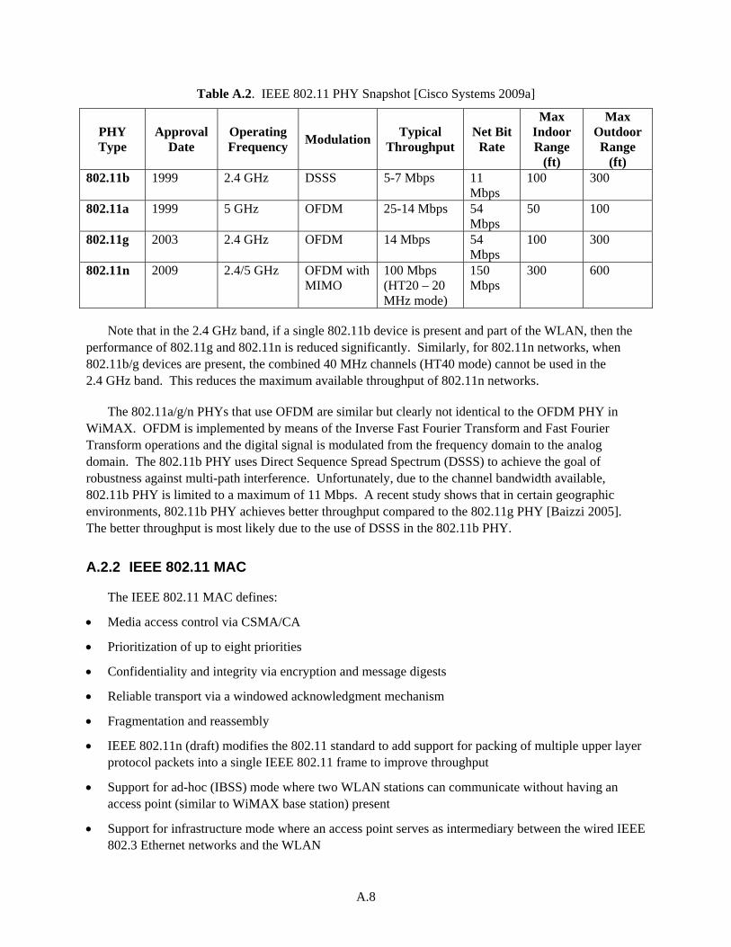
A.8
Table A.2. IEEE 802.11 PHY Snapshot [Cisco Systems 2009a]
PHY Type
Approval Date
Operating Frequency
ModulationTypical
Throughput Net Bit
Rate
Max Indoor Range
(ft)
Max Outdoor Range
(ft) 802.11b 1999 2.4 GHz DSSS 5-7 Mbps 11
Mbps 100 300
802.11a 1999 5 GHz OFDM 25-14 Mbps 54 Mbps
50 100
802.11g 2003 2.4 GHz OFDM 14 Mbps 54 Mbps
100 300
802.11n 2009 2.4/5 GHz OFDM with MIMO
100 Mbps (HT20 – 20 MHz mode)
150 Mbps
300 600
Note that in the 2.4 GHz band, if a single 802.11b device is present and part of the WLAN, then the performance of 802.11g and 802.11n is reduced significantly. Similarly, for 802.11n networks, when 802.11b/g devices are present, the combined 40 MHz channels (HT40 mode) cannot be used in the 2.4 GHz band. This reduces the maximum available throughput of 802.11n networks.
The 802.11a/g/n PHYs that use OFDM are similar but clearly not identical to the OFDM PHY in WiMAX. OFDM is implemented by means of the Inverse Fast Fourier Transform and Fast Fourier Transform operations and the digital signal is modulated from the frequency domain to the analog domain. The 802.11b PHY uses Direct Sequence Spread Spectrum (DSSS) to achieve the goal of robustness against multi-path interference. Unfortunately, due to the channel bandwidth available, 802.11b PHY is limited to a maximum of 11 Mbps. A recent study shows that in certain geographic environments, 802.11b PHY achieves better throughput compared to the 802.11g PHY [Baizzi 2005]. The better throughput is most likely due to the use of DSSS in the 802.11b PHY.
A.2.2 IEEE 802.11 MAC
The IEEE 802.11 MAC defines:
Media access control via CSMA/CA
Prioritization of up to eight priorities
Confidentiality and integrity via encryption and message digests
Reliable transport via a windowed acknowledgment mechanism
Fragmentation and reassembly
IEEE 802.11n (draft) modifies the 802.11 standard to add support for packing of multiple upper layer protocol packets into a single IEEE 802.11 frame to improve throughput
Support for ad-hoc (IBSS) mode where two WLAN stations can communicate without having an access point (similar to WiMAX base station) present
Support for infrastructure mode where an access point serves as intermediary between the wired IEEE 802.3 Ethernet networks and the WLAN
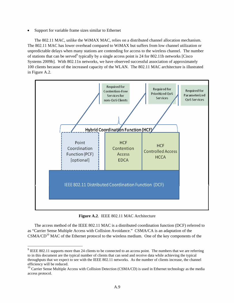
A.9
Support for variable frame sizes similar to Ethernet
The 802.11 MAC, unlike the WiMAX MAC, relies on a distributed channel allocation mechanism. The 802.11 MAC has lower overhead compared to WiMAX but suffers from low channel utilization or unpredictable delays when many stations are contending for access to the wireless channel. The number of stations that can be served9 typically by a single access point is 24 for 802.11b networks [Cisco Systems 2009b]. With 802.11n networks, we have observed successful association of approximately 100 clients because of the increased capacity of the WLAN. The 802.11 MAC architecture is illustrated in Figure A.2.
Figure A.2. IEEE 802.11 MAC Architecture
The access method of the IEEE 802.11 MAC is a distributed coordination function (DCF) referred to as “Carrier Sense Multiple Access with Collision Avoidance.” CSMA/CA is an adaptation of the CSMA/CD10 MAC of the Ethernet protocol to the wireless medium. One of the key components of the
9 IEEE 802.11 supports more than 24 clients to be connected to an access point. The numbers that we are referring to in this document are the typical number of clients that can send and receive data while achieving the typical throughputs that we expect to see with the IEEE 802.11 networks. As the number of clients increase, the channel efficiency will be reduced. 10 Carrier Sense Multiple Access with Collision Detection (CSMA/CD) is used in Ethernet technology as the media access protocol.
A.10
DCF is the virtual carrier sensing mechanism, which is a solution to the hidden terminal problem first identified and solved by Tobagi and Kleinrock [Tobagi and Kleinrock 1975]. The DCF is a mandatory component. In the rest of this section, we will summarize the operating principles of the IEEE 802.11 MAC including the QoS capabilities. The reader is referred to the IEEE 802.11-2007 specification for further information.
For a client (STA) to transmit, it first tries to sense the carrier to determine if another STA is transmitting. The CSMA/CA algorithm mandates that a minimum duration must pass after a frame transmission and a transmitting STA must wait for at least this time period before attempting to transmit. If the medium is available, then the STA will transmit. Furthermore, when a collision is detected, an STA must wait for a time period that is determined by a randomized exponential back-off algorithm. IEEE 802.11 MAC supports either individual or block acknowledgments to indicate successful reception of a frame. Because long frame sizes are supported and the probability of collision increases with the size of the frame, the 802.11 MAC implements a request-to-send (RTS)/clear-to-send (CTS) mechanism to improve efficiency. RTS/CTS-based access is more efficient due to the “virtual carrier” mechanism. When an STA requests to send a frame, it uses the RTS frame indicating the duration of transmission as a parameter. When the access point (or the receiver) receives the RTS, it transmits a CTS frame indicating that the channel is reserved for the STA that sent the RTS for the requested duration of transmission. The other terminals that are within hearing range of the access point can then assert a virtual carrier signal to the CSMA/CA algorithm and the original STA will transmit successfully. Because RTS frames are shorter than data frames, the chance of collision is minimized. The RTS/CTS mechanism also alleviates the hidden-terminal problem from CSMA/CA. Therefore, use of RTS/CTS is highly recommended.
In addition to the basic DCF function that does not support QoS or traffic prioritization, the 802.11 MAC provides for three different QoS mechanisms: Point Coordination Function (PCF), Hybrid Coordination Function (HCF) with contention-based channel access, and HCF controlled-channel access. The PCF is a polling-based mechanism that only works in infrastructure (access point) type networks and uses a polling coordinator embedded in the access point that provides for contention-free access. PCF is an optional mechanism and is not commonly supported. HCF is only supported in QoS network configuration and is mandatory for all clients that implement QoS support. HCF operates by dividing the channel access into a Controlled-Access Period and a Contention Period. In HCF mode, there are four priority access categories supporting eight levels of user priorities. The priorities are mapped according to Table 9-1 of the IEEE 802.11-2007 specification. In our experience, the HCF mechanisms are not commonly used for data. When Voice over Internet Protocol is being transmitted via WLANs, a WLAN instance is defined to segment voice from data and different channel allocations are given to the voice WLAN so that voice STAs are not starved for bandwidth.
The IEEE 802.11s specification extends the infrastructure mode such that a mesh network of 802.11 APs can offer wide-area coverage. The 802.11s specification when finalized will standardize mesh implementations. It is only with mesh WLANs that an 802.11-based wireless network can compete with the coverage range of WiMAX or cellular networks as shown in Table A.2.
A.2.3 IEEE 802.11 Security
IEEE 802.11 security has been improved dramatically with the IEEE 802.11i specification. This specification was integrated into the base 802.11 standard in 2007. The Robust Security Network
A.11
Architecture (RSNA) replaces the troubled WEP algorithm, and IEEE strongly recommends employing mutual authentication where both the client and server verify the identity of each other to prevent MITM attacks. We will only cover the RSNA portion of the standard in this document. We strongly discourage the electric power system implementers from using anything less than the RSNA base capabilities of AES-CCMP for encryption and message integrity and 802.1X based network authentication.
A client establishes an RSNA using IEEE 802.1X authentication and key management as follows:
1. It identifies the access point as RSNA capable from the access point’s beacon or probe response frames.
2. It invokes Open Systems Authentication to start the RSNA process. Note that even though the STA is joined with the access point at this step, the virtual network port assigned to this client is in 802.1X closed mode so no traffic other than 802.1X authentication frames will pass.
3. It negotiates cipher suites during the association process.
4. It uses 802.1X authentication and key management to authenticate.
5. It establishes temporal keys to secure the communication channel by executing a key management algorithm.
6. It programs the agreed upon temporal keys and cipher suites into the MAC.
The following are the base assumptions for RSNA:
1. Each device implementing RSNA must have the ability to generate cryptographic-quality random numbers.
2. When IEEE 802.1X authentication is used, the EAP method that is used must implement mutual authentication (many EAP methods such as EAP-MD5 do not implement mutual authentication). If this assumption is violated, then the protocol is open to MITM attacks. Furthermore, it is highly recommended that the EAP method being used distinguishes between server and client credentials to prevent malicious insiders from acting as authentication servers (AS). According to [Burns 2003], EAP-TLS, EAP-SIM, EAP-AKA, and EAP-TTLS are recommended methods. Note that most of the recommended EAP methods require either a pre-enrollment step to provision a certificate, or a hardware token such as a SIM card.
3. The mutual authentication method must be strong enough to make impersonation (MITM) attacks computationally infeasible even when data is captured and analyzed offline.
4. The access point and the AS must have a trustworthy channel between them that can be used to exchange cryptographic keys.
5. An IEEE 802.1X AS never exposes the common symmetric key to any party except the access point. This implies that either the AS is embedded in the access point or that the access point is physically secure and the access point and the AS are in the same administrative domain.
6. Similarly, the STA never shares the symmetric key.
A.12
7. The STA’s supplicant11 and the authenticator12 generate a different, fresh temporal key13 for each session.
8. The destination MAC address may be determined by using an upper layer protocol; the client has to ensure that the destination is correct. If the MAC address is part of the message integrity check in RSNA, the addresses can be verified.
802.11 RSNA defines two new algorithms for data confidentiality and integrity. One of these is Temporal Key Integrity Protocol (TKIP) and the second algorithm is AES Counter mode with cipher block chaining message authentication check (CTR CBC MAC—CCM or commonly known as CCMP). CCM is defined in [Internet Engineering Task Force 2003].
TKIP was designed with the sole purpose of upgrading the millions of WEP-capable devices to a more secure algorithm with only a firmware upgrade. The grid is mostly a green field network without legacy IEEE 802.11b/g wireless devices; therefore, use of TKIP is not recommended. TKIP retains many of the vulnerabilities of WEP and should be avoided [Ohigashi and Morii 2009]. CCMP provides much better confidentiality and integrity guarantees and employs the AES algorithm with 128 bit keys and 128 bit block size.
CCMP protects the integrity of both the MAC PDU data field and selected portions of the MAC PDU headers. CCMP requires a fresh temporal key for every session, and a unique nonce value for each frame. This nonce value for 802.11 frames consists of a 48 bit packet number that is monotonically increasing. To summarize, CCMP protects confidentiality of the data field in the PDU as well as the integrity of both the data and parts of the PDU headers. It also protects against replay attacks.
IEEE 802.11 RSNA provides excellent protection against eavesdropping and forging of data frames. Due to the mandate for a secure mutual authentication mechanism, it also effectively prevents MITM attacks. Despite these benefits, several DoS attacks are still viable with respect to IEEE 802.11 technology. These attacks focus on the unprotected control and management frames [He and Mitchell 2005]. Note that IEEE is actively working on management frame protection as part of IEEE 802.11w effort, and several vendors offer proprietary management frame protection schemes. The main DoS attacks that remain feasible for 802.11 are:
Forge and repeatedly send Deauthentication and Disassociation frames.
Forge and repeatedly send RTS frames to jam the virtual carrier mechanism.
Forge Association Request frames to exhaust the number of available EAP IDs.
Forge EAP over Local Area Network-Success packets to bring up the controlled port on the 802.1X supplicant.
Forge the RSN IE in the beacon or probe response frames with the purpose of disturbing the key management handshake
11 A supplicant is a software agent that runs on a device that is to be connected to a network and performs 802.1X authentication. 12 An authenticator is a server that is responsible for validating users and devices that connect to a network as part of the IEEE 802.1X authentication. 13 A temporal key is a cryptographic key that has a finite lifetime that is usually on the order of hours.
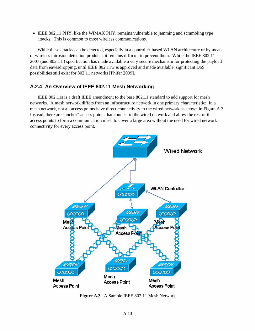
A.13
IEEE 802.11 PHY, like the WiMAX PHY, remains vulnerable to jamming and scrambling type attacks. This is common to most wireless communications.
While these attacks can be detected, especially in a controller-based WLAN architecture or by means of wireless intrusion detection products, it remains difficult to prevent them. While the IEEE 802.11-2007 (and 802.11i) specification has made available a very secure mechanism for protecting the payload data from eavesdropping, until IEEE 802.11w is approved and made available, significant DoS possibilities still exist for 802.11 networks [Phifer 2009].
A.2.4 An Overview of IEEE 802.11 Mesh Networking
IEEE 802.11s is a draft IEEE amendment to the base 802.11 standard to add support for mesh networks. A mesh network differs from an infrastructure network in one primary characteristic: In a mesh network, not all access points have direct connectivity to the wired network as shown in Figure A.3. Instead, there are “anchor” access points that connect to the wired network and allow the rest of the access points to form a communication mesh to cover a large area without the need for wired network connectivity for every access point.
Figure A.3. A Sample IEEE 802.11 Mesh Network
A.14
The mesh APs need the ability to route frames received from their clients to the wired network. This is usually accomplished by running a routing algorithm such as Ad-hoc On-Demand Distance Vector (AODV) [Mobility Management and Networking Laboratory 2009]. An IEEE 802.11-based mesh network inherits the properties of the base network and adds the following operational concerns:
Stability of the network routing algorithm in the event of multiple failures
Firmware management for access points and how to recover when an upgrade fails
Latency and Jitter through the mesh
Frame goodput and throughput in a multi-hop network where typically frames that have traveled many mesh hops have a lower chance of getting through without a prioritization mechanism
Congestion in the uplink ports of the mesh access points that are close to the anchor access points because they are the primary access to the wired network.
A.2.5 An Overview of IEEE 802.11 Controller-Based Wireless Networks
In the Control and Provisioning of Wireless Access Points Protocol Specification, IETF standardized a controller-based WLAN architecture [Internet Engineering Task Force 2009]. A WLAN controller serves as a coordinating and managing entity for many access points. This architecture allows network administrators to centrally manage their WLAN. It also allows them to gather information from all of their access points and correlate and coordinate this information to improve both network security and radio resource management. Finally, the controller architecture allows for better radio coverage and improved roaming response. Most vendors that offer enterprise class wireless products offer a controller-based solution. For the electric power system, a controller-based WLAN architecture is recommended due to the radio resource planning and security monitoring capabilities that are enhanced with the addition of a WLAN controller.
A.3 IEEE 802.15.4 Wireless Sensor Networks
The IEEE 802.15.4 protocol specifies the physical (radio transceiver) and the medium access control layers for wireless sensor networks (WSNs). The primary goal of IEEE 802.15.4 is to provide reliable, power-efficient communication capabilities for low data rate wireless networks. The driver for the development of the 802.15.4 standard is the ZigBee protocol, although there are competing protocols such as WirelessHART and ISA100.11a that also use the 802.15.4 PHY but define their own MAC and network layers [Petersen et al. 2008b]. The latest revision to the 802.15.4 specification is referred to as IEEE 802.15.4-2006. There are established vendors such as Emerson and Honeywell that are offering wireless sensor products based on the IEEE 802.15.4 technology. WSNs are being investigated for use by oil and gas industries [Petersen et al. 2008a; Petersen et al. 2008b].
A WSN offers advantages compared to traditional serial-line-wired sensors. First and foremost is the deployment flexibility where new sensors can be deployed, for example to modernize a process control system, with minimal advanced preparation because no power or wires are necessary. Second, compared to a serial line that transmits data at 9600 bits/sec, a wireless sensor can reach speeds up to 250,000 bits/sec when sending data. Therefore, a wireless sensor can transmit more samples per second (albeit reducing battery life as a byproduct). Finally, unlike cabling that tends to get confusing when hundreds of
A.15
sensors are being used, a wireless network remains the same. With enhanced location capability, even the location of a wireless sensor may be pinned with 3-6 ft accuracy using radio frequency triangulation.
Two types of devices are in an 802.15.4 based WSN. A Full-Function Device (FFD) is capable of serving as the coordinator for the WSN and has the ability to route packets between different nodes in the wireless network as well as acting as a gateway between the wired and the wireless networks. A Reduced-Function Device is a device that has a limited implementation of the protocol and can only act as a leaf node in the network. An Reduced-Function Device is usually a simple sensor that only needs to send minimal amount of information such as a presence detector. An 802.15.4 WSN must include at least one FFD acting as a WSN-wide coordinator. The coordinator provides synchronization services to the network and manages other devices on the WSN.
A WSN based on IEEE 802.15.4 supports three main topologies:
1. Star Topology: In the star topology, a unique FFD acts as the coordinator. Each device that is part of the WSN must send its data to the coordinator, which will then route the data appropriately. Due to the additional traffic that is handled by the coordinator, the coordinator is allowed to be powered by the electric system. Because of the centralization of traffic to a single point, the star topology is suitable for applications such as home automation or communication between a smart meter and smart appliances in the home.
2. Peer-to-Peer Topology: The peer-to-peer topology also incorporates a coordinator that handles synchronization, but unlike the star topology, all devices in the network can communicate with each other directly. Similar to IEEE 802.11 mesh networks, the 802.15.4 mesh topology requires routing of packets to enable any-to-any communication within the network. The 802.15.4 standard assumes that the routing functionality is handled by the network layer.
3. Cluster-Tree Topology: The cluster-tree topology allows the WSN to scale by dividing up the network into clusters of peer-to-peer networks. For each peer-to-peer network, a small number of FFDs act as gateways to provide connectivity to other peer-to-peer networks. The complete cluster is managed by a coordinator FFD, whereas each cluster is managed by its cluster head. While the cluster-tree topology is defined by the 802.15.4 standard, the formation, management, and network routing algorithms of clusters are expected to be defined by the network layer.
In the following sections, we discuss the 802.15.4 PHY that forms the basis of ZigBee, Wireless HART, and ISA 100.11a protocols. We will then review the 802.15.4 MAC layer and briefly discuss the Time Synchronized Mesh Protocol (TSMP), ISA 100.11a, and ZigBee network layers. We finish by presenting a discussion of the security properties of 802.15.4 WSNs.
A.3.1 IEEE 802.15.4 Physical (PHY) Layer
The 802.15.4 PHY layer performs clock synchronization, modulation, demodulation, and handles data transmission to and reception from the wireless medium. Three frequency bands are defined for IEEE 802.15.4 PHY: One channel between 868 and 868.6 MHz, ten channels between 902 and 928 MHz, and sixteen channels between 2.4 and 2.4835 GHz. All of these channels operate in unlicensed spectrum.
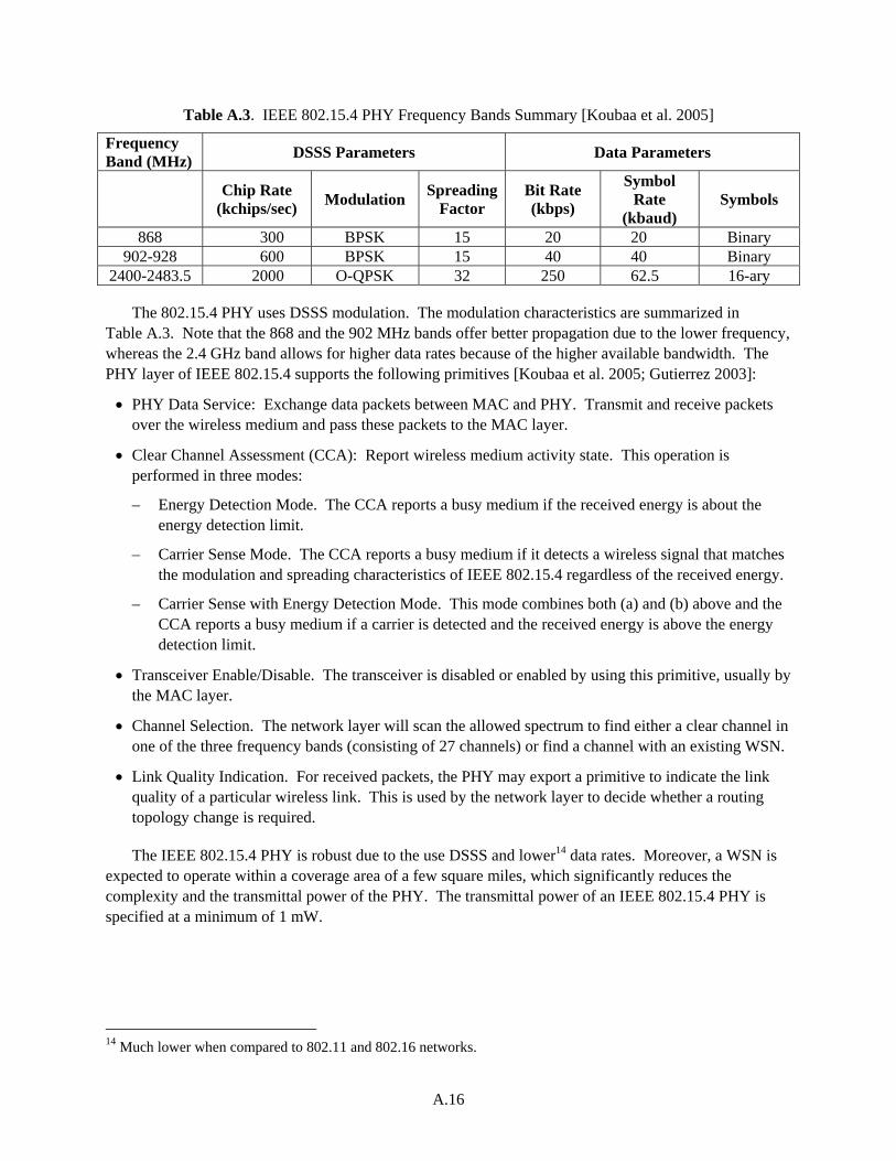
A.16
Table A.3. IEEE 802.15.4 PHY Frequency Bands Summary [Koubaa et al. 2005]
Frequency Band (MHz)
DSSS Parameters Data Parameters
Chip Rate
(kchips/sec) Modulation
Spreading Factor
Bit Rate (kbps)
Symbol Rate
(kbaud) Symbols
868 300 BPSK 15 20 20 Binary 902-928 600 BPSK 15 40 40 Binary
2400-2483.5 2000 O-QPSK 32 250 62.5 16-ary
The 802.15.4 PHY uses DSSS modulation. The modulation characteristics are summarized in Table A.3. Note that the 868 and the 902 MHz bands offer better propagation due to the lower frequency, whereas the 2.4 GHz band allows for higher data rates because of the higher available bandwidth. The PHY layer of IEEE 802.15.4 supports the following primitives [Koubaa et al. 2005; Gutierrez 2003]:
PHY Data Service: Exchange data packets between MAC and PHY. Transmit and receive packets over the wireless medium and pass these packets to the MAC layer.
Clear Channel Assessment (CCA): Report wireless medium activity state. This operation is performed in three modes:
– Energy Detection Mode. The CCA reports a busy medium if the received energy is about the energy detection limit.
– Carrier Sense Mode. The CCA reports a busy medium if it detects a wireless signal that matches the modulation and spreading characteristics of IEEE 802.15.4 regardless of the received energy.
– Carrier Sense with Energy Detection Mode. This mode combines both (a) and (b) above and the CCA reports a busy medium if a carrier is detected and the received energy is above the energy detection limit.
Transceiver Enable/Disable. The transceiver is disabled or enabled by using this primitive, usually by the MAC layer.
Channel Selection. The network layer will scan the allowed spectrum to find either a clear channel in one of the three frequency bands (consisting of 27 channels) or find a channel with an existing WSN.
Link Quality Indication. For received packets, the PHY may export a primitive to indicate the link quality of a particular wireless link. This is used by the network layer to decide whether a routing topology change is required.
The IEEE 802.15.4 PHY is robust due to the use DSSS and lower14 data rates. Moreover, a WSN is expected to operate within a coverage area of a few square miles, which significantly reduces the complexity and the transmittal power of the PHY. The transmittal power of an IEEE 802.15.4 PHY is specified at a minimum of 1 mW.
14 Much lower when compared to 802.11 and 802.16 networks.
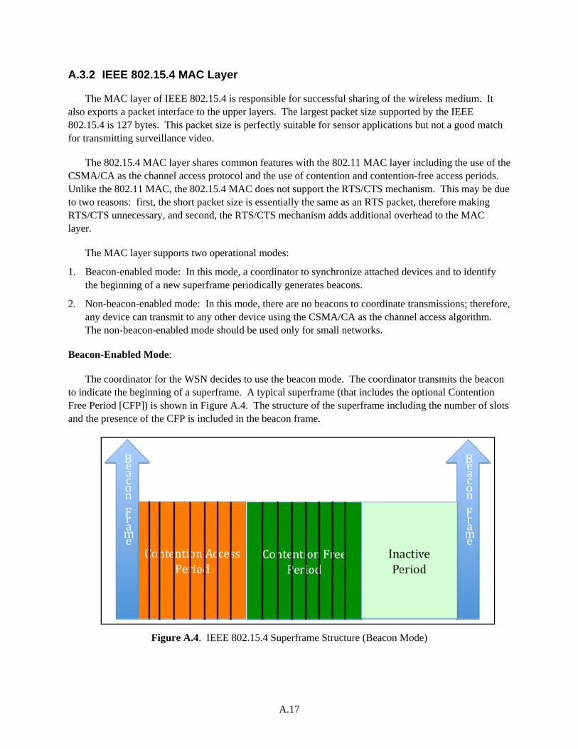
A.17
A.3.2 IEEE 802.15.4 MAC Layer
The MAC layer of IEEE 802.15.4 is responsible for successful sharing of the wireless medium. It also exports a packet interface to the upper layers. The largest packet size supported by the IEEE 802.15.4 is 127 bytes. This packet size is perfectly suitable for sensor applications but not a good match for transmitting surveillance video.
The 802.15.4 MAC layer shares common features with the 802.11 MAC layer including the use of the CSMA/CA as the channel access protocol and the use of contention and contention-free access periods. Unlike the 802.11 MAC, the 802.15.4 MAC does not support the RTS/CTS mechanism. This may be due to two reasons: first, the short packet size is essentially the same as an RTS packet, therefore making RTS/CTS unnecessary, and second, the RTS/CTS mechanism adds additional overhead to the MAC layer.
The MAC layer supports two operational modes:
1. Beacon-enabled mode: In this mode, a coordinator to synchronize attached devices and to identify the beginning of a new superframe periodically generates beacons.
2. Non-beacon-enabled mode: In this mode, there are no beacons to coordinate transmissions; therefore, any device can transmit to any other device using the CSMA/CA as the channel access algorithm. The non-beacon-enabled mode should be used only for small networks.
Beacon-Enabled Mode:
The coordinator for the WSN decides to use the beacon mode. The coordinator transmits the beacon to indicate the beginning of a superframe. A typical superframe (that includes the optional Contention Free Period [CFP]) is shown in Figure A.4. The structure of the superframe including the number of slots and the presence of the CFP is included in the beacon frame.
Figure A.4. IEEE 802.15.4 Superframe Structure (Beacon Mode)
A.18
If no CFP is present, a device wishing to transmit data must compete with other devices using the slotted CSMA/CA mechanism. All transmissions must be finished by the beginning of the inactive period.
If a CFP is included in the superframe, then QoS guarantees can be made to devices that need it. The CFP consists of Guaranteed Time Slots (GTSs) that are pre-allocated by the WSN coordinator to sensors that require low latency or guaranteed bandwidth. The CFP starts at a slot boundary following the contention access period (CAP). The coordinator can allocate up to seven GTSs, and each GTS may occupy more than a single time slot. When a CFP is present, all CAP traffic must be finished before the start of the CFP. Note that a GTS may only be used between a coordinator and a device. It is not for use for peer-to-peer communication.
The inactive period is for devices to go into sleep mode so that they can conserve power.
Non-Beacon-Enabled Mode:
When the coordinator chooses the non-beacon mode, there is no coordination and no superframes. The devices in the WSN must use an unslotted CSMA/CA mechanism to access the channel. All messages that are transmitted must be sent according to CSMA/CA. Acknowledgment messages and an immediate data response to a query are excluded from this requirement. Unfortunately, CSMA/CA suffers from low channel access efficiency and this mode does not scale to a high number of devices in the WSN.
In summary, the 802.15.4 MAC layer offers both guaranteed and contention-based access for devices in the WSN; provides a variety of power-saving modes including the inactive period and the polling mode where the coordinator can buffer traffic for the device; and supports both peer-to-peer and star topologies.
Security Functions Provided by the 802.15.4 MAC Layer
The 802.15.4 MAC layer provides security services to the application layers that request it. Note that ZigBee protocol, which is the main driver of IEEE 802.15.4 development, uses its own network layer security mechanisms for multi-hop transmissions. The TSMP and ISA100.11a protocol use the 802.15.4 PHY layer and radios, but they implement completely different MAC and network layers. In our opinion, the main reason for this is the security issues associated with the initial version of IEEE 802.15.4 published in 2003. These security issues are outlined in Section A.3.6. The 2006 revision of the standard fixes most of these security flaws. IEEE is currently working on another revision of the standard to further enhance the MAC layer [Struick 2008].
Performance of the IEEE 802.15.4 MAC
In [Zheng and Lee 2006], a detailed analysis of the performance of 802.15.4 MAC is presented. In this document, we will highlight some of the results from [Zheng and Lee 2006]. When 802.15.4 is compared to 802.11, as the offered packet load is increased from 0.1 packets/sec to 10 packets/second, the successful packet delivery rate for 802.11 varies from 99.53% to 98.65%. For 802.15.4 MAC under the same scenario, the packet delivery rate drops from 95.4% to 55.26%. The main reason for this nearly 50% drop in performance is the lack of an RTS/CTS mechanism in 802.15.4. The RTS/CTS mechanism improves throughput under high load and stabilizes the network.
A.19
Zheng and Lee [2006] also discovered that the suggested back-off length in 802.15.4 is too short, especially for long frames. This means that in heavily loaded 802.15.4 networks, there is a chance that no traffic will get through once the wireless medium starts experiencing collisions.
In our opinion, the performance of the 802.15.4 MAC is suitable for small networks. This fits well within the original mission of ZigBee in home automation but may not be suitable for large-scale wireless sensor networks. This is why WirelessHART and ISA100.11a have adopted different MAC protocols to achieve large-scale deployment capabilities.
A.3.3 TSMP (WirelessHART) MAC and Network Layer
TSMP was developed by Dust Networks as part of their sensor radio product line. It also forms the basis of the WirelessHART protocol that is an addition to the HART protocol commonly used in oil and gas industries. At least the 2.4 GHz version of TSMP uses the IEEE 802.15.4 PHY; therefore, we include a summary of TSMP in this document. For detailed information on TSMP, we refer the reader to [Doherty and Teasdale 2006; Dust Networks 2009].
TSMP implements the media access control and the network layers. It handles routing of the packets in the mesh network, which, as we saw previously, was out of scope for the base IEEE 802.15.4 specification. TSMP employs a packet-based protocol where a transmission contains a single packet and acknowledgements (ACKs) are generated when a packet is received and its integrity is verified. TSMP uses 40 bytes out of the 127-byte 802.15.4 packet for its own header. The TSMP header consists of MAC, Network headers, Payload, message integrity codes, and a Frame Check Sequence.
TSMP consists of five components:
1. Time synchronized communication:15 TSMP uses time division multiple access (TDMA) in place of the CSMA/CA. This technique introduces time synchronization overhead but allows for collision-free communication that can support bandwidth guarantees and low latencies. To maintain time synchronization, TSMP does not use beacons. Instead, a network-wide time synchronization protocol piggybacked on ACK packets allows WSN nodes to maintain a common time base. A second benefit of maintaining a common time base is the ability to use frequency hopping.
2. Frequency Hopping:16 In addition to using TDMA for multiple access, TSMP also employs frequency hopping to increase the robustness of communication in the presence of an interferer and also the effective bandwidth of the channel. Using frequency hopping when combined with the DSSS modulation of the 802.15.4 radios increases the resistance of the WSN to common interferers such as 802.11 and Bluetooth. In the 2.4 GHz band, TSMP hops between all 16 channels. This has the effect of increasing overall WSN data transmission capacity 16-fold.
3. Automatic node joining and network formation: TSMP Network layer protocols support self-organizing and automatic route discovery. Each TSMP node is capable of discovering neighbors, measuring received signal strength, and acquiring synchronization and frequency hopping
15 Time synchronized communication is an enhancement on the base IEEE 802.15.4 MAC layer. 16 Frequency hopping is commonly used to increase the robustness of a radio network against a narrow-band interferer. Direct-sequence spread spectrum is effective against a wide-band interferer. By combining these two technologies, TSMP has improved the base 802.15.4 specification.
A.20
information. It will then use this information to establish mesh network routing paths. TSMP messages are encrypted and include a network identifier. A TSMP node will only join a network that matches its own provisioned network identifier. Each node in the TSMP network is also configured with a join key. If a node has an incorrect key, it will not be able to join the WSN.
4. Redundant mesh routing: TSMP builds a mesh network to transmit packets to its recipients. One of the properties of a wireless mesh network is its ability to provide spatial diversity. Spatial diversity enables the network to bypass nodes that may be disabled or being interfered with by an adversary. The number of network paths in a large network may be controlled by limiting the number of adjacencies that a node has.
5. Secure message transfer: TSMP uses AES-CTR mode for encryption with a key length of 128 bits. A timestamp is used to prevent replay attacks. TSMP uses two 32-bit MICs. One of these protects network layer headers and payload. The second MIC protects the MAC layer information.
A.3.4 ISA 100.11a MAC and Network Layer
ISA100.11a standard was approved on September 9, 2009 by the International Society of Automation. ISA100.11a defines a wireless industrial sensor network protocol stack and, like TSMP, uses the 802.15.4 PHY but replaces the 802.15.4 MAC almost completely. One of the benefits of the ISA100.11a is the built-in compatibility with the IETF’s 6LoWPAN efforts.17 The network layer of the standard is fully compatible with IPv6 and also supports the 16 bit compressed address format to shorten the headers that are sent over the RF medium.
The ISA100.11a standard places the following additional requirements on the radio physical (PHY) layer compared to the base 802.15.4 PHY:
1. The PHY must be able to change channels in less than 200 micro-seconds.
2. Because the CSMA/CA mode is optional in ISA100.11a, the PHY must export a control primitive to be able to turn off the carrier sense mechanism.
3. IEEE802.15.4 channels 11-25 must be supported. Support for channel 26 is optional. ISA100.11a only operates in the 2.400-2.4835 GHz band.
4. Over-the-air data rate is 250 Kbps.
The MAC for ISA100.11a is defined in the Data Link Layer (DL) section in clause 9. In summary, the ISA100.11a DL shares only the basic MAC frame with the 802.15.4 MAC. It is a complete rewrite of the MAC layer that supports a synchronized time base and TDMA for channel access with assigned bandwidth by use of “contracts.” Because the standard supports fully meshed wireless networking, the DL also includes mesh routing capabilities. To improve robustness of the wireless network, the network uses three types of diversity:
Space diversity by use of the mesh network to utilize multiple paths to transmit information.
Frequency diversity by using either per-timeslot hopping or slow frequency hopping (every 100 - 400 ms).
17 6LoWPAN specifications can be accessed at http://www.ietf.org/dyn/wg/charter/6lowpan-charter.html.
A.21
Time diversity by incorporating a retry mechanism.
When combined with the excellent performance of the DSSS PHY layer, these diversities provide robust networking capabilities. In fact, because the ISA100.11a DL is very similar to the WirelessHART MAC, we expect the robustness to be similar where empirical evidence suggests 99.9% or better reliability.
ISA100.11a security is robust, mandating integrity checks using a MIC and optional encryption at the DL. Because ISA100.11a also defines a transport layer (TL), security at the transport layer is supported as well. The DL and TL keys are both 128 bits. AES-CCM is the preferred security algorithm. The maximum life of a key in the network is 48.5 days and the keys must be refreshed before they expire. For a device to join an ISA100.11a network, it needs to possess one of a shared global key, a private symmetric key, or a certificate. The device is provisioned with the join information before being deployed. Our preferred method for joining a network is the use of a certificate that enables cryptographically strong mutual authentication. ISA100.11a specifically disallows the use of security modes that don’t provide integrity checks, including the problematic encryption-only mode of IEEE802.15.4.
The authors have one security concern about the ISA100.11a. The “random” nonce that is fed into the AES-CCM algorithm in ISA100.11a is not random. In fact, when an adversary has access to the time base (or a GPS) and can timestamp packets as they are received, there is a good chance of guessing the nonce value. For the DL, only 255 guesses are required, assuming that the time base is available. For the TL, the availability of the time base makes it possible to know the nonce value. Once the nonce value is known (or guessed), a time-memory-trade-off attack can be performed on AES [Hong and Sarkar 2005]. The effective key strength is reduced from 128 to 85 bits.
In summary, ISA100.11a is a significant improvement over the 802.15.4 specification and has properties comparable to WirelessHART/TSMP.
A.3.5 ZigBee Network Layer
ZigBee technology was one of the main drivers of the development of IEEE 802.15.4 protocol stack. ZigBee uses the 802.15.4 PHY and MAC layers and implements a network layer protocol. ZigBee network layer is responsible for [Kinney 2003]:
Starting a network. Able to become a ZigBee coordinator and establish a new network.
Joining and leaving a network.
Configuring a new device such that it can join a ZigBee network.
Addressing. Assign and maintain network layer addresses.
Synchronization. Achieve synchronization with other ZigBee devices in the network either through tracking beacons or by polling.
Security for outgoing and incoming frames. ZigBee does not rely on the IEEE 802.15.4 MAC layer security mechanisms. Instead, ZigBee relies on the network layer in order to provide confidentiality and integrity. AES CCM mode is used to provide both confidentiality and integrity with a key size of 128 bits.
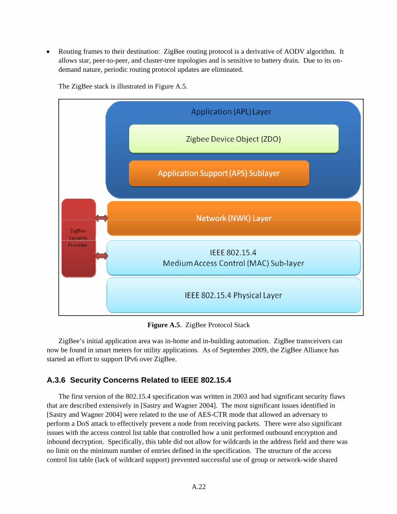
A.22
Routing frames to their destination: ZigBee routing protocol is a derivative of AODV algorithm. It allows star, peer-to-peer, and cluster-tree topologies and is sensitive to battery drain. Due to its on-demand nature, periodic routing protocol updates are eliminated.
The ZigBee stack is illustrated in Figure A.5.
Figure A.5. ZigBee Protocol Stack
ZigBee’s initial application area was in-home and in-building automation. ZigBee transceivers can now be found in smart meters for utility applications. As of September 2009, the ZigBee Alliance has started an effort to support IPv6 over ZigBee.
A.3.6 Security Concerns Related to IEEE 802.15.4
The first version of the 802.15.4 specification was written in 2003 and had significant security flaws that are described extensively in [Sastry and Wagner 2004]. The most significant issues identified in [Sastry and Wagner 2004] were related to the use of AES-CTR mode that allowed an adversary to perform a DoS attack to effectively prevent a node from receiving packets. There were also significant issues with the access control list table that controlled how a unit performed outbound encryption and inbound decryption. Specifically, this table did not allow for wildcards in the address field and there was no limit on the minimum number of entries defined in the specification. The structure of the access control list table (lack of wildcard support) prevented successful use of group or network-wide shared
A.23
keying. The lack of a lower limit for the minimum number of entries in the access control list table prevented use of pairwise keys as well. These flaws when combined made the MAC layer security mechanisms in IEEE 802.15.4-2003 ineffective [Sastry and Wagner 2004].
The 802.15.4-2006 specification was able to alleviate most of these flaws by redefining the security mechanisms in the MAC layer. The improvements that were made in 2006 to 802.15.4 can be summarized as [Struik 2008]:
Confidentiality, data authenticity, and replay protection as part of the security suite.
Protection of broadcast and multicast frames possible.
Easier setup of protection parameters possible.
Possibility of varying protection per frame using a single key.
Optimization of storage of keying material by introducing the key and device tables.
Security policy checks per frame possible.
Key usage policy checks possible to precisely bind a key to a frame. This prevents use of older keys after a rekey operation has happened.
These enhancements fix most of the concerns outlined in [Sastry and Wagner 2004]. Unfortunately, the ACK frames are still unsecured, which leaves the protocol open to a DoS attack that causes undetected packet loss by directed jamming and then forging ACK packets. Turning off MAC layer acknowledgments and employing application-level acknowledgments can overcome this attack. While the protocol still allows an encryption-only mode without a MIC, setting the minimum security layer higher than the encryption-only level (indicated by level 4) will prevent attacks associated with encryption-only mode. However, unfortunately, setting the security level to a higher level disallows the use of authentication-only security suites because the level is implemented as a greater-than check in the MAC.
ZigBee protocol uses network layer security. TSMP/WirelessHART and ISA 100.11a define an alternate MAC with its own security protocols.
A.4 2G/3G/4G Cellular Networks
The cellular communication networks have been available in the United States since the Advanced Mobile Phone Service (AMPS) was submitted for approval to the Federal Communications Commission in 1972. The Federal Communications Commission approved the proposal in 1982 and allocated frequencies in the 824-894 MHz band. AMPS was introduced by AT&T in 1983. AMPS is based on an analog technology that used frequency division multiple access (FDMA). The successor to AMPS, D-AMPS, was introduced in 1990 but did not get wide-scale deployment until the mid-1990s. AMPS was a widely available system supported in North America and other parts of the world. Unlike in North America, there were multiple competing systems in Europe that were not interoperable. These analog systems are commonly referred to as first-generation (1G) technologies that were firmly focused on voice communications. The 2G networks followed the 1G networks in the 1990s. In Europe, a continent-wide (and now worldwide) digital cellular phone standard was developed. This standard is referred to as “Groupe Special Mobile” or “Global System for Mobile Communications” and is usually abbreviated as
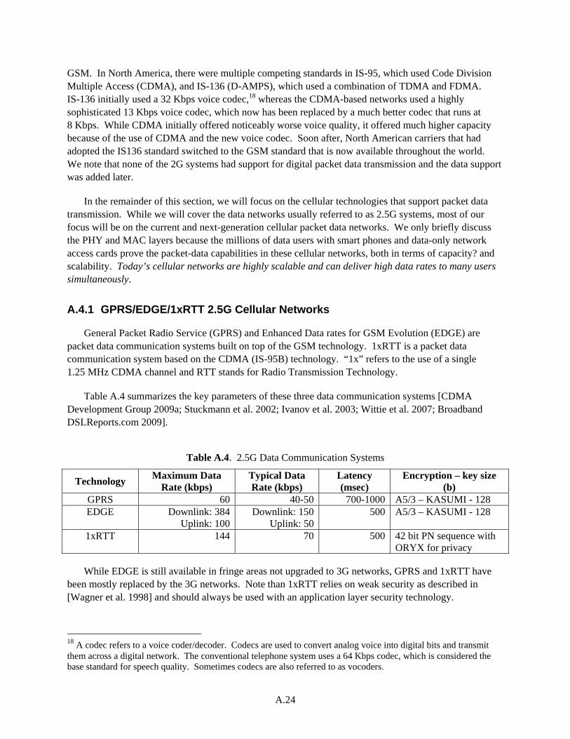
A.24
GSM. In North America, there were multiple competing standards in IS-95, which used Code Division Multiple Access (CDMA), and IS-136 (D-AMPS), which used a combination of TDMA and FDMA. IS-136 initially used a 32 Kbps voice codec,18 whereas the CDMA-based networks used a highly sophisticated 13 Kbps voice codec, which now has been replaced by a much better codec that runs at 8 Kbps. While CDMA initially offered noticeably worse voice quality, it offered much higher capacity because of the use of CDMA and the new voice codec. Soon after, North American carriers that had adopted the IS136 standard switched to the GSM standard that is now available throughout the world. We note that none of the 2G systems had support for digital packet data transmission and the data support was added later.
In the remainder of this section, we will focus on the cellular technologies that support packet data transmission. While we will cover the data networks usually referred to as 2.5G systems, most of our focus will be on the current and next-generation cellular packet data networks. We only briefly discuss the PHY and MAC layers because the millions of data users with smart phones and data-only network access cards prove the packet-data capabilities in these cellular networks, both in terms of capacity? and scalability. Today’s cellular networks are highly scalable and can deliver high data rates to many users simultaneously.
A.4.1 GPRS/EDGE/1xRTT 2.5G Cellular Networks
General Packet Radio Service (GPRS) and Enhanced Data rates for GSM Evolution (EDGE) are packet data communication systems built on top of the GSM technology. 1xRTT is a packet data communication system based on the CDMA (IS-95B) technology. “1x” refers to the use of a single 1.25 MHz CDMA channel and RTT stands for Radio Transmission Technology.
Table A.4 summarizes the key parameters of these three data communication systems [CDMA Development Group 2009a; Stuckmann et al. 2002; Ivanov et al. 2003; Wittie et al. 2007; Broadband DSLReports.com 2009].
Table A.4. 2.5G Data Communication Systems
Technology Maximum Data
Rate (kbps) Typical Data Rate (kbps)
Latency (msec)
Encryption – key size (b)
GPRS 60 40-50 700-1000 A5/3 – KASUMI - 128 EDGE Downlink: 384
Uplink: 100Downlink: 150
Uplink: 50500 A5/3 – KASUMI - 128
1xRTT 144 70 500 42 bit PN sequence with ORYX for privacy
While EDGE is still available in fringe areas not upgraded to 3G networks, GPRS and 1xRTT have been mostly replaced by the 3G networks. Note than 1xRTT relies on weak security as described in [Wagner et al. 1998] and should always be used with an application layer security technology.
18 A codec refers to a voice coder/decoder. Codecs are used to convert analog voice into digital bits and transmit them across a digital network. The conventional telephone system uses a 64 Kbps codec, which is considered the base standard for speech quality. Sometimes codecs are also referred to as vocoders.
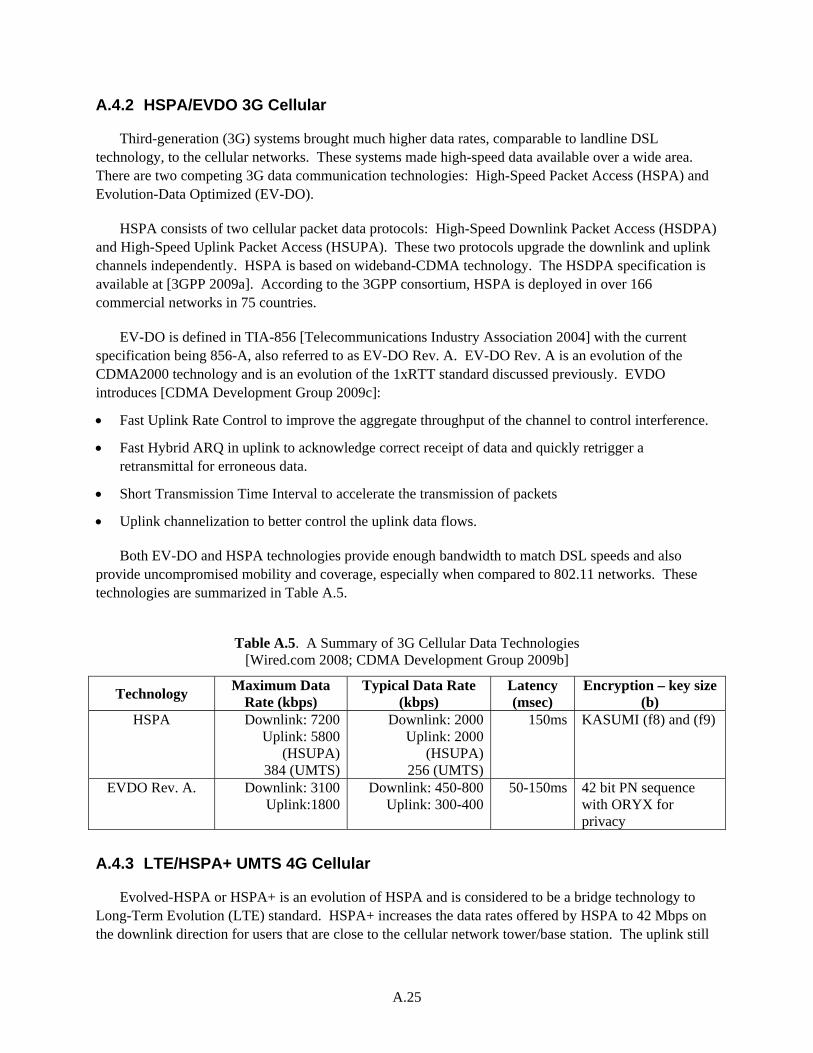
A.25
A.4.2 HSPA/EVDO 3G Cellular
Third-generation (3G) systems brought much higher data rates, comparable to landline DSL technology, to the cellular networks. These systems made high-speed data available over a wide area. There are two competing 3G data communication technologies: High-Speed Packet Access (HSPA) and Evolution-Data Optimized (EV-DO).
HSPA consists of two cellular packet data protocols: High-Speed Downlink Packet Access (HSDPA) and High-Speed Uplink Packet Access (HSUPA). These two protocols upgrade the downlink and uplink channels independently. HSPA is based on wideband-CDMA technology. The HSDPA specification is available at [3GPP 2009a]. According to the 3GPP consortium, HSPA is deployed in over 166 commercial networks in 75 countries.
EV-DO is defined in TIA-856 [Telecommunications Industry Association 2004] with the current specification being 856-A, also referred to as EV-DO Rev. A. EV-DO Rev. A is an evolution of the CDMA2000 technology and is an evolution of the 1xRTT standard discussed previously. EVDO introduces [CDMA Development Group 2009c]:
Fast Uplink Rate Control to improve the aggregate throughput of the channel to control interference.
Fast Hybrid ARQ in uplink to acknowledge correct receipt of data and quickly retrigger a retransmittal for erroneous data.
Short Transmission Time Interval to accelerate the transmission of packets
Uplink channelization to better control the uplink data flows.
Both EV-DO and HSPA technologies provide enough bandwidth to match DSL speeds and also provide uncompromised mobility and coverage, especially when compared to 802.11 networks. These technologies are summarized in Table A.5.
Table A.5. A Summary of 3G Cellular Data Technologies [Wired.com 2008; CDMA Development Group 2009b]
Technology Maximum Data
Rate (kbps) Typical Data Rate
(kbps) Latency (msec)
Encryption – key size (b)
HSPA Downlink: 7200 Uplink: 5800
(HSUPA) 384 (UMTS)
Downlink: 2000 Uplink: 2000
(HSUPA) 256 (UMTS)
150ms KASUMI (f8) and (f9)
EVDO Rev. A. Downlink: 3100 Uplink:1800
Downlink: 450-800 Uplink: 300-400
50-150ms 42 bit PN sequence with ORYX for privacy
A.4.3 LTE/HSPA+ UMTS 4G Cellular
Evolved-HSPA or HSPA+ is an evolution of HSPA and is considered to be a bridge technology to Long-Term Evolution (LTE) standard. HSPA+ increases the data rates offered by HSPA to 42 Mbps on the downlink direction for users that are close to the cellular network tower/base station. The uplink still
A.26
uses the HSUPA and is limited to 5.8 Mbps. The latencies are improved over HSPA. In the United States, only one wireless carrier has committed to deploying HSPA+ technology, whereas the other carriers have committed to deploying LTE technology.
LTE is a fourth-generation cellular technology primarily designed to address the growing use of data in cellular networks. LTE is an all-Internet Protocol (all-IP) technology that simplifies the interface between the cellular network and the internet. In the United States, the National Public Safety Telecommunications Council has also endorsed LTE as the desired broadband technology in the 700 MHz public safety band [National Public Safety Telecommunications Council 2009]. LTE is standardized in 3GPP Release 9 (http://www.3gpp.org) and is currently in carrier trials in the U.S. All major U.S. wireless carriers have committed to deploying LTE with two carriers scheduled to deploy by 2010. The following are design goals for LTE:
Increased peak data rates: 100 Mbps downlink and 50 Mbps in the uplink using a 20 MHz spectrum
Reduction of radio access network latency to 10 ms
Improved spectrum efficiency (two to four times of HSPA)
IP-optimized
Support for both frequency and time division duplexed systems
Support for interworking with 3G systems
Improved support for broadcasting
Improved coverage and data rates at cell edge
Reduced operational complexity
LTE physical layer uses OFDM on the downlink and a version of OFDM referred to as SC-FDMA on the uplink. OFDM is also used in 802.11 and WiMAX. In current trials, LTE speeds of 140 Mbps have been demonstrated [Ericsson 2007]. The theoretical maximum data rates for LTE downlink are 326.4 Mbps for 4 x 4 MIMO antennas and 172.8 Mbps for 2 x 2 antennas in a 20 MHz band. For the uplink direction, the theoretical maximum bandwidth is capped at 86.4 Mbps.
LTE uses Diameter as its authentication and authorization protocol. Diameter is defined in RFC3588 by IETF. The LTE Security Architecture is specified in 3GPP TS 33.401 rev. 9.1.0. One of the security improvements in LTE is the protection of user traffic either via AES (128 bit keys) or SNOW3G (128 bit keys) algorithms.
LTE is accompanied by the LTE System Architecture Evolution (LTE-SAE) that defines an all IP-based back-end network to handle the traffic generated by mobile users. LTE-SAE reduces the number of nodes that are involved in the communications path before the data is handed to the global internet to two: the base station and the SAE gateway.
In summary, LTE provides WLAN-type bandwidth in a much wider area, and due to its all-IP network architecture, LTE is a significant improvement over the 3G systems.

A.27
A.4.4 Interconnecting a Private Network to a Public Cellular Network
The public cellular networks available today in North America and the rest of the world provide significant bandwidth and improved latencies for data traffic. LTE, which should be available in 2010, provides data rates comparable to wired services such as cable modem and DSL and can also match them for latency as well. The cellular networks also benefit from economies of scale where the cost of developing communications hardware and software is shared among billions of users. It is estimated that there will be 3.4 billion broadband users across the world in 2010? and about 80% of them will be mobile broadband subscribers. This is a big benefit in containing the costs of smart grid equipment, such as smart meters, while having reliable communication capability.
For all practical purposes, the networks that interconnect the electric power system will need to be private networks. The cellular network is a public network. How will these two networks interconnect? This is not as complicated a topic as it sounds. The public carriers have long-term experience with supporting virtual private networks over a public backbone network. These networks are implemented either via IPSec or Multi-Protocol Label Switching. For example, it is feasible to tag readings coming from the smart meters in the smart grid via a cellular network and directly link this data to a private network belonging to an electric utility. These meter-reading packets would be logically isolated from the traffic coming from the rest of the users of the network and would never be transferred over the public network. In order to guarantee security, we recommend that any communication that traverses a public network to be secured either at the network layer by using IPSec (RFC2401) or by using SSL/TLS (RFC5246) using strong encryption and authentication. The users must not rely solely on the security provided by the DL, which in this case is the public cellular network.
A.5 Legacy Wireless Communications in the Electric Power System
Numerous other types of wireless technologies are used in the electric power system: Licensed digital microwave, two-way radios, paging systems, analog microwave, and 900 MHz multiple address system radios, among others. We will discuss these technologies briefly because they are well understood by the utility industry and tend to use proprietary protocols.
One of the wireless technologies used in the electric power system is the wireless supervisory control and data acquisition (SCADA) technology.19 Many of the wireless SCADA systems operate in a “broadcast mode” where all devices on a particular channel can communicate with each other. Any message sent out on this channel can be received by all others on the channel—in some respects, similar to several computers on the same hub on an IT network.
Members of the SCADA system community have tended to shy away from using popular IT security solutions on control systems, as IT solutions tend to be more tedious to configure and more difficult to maintain. For example, solutions like VPN connections often are not possible on the low-bandwidth connections in SCADA systems. As security concerns rise for critical infrastructure protection, vendors are attempting to fill the need for secure communications.
19 The following text is adapted from a Pacific Northwest National Laboratory internal technical report titled “Vulnerabilities in Proprietary SCADA Communication Equipment” by Ben Davis written in June 2007.
A.28
Wireless communication provides many advantages but comes with many security concerns. Many vendors are beginning to manufacture and sell wireless systems designed to communicate using proprietary protocols. Several of these proprietary protocols employ encryption between the wireless devices to provide security for the data in transmission. However, these vendors attempt to provide equipment that functions similarly to traditional SCADA equipment, including the capability to function in “broadcast” mode where devices on the same channel may communicate freely.
The problem with this approach is that this “secure” equipment provides a false sense of security. It is not secure enough to protect against a cyber attack. Even more concerning is the fact that attackers do not need to reverse engineer the proprietary equipment or software, nor is a deep understanding of cryptology required to attack these networks.
The security measures in these devices are designed to be transparent to the rest of the system—making it compatible with the maximum amount of other equipment and simple to configure. When data is received by Radio A, Radio A encrypts the data and sends it out to the communication channel. Radio B receives the data, decrypts it, and sends it out to its connected device. The encryption is transparent to the user and to the devices on both ends of the radios, so all the attacker needs to do is become a “user" by obtaining a compatible device—a Radio C from the same vendor, for example. An attacker can learn what equipment is used by an organization from corporate paperwork and websites, social engineering, job postings, or even by simply observing the equipment located in the field. With the right equipment, the attacker can simply become part of the same channel and will be able to obtain the data sent out to the channel, as well as inject malicious traffic.
Many vendors respond to these threats by stating that it is not feasible for an attacker to access these channels because they would have to guess the exact configuration of the implemented devices to join the broadcast channel. This is simply not true - in many cases, the attacker is very capable of determining the settings by simply scanning by brute-force. This is something that can be easily automated, and an attacker with several devices can scan for channels quickly and effortlessly, once automated.
Once the attacker has obtained the proprietary equipment, there is no need to understand the exact implementation of the cryptographic algorithm. The devices are designed to be reliable and easy to configure and maintain—in the SCADA industry, it has traditionally been considered far more important that the communication channel remains active than keeping it secure.
Once the attacker has the equipment, the next step is to determine the settings used in the target environment. This can be done by brute-force scanning. There must be some way for technicians to configure these devices. Many radio modems are configured using traditional Hayes (AT) Modem commands via the serial port. The attacker must simply determine how the settings are made through the command port on their versions of the equipment and begin constructing an automated scanning script.
The scan itself follows a simple procedure. First, the attacker determines the range of addresses and other settings to use when scanning. A script is created that iterates through all the possible configurations of addresses and settings. On each setting, the script waits for a specific period of time to see if any communication is detected that can be interpreted. If not, the script simply tries the next configuration of settings. If data is detected, the settings are recorded for later.

A.29
One characteristic of SCADA data is that the transmissions are usually very predictable and follow strict patterns. Polling may be done every two seconds, and all the requests will be very similar. An attacker familiar with control system networks will easily be able to use this predictability to their advantage when scanning for sessions. Regular transmissions will ensure that there will be transmissions within a set period of time, and the attacker can set the time to listen on each channel for long enough to detect these transmissions.
To illustrate these weaknesses, researchers at Pacific Northwest National Laboratory were able to write a script that would systematically test each key until the data was decrypted. This is not a unique case. The authors have seen another vendor where all radios use the same cryptographic key. Securing communication systems requires more thought than adopting the latest encryption algorithms.
A.30
References
3GPP. 2009a. “High Speed Downlink Packet Access (HSDPA).” Accessed December 10, 2009 at http://www.3gpp.org/ftp/Specs/html-info/25308.htm.
Altera. 2007. Altera Product Literature: http://www.altera.com/literature/an/an412.pdf.
Andrews JG, A Ghosh, and R Muhamed. 2007. Fundamentals of WiMAX. Prentice Hall, Upper Saddle River, New Jersey.
ANSI X9.52. 1998. Triple Data Encryption Algorithm Modes of Operation. American National Standards Institute, New York.
Baizzi A, M Diolaiti, and G Pasolini. 2005. “Measured Performance of Real Time Traffic over IEEE 802.11b/g Infrastructured Networks.” In Proceedings of the IEEE 61st Vehicular Technology Conference, pp. 2885 - 2889.
Barbeau M. 2005. “WiMAX/802.16 Threat Analysis.” In Proceedings of the 1st ACM International Workshop on Quality of Service & Security in Wireless and Mobile Networks, pp. 8 -15, Montreal, Quebec, Canada. ACM, New York, New York.
Broadband DSLReports.com. 2009. iPhone Speed Test. Accessed December 10, 2009 at http://www.dslreports.com/shownews/iPhone-speed-test-85594?brk=2.
Burns J. 2003. “Selecting an Appropriate EAP Method for your Wireless LAN.” Meetinghouse Data Communications white paper. Available at: http://reactos.ccp14.ac.uk/MDC_EAP_White_Paper.pdf.
CDMA Development Group. 2009a. “3G – CDMA2000 1x.” Accessed December 10, 2009 at http://www.cdg.org/technology/3g_1X.asp.
CDMA Development Group. 2009b. “3G-CDMA 2000 1xEVDO Technologies.” Accessed December 10, 2009 at http://www.cdg.org/technology/3g_1xEV-DO.asp.
Cisco Systems. 2009a. “Deploying High Capacity Wireless LANs.” Accessed December 9, 2009 at https://www.cisco.com/en/US/prod/collateral/wireless/ps5678/ps430/prod_white_paper0900aecd8027a5f7_ps6087_Products_White_Paper.html.
Cisco Systems. 2009b. “Aeronet Access Point 350 product guidelines.” Accessed December 9, 2009 at http://www.cisco.com/en/US/products/hw/wireless/ps430/products_qanda_item09186a008009483e.shtml
Doherty L and D Teasdale. 2006. “Towards 100% Reliability in Wireless Monitoring Networks.” In Proceedings of the 3rd ACM International Workshop on Performance Evaluation of Wireless Ad Hoc, Sensor, and Ubiquitous Networks, pp. 132 – 135, October 6, 2006, Malaga, Spain. ACM, New York.
Durantini A, M Petracca, and F Ananasso. 2008. “Experimental Evaluation of IEEE 802.16 WiMAX Performances at 2.5 GHz Band.” In Proceedings of the International Wireless Communications and Mobile Computing Conference. IWCMC '08. 6-8 Aug. 2008.
A.31
Dust Networks. 2009. “Technical Overview of Time Synchronized Mesh Protocol (TSMP).” Accessed December 10, 2009 at http://dustnetworks.com/cms/sites/default/files/TSMP_Whitepaper.pdf.
Ericsson. 2007. “Ericsson Demonstrates Live LTE at 144Mbps.” Press Release. Available at http://www.ericsson.com/ericsson/press/releases/20070209-1103814.shtml.
FIPS 197. 2001. Advanced Encryption Standard. National Institute of Standards and Technology, Gaithersburg, Maryland.
Gutierrez J. 2003. “IEEE 802.15.4 Tutorial.” IEEE 802.15-03/036r0.
He C and JC Mitchell. 2005. “Security Analysis and Improvements for IEEE 802.11i.” In Proceedings of the 12th Annual Network and Distributed System Security Symposium, pp.90 – 110, February 3 – 4, 2005, San Diego, California. Available at http://citeseerx.ist.psu.edu/viewdoc/download;jsessionid=E0B324FC3C1F7B84AEA98B13957561F7?doi=10.1.1.74.1515&rep=rep1&type=url&i=0.
Hong J and P Sarkar. 2005. “New Applications of Time Memory Data Tradeoffs.” In Proceedings of the 11th International Conference on the Theory and Application of Cryptology and Information Security, pp. 353-372.
Internet Engineering Task Force. 2003. “Counter with CBC-MAC (CCM).” RFC3610. Available at http://www.ietf.org.
Internet Engineering Task Force. 2004. “Extensible Authentication Protocol.” Available at http://www.faqs.org/rfcs/rfc3748.html
Internet Engineering Task Force. 2009. “Control and Provisioning of Wireless Access Points (CAPWAP) Protocol Specification.” RFC5415. Available at http://www.ietf.org/rfc/rfc5415.txt
Ivanov K, CF Ball, and F Treml. 2003. “GPRS/EDGE Performance on Reserved and Shared Packet Data Channels.” In Proceedings of the 58th Vehicular Technology Conference, pp. 912 - 916.
Iwata T. 2009. “One-key CBC MAC.” Accessed December 10, 2009 at http://www.nuee.nagoya-u.ac.jp/labs/tiwata/omac/omac.html.
Kinney P. 2003 “ZigBee Technology: Wireless Control that Simply Works.” Available at http://www.zigbee.org/.
Koubaa A, M Alves, and E Tovar. 2005. IEEE 802.15.4 for Wireless Sensor Networks: A Technical Overview, HURRAY-TR-050702, Polytechnic Institute of Porto.
Mach P and R Bestak. 2007. “WiMAX Performance Evaluation.” In Proceedings of the Sixth International Conference on Networking, p. 17. 22-28 April 2007.
Mobility Management and Networking Laboratory, University of California – Santa Barbara. 2009. “Ad-Hoc On Demand Distance Vector Routing.” Accessed December 10, 2009 at http://moment.cs.ucsb.edu/AODV/aodv.html
A.32
Naseer S, M Younus, and A Ahmed. 2008. “Vulnerabilities Exposing IEEE 802.16e Networks to DOS Attacks: A Survey.” In Proceedings of 2008 Ninth ACIS International Conference on Software Engineering, Artificial Intelligence, Networking, and Parallel/Distributed Computing, pp. 344-349. IEEE Computer Society, Washington, D.C.
National Public Safety Telecommunications Council. 2009. NPSTC 700 MHz Broadband Network Requirements Task Force Final Report. Available at http://www.npstc.org/broadbandTaskForce700.jsp.
Ohigashi T and M Morii. 2009. “A Practical Message Falsification Attack on WPA.” In Proceedings of the Joint Workshop on Information Security. Available at http://www.packetstormsecurity.org/papers/wireless/A_Practical_Message_Falsification_Attack_On_WPA.pdf
Ohrtman F. 2005. WiMAX Handbook. McGraw Hill, New York, New York.
Petersen S, B Myhre, Doyle P, Mikkelsen E, Carlsen S, Sjong D, Skavhaug A, Hendrik van der Linden J, and Sansom M. 2008a. “A Survey of Wireless Technology for the Oil and Gas Industry.” In Proceedings of the SPE Intelligent Energy Conference and Exhibition, Amsterdam, The Netherlands, February 25-27, 2008.
Petersen S, S Carlsen, and A Skavhaug. 2008b. “Layered Software Challenge of Wireless Technology in the Oil & Gas Industry.” In Proceedings of the 19th Australian Conference on Software Engineering, pp. 37-46. IEEE Computer Society, Washington, D.C.
Phifer L. 2009. “Managing WLAN Risks with Vulnerability Assessment.” AirMagnet Inc. white paper. Accessed December 9, 2009 at: http://www.airmagnet.com/assets/whitepaper/WLAN_Vulnerabilities_White_Paper.pdf
Sastry N and D Wagner. 2004. “Security Considerations for IEEE 802.15.4 Networks.” In Proceedings of the 3rd ACM Workshop on Wireless Security, October 1, 2004, Philadelphia, Pennsylvania. ACM, New York.
Starr T, JM Cioffi, and PJ Silverman. 1998. Understanding Digital Subscriber Line Technology, Prentice Hall Professional, Upper Saddle River, New Jersey.
Struik R. 2008. “Security and Efficiency Enhancements for IEEE 802.15.4e.” IEEE-802.15-04-0828-4-004e.
Stuckmann P, N Ehlers, and B Wouters. 2002. “GPRS Traffic Performance Measurements.” In Proceedings of the 56th Vehicular Technology Conference, pp. 1289-1293.
Telecommunications Industry Association. 2004. TIA 856-A. Available at http://www.tiaonline.org/standards/technology/cdma2000/documents/TIA-856-A.pdf.
Tobagi FA and L Kleinrock. 1975. “Packet Switching in Radio Channels: Part II—The Hidden Terminal Problem in Carrier Sense Multiple-Access and the Busy-Tone Solution.” IEEE Transactions on Communication, 23(12):1417-1433.
A.33
Wagner D, L Simpson, E Dawson, J Kelsey, W Millan, and B Schneier. 1998. “Cryptanalysis of ORYX.” In Proceedings of the Fifth Annual Workshop on Selected Areas in Cryptography, Springer Verlag, New York.
Wired.com. 2008. “Wired.com’s iPhone 3G Survey Reveals Network Weaknesses.” Available at http://www.wired.com/gadgetlab/2008/08/global-iphone-3/
Wittie MP, B Stone-Gross, KC Almeroth, and EM Belding. 2007. “MIST: Cellular Data Network Measurement for Mobile Applications.” In Proceedings for the Fourth International Conference on Broadband Communications, Networks and Systems, pp. 743 -751.
Xu S, M Matthews, and C Huang. 2006. “Security Issues in Privacy and Key Management Protocols of IEEE 802.16.” In Proceedings of the 44th Annual ACM Southeast Regional Conference, pp. 113 – 118, Melbourne, FL. ACM, New York.
Zheng J and MJ Lee. 2006. “A Comprehensive Performance Study of IEEE 802.15.4.” Chapter 4 in Sensor Network Operations, IEEE Press, Wiley Interscience, New York.


![1 Adaptive Power Management for Wireless Base …arXiv:1401.7141v1 [cs.NI] 28 Jan 2014 1 Adaptive Power Management for Wireless Base Station in Smart Grid Environment Dusit Niyato,](https://img.pdfslide.net/doc/110x75/5e92481e41febd15ad21a08e/1-adaptive-power-management-for-wireless-base-arxiv14017141v1-csni-28-jan-2014.jpg)