Embed Size (px)
Citation preview

Power Installation Guide
Unidrive M Frame 5 to 6
Part Number: 0478-0255-03Issue: 3
Unidrive M frame 5 and 6 Installation Guide issue2.book Page 1 Monday, February 2, 2015 10:29 AM
Original InstructionsFor the purposes of compliance with the EU Machinery Directive 2006/42/EC.
General InformationThis guide covers the basic information that is required to set-up and run the drive, in applications where a drive malfunction does not result in a mechanical hazard. When the drive is used in a safety related application, i.e. where a malfunction might result in a hazard, it is essential to refer to the full user guide. The Drive User Guide is available for download from www.controltechniques.com/userguides.The manufacturer accepts no liability for any consequences resulting from inappropriate, negligent or incorrect installation or adjustment of the optional operating parameters of the equipment or from mismatching the variable speed drive with the motor.The contents of this guide are believed to be correct at the time of printing. In the interests of a commitment to a policy of continuous development and improvement, the manufacturer reserves the right to change the specification of the product or its performance, or the contents of the guide, without notice.All rights reserved. No parts of this guide may be reproduced or transmitted in any form or by any means, electrical or mechanical including photocopying, recording or by an information storage or retrieval system, without permission in writing from the publisher.Drive firmware versionThis product is supplied with the latest firmware version. If this drive is to be connected to an existing system or machine, all drive firmware versions should be verified to confirm the same functionality as drives of the same model already present. This may also apply to drives returned from a Control Techniques Service Centre or Repair Centre. If there is any doubt please contact the supplier of the product.
The firmware version of the drive can be checked by looking at Pr 11.029Environmental statementControl Techniques is committed to minimising the environmental impacts of its manufacturing operations and of its products throughout their life cycle. To this end, we operate an Environmental Management System (EMS) which is certified to the International Standard ISO 14001. Further information on the EMS, our Environmental Policy and other relevant information is available on request, or can be found at www.greendrives.com.The electronic variable-speed drives manufactured by Control Techniques have the potential to save energy and (through increased machine/process efficiency) reduce raw material consumption and scrap throughout their long working lifetime. In typical applications, these positive environmental effects far outweigh the negative impacts of product manufacture and end-of-life disposal.Nevertheless, when the products eventually reach the end of their useful life, they must not be discarded but should instead be recycled by a specialist recycler of electronic equipment. Recyclers will find the products easy to dismantle into their major component parts for efficient recycling. Many parts snap together and can be separated without the use of tools, while other parts are secured with conventional fasteners. Virtually all parts of the product are suitable for recycling.Product packaging is of good quality and can be re-used. Large products are packed in wooden crates, while smaller products come in strong cardboard cartons which themselves have a high recycled fibre content. If not re-used, these containers can be recycled. Polythene, used on the protective film and bags for wrapping product, can be recycled in the same way. Control Techniques' packaging strategy prefers easily-recyclable materials of low environmental impact, and regular reviews identify opportunities for improvement.When preparing to recycle or dispose of any product or packaging, please observe local legislation and best practice.REACH legislationEC Regulation 1907/2006 on the Registration, Evaluation, Authorisation and restriction of Chemicals (REACH) requires the supplier of an article to inform the recipient if it contains more than a specified proportion of any substance which is considered by the European Chemicals Agency (ECHA) to be a Substance of Very High Concern (SVHC) and is therefore listed by them as a candidate for compulsory authorisation.For current information on how this requirement applies in relation to specific Control Techniques products, please approach your usual contact in the first instance. Control Techniques position statement can be viewed at:http://www.controltechniques.com/REACH
Copyright © February 2015 Control Techniques LtdIssue Number: 3Drive Firmware: 01.07.01.00 onwards
Unidrive M frame 5 and 6 Installation Guide issue2.book Page 2 Monday, February 2, 2015 10:29 AM
Unidrive M Frame 5 to 6 Power Installation GuideIssue Number: 3
Contents1 Safety information .......................................................................................81.1 Warnings, Cautions and Notes ................................................................................ 81.2 Electrical safety - general warning ........................................................................... 81.3 System design and safety of personnel ................................................................... 81.4 Environmental limits ................................................................................................ 91.5 Access ..................................................................................................................... 91.6 Fire protection .......................................................................................................... 91.7 Compliance with regulations .................................................................................... 91.8 Motor ....................................................................................................................... 91.9 Mechanical brake control ......................................................................................... 91.10 Adjusting parameters ............................................................................................. 101.11 Electrical installation .............................................................................................. 10
2 Product information ..................................................................................112.1 Model number ........................................................................................................ 112.2 Nameplate description ........................................................................................... 112.3 Ratings .................................................................................................................. 122.4 Drive features ........................................................................................................ 14
3 Mechanical installation .............................................................................153.1 Safety information .................................................................................................. 153.2 Fire protection ........................................................................................................ 153.3 Mounting methods ................................................................................................. 153.4 Drive dimensions ................................................................................................... 163.5 Surface mounting .................................................................................................. 183.6 Through-panel mounting ....................................................................................... 183.7 Installation of high IP insert for size 5 .................................................................... 193.8 Terminal size and torque settings .......................................................................... 203.9 Enclosure ............................................................................................................... 233.10 EMC filters ............................................................................................................. 24
4 Electrical installation .................................................................................274.1 Supply types .......................................................................................................... 284.2 Supply requirements .............................................................................................. 284.3 Motor requirements ............................................................................................... 284.4 Ratings .................................................................................................................. 294.5 Power connections ................................................................................................ 304.6 Ground connections .............................................................................................. 324.7 Braking resistor values .......................................................................................... 32
5 Technical data ............................................................................................335.1 Drive technical data ............................................................................................... 33
6 UL listing information ...............................................................................426.1 General .................................................................................................................. 426.2 Overload, overcurrent and overspeed protection .................................................. 426.3 Short-circuit protection for branch circuits ............................................................. 436.4 Control circuit protection ........................................................................................ 436.5 Wiring terminal markings ....................................................................................... 446.6 Environment .......................................................................................................... 446.7 Mounting ................................................................................................................ 446.8 Listed accessories ................................................................................................. 45
Unidrive M frame 5 and 6 Installation Guide issue2.book Page 3 Monday, February 2, 2015 10:29 AM
Unidrive M frame 5 and 6 Installation Guide issue2.book Page 4 Monday, February 2, 2015 10:29 AM
Declaration of Conformity
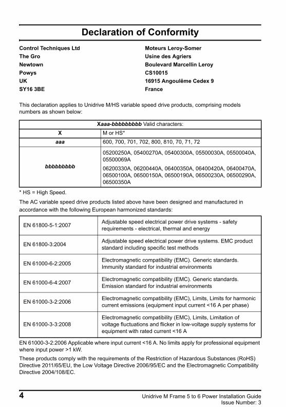
This declaration applies to Unidrive M/HS variable speed drive products, comprising models numbers as shown below:
* HS = High Speed.
The AC variable speed drive products listed above have been designed and manufactured in accordance with the following European harmonized standards:
EN 61000-3-2:2006 Applicable where input current <16 A. No limits apply for professional equipment where input power >1 kW.These products comply with the requirements of the Restriction of Hazardous Substances (RoHS) Directive 2011/65/EU, the Low Voltage Directive 2006/95/EC and the Electromagnetic Compatibility Directive 2004/108/EC.
Control Techniques LtdThe GroNewtownPowysUKSY16 3BE
Moteurs Leroy-SomerUsine des AgriersBoulevard Marcellin LeroyCS1001516915 Angoulême Cedex 9France
Xaaa-bbbbbbbbb Valid characters:X M or HS*
aaa 600, 700, 701, 702, 800, 810, 70, 71, 72
bbbbbbbbb
05200250A, 05400270A, 05400300A, 05500030A, 05500040A, 05500069A06200330A, 06200440A, 06400350A, 06400420A, 06400470A, 06500100A, 06500150A, 06500190A, 06500230A, 06500290A, 06500350A
EN 61800-5-1:2007 Adjustable speed electrical power drive systems - safety requirements - electrical, thermal and energy
EN 61800-3:2004 Adjustable speed electrical power drive systems. EMC product standard including specific test methods
EN 61000-6-2:2005 Electromagnetic compatibility (EMC). Generic standards. Immunity standard for industrial environments
EN 61000-6-4:2007 Electromagnetic compatibility (EMC). Generic standards. Emission standard for industrial environments
EN 61000-3-2:2006 Electromagnetic compatibility (EMC), Limits, Limits for harmonic current emissions (equipment input current <16 A per phase)
EN 61000-3-3:2008Electromagnetic compatibility (EMC), Limits, Limitation of voltage fluctuations and flicker in low-voltage supply systems for equipment with rated current <16 A
4 Unidrive M Frame 5 to 6 Power Installation GuideIssue Number: 3
Unidrive M frame 5 and 6 Installation Guide issue2.book Page 5 Monday, February 2, 2015 10:29 AM
These electronic drive products are intended to be used with appropriate motors, controllers, electrical protection components and other equipment to form complete end products or systems. Compliance with safety and EMC regulations depends upon installing and configuring drives correctly, including using the specified input filters. The drives must be installed only by professional assemblers who are familiar with requirements for safety and EMC. The assembler is responsible for ensuring that the end product or system complies with all the relevant laws in the country where it is to be used. Refer to the Drive User Guide. An EMC Data Sheet is also available giving detailed EMC information.
T. AlexanderControl Techniques Vice President, TechnologyNewtownDate: 9th December 2014
Unidrive M Frame 5 to 6 Power Installation Guide 5Issue Number: 3
Unidrive M frame 5 and 6 Installation Guide issue2.book Page 6 Monday, February 2, 2015 10:29 AM
Declaration of Conformity (including 2006 Machinery Directive)
This declaration applies to the Unidrive M/HS variable speed drive product range, comprising model numbers composed as shown below:
* HS = High SpeedThis declaration relates to these products when used as a safety component of a machine. Only the SAFE TORQUE OFF function may be used for a safety function of a machine. None of the other functions of the drive may be used to carry out a safety function.These products fulfil all the relevant provisions of Directives 2006/42/EC (The Machinery Directive) and 2004/108/EC (The EMC Directive). EC type-examination has been carried out by the following notified body:TÜV Rheinland Industrie Service GmbHAm Grauen SteinD-51105 KÖln
Notified Body identification number: 0035EC type-examination certificate number: 01/205/5270/12
Control Techniques LtdThe GroNewtownPowysUKSY16 3BE
Moteurs Leroy-SomerUsine des AgriersBoulevard Marcellin LeroyCS1001516915 Angoulême Cedex 9France
Maaa-bbbbbbbbb Valid characters:X M or HS*
aaa 600, 700, 701, 702, 800, 810, 70, 71, 72
bbbbbbbbb05200250A, 05400270A, 05400300A, 05500030A, 05500040A, 05500069A06200330A, 06200440A, 06400350A, 06400420A, 06400470A, 06500100A, 06500150A, 06500190A, 06500230A, 06500290A, 06500350A
For more information regarding SAFE TORQUE OFF, refer to section 3.4 in the Drive User Guide.
NOTE
6 Unidrive M Frame 5 to 6 Power Installation GuideIssue Number: 3
Unidrive M frame 5 and 6 Installation Guide issue2.book Page 7 Monday, February 2, 2015 10:29 AM
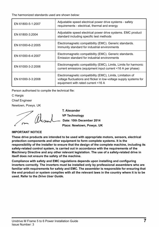
The harmonized standards used are shown below:
Person authorised to compile the technical file:C HargisChief EngineerNewtown, Powys. UK
IMPORTANT NOTICEThese drive products are intended to be used with appropriate motors, sensors, electrical protection components and other equipment to form complete systems. It is the responsibility of the installer to ensure that the design of the complete machine, including its safety-related control system, is carried out in accordance with the requirements of the Machinery Directive and any other relevant legislation. The use of a safety-related drive in itself does not ensure the safety of the machine.Compliance with safety and EMC regulations depends upon installing and configuring inverters correctly. The inverters must be installed only by professional assemblers who are familiar with requirements for safety and EMC. The assembler is responsible for ensuring that the end product or system complies with all the relevant laws in the country where it is to be used. Refer to the Drive User Guide.
EN 61800-5-1:2007 Adjustable speed electrical power drive systems - safety requirements - electrical, thermal and energy
EN 61800-3:2004 Adjustable speed electrical power drive systems. EMC product standard including specific test methods
EN 61000-6-2:2005 Electromagnetic compatibility (EMC). Generic standards. Immunity standard for industrial environments
EN 61000-6-4:2007 Electromagnetic compatibility (EMC). Generic standards. Emission standard for industrial environments
EN 61000-3-2:2006 Electromagnetic compatibility (EMC), Limits, Limits for harmonic current emissions (equipment input current <16 A per phase)
EN 61000-3-3:2008Electromagnetic compatibility (EMC), Limits, Limitation of voltage fluctuations and flicker in low-voltage supply systems for equipment with rated current <16 A
T. AlexanderVP TechnologyDate: 10th December 2014Place: Newtown, Powys. UK
Unidrive M Frame 5 to 6 Power Installation Guide 7Issue Number: 3
Unidrive M frame 5 and 6 Installation Guide issue2.book Page 8 Monday, February 2, 2015 10:29 AM
1 Safety information
1.1 Warnings, Cautions and Notes
1.2 Electrical safety - general warningThe voltages used in the drive can cause severe electrical shock and/or burns, and could be lethal. Extreme care is necessary at all times when working with or adjacent to the drive. Specific warnings are given at the relevant places in this guide.
1.3 System design and safety of personnelThe drive is intended as a component for professional incorporation into complete equipment or a system. If installed incorrectly, the drive may present a safety hazard.The drive uses high voltages and currents, carries a high level of stored electrical energy, and is used to control equipment which can cause injury.Close attention is required to the electrical installation and the system design to avoid hazards either in normal operation or in the event of equipment malfunction. System design, installation, commissioning/start-up and maintenance must be carried out by personnel who have the necessary training and experience. They must read this safety information and this User Guide carefully.The STOP and SAFE TORQUE OFF functions of the drive do not isolate dangerous voltages from the output of the drive or from any external option unit. The supply must be disconnected by an approved electrical isolation device before gaining access to the electrical connections.With the sole exception of the SAFE TORQUE OFF function, none of the drive functions must be used to ensure safety of personnel, i.e. they must not be used for safety-related functions.Careful consideration must be given to the functions of the drive which might result in a hazard, either through their intended behavior or through incorrect operation due to a fault. In any application where a malfunction of the drive or its control system could lead to or allow damage, loss or injury, a risk analysis must be carried out, and where necessary, further measures taken to reduce the risk - for example, an over-speed protection device in case of failure of the speed control, or a fail-safe mechanical brake in case of loss of motor braking.The SAFE TORQUE OFF function may be used in a safety-related application. The system designer is responsible for ensuring that the complete system is safe and designed correctly according to the relevant safety standards.
A Warning contains information which is essential for avoiding a safety hazard.
A Caution contains information which is necessary for avoiding a risk of damage to the product or other equipment.
A Note contains information, which helps to ensure correct operation of the product.
WARNING
CAUTION
NOTE
8 Unidrive M Frame 5 to 6 Power Installation GuideIssue Number: 3
Safety information
Product information
Mechanical installation
Electrical installationTechnical data
UL listing inform
ation
Unidrive M frame 5 and 6 Installation Guide issue2.book Page 9 Monday, February 2, 2015 10:29 AM
1.4 Environmental limitsInstructions in this guide regarding transport, storage, installation and use of the drive must be complied with, including the specified environmental limits. Drives must not be subjected to excessive physical force.
1.5 AccessDrive access must be restricted to authorized personnel only. Safety regulations which apply at the place of use must be complied with.
1.6 Fire protectionThe drive enclosure is not classified as a fire enclosure. A separate fire enclosure must be provided. For further information, refer to the Drive User Guide.
1.7 Compliance with regulationsThe installer is responsible for complying with all relevant regulations, such as national wiring regulations, accident prevention regulations and electromagnetic compatibility (EMC) regulations. Particular attention must be given to the cross-sectional areas of conductors, the selection of fuses or other protection, and protective ground (earth) connections.This guide contains instruction for achieving compliance with specific EMC standards.Within the European Union, all machinery in which this product is used must comply with the following directives:
2006/42/EC: Safety of machinery.2004/108/EC: Electromagnetic Compatibility.
1.8 MotorEnsure the motor is installed in accordance with the manufacturer’s recommendations. Ensure the motor shaft is not exposed.Standard squirrel cage induction motors are designed for single speed operation. If it is intended to use the capability of the drive to run a motor at speeds above its designed maximum, it is strongly recommended that the manufacturer is consulted first.Low speeds may cause the motor to overheat because the cooling fan becomes less effective. The motor should be installed with a protection thermistor. If necessary, an electric forced vent fan should be used.The values of the motor parameters set in the drive affect the protection of the motor. The default values in the drive should not be relied upon.It is essential that the correct value is entered in Pr 00.046 motor rated current. This affects the thermal protection of the motor.
1.9 Mechanical brake controlThe brake control functions are provided to allow well co-ordinated operation of an external brake with the drive. While both hardware and software are designed to high standards of quality and robustness, they are not intended for use as safety functions, i.e. where a fault or failure would result in a risk of injury. In any application where the incorrect operation of the brake release mechanism could result in injury, independent protection devices of proven integrity must also be incorporated.
Unidrive M Frame 5 to 6 Power Installation Guide 9Issue Number: 3
Unidrive M frame 5 and 6 Installation Guide issue2.book Page 10 Monday, February 2, 2015 10:29 AM
1.10 Adjusting parametersSome parameters have a profound effect on the operation of the drive. They must not be altered without careful consideration of the impact on the controlled system. Measures must be taken to prevent unwanted changes due to error or tampering.
1.11 Electrical installation1.11.1 Electric shock risk
The voltages present in the following locations can cause severe electric shock and may be lethal:• AC supply cables and connections• Output cables and connections• Many internal parts of the drive, and external option unitsUnless otherwise indicated, control terminals are single insulated and must not be touched.
1.11.2 Stored chargeThe drive contains capacitors that remain charged to a potentially lethal voltage after the AC supply has been disconnected. If the drive has been energized, the AC supply must be isolated at least ten minutes before work may continue.
10 Unidrive M Frame 5 to 6 Power Installation GuideIssue Number: 3
Safety information
Product information
Mechanical installation
Electrical installationTechnical data
UL listing inform
ation
Unidrive M frame 5 and 6 Installation Guide issue2.book Page 11 Monday, February 2, 2015 10:29 AM
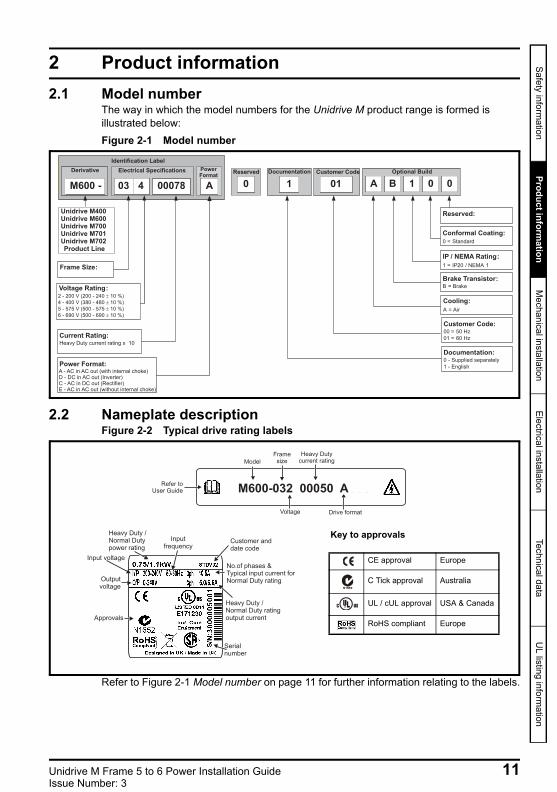
2 Product information2.1 Model number
The way in which the model numbers for the Unidrive M product range is formed is illustrated below:Figure 2-1 Model number
2.2 Nameplate descriptionFigure 2-2 Typical drive rating labels
Refer to Figure 2-1 Model number on page 11 for further information relating to the labels.
Identification Label
Electrical SpecificationsDerivative
Unidrive M400Unidrive M600Unidrive M700Unidrive M701Unidrive M702Product Line
Frame Size:
Voltage Rating:
Current Rating:Heavy Duty current rating x 10
Power Format:
Reserved
0
Optional BuildCustomer Code
01 A B 1 00
Customer Code:00 = 50 Hz
01 = 60 Hz
Reserved:
Conformal Coating:
0 = Standard
IP / NEMA Rating:
1 = IP20 / NEMA 1
Brake Transistor:B = Brake
Cooling:
A = Air
Documentation
1
Documentation:0 - Supplied separately
1 - English
2 - 200 V (200 - 240
- 400 V (380 - 480
- 575 V (500 - 575
- 690 V (500 - 690
10 %)
4
10 %)
5 10 %)
6 10 %)
PowerFormat
M600 - 03 4 00078 A
A - AC in AC out (with internal choke)D - DC in AC out (Inverter)C - AC in DC out (Rectifier)E - AC in AC out (without internal choke)
Refer toUser Guide
Model
Framesize
Voltage
Heavy Dutycurrent rating
Drive format
M600-032 00050 A
Approvals
Input voltage
Outputvoltage
Heavy Duty /Normal Dutypower rating
Customer anddate code
Serialnumber
Inputfrequency
No.of phases &Typical input current forNormal Duty rating
Heavy Duty /Normal Duty ratingoutput current
Key to approvals
CE approval Europe
C Tick approval Australia
UL / cUL approval USA & Canada
RoHS compliant Europe
R
Unidrive M Frame 5 to 6 Power Installation Guide 11Issue Number: 3

Unidrive M frame 5 and 6 Installation Guide issue2.book Page 12 Monday, February 2, 2015 10:29 AM
2.3 Ratings
Table 2-1 200 V drive ratings, cable sizes and fuse ratings
Table 2-2 400 V drive ratings, cable sizes and fuse ratings
Table 2-3 575 V drive ratings, cable sizes and fuse ratings
* These fuses are fast acting.
FusesThe AC supply to the drive must be installed with suitable protection against overload and short-circuits. The following section shows recommended fuse ratings. Failure to observe this requirement will cause risk of fire.WARNING
Nominal cables sizes below are based on the cable installation method B2 (ref: IEC60364-5-52:2001) unless otherwise specified, and are provided as a guide only. Ensure cables used suit local wiring regulations.
NOTE
Model
Max. cont. input
current
FuseNominal cable size
Normal Duty Heavy DutyEuropean USA
IEC UL
Input Output Input Output
Max. cont.
output current
Nom power
@ 230 V
Motor power
@ 230 V
Max. cont.
output current
Nom power
@ 230 V
Motor power
@ 230 V
3ph NomClass
NomClass
A A A mm2 mm2 AWG AWG A kW hp A kW hp
05200250 31 40 gG 40 CC, J or T* 10 10 8 8 30 7.5 10 25 5.5 7.5
06200330 48.8 63gG
60 CC, J or T*
16 16 4 4 50 11 15 33 7.5 1006200440 56.6 63 70 25 25 3 3 58 15 20 44 11 15
Model
Max. cont. input
current
FuseNominal cable size
Normal Duty Heavy DutyEuropean USA
IEC UL
Input Output Input Output
Max. cont.
output current
Nom power
@ 400 V
Motor power
@ 460 V
Max. cont.
output current
Nom power
@ 400 V
Motor power
@ 460 V
3ph NomClass
NomClass
A A A mm2 mm2 AWG AWG A kW hp A kW hp05400270 29 40 gG 35 CC,
J or T*6 6 8 8 30 15 20 27 11 20
05400300 40 35 6 6 8 8 31 30 1506400350 36 63
gR40
HSJ or DFJ
10 10 6 6 38 18.5 25 35 15 2506400420 46 63 50 16 16 4 4 48 22 30 42 18.5 3006400470 60 63 70 25 25 3 3 63 30 40 47 22 30
Model
Max. cont. input
current
FuseNominal cable size
Normal Duty Heavy DutyEuropean USA
IEC UL
Input Output Input Output
Max. cont.
output current
Nom power
@ 575 V
Motor power
@ 575 V
Max. cont.
output current
Nom power
@ 575 V
Motor power
@ 575 V
3ph NomClass
NomClass
A A A mm2 mm2 AWG AWG A kW hp A kW hp05500030 4.3 10
gG10 CC,
J or T*
0.75 0.75 16 16 3.9 2.2 3 3 1.5 205500040 5.7 10 10 1 1 14 14 6.1 4 5 4 2.2 305500069 9.3 20 20 1.5 1.5 14 14 10 5.5 7.5 6.9 4 506500100 13.2 20
gG
20
CC, J or T*
2.5 2.5 14 14 12 7.5 10 10 5.5 7.506500150 18.7 32 25 4 4 10 10 17 11 15 15 7.5 1006500190 24.3 40 30 6 6 10 10 22 15 20 19 11 1506500230 29.4 50 35 10 10 8 8 27 18.5 25 23 15 2006500290 37.1 50 40 10 10 6 6 34 22 30 29 18.5 2506500350 46.9 63 50 16 16 6 6 43 30 40 35 22 30
12 Unidrive M Frame 5 to 6 Power Installation GuideIssue Number: 3
Safety information
Product information
Mechanical installation
Electrical installationTechnical data
UL listing inform
ation
Unidrive M frame 5 and 6 Installation Guide issue2.book Page 13 Monday, February 2, 2015 10:29 AM
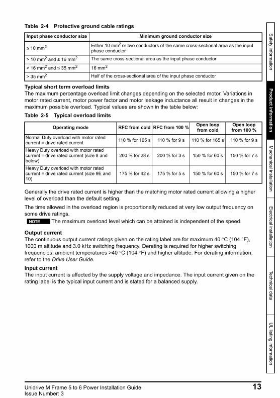
Table 2-4 Protective ground cable ratings
Typical short term overload limitsThe maximum percentage overload limit changes depending on the selected motor. Variations in motor rated current, motor power factor and motor leakage inductance all result in changes in the maximum possible overload. Typical values are shown in the table below:Table 2-5 Typical overload limits
Generally the drive rated current is higher than the matching motor rated current allowing a higher level of overload than the default setting.The time allowed in the overload region is proportionally reduced at very low output frequency on some drive ratings.
Output currentThe continuous output current ratings given on the rating label are for maximum 40 °C (104 °F), 1000 m altitude and 3.0 kHz switching frequency. Derating is required for higher switching frequencies, ambient temperatures >40 °C (104 °F) and higher altitude. For derating information, refer to the Drive User Guide.Input currentThe input current is affected by the supply voltage and impedance. The input current given on the rating label is the typical input current and is stated for a balanced supply.
Input phase conductor size Minimum ground conductor size
≤ 10 mm2 Either 10 mm2 or two conductors of the same cross-sectional area as the input phase conductor
> 10 mm2 and ≤ 16 mm2 The same cross-sectional area as the input phase conductor
> 16 mm2 and ≤ 35 mm2 16 mm2
> 35 mm2 Half of the cross-sectional area of the input phase conductor
Operating mode RFC from cold RFC from 100 % Open loop from cold
Open loop from 100 %
Normal Duty overload with motor rated current = drive rated current 110 % for 165 s 110 % for 9 s 110 % for 165 s 110 % for 9 s
Heavy Duty overload with motor rated current = drive rated current (size 8 and below)
200 % for 28 s 200 % for 3 s 150 % for 60 s 150 % for 7 s
Heavy Duty overload with motor rated current = drive rated current (size 9E and 10)
175 % for 42 s 175 % for 5 s 150 % for 60 s 150 % for 7 s
The maximum overload level which can be attained is independent of the speed. NOTE
Unidrive M Frame 5 to 6 Power Installation Guide 13Issue Number: 3
Unidrive M frame 5 and 6 Installation Guide issue2.book Page 14 Monday, February 2, 2015 10:29 AM
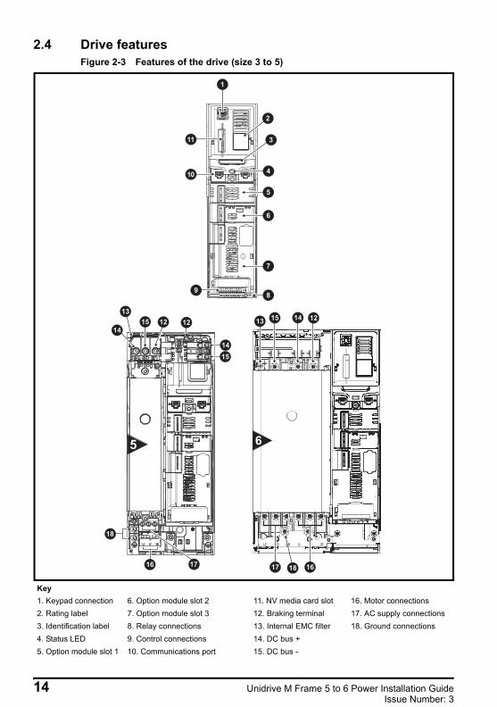
2.4 Drive features Figure 2-3 Features of the drive (size 3 to 5)
Key1. Keypad connection 6. Option module slot 2 11. NV media card slot 16. Motor connections2. Rating label 7. Option module slot 3 12. Braking terminal 17. AC supply connections3. Identification label 8. Relay connections 13. Internal EMC filter 18. Ground connections4. Status LED 9. Control connections 14. DC bus +5. Option module slot 1 10. Communications port 15. DC bus -
1514
15 12 12
15
1514
18
1716
15 14 12
17 1618
1
2
3
4
5
6
7
89
10
11
13
13
14 Unidrive M Frame 5 to 6 Power Installation GuideIssue Number: 3
Safety information
Product information
Mechanical installation
Electrical installationTechnical data
UL listing inform
ation
Unidrive M frame 5 and 6 Installation Guide issue2.book Page 15 Monday, February 2, 2015 10:29 AM
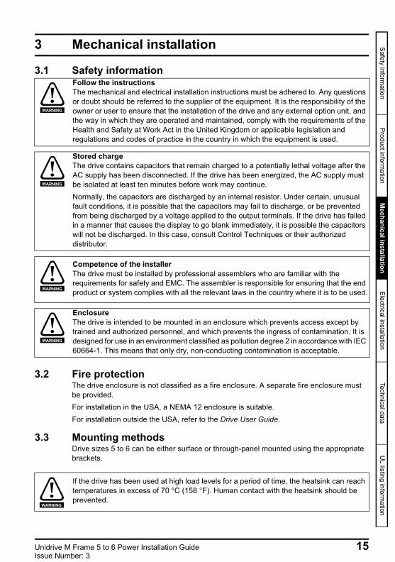
3 Mechanical installation
3.1 Safety information
3.2 Fire protectionThe drive enclosure is not classified as a fire enclosure. A separate fire enclosure must be provided.For installation in the USA, a NEMA 12 enclosure is suitable.For installation outside the USA, refer to the Drive User Guide.
3.3 Mounting methodsDrive sizes 5 to 6 can be either surface or through-panel mounted using the appropriate brackets.
Follow the instructionsThe mechanical and electrical installation instructions must be adhered to. Any questions or doubt should be referred to the supplier of the equipment. It is the responsibility of the owner or user to ensure that the installation of the drive and any external option unit, and the way in which they are operated and maintained, comply with the requirements of the Health and Safety at Work Act in the United Kingdom or applicable legislation and regulations and codes of practice in the country in which the equipment is used.
WARNING
Stored chargeThe drive contains capacitors that remain charged to a potentially lethal voltage after the AC supply has been disconnected. If the drive has been energized, the AC supply must be isolated at least ten minutes before work may continue.Normally, the capacitors are discharged by an internal resistor. Under certain, unusual fault conditions, it is possible that the capacitors may fail to discharge, or be prevented from being discharged by a voltage applied to the output terminals. If the drive has failed in a manner that causes the display to go blank immediately, it is possible the capacitors will not be discharged. In this case, consult Control Techniques or their authorized distributor.
WARNING
Competence of the installerThe drive must be installed by professional assemblers who are familiar with the requirements for safety and EMC. The assembler is responsible for ensuring that the end product or system complies with all the relevant laws in the country where it is to be used.WARNING
EnclosureThe drive is intended to be mounted in an enclosure which prevents access except by trained and authorized personnel, and which prevents the ingress of contamination. It is designed for use in an environment classified as pollution degree 2 in accordance with IEC 60664-1. This means that only dry, non-conducting contamination is acceptable.
WARNING
If the drive has been used at high load levels for a period of time, the heatsink can reach temperatures in excess of 70 °C (158 °F). Human contact with the heatsink should be prevented.
WARNING
Unidrive M Frame 5 to 6 Power Installation Guide 15Issue Number: 3
Unidrive M frame 5 and 6 Installation Guide issue2.book Page 16 Monday, February 2, 2015 10:29 AM
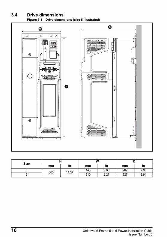
3.4 Drive dimensionsFigure 3-1 Drive dimensions (size 5 illustrated)
H
WD
Size H W Dmm in mm in mm in
5365 14.37
143 5.63 202 7.956 210 8.27 227 8.94
16 Unidrive M Frame 5 to 6 Power Installation GuideIssue Number: 3
Safety information
Product information
Mechanical installation
Electrical installationTechnical data
UL listing inform
ation
Unidrive M frame 5 and 6 Installation Guide issue2.book Page 17 Monday, February 2, 2015 10:29 AM
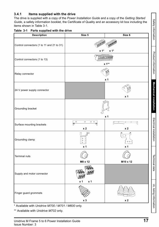
3.4.1 Items supplied with the driveThe drive is supplied with a copy of the Power Installation Guide and a copy of the Getting Started Guide, a safety information booklet, the Certificate of Quality and an accessory kit box including the items shown in Table 3-1.Table 3-1 Parts supplied with the drive
* Available with Unidrive M700 / M701 / M600 only.** Available with Unidrive M702 only.
Description Size 5 Size 6
Control connectors (1 to 11 and 21 to 31)
x 1* x 1*
Control connectors (1 to 13)
x 1**
Relay connector
x 1
24 V power supply connector
x 1
Grounding bracket
x 1
Surface mounting bracketsx 2 x 2
Grounding clamp
x 1 x 1
Terminal nuts
M8 x 12 M10 x 12
Supply and motor connector
x 1 x 1
Finger guard grommets
x 3 x 2
51 52
Unidrive M Frame 5 to 6 Power Installation Guide 17Issue Number: 3
Unidrive M frame 5 and 6 Installation Guide issue2.book Page 18 Monday, February 2, 2015 10:29 AM
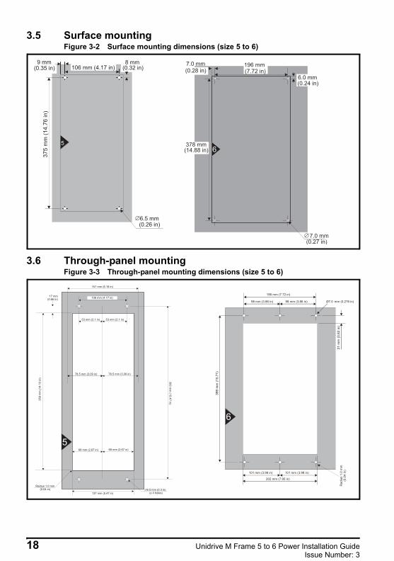
3.5 Surface mountingFigure 3-2 Surface mounting dimensions (size 5 to 6)
3.6 Through-panel mountingFigure 3-3 Through-panel mounting dimensions (size 5 to 6)
9 mm(0.35 in)
8 mm(0.32 in)
375
mm
(14.7
6in
)
6.5 mm(0.26 in)
5
106 mm (4.17 in)
378 mm(14.88 in)
196 mm(7.72 in)
6.0 mm(0.24 in)
7.0 mm(0.27 in)
7.0 mm
(0.28 in)
6
5
6
18 Unidrive M Frame 5 to 6 Power Installation GuideIssue Number: 3
Safety information
Product information
Mechanical installation
Electrical installationTechnical data
UL listing inform
ation
Unidrive M frame 5 and 6 Installation Guide issue2.book Page 19 Monday, February 2, 2015 10:29 AM
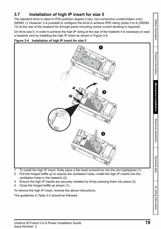
3.7 Installation of high IP insert for size 5The standard drive is rated to IP20 pollution degree 2 (dry, non-conductive contamination only) (NEMA 1). However, it is possible to configure the drive to achieve IP65 rating (sizes 5 to 6) (NEMA 12) at the rear of the heatsink for through-panel mounting (some current derating is required).On drive size 5, in order to achieve the high IP rating at the rear of the heatsink it is necessary to seal a heatsink vent by installing the high IP insert as shown in Figure 3-4.Figure 3-4 Installation of high IP insert for size 5
1. To install the high IP insert, firstly place a flat head screwdriver into the slot highlighted (1).2. Pull the hinged baffle up to expose the ventilation holes, install the high IP inserts into the
ventilation holes in the heatsink (2).3. Ensure the high IP inserts are securely installed by firmly pressing them into place (3).4. Close the hinged baffle as shown (1).To remove the high IP insert, reverse the above instructions.The guidelines in Table 3-2 should be followed.
1
2
3
Unidrive M Frame 5 to 6 Power Installation Guide 19Issue Number: 3
Unidrive M frame 5 and 6 Installation Guide issue2.book Page 20 Monday, February 2, 2015 10:29 AM
Table 3-2 Environment considerations
A current derating must be applied to the drive if the high IP insert is installed. Derating information is provided in the Drive User Guide. Failure to do so may result in nuisance tripping.
3.8 Terminal size and torque settingsTable 3-3 Drive control and relay terminal data
Table 3-4 Drive power terminal data
3.8.1 Internal braking resistorSize 5 has been designed with an optional space-saving heatsink mounted resistor. The resistor can be installed within the heatsink fins of the drive. When the heatsink resistor is used, an external thermal protection device is not required as the resistor is designed such that it will fail safely under any fault conditions. The in-built software overload protection is set-up at default to protect the resistor. The resistor is rated to IP54 (NEMA 12).
Environment High IP insert CommentsClean Not installedDry, dusty (non-conductive) Installed
Regular cleaning recommendedDry, dusty (conductive) InstalledIP65 compliance Installed
Model Connection type Torque settingAll Plug-in terminal block 0.5 N m (0.4 lb ft)
Model sizeAC terminals DC and braking Ground terminal
Recommended
5Plug-in terminal block
1.8 N m (1.3 lb ft)T20 Torx (M4) /
M4 Nut (7 mm AF) M5 Nut (8 mm AF)
1.5 N m (1.1 lb ft) 1.5 N m (1.1 lb ft) 2.0 N m (1.47 Ib ft)
6M6 Nut (10 mm AF)6.0 N m (4.42 Ib ft)
NOTE
20 Unidrive M Frame 5 to 6 Power Installation GuideIssue Number: 3
Safety information
Product information
Mechanical installation
Electrical installationTechnical data
UL listing inform
ation
Unidrive M frame 5 and 6 Installation Guide issue2.book Page 21 Monday, February 2, 2015 10:29 AM
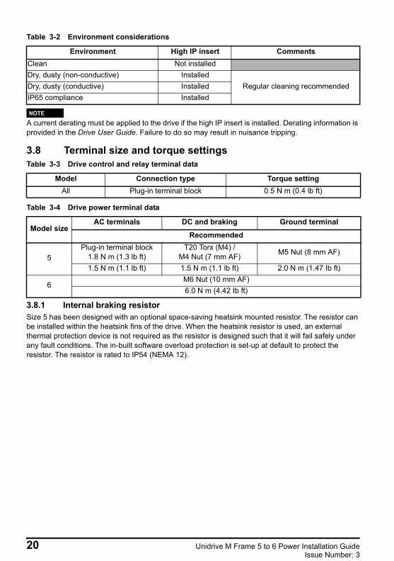
Figure 3-5 Brake resistor installation on size 5
1. Remove the terminal covers.2. Remove the brake resistor bung from the hole in the chassis, the closed end of the bung will
need to be pierced so that the cable has access to be routed through.3. Feed brake resistor bung onto outer insulation of brake resistor cable. The wider end of the bung
should be inserted first. The Narrow end should align with end of insulation.4. Install the braking resistor to the heatsink using the captive screws. The screws should be tighten to a
maximum torque of 2 N m (1.5 lb ft).5. Route the cables through the provided hole at the rear of the heatsink as shown in Figure 3-5
and take the cable out from the front side of the drive. Ensure the cables are routed between the fins of the heatsink, and the cables are not trapped between the heatsink fins and the resistor.
6. Crimp the cable ends and make appropriate connections. The brake terminals must be tightened to a maximum torque of 2 N m (1.5 Ib ft).
7. Replace the terminal covers on the drive, tighten to a maximum torque of 1 N m (0.7 lb ft).
3.8.2 External brake resistor External brake resistors are available from Control Techniques for drive sizes 5 to 6. They can be mounted in the enclosure as per mounting recommendation in Figure 3-9 Enclosure layout on page 23 using mounting brackets part number 6541-0187-00. Figure 3-6 below shows the brake resistor mounted on the mounting bracket. Two M4 screws and nuts (2) can be used to fix the brake resistor to the mounting bracket. One M4 nut with washer (1) is provided to use for the ground connection. The brake resistor is equipped with a thermal switch, the thermal switch should be integrated in the control circuit by the user.
Unidrive M Frame 5 to 6 Power Installation Guide 21Issue Number: 3
Unidrive M frame 5 and 6 Installation Guide issue2.book Page 22 Monday, February 2, 2015 10:29 AM
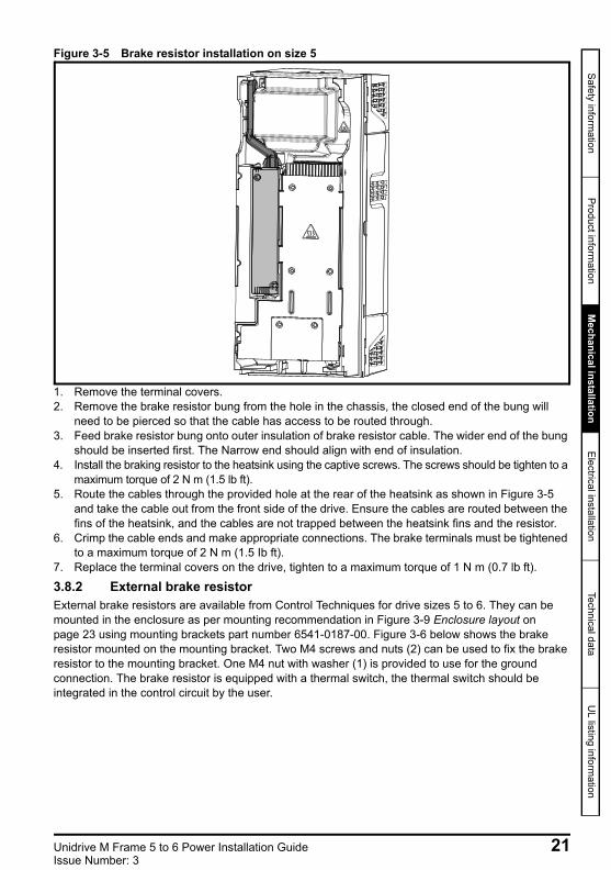
Figure 3-6 Brake resistor with the mounting bracket
1. Ground connection (1 x M4 nut and washer).2. Attaching the brake resistor to the mounting bracket (using 2 x M4 screws and nuts).
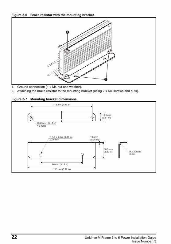
Figure 3-7 Mounting bracket dimensions
1
2
118 mm (4.65 in)
15.5 mm(0.61 in)
4.5 mm (0.18 in)x 2 holes
1.5 mm(0.06 in)
30.5 mm(1.20 in)
80 mm (3.15 in)
130 mm (5.12 in)
4.5 x 6 mm (0.18 in)x 2 holes
R = 1.5 mm(0.06)
22 Unidrive M Frame 5 to 6 Power Installation GuideIssue Number: 3
Safety information
Product information
Mechanical installation
Electrical installationTechnical data
UL listing inform
ation
Unidrive M frame 5 and 6 Installation Guide issue2.book Page 23 Monday, February 2, 2015 10:29 AM
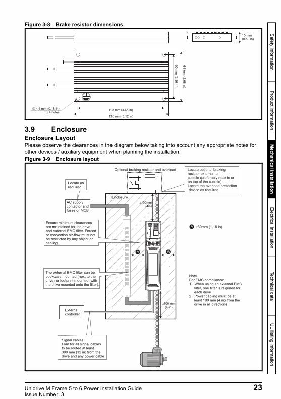
Figure 3-8 Brake resistor dimensions
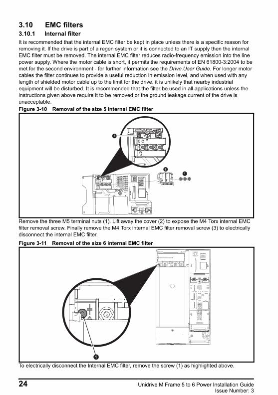
3.9 EnclosureEnclosure LayoutPlease observe the clearances in the diagram below taking into account any appropriate notes for other devices / auxiliary equipment when planning the installation.Figure 3-9 Enclosure layout
60
mm
(2.3
6in
)
68
mm
(2.6
8in
)
118 mm (4.65 in)
130 mm (5.12 in)
4.5 mm (0.18 in)x 4 holes
15 mm(0.59 in)
100 mm(4 in)
Enclosure
AC supplycontactor andfuses or MCB
Locate asrequiredLocate asrequired
Externalcontroller
Signal cablesPlan for all signal cablesto be routed at least300 mm (12 in) from thedrive and any power cable
Ensure minimum clearancesare maintained for the driveand external EMC filter. Forcedor convection air-flow must notbe restricted by any object orcabling
100mm(4in)
Optional braking resistor and overload Locate optional brakingresistor external tocubicle (preferably near to oron top of the cubicle).Locate the overload protectiondevice as required
The external EMC filter can bebookcase mounted (next to thedrive) or footprint mounted (withthe drive mounted onto the filter).
NoteFor EMC compliance:1) When using an external EMC
filter, one filter is required foreach drive
2) Power cabling must be atleast 100 mm (4 in) from thedrive in all directions
A 30mm (1.18 in)
A A
Unidrive M Frame 5 to 6 Power Installation Guide 23Issue Number: 3
Unidrive M frame 5 and 6 Installation Guide issue2.book Page 24 Monday, February 2, 2015 10:29 AM
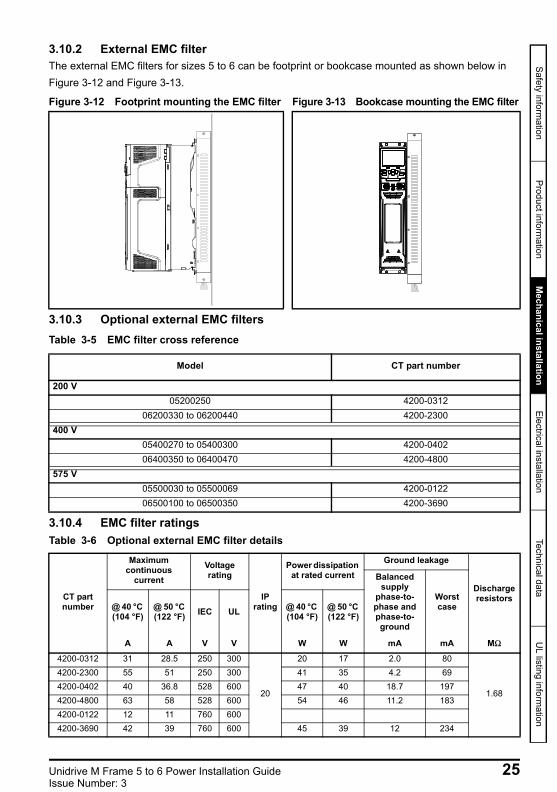
3.10 EMC filters3.10.1 Internal filterIt is recommended that the internal EMC filter be kept in place unless there is a specific reason for removing it. If the drive is part of a regen system or it is connected to an IT supply then the internal EMC filter must be removed. The internal EMC filter reduces radio-frequency emission into the line power supply. Where the motor cable is short, it permits the requirements of EN 61800-3:2004 to be met for the second environment - for further information see the Drive User Guide. For longer motor cables the filter continues to provide a useful reduction in emission level, and when used with any length of shielded motor cable up to the limit for the drive, it is unlikely that nearby industrial equipment will be disturbed. It is recommended that the filter be used in all applications unless the instructions given above require it to be removed or the ground leakage current of the drive is unacceptable.Figure 3-10 Removal of the size 5 internal EMC filter
Remove the three M5 terminal nuts (1). Lift away the cover (2) to expose the M4 Torx internal EMC filter removal screw. Finally remove the M4 Torx internal EMC filter removal screw (3) to electrically disconnect the internal EMC filter.Figure 3-11 Removal of the size 6 internal EMC filter
To electrically disconnect the Internal EMC filter, remove the screw (1) as highlighted above.
1
2
3
1
24 Unidrive M Frame 5 to 6 Power Installation GuideIssue Number: 3
Safety information
Product information
Mechanical installation
Electrical installationTechnical data
UL listing inform
ation
Unidrive M frame 5 and 6 Installation Guide issue2.book Page 25 Monday, February 2, 2015 10:29 AM
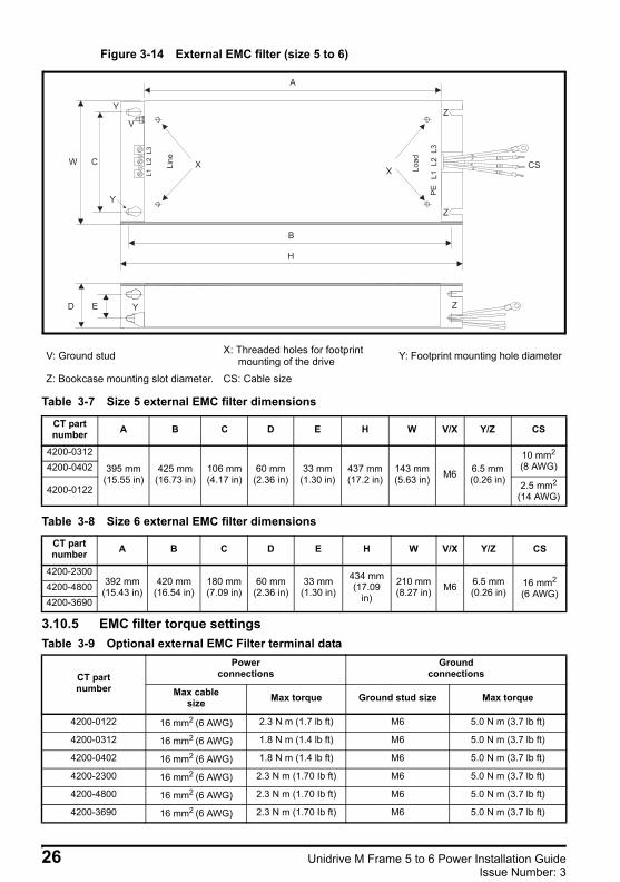
3.10.2 External EMC filterThe external EMC filters for sizes 5 to 6 can be footprint or bookcase mounted as shown below in Figure 3-12 and Figure 3-13.
3.10.3 Optional external EMC filtersTable 3-5 EMC filter cross reference
3.10.4 EMC filter ratingsTable 3-6 Optional external EMC filter details
Figure 3-12 Footprint mounting the EMC filter Figure 3-13 Bookcase mounting the EMC filter
Model CT part number
200 V05200250 4200-0312
06200330 to 06200440 4200-2300400 V
05400270 to 05400300 4200-040206400350 to 06400470 4200-4800
575 V05500030 to 05500069 4200-012206500100 to 06500350 4200-3690
CT part number
Maximum continuous
current Voltage rating
IP rating
Power dissipation at rated current
Ground leakage
Discharge resistors
Balanced supply
phase-to-phase and phase-to-ground
Worst case@ 40 °C
(104 °F)@ 50 °C (122 °F) IEC UL @ 40 °C
(104 °F)@ 50 °C (122 °F)
A A V V W W mA mA MΩ
4200-0312 31 28.5 250 300
20
20 17 2.0 80
1.68
4200-2300 55 51 250 300 41 35 4.2 694200-0402 40 36.8 528 600 47 40 18.7 1974200-4800 63 58 528 600 54 46 11.2 1834200-0122 12 11 760 6004200-3690 42 39 760 600 45 39 12 234
Unidrive M Frame 5 to 6 Power Installation Guide 25Issue Number: 3
Unidrive M frame 5 and 6 Installation Guide issue2.book Page 26 Monday, February 2, 2015 10:29 AM
Figure 3-14 External EMC filter (size 5 to 6)
Table 3-7 Size 5 external EMC filter dimensions
Table 3-8 Size 6 external EMC filter dimensions
3.10.5 EMC filter torque settingsTable 3-9 Optional external EMC Filter terminal data
V: Ground stud X: Threaded holes for footprint mounting of the drive Y: Footprint mounting hole diameter
Z: Bookcase mounting slot diameter. CS: Cable size
CT part number A B C D E H W V/X Y/Z CS
4200-0312
395 mm(15.55 in)
425 mm(16.73 in)
106 mm(4.17 in)
60 mm(2.36 in)
33 mm(1.30 in)
437 mm(17.2 in)
143 mm(5.63 in) M6 6.5 mm
(0.26 in)
10 mm2
(8 AWG)4200-0402
4200-0122 2.5 mm2
(14 AWG)
CT part number A B C D E H W V/X Y/Z CS
4200-2300392 mm
(15.43 in)420 mm
(16.54 in)180 mm(7.09 in)
60 mm(2.36 in)
33 mm(1.30 in)
434 mm(17.09
in)
210 mm(8.27 in) M6 6.5 mm
(0.26 in)16 mm2
(6 AWG)4200-48004200-3690
CT part number
Power connections
Ground connections
Max cable size Max torque Ground stud size Max torque
4200-0122 16 mm2 (6 AWG) 2.3 N m (1.7 lb ft) M6 5.0 N m (3.7 lb ft)
4200-0312 16 mm2 (6 AWG) 1.8 N m (1.4 lb ft) M6 5.0 N m (3.7 lb ft)
4200-0402 16 mm2 (6 AWG) 1.8 N m (1.4 lb ft) M6 5.0 N m (3.7 lb ft)
4200-2300 16 mm2 (6 AWG) 2.3 N m (1.70 Ib ft) M6 5.0 N m (3.7 lb ft)
4200-4800 16 mm2 (6 AWG) 2.3 N m (1.70 Ib ft) M6 5.0 N m (3.7 lb ft)
4200-3690 16 mm2 (6 AWG) 2.3 N m (1.70 Ib ft) M6 5.0 N m (3.7 lb ft)
YED Z
L1'
L2'
L3'
X X
Y
V
Y
A
B
H
CW
Z
Z
CSLin
e
Load
PE
L1
L2
L3
L1
L2
L3
26 Unidrive M Frame 5 to 6 Power Installation GuideIssue Number: 3
Safety information
Product information
Mechanical installation
Electrical installationTechnical data
UL listing inform
ation
Unidrive M frame 5 and 6 Installation Guide issue2.book Page 27 Monday, February 2, 2015 10:29 AM
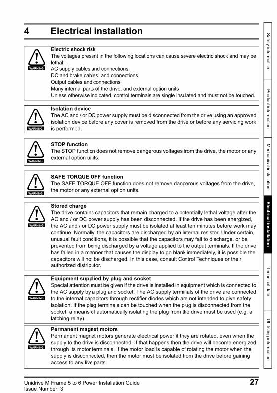
4 Electrical installation
Electric shock riskThe voltages present in the following locations can cause severe electric shock and may be lethal:AC supply cables and connectionsDC and brake cables, and connectionsOutput cables and connectionsMany internal parts of the drive, and external option unitsUnless otherwise indicated, control terminals are single insulated and must not be touched.
WARNING
Isolation device The AC and / or DC power supply must be disconnected from the drive using an approved isolation device before any cover is removed from the drive or before any servicing work is performed.WARNING
STOP functionThe STOP function does not remove dangerous voltages from the drive, the motor or any external option units.
WARNING
SAFE TORQUE OFF functionThe SAFE TORQUE OFF function does not remove dangerous voltages from the drive, the motor or any external option units.
WARNING
Stored chargeThe drive contains capacitors that remain charged to a potentially lethal voltage after the AC and / or DC power supply has been disconnected. If the drive has been energized, the AC and / or DC power supply must be isolated at least ten minutes before work may continue. Normally, the capacitors are discharged by an internal resistor. Under certain, unusual fault conditions, it is possible that the capacitors may fail to discharge, or be prevented from being discharged by a voltage applied to the output terminals. If the drive has failed in a manner that causes the display to go blank immediately, it is possible the capacitors will not be discharged. In this case, consult Control Techniques or their authorized distributor.
WARNING
Equipment supplied by plug and socketSpecial attention must be given if the drive is installed in equipment which is connected to the AC supply by a plug and socket. The AC supply terminals of the drive are connected to the internal capacitors through rectifier diodes which are not intended to give safety isolation. If the plug terminals can be touched when the plug is disconnected from the socket, a means of automatically isolating the plug from the drive must be used (e.g. a latching relay).
Permanent magnet motorsPermanent magnet motors generate electrical power if they are rotated, even when the supply to the drive is disconnected. If that happens then the drive will become energized through its motor terminals. If the motor load is capable of rotating the motor when the supply is disconnected, then the motor must be isolated from the drive before gaining access to any live parts.
WARNING
WARNING
Unidrive M Frame 5 to 6 Power Installation Guide 27Issue Number: 3
Unidrive M frame 5 and 6 Installation Guide issue2.book Page 28 Monday, February 2, 2015 10:29 AM
4.1 Supply typesAll drives are suitable for use on any supply type i.e TN-S, TN-C-S, TT and IT.Supplies with voltage up to 600 V may have grounding at any potential, i.e. neutral, centre or corner (“grounded delta”)
Supplies with voltage above 600 V may not have corner grounding
Drives are suitable for use on supplies of installation category III and lower, according to IEC 60664-1. This means they may be connected permanently to the supply at its origin in a building, but for outdoor installation additional over-voltage suppression (transient voltage surge suppression) must be provided to reduce category IV to category III.
4.2 Supply requirementsAC supply voltage:
200 V drive: 200 V to 240 V ±10 %400 V drive: 380 V to 480 V ±10 %575 V drive: 500 V to 575 V ±10 %
Number of phases: 3Maximum supply imbalance: 2 % negative phase sequence (equivalent to 3 % voltage imbalance between phases).Frequency range: 45 to 66 HzFor UL compliance only, the maximum supply symmetrical fault current must be limited to 100 kA
Table 4-1 Supply fault current used to calculate maximum input currents
4.3 Motor requirementsNo. of phases: 3Maximum voltage:
200 V drive: 240 V 400 V drive: 480 V 575 V drive: 575 V
If the drive is to be used on an IT (ungrounded) supply, refer to the Drive User Guide for more information.
NOTE
Model Symmetrical fault level (kA)All 100
28 Unidrive M Frame 5 to 6 Power Installation GuideIssue Number: 3
Safety information
Product information
Mechanical installation
Electrical installationTechnical data
UL listing inform
ation
Unidrive M frame 5 and 6 Installation Guide issue2.book Page 29 Monday, February 2, 2015 10:29 AM
4.4 RatingsSee section 2.3 Ratings on page 12.Maximum continuous input currentThe values of maximum continuous input current are given to aid the selection of cables and fuses. These values are stated for the worst case condition with the unusual combination of stiff supply with high imbalance. The value stated for the maximum continuous input current would only be seen in one of the input phases. The current in the other two phases would be significantly lower.The values of maximum input current are stated for a supply with a 2 % negative phase-sequence imbalance and rated at the maximum supply fault current given in section 2.3 Ratings on page 12.The nominal cable sizes given in section 2.3 Ratings on page 12 are only a guide. Refer to local wiring regulations for the correct size of cables. In some cases a larger cable is required to avoid excessive voltage drop.
A fuse or other protection must be included in all live connections to the AC supply.Fuse types The fuse voltage rating must be suitable for the drive supply voltage.
The nominal output cable sizes in section 2.3 Ratings on page 12 assume that the motor maximum current matches that of the drive. Where a motor of reduced rating is used the cable rating may be chosen to match that of the motor. To ensure that the motor and cable are protected against over-load, the drive must be programmed with the correct motor rated current.
NOTE
FusesThe AC supply to the drive must be installed with suitable protection against overload and short-circuits. Nominal fuse ratings are shown in section 2.3 Ratings on page 12. Failure to observe this requirement will cause risk of fire.WARNING
Unidrive M Frame 5 to 6 Power Installation Guide 29Issue Number: 3
Unidrive M frame 5 and 6 Installation Guide issue2.book Page 30 Monday, February 2, 2015 10:29 AM
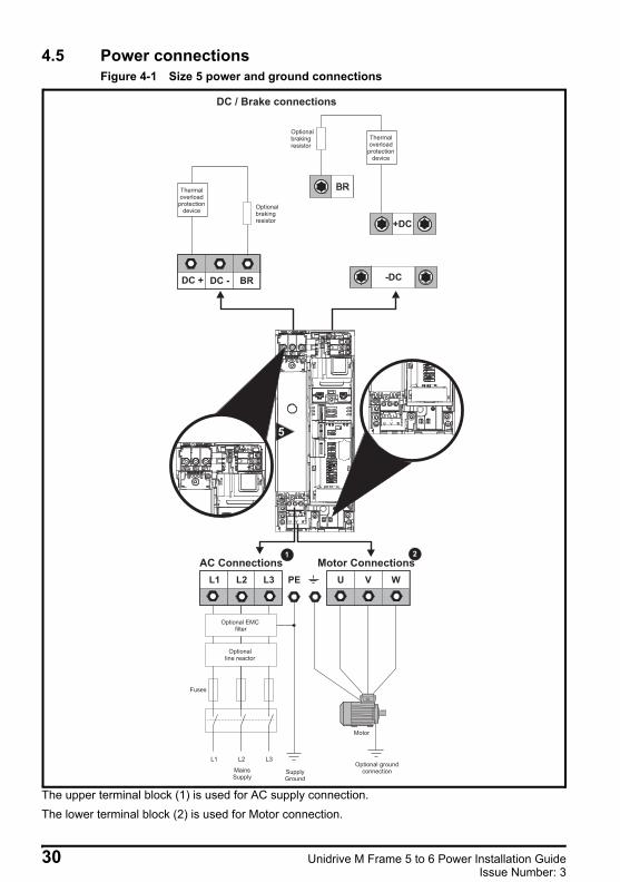
4.5 Power connectionsFigure 4-1 Size 5 power and ground connections
The upper terminal block (1) is used for AC supply connection.The lower terminal block (2) is used for Motor connection.
Optionalbrakingresistor
Thermaloverload
protectiondevice
BR
+DC
-DC
DC / Brake connections
BR
Optionalbrakingresistor
Thermaloverloadprotection
device
DC -DC +
L1 L2
L2L1 L3 U V W
Optional EMCfilter
Optionalline reactor
Fuses
L3
MainsSupply
Motor
Optional groundconnectionSupply
Ground
PE
AC Connections Motor Connections1 2
30 Unidrive M Frame 5 to 6 Power Installation GuideIssue Number: 3
Safety information
Product information
Mechanical installation
Electrical installationTechnical data
UL listing inform
ation
Unidrive M frame 5 and 6 Installation Guide issue2.book Page 31 Monday, February 2, 2015 10:29 AM
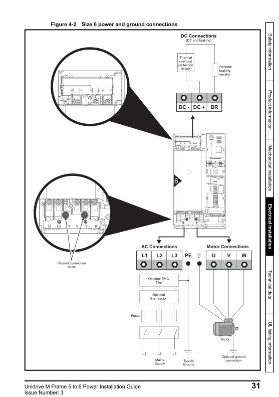
Figure 4-2 Size 6 power and ground connections
L1 L2
L2L1 L3 U V W
Optional EMCfilter
Optionalline reactor
Fuses
L3
MainsSupply
Motor
Optional groundconnectionSupply
Ground
PE
AC Connections
BR
Optionalbrakingresistor
Thermaloverloadprotection
device
DC - DC +
DC Connections(DC and braking)
Motor Connections
6
Ground connectionstuds
Unidrive M Frame 5 to 6 Power Installation Guide 31Issue Number: 3
Unidrive M frame 5 and 6 Installation Guide issue2.book Page 32 Monday, February 2, 2015 10:29 AM
4.6 Ground connections
The drive must be connected to the system ground of the AC supply. The ground wiring must conform to local regulations and codes of practice.
On size 5, the supply and motor ground connections are made using the M5 studs located near the plug-in power connector. Refer to Figure 4-1.On a size 6, the supply and motor ground connections are made using the M6 studs located above the supply and motor terminals. Refer to Figure 4-2.
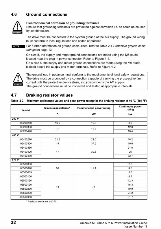
4.7 Braking resistor valuesTable 4-2 Minimum resistance values and peak power rating for the braking resistor at 40 °C (104 °F)
* Resistor tolerance: ±10 %
Electrochemical corrosion of grounding terminalsEnsure that grounding terminals are protected against corrosion i.e. as could be caused by condensation.
WARNING
For further information on ground cable sizes, refer to Table 2-4 Protective ground cable ratings on page 13.
NOTE
The ground loop impedance must conform to the requirements of local safety regulations. The drive must be grounded by a connection capable of carrying the prospective fault current until the protective device (fuse, etc.) disconnects the AC supply. The ground connections must be inspected and tested at appropriate intervals.
ModelMinimum resistance * Instantaneous power rating Continuous power
rating
Ω kW kW
200 V05200250 16.5 10.3 8.606200330
8.6 19.712.6
06200440 16.4400 V
05400270 31.5 21.5 16.205400300 18 37.5 19.606400350
17 39.821.6
06400420 2506400470 32.7
575 V05500030
80 12.12.6
05500040 4.605500069 6.506500100
13 74
8.706500150 12.306500190 16.306500230 19.906500290 24.206500350 31.7
WARNING
32 Unidrive M Frame 5 to 6 Power Installation GuideIssue Number: 3
Safety information
Product information
Mechanical installation
Electrical installationTechnical data
UL listing inform
ation
Unidrive M frame 5 and 6 Installation Guide issue2.book Page 33 Monday, February 2, 2015 10:29 AM
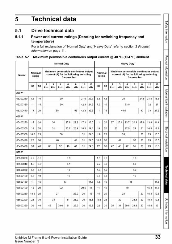
5 Technical data5.1 Drive technical data5.1.1 Power and current ratings (Derating for switching frequency and
temperature)For a full explanation of ‘Normal Duty’ and ‘Heavy Duty’ refer to section 2 Product information on page 11.
Table 5-1 Maximum permissible continuous output current @ 40 °C (104 °F) ambient
Model
Normal Duty Heavy Duty
Nominal rating
Maximum permissible continuous output current (A) for the following switching
frequencies
Nominal rating
Maximum permissible continuous output current (A) for the following switching
frequencies
kW hp 2kHz
3kHz
4kHz
6kHz
8kHz
12kHz
16kHz kW hp 2
kHz3
kHz4
kHz6
kHz8
kHz12
kHz16
kHz
200 V
05200250 7.5 10 30 27.6 23.7 5.5 7.5 25 24.8 21.5 18.8
06200330 11 15 50 42.3 24.5 7.5 10 33.0 32 27
06200440 15 20 58 53 42.3 32.5 11 15 44.0 40 33 27.3
400 V
05400270 15 20 30 25.8 22.2 17.1 13.5 11 20 27 25.4 23.7 20.3 17.6 13.8 11.1
05400300 15 20 31 30.7 26.4 18.3 14.1 15 20 30 27.9 24 21 14.9 12.2
06400350 18.5 25 38 31 24.3 15 25 35 30 23 18.5
06400420 22 30 48 41 31 24.5 18.5 30 42 35 30 23 18.5
06400470 30 40 63 57 48 41 31 24.5 22 30 47 46 42 35 30 23 18.5
575 V
05500030 2.2 3.0 3.9 1.5 2.0 3.0
05500040 4.0 5.0 6.1 2.2 3.0 4.0
05500069 5.5 7.5 10 4.0 5.0 6.9
06500100 7.5 10 12 5.5 7.5 10
06500150 11 15 17 14.8 7.5 10 15 11.6
06500190 15 20 22 20.5 15 11 15 19 15.4 11.6
06500230 18.5 25 27 26.2 20 16 15 20 23 20 15.4 12.8
06500290 22 30 34 31 26.2 20 16.8 18.5 25 29 23.8 20 15.4 12.8
06500350 30 40 43 39.6 31 26.2 20 16.8 22 30 35 34 29.8 23.8 20 15.4 13
Unidrive M Frame 5 to 6 Power Installation Guide 33Issue Number: 3
Unidrive M frame 5 and 6 Installation Guide issue2.book Page 34 Monday, February 2, 2015 10:29 AM
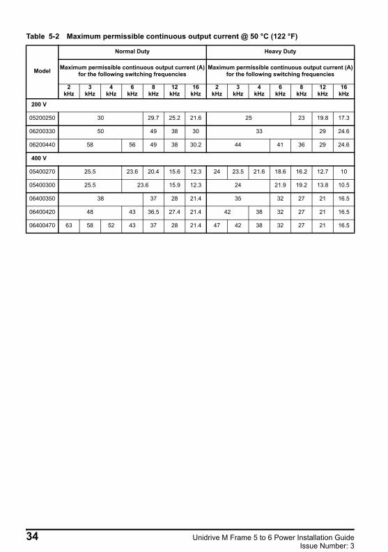
Table 5-2 Maximum permissible continuous output current @ 50 °C (122 °F)
Model
Normal Duty Heavy Duty
Maximum permissible continuous output current (A) for the following switching frequencies
Maximum permissible continuous output current (A) for the following switching frequencies
2kHz
3kHz
4kHz
6kHz
8kHz
12kHz
16kHz
2kHz
3kHz
4kHz
6kHz
8kHz
12kHz
16kHz
200 V
05200250 30 29.7 25.2 21.6 25 23 19.8 17.3
06200330 50 49 38 30 33 29 24.6
06200440 58 56 49 38 30.2 44 41 36 29 24.6
400 V
05400270 25.5 23.6 20.4 15.6 12.3 24 23.5 21.6 18.6 16.2 12.7 10
05400300 25.5 23.6 15.9 12.3 24 21.9 19.2 13.8 10.5
06400350 38 37 28 21.4 35 32 27 21 16.5
06400420 48 43 36.5 27.4 21.4 42 38 32 27 21 16.5
06400470 63 58 52 43 37 28 21.4 47 42 38 32 27 21 16.5
34 Unidrive M Frame 5 to 6 Power Installation GuideIssue Number: 3
Safety information
Product information
Mechanical installation
Electrical installationTechnical data
UL listing inform
ation
Unidrive M frame 5 and 6 Installation Guide issue2.book Page 35 Monday, February 2, 2015 10:29 AM
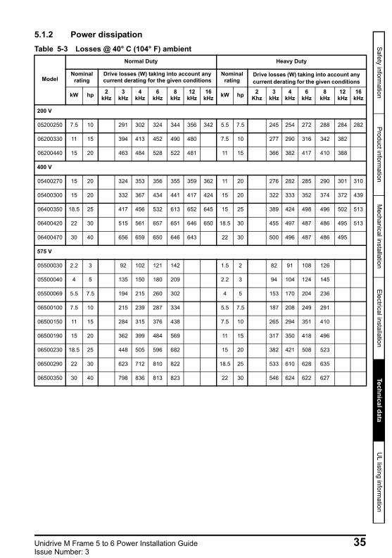
5.1.2 Power dissipationTable 5-3 Losses @ 40° C (104° F) ambient
Model
Normal Duty Heavy Duty
Nominal rating
Drive losses (W) taking into account any current derating for the given conditions
Nominal rating
Drive losses (W) taking into account any current derating for the given conditions
kW hp 2 kHz
3 kHz
4 kHz
6 kHz
8 kHz
12 kHz
16 kHz kW hp 2
Khz3
kHz 4
kHz 6
kHz 8
kHz 12
kHz 16
kHz
200 V
05200250 7.5 10 291 302 324 344 356 342 5.5 7.5 245 254 272 288 284 282
06200330 11 15 394 413 452 490 480 7.5 10 277 290 316 342 382
06200440 15 20 463 484 528 522 481 11 15 366 382 417 410 388
400 V
05400270 15 20 324 353 356 355 359 362 11 20 276 282 285 290 301 310
05400300 15 20 332 367 434 441 417 424 15 20 322 333 352 374 372 439
06400350 18.5 25 417 456 532 613 652 645 15 25 389 424 498 496 502 513
06400420 22 30 515 561 657 651 646 650 18.5 30 455 497 487 486 495 513
06400470 30 40 656 659 650 646 643 22 30 500 496 487 486 495
575 V
05500030 2.2 3 92 102 121 142 1.5 2 82 91 108 126
05500040 4 5 135 150 180 209 2.2 3 94 104 124 145
05500069 5.5 7.5 194 215 260 302 4 5 153 170 204 236
06500100 7.5 10 215 239 287 334 5.5 7.5 187 208 249 291
06500150 11 15 284 315 376 438 7.5 10 265 294 351 410
06500190 15 20 362 399 484 569 11 15 317 350 418 496
06500230 18.5 25 448 505 596 682 15 20 382 421 508 523
06500290 22 30 623 712 810 822 18.5 25 533 610 628 635
06500350 30 40 798 836 813 823 22 30 546 624 622 627
Unidrive M Frame 5 to 6 Power Installation Guide 35Issue Number: 3
Unidrive M frame 5 and 6 Installation Guide issue2.book Page 36 Monday, February 2, 2015 10:29 AM
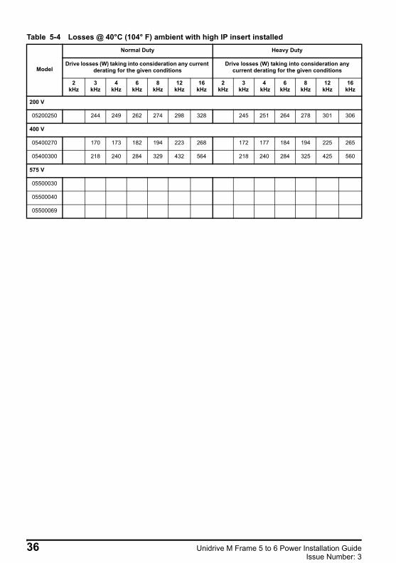
Table 5-4 Losses @ 40°C (104° F) ambient with high IP insert installed
Model
Normal Duty Heavy Duty
Drive losses (W) taking into consideration any current derating for the given conditions
Drive losses (W) taking into consideration any current derating for the given conditions
2 kHz
3 kHz
4 kHz
6 kHz
8 kHz
12 kHz
16 kHz
2 kHz
3 kHz
4 kHz
6 kHz
8 kHz
12 kHz
16 kHz
200 V
05200250 244 249 262 274 298 328 245 251 264 278 301 306
400 V
05400270 170 173 182 194 223 268 172 177 184 194 225 265
05400300 218 240 284 329 432 564 218 240 284 325 425 560
575 V
05500030
05500040
05500069
36 Unidrive M Frame 5 to 6 Power Installation GuideIssue Number: 3
Safety information
Product information
Mechanical installation
Electrical installationTechnical data
UL listing inform
ation
Unidrive M frame 5 and 6 Installation Guide issue2.book Page 37 Monday, February 2, 2015 10:29 AM
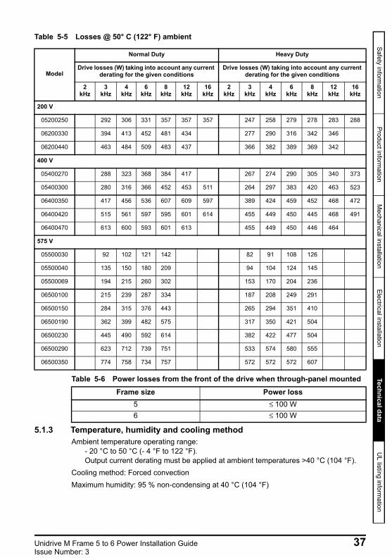
Table 5-5 Losses @ 50° C (122° F) ambient
Table 5-6 Power losses from the front of the drive when through-panel mounted
5.1.3 Temperature, humidity and cooling methodAmbient temperature operating range:
- 20 °C to 50 °C (- 4 °F to 122 °F). Output current derating must be applied at ambient temperatures >40 °C (104 °F).
Cooling method: Forced convectionMaximum humidity: 95 % non-condensing at 40 °C (104 °F)
Model
Normal Duty Heavy Duty
Drive losses (W) taking into account any current derating for the given conditions
Drive losses (W) taking into account any current derating for the given conditions
2 kHz
3 kHz
4 kHz
6 kHz
8 kHz
12 kHz
16 kHz
2 kHz
3 kHz
4 kHz
6 kHz
8 kHz
12 kHz
16 kHz
200 V
05200250 292 306 331 357 357 357 247 258 279 278 283 288
06200330 394 413 452 481 434 277 290 316 342 346
06200440 463 484 509 483 437 366 382 389 369 342
400 V
05400270 288 323 368 384 417 267 274 290 305 340 373
05400300 280 316 366 452 453 511 264 297 383 420 463 523
06400350 417 456 536 607 609 597 389 424 459 452 468 472
06400420 515 561 597 595 601 614 455 449 450 445 468 491
06400470 613 600 593 601 613 455 449 450 446 464
575 V
05500030 92 102 121 142 82 91 108 126
05500040 135 150 180 209 94 104 124 145
05500069 194 215 260 302 153 170 204 236
06500100 215 239 287 334 187 208 249 291
06500150 284 315 376 443 265 294 351 410
06500190 362 399 482 575 317 350 421 504
06500230 445 490 592 614 382 422 477 504
06500290 623 712 739 751 533 574 580 555
06500350 774 758 734 757 572 572 572 607
Frame size Power loss5 ≤ 100 W6 ≤ 100 W
Unidrive M Frame 5 to 6 Power Installation Guide 37Issue Number: 3
Unidrive M frame 5 and 6 Installation Guide issue2.book Page 38 Monday, February 2, 2015 10:29 AM
5.1.4 Storage-40 °C (-40 °F) to +55 °C (122 °F) for long term storage, or to +70 °C (158 °F) for short term storage.Storage time is 2 years. Electrolytic capacitors in any electronic product have a storage period after which they require reforming or replacing. The DC bus capacitors have a storage period of 10 years.The low voltage capacitors on the control supplies typically have a storage period of 2 years and are thus the limiting factor.Low voltage capacitors cannot be reformed due to their location in the circuit and thus may require replacing if the drive is stored for a period of 2 years or greater without power being applied.It is therefore recommended that drives are powered up for a minimum of 1 hour after every 2 years of storage. This process allows the drive to be stored for a further 2 years.
5.1.5 AltitudeAltitude range: 0 to 3,000 m (9,900 ft), subject to the following conditions:
1,000 m to 3,000 m (3,300 ft to 9,900 ft) above sea level: de-rate the maximum output current from the specified figure by 1% per 100 m (330 ft) above 1,000 m (3,300 ft)
For example at 3,000 m (9,900 ft) the output current of the drive would have to be de-rated by 20 %.
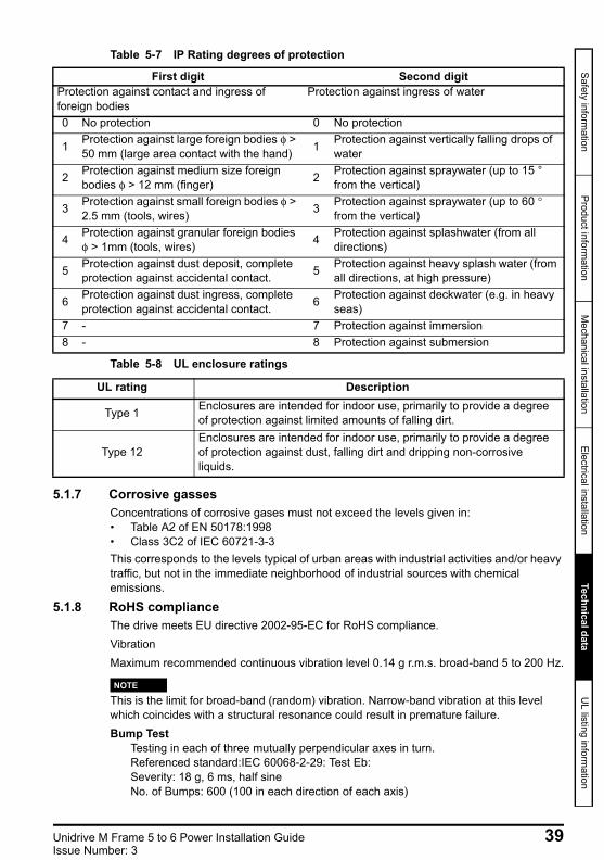
5.1.6 IP / UL RatingThe drive is rated to IP20 pollution degree 2 (dry, non-conductive contamination only) (NEMA 1). However, it is possible to configure the drive to achieve IP65 rating (NEMA 12) at the rear of the heatsink for through-panel mounting (some current derating is required).In order to achieve the high IP rating at the rear of the heatsink with drive size 5 it is necessary to seal a heatsink vent by installing the high IP insert. The IP rating of a product is a measure of protection against ingress and contact to foreign bodies and water. It is stated as IP XX, where the two digits (XX) indicate the degree of protection provided as shown in Table 5-7
38 Unidrive M Frame 5 to 6 Power Installation GuideIssue Number: 3
Safety information
Product information
Mechanical installation
Electrical installationTechnical data
UL listing inform
ation
Unidrive M frame 5 and 6 Installation Guide issue2.book Page 39 Monday, February 2, 2015 10:29 AM
Table 5-7 IP Rating degrees of protection
Table 5-8 UL enclosure ratings
5.1.7 Corrosive gassesConcentrations of corrosive gases must not exceed the levels given in:• Table A2 of EN 50178:1998• Class 3C2 of IEC 60721-3-3This corresponds to the levels typical of urban areas with industrial activities and/or heavy traffic, but not in the immediate neighborhood of industrial sources with chemical emissions.
5.1.8 RoHS complianceThe drive meets EU directive 2002-95-EC for RoHS compliance.VibrationMaximum recommended continuous vibration level 0.14 g r.m.s. broad-band 5 to 200 Hz.
This is the limit for broad-band (random) vibration. Narrow-band vibration at this level which coincides with a structural resonance could result in premature failure.Bump Test
Testing in each of three mutually perpendicular axes in turn.Referenced standard:IEC 60068-2-29: Test Eb:Severity: 18 g, 6 ms, half sineNo. of Bumps: 600 (100 in each direction of each axis)
First digit Second digitProtection against contact and ingress of foreign bodies
Protection against ingress of water
0 No protection 0 No protection
1 Protection against large foreign bodies φ > 50 mm (large area contact with the hand) 1 Protection against vertically falling drops of
water
2 Protection against medium size foreign bodies φ > 12 mm (finger) 2 Protection against spraywater (up to 15 °
from the vertical)
3 Protection against small foreign bodies φ > 2.5 mm (tools, wires) 3 Protection against spraywater (up to 60 °
from the vertical)
4 Protection against granular foreign bodies φ > 1mm (tools, wires) 4 Protection against splashwater (from all
directions)
5 Protection against dust deposit, complete protection against accidental contact. 5 Protection against heavy splash water (from
all directions, at high pressure)
6 Protection against dust ingress, complete protection against accidental contact. 6 Protection against deckwater (e.g. in heavy
seas)7 - 7 Protection against immersion8 - 8 Protection against submersion
UL rating Description
Type 1 Enclosures are intended for indoor use, primarily to provide a degree of protection against limited amounts of falling dirt.
Type 12Enclosures are intended for indoor use, primarily to provide a degree of protection against dust, falling dirt and dripping non-corrosive liquids.
NOTE
Unidrive M Frame 5 to 6 Power Installation Guide 39Issue Number: 3
Unidrive M frame 5 and 6 Installation Guide issue2.book Page 40 Monday, February 2, 2015 10:29 AM
Random Vibration Test Testing in each of three mutually perpendicular axes in turn.Referenced standard:IEC 60068-2-64: Test Fh:Severity: 1.0 m²/s³ (0.01 g²/Hz) ASD from 5 to 20 Hz
-3 dB/octave from 20 to 200 HzDuration: 30 minutes in each of 3 mutually perpendicular axes.
Sinusoidal Vibration Test Testing in each of three mutually perpendicular axes in turn.Referenced standard: IEC 60068-2-6: Test Fc:Frequency range: 5 to 500 HzSeverity: 3.5 mm peak displacement from 5 to 9 Hz
10 m/s² peak acceleration from 9 to 200 Hz 15 m/s² peak acceleration from 200 to 500 Hz
Sweep rate: 1 octave/minuteDuration: 15 minutes in each of 3 mutually perpendicular axes.
EN 61800-5-1:2007, Section 5.2.6.4. referring to IEC 60068-2-6
Frequency range: 10 to 150 HzAmplitude: 10 to 57 Hz at 0.075 mm pk
57 to 150 Hz at 1g pSweep rate: 1 octave/minuteDuration: 10 sweep cycles per axis in each of 3 mutually perpendicular axes
5.1.9 Starts per hourBy electronic control: unlimitedBy interrupting the AC supply: ≤20 (equally spaced)
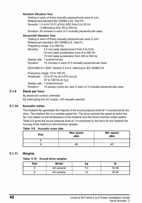
5.1.10 Acoustic noiseThe heatsink fan generates the majority of the sound pressure level at 1 m produced by the drive. The heatsink fan is a variable speed fan. The drive controls the speed at which the fan runs based on the temperature of the heatsink and the drive's thermal model system. Table 5-9 gives the sound pressure level at 1 m produced by the drive for the heatsink fan running at the maximum and minimum speeds.Table 5-9 Acoustic noise data
5.1.11 WeightsTable 5-10 Overall drive weights
Size Max speeddBA
Min speeddBA
56 48 40
Size Model kg lb5 All variants 7.4 16.306 All variants 14 30.90
40 Unidrive M Frame 5 to 6 Power Installation GuideIssue Number: 3
Safety information
Product information
Mechanical installation
Electrical installationTechnical data
UL listing inform
ation
Unidrive M frame 5 and 6 Installation Guide issue2.book Page 41 Monday, February 2, 2015 10:29 AM
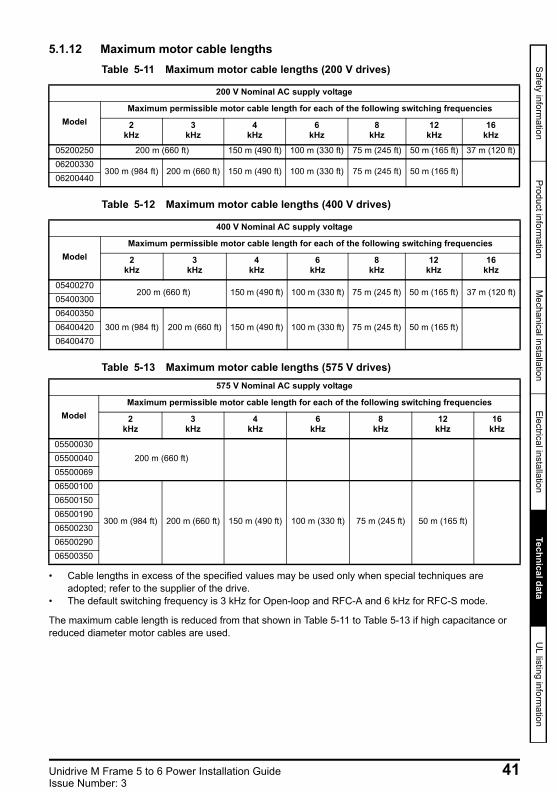
5.1.12 Maximum motor cable lengthsTable 5-11 Maximum motor cable lengths (200 V drives)
Table 5-12 Maximum motor cable lengths (400 V drives)
Table 5-13 Maximum motor cable lengths (575 V drives)
• Cable lengths in excess of the specified values may be used only when special techniques are adopted; refer to the supplier of the drive.
• The default switching frequency is 3 kHz for Open-loop and RFC-A and 6 kHz for RFC-S mode.
The maximum cable length is reduced from that shown in Table 5-11 to Table 5-13 if high capacitance or reduced diameter motor cables are used.
200 V Nominal AC supply voltage
ModelMaximum permissible motor cable length for each of the following switching frequencies
2 kHz
3 kHz
4 kHz
6 kHz
8 kHz
12 kHz
16 kHz
05200250 200 m (660 ft) 150 m (490 ft) 100 m (330 ft) 75 m (245 ft) 50 m (165 ft) 37 m (120 ft)06200330
300 m (984 ft) 200 m (660 ft) 150 m (490 ft) 100 m (330 ft) 75 m (245 ft) 50 m (165 ft)06200440
400 V Nominal AC supply voltage
ModelMaximum permissible motor cable length for each of the following switching frequencies
2kHz
3kHz
4kHz
6kHz
8kHz
12kHz
16kHz
05400270200 m (660 ft) 150 m (490 ft) 100 m (330 ft) 75 m (245 ft) 50 m (165 ft) 37 m (120 ft)
0540030006400350
300 m (984 ft) 200 m (660 ft) 150 m (490 ft) 100 m (330 ft) 75 m (245 ft) 50 m (165 ft)0640042006400470
575 V Nominal AC supply voltage
ModelMaximum permissible motor cable length for each of the following switching frequencies
2kHz
3kHz
4kHz
6kHz
8kHz
12kHz
16kHz
05500030200 m (660 ft)05500040
0550006906500100
300 m (984 ft) 200 m (660 ft) 150 m (490 ft) 100 m (330 ft) 75 m (245 ft) 50 m (165 ft)
0650015006500190065002300650029006500350
Unidrive M Frame 5 to 6 Power Installation Guide 41Issue Number: 3
Unidrive M frame 5 and 6 Installation Guide issue2.book Page 42 Monday, February 2, 2015 10:29 AM
6 UL listing information6.1 General6.1.1 Scope of approvals
All models are listed to both US and Canadian safety requirements.The UL file number is: E171230.The Manufacturing Location Code is: 8D14.
6.1.2 Manufacturers nameThe manufacturer is Control Techniques Ltd
6.1.3 Electrical ratingsThe electrical ratings are tabulated in the Drive User Guide.
6.1.4 Multiple wiring arrangementsThe drives are not intended for use in applications that require different wiring arrangements. The drives are not multiple rated.
6.1.5 Model numbersModel numbers are shown in the Drive User Guide.
6.1.6 Plenum ratingThe drives are suitable for installation in a compartment (duct) handling conditioned air when installed as enclosed types with the intended Type 1 terminal kit.
6.1.7 Operating temperatureThe drives are rated for use at 40 °C ambient temperature.Operation at 50 °C is permitted with derated output. Refer to the Drive User Guide for further information.
6.1.8 Installation warnings, cautions and notesThe appropriate installation warnings, cautions and notes are located in Chapter 1 Safety information on page 8.
6.2 Overload, overcurrent and overspeed protection6.2.1 Degree of protection level
The devices incorporate solid state overload protection for the motor load. The protection levels are expressed as a percentage of full-load current. Refer to the Drive User Guide for further information.In order for the motor protection to work properly, the motor rated current must be entered into Pr 00.046 or Pr 05.007.The protection level may be adjusted below 150 % if required. Refer to the Drive User Guide for further information.The drive incorporates solid state motor overspeed protection. However, this feature does not provide the level of protection provided by an independent, high-integrity overspeed protection device.
42 Unidrive M Frame 5 to 6 Power Installation GuideIssue Number: 3
Safety information
Product information
Mechanical installation
Electrical installationTechnical data
UL listing inform
ation
Unidrive M frame 5 and 6 Installation Guide issue2.book Page 43 Monday, February 2, 2015 10:29 AM
6.2.2 Thermal memory protection The drives are provided with motor load and speed sensitive overload protection with thermal memory retention. The thermal memory protection complies with UL requirements for shutdown, loss of power and speed sensitivity.For a full explanation of the thermal protection system refer to the Drive User Guide. In order to comply with UL requirements for thermal memory retention it is necessary to set the Thermal Protection Mode (Pr 04.016) to zero; and the Low Speed Protection Mode (Pr 04.025) must be set to 1.
6.2.3 Use with motors with thermal protectors The drive is provided with a means to accept and act upon a signal from a thermal sensor or switch imbedded in the motor or from an external protective relay. Refer to the Drive User Guide for further information.
6.2.4 Specific overcurrent protective device The drive is not required to be connected to a supply source with a specific overcurrent protective device other than those specified in section 2.3 Ratings on page 12.
6.3 Short-circuit protection for branch circuits6.3.1 Short-circuit rating
The drive is suitable for use on a circuit capable of delivering not more than 100,000 RMS symmetrical amperes, 600 Vac maximum, when protected by the overcurrent protective devices as described in section 2.3 Ratings on page 12.Unless otherwise indicated in the Drive User Guide, branch fuses may be any UL listed class CC, J or T rated 600 Vac.Unless otherwise indicated in section 2.3 Ratings on page 12, circuit breakers may be any UL listed type with category control number DIVQ or DIVQ7, rated 600 Vac.
6.3.2 Solid state short-circuit protection The drive is provided with solid state short-circuit protection. Integral solid state protection does not provide branch circuit protection. Branch circuit protection must be provided in accordance with the National Electrical Code and any additional local codes.
6.3.3 Short-circuit protection for branch circuits (group installation) Frame sizes 5 and 6 are approved for motor group installation on a circuit capable of delivering not more than 100,000 RMS symmetrical amperes, 600 V max, when protected by class CC, J, T or HSJ fuses.
6.3.4 Common DC bus systems Frame sizes 5 and 6 are approved for use in modular drive systems using a common DC bus.For permitted combinations of converter and inverter, along with the required branch circuit protection, contact Control Techniques.
6.4 Control circuit protection6.4.1 Control circuit wiring
All control circuits are located in limited voltage, limited current isolated secondary circuits. Additional wiring protection is not required.
Unidrive M Frame 5 to 6 Power Installation Guide 43Issue Number: 3
Unidrive M frame 5 and 6 Installation Guide issue2.book Page 44 Monday, February 2, 2015 10:29 AM
6.4.2 Supplemental fuse When the control circuits are supplied with an external 24 V supply, a supplemental fuse is required as described in the Drive User Guide.
6.4.3 Accessory kit boxesAll drives are supplied with an accessory kit box, refer to the Drive User Guide.
6.5 Wiring terminal markings6.5.1 Marking for proper connection
All main terminals are plainly marked. There are no multiple circuit arrangements.
6.5.2 Terminal connection of ground supply conductor. The terminals for the connection of the grounded supply circuit conductor are identified by means of an earth symbol (IEC 60417, symbol No. 5019).Ground connections must use UL listed closed loop (ring) terminals.
6.5.3 User relay contact An isolated user relay contact is provided that may be wired in the field to become part of a class 1 or class 2 circuit. This is described in the Drive User Guide.
6.5.4 Type of conductorsUse copper conductors only.
6.5.5 Temperature rating of conductors Use 75 °C rated conductors only.
6.5.6 Cable sizes for group installation Frame sizes 5 and 6 are approved for motor group installation with input and output cable sizes restricted to 125 % of rated current.
6.5.7 Torque valuesTorque values for field wiring terminals are provided in section 3.8 Terminal size and torque settings on page 20.
6.6 Environment6.6.1 Environment
Drives are intended for operation in pollution degree 2 environments.Drives are supplied as open type.Drives are classed as Enclosed Type 1 when installed with the intended Type 1 terminal kit.Drives are classed as Type 12 when installed in a Type 12 enclosure.
6.7 Mounting6.7.1 Surface mounting
All drives are suitable for Surface mounting. Mounting instructions are given in the Drive User Guide.
6.7.2 Bookcase mounting In order to minimize the width of the installation, drives may be mounted side by side with or without airspace between them.
44 Unidrive M Frame 5 to 6 Power Installation GuideIssue Number: 3
Safety information
Product information
Mechanical installation
Electrical installationTechnical data
UL listing inform
ation
Unidrive M frame 5 and 6 Installation Guide issue2.book Page 45 Monday, February 2, 2015 10:29 AM
6.7.3 Tile mountingFrame size 5 drive is suitable for tile mounting. The drive is mounted sideways with the side panel against the mounting surface. Tile mounting kits are available.
6.7.4 Through-hole mounting All models may be through-hole mounted. When through-hole mounted, inside a Type 12 enclosure, the high-IP insert (where provided) and the Type 12 sealing kit must be used in order to prevent ingress of dust and water. Refer to the Drive User Guide for further information.
6.8 Listed accessories6.8.1 Option modules
The following option modules and accessories are UL listed:Open Type:
Type 1/ Type 12:Remote Keypad.
SI-PROFINET RT SI-Universal EncoderSI-EtherCAT SI-Applications PlusSI-Ethernet MCi200SI-DeviceNet MCi210SI-CANopen SD-Card AdaptorSI-PROFIBUS KI-485 AdaptorSI-Safety KI-KeypadSI-I/O KI-Keypad RTCSI-Encoder
Not all option modules are compatible with all drive models.NOTE
Unidrive M Frame 5 to 6 Power Installation Guide 45Issue Number: 3

0478-0255-03
Unidrive M frame 5 and 6 Installation Guide issue2.book Page 46 Monday, February 2, 2015 10:29 AM