Embed Size (px)
Citation preview

8/8/2019 Power Plant Acoustics-b
http://slidepdf.com/reader/full/power-plant-acoustics-b 1/96
UFC 3-450-0215 May 2003
UNIFIED FACILITIES CRITERIA (UFC)
POWER PLANT ACOUSTICS
APPROVED FOR PUBLIC RELEASE; DISTRIBUTION UNLIMITED
8/8/2019 Power Plant Acoustics-b
http://slidepdf.com/reader/full/power-plant-acoustics-b 2/96
UFC 3-450-0215 May 2003
1
UNIFIED FACILITIES CRITERIA (UFC)
POWER PLANT ACOUSTICS
Any copyrighted material included in this UFC is identified at its point of use.Use of the copyrighted material apart from this UFC must have the permission of thecopyright holder.
U.S. ARMY CORPS OF ENGINEERS (Preparing Activity)
NAVAL FACILITIES ENGINEERING COMMAND
AIR FORCE CIVIL ENGINEER SUPPORT AGENCY
Record of Changes (changes are indicated by \ 1 \ ... / 1 /)
Change No. Date Location
This UFC supersedes TM 5-805-9, dated 30 December 1983. The format of this UFC does notconform to UFC 1-300-01; however, the format will be adjusted to conform at the next revision.The body of this UFC is a document of a different number.

8/8/2019 Power Plant Acoustics-b
http://slidepdf.com/reader/full/power-plant-acoustics-b 3/96
ARMY TM 5-805-9
AIR FORCE AFM 88-20
NAVY NAVFAC DM-3.14
POWER PLANT ACOUSTICS
DEPARTMENTS OF THE ARMY, THE AIR FORCE, AND THE NAVY
DECEMBER 1983

8/8/2019 Power Plant Acoustics-b
http://slidepdf.com/reader/full/power-plant-acoustics-b 4/96

8/8/2019 Power Plant Acoustics-b
http://slidepdf.com/reader/full/power-plant-acoustics-b 5/96
POWER PLANT ACOUSTICS
TABLE OF CONTENTS
Paragraph
C H A P T E R 1 . SCOPE OF MANUAL
Purpose and scope . . . . . . . . . . . . . . . . . . . . . . . . . . . . . . . . . . . . . . . . . . . . . . . . . . . . . . . . . . . . . . . . . . . . . . . 1–1
General contents . . . . . . . . . . . . . . . . . . . . . . . . . . . . . . . . . . . . . . . . . . . . . . . . . . . . . . . . . . . . . . . . . . . . . . . . . 1–2
Typical problems of uncontrolled noise . . . . . . . . . . . . . . . . . . . . . . . . . . . . . . . . . . . . . . . . . . . . . . . . . . . . . 1–3
Cross-referenc e . . . . . . . . . . . . . . . . . . . . . . . . . . . . . . . . . . . . . . . . . . . . . . . . . . . . . . . . . . . . . . . . . . . . . . . . . 1–4
2. SOUND ANALYSIS PROCEDURE
Contents of chapter . . . . . . . . . . . . . . . . . . . . . . . . . . . . . . . . . . . . . . . . . . . . . . . . . . . . . . . . . . . . . . . . . . . . . . 2–1
General procedure . . . . . . . . . . . . . . . . . . . . . . . . . . . . . . . . . . . . . . . . . . . . . . . . . . . . . . . . . . . . . . . . . . . . . . . . 2-2
Sound level criteria . . . . . . . . . . . . . . . . . . . . . . . . . . . . . . . . . . . . . . . . . . . . . . . . . . . . . . . . . . . . . . . . . . . . . . . 2–3Vibration criteria . . . . . . . . . . . . . . . . . . . . . . . . . . . . . . . . . . . . . . . . . . . . . . . . . . . . . . . . . . . . . . . . . . . . . . . . 2–4Indoor sound distribution . . . . . . . . . . . . . . . . . . . . . . . . . . . . . . . . . . . . . . . . . . . . . . . . . . . . . . . . . . . . . . . . . 2–5
Outdoor sound propagation . . . . . . . . . . . . . . . . . . . . . . . . . . . . . . . . . . . . . . . . . . . . . . . . . . . . . . . . . . . . . . . . 2–6Reciprocating engine noise data . . . . . . . . . . . . . . . . . . . . . . . . . . . . . . . . . . . . . . . . . . . . . . . . . . . . . . . . . . .2–7
Gas turbine engine noise data. . . . . . . . . . . . . . . . . . . . . . . . . . . . . . . . . . . . . . . . . . . . . . . . . . . . . . . . . . . . . 2–8
Data forms . . . . . . . . . . . . . . . . . . . . . . . . . . . . . . . . . . . . . . . . . . . . . . . . . . . . . . . . . . . . . . . . . . . . . . . . . . . . . . 2-9
Other noise sources . . . . . . . . . . . . . . . . . . . . . . . . . . . . . . . . . . . . . . . . . . . . . . . . . . . . . . . . . . . . . . . . . . . . . . 2-10
3. NOISE AND VIBRATION CONTROL FOR ENGINE INSTALLATIONS
Engine noise control . . . . . . . . . . . . . . . . . . . . . . . . . . . . . . . . . . . . . . . . . . . . . . . . . . . . . . . . . . . . . . . . . . . . . . 3–1
Noise escape through an outdoor wall . . . . . . . . . . . . . . . . . . . . . . . . . . . . . . . . . . . . . . . . . . . . . . . . . . . . . . 3–2
Reactive mufflers for reciprocating engines . . . . . . . . . . . . . . . . . . . . . . . . . . . . . . . . . . . . . . . . . . . . . . . . . 3–3
Dissipative mufflers . . . . . . . . . . . . . . . . . . . . . . . . . . . . . . ,. . . . . . . . . . . . . . . . . . . . . . . . . . . . . . . . . . . . . . . 3-4
Ventilation duct lining . . . . . . . . . . . . . . . . . . . . . . . . . . . . . . . . . . . . . . . . . . . . . . . . . . . . . . . . . . . . . . . . . . . . 3–5
Vibration isolation of reciprocating engines . . . . . . . . . . . . . . . . . . . . . . . . . . . . . . . . . . . . . . . . . . . . . . . . . 3–6
Vibration isolation of turbine engines . . . . . . . . . . . . . . . . . . . . . . . . . . . . . . . . . . . . . . . . . . . . . . . . . . . . . . 3-7Vibration isolation of auxiliary equipment . . . . . . . . . . . . . . . . . . . . . . . . . . . . . . . . . . . . . . . . . . . . . . . . . . . 3-8
Use of hearing protection devices . . . . . . . . . . . . . . . . . . . . . . . . . . . . . . . . . . . . . . . . . . . . . . . . . . . . . . . . . . 3-9Nondisturbing warning and paging systems . . . . . . . . . . . . . . . . . . . . . . . . . . . . . . . . . . . . . . . . . . . . . . . . . 3-10
Quality of analysis procedure . . . . . . . . . . . . . . . . . . . . . . . . . . . . . . . . . . . . . . . . . . . . . . . . . . . . . . . . . . . . . . 3-11
4. EXAMPLES OF SOUND ANALYSIS PROCEDURE
Summary of examples . . . . . . . . . . . . . . . . . . . . . . . . . . . . . . . . . . . . . . . . . . . . . . . . . . . . . . . . . . . . . . . . . . . . 4–1
Example of an on-grade gas or diesel engine installation . . . . . . . . . . . . . . . . . . . . . . . . . . . . . . . . . . . . . 4–2
Example of an on-grade packaged gas turbine generator plant.... . . . . . . . . . . . . . . . . . . . . . . . . . . . . 4–3
Summary and conclusions . . . . . . . . . . . . . . . . . . . . . . . . . . . . . . . . . . . . . . . . . . . . . . . . . . . . . . . . . . . . . . . . . 4–4
A PPENDIX A. DATA FORMS . . . . . . . . . . . . . . . . . . . . . . . . . . . . . . . . . . . . . . . . . . . . . . . . . . . . . . . . . . . . . . . . . . . . . . . . . . A-1
B. REFERENCES . . . . . . . . . . . . . . . . . . . . . . . . . . . . . . . . . . . . . . . . . . . . . . . . . . . . . . . . . . . . . . . . . . . . . . . . . B-1
c. BIBLIOGRAPHY . . . . . . . . . . . . . . . . . . . . . . . . . . . . . . . . . . . . . . . . . . . . . . . . . . . . . . . . . . . . . . . . . . . . . . . . C-1
Page
1-1
1-1
1-1
1-2
2-1
2-1
2-22-2
2-2
2-3
2-32-8
2–13
2-13
3-1
3-2
3-3
3-4
3-12
3-12
3-153-15
3-153-16
3-16
4-1
4-14-43
4-52
i

8/8/2019 Power Plant Acoustics-b
http://slidepdf.com/reader/full/power-plant-acoustics-b 6/96
ii
8/8/2019 Power Plant Acoustics-b
http://slidepdf.com/reader/full/power-plant-acoustics-b 7/96
. . .
Ill

8/8/2019 Power Plant Acoustics-b
http://slidepdf.com/reader/full/power-plant-acoustics-b 8/96
CHAPTER 1
SCOPE OF MANUAL
1-1. Purpose and sc ope.
This manual provides noise control data and analy-
sis procedures for design and construction of die-
sel, gas, and gas turbine engine facilities at mili-
tary installations in the continental United States
(CONUS) and for U.S. military facilities around
the world. The data and procedures are directed
primarily toward the control of noise from engine-
driven electric generators but are equally appro-
priate for any power system using reciprocating or
tu rbine’ engines. This manual applies to all new
construction and to major alterations of existing
structures. U.S. military facilities that requirehigher standards because of special functions or
missions are not covered in this manual; criteria
and standards for these exceptions are normally
contained in design directives for the particular fa-
cilities. If procedures given in this manual do not
provide all the functional and structural needs of a
project, recognized construction practices and de-
sign standards can be used.
1-2. General contents.
This manual presents a review of applicable sound-
and vibration-level criteria, sound level data for
reciprocating- and turbine-type engines driven by
gas and liquid fuels, a basic approach for evaluating
an engine noise problem, procedures for controlling
engine noise and vibration, and examples that illus-
trate the entire system analysis. The sound level
data quoted in the manual are based on measure-
ments of more than 50 diesel and natural gas
reciprocating engines and more than 50 gas turbine
engines. Almost all of the leading man ufactur ers
are represented in the collection of data. The sound
level data given in the manual are 2 dB higher than
the average of the measured sound levels in order
to include engines that are slightly noisier than theaverage. This inclusion means that designs based
on the data and methods used in the manual will
provide design ‘pr otection for a ppr oxima tely 80 to
90 percent of all engines in any random selection.
The few remaining engines may have sound levels
of possibly 1 to 5 dB above the values used here.
Sound power level data are quoted for the engines,
but the procedures in the manual show how these
data are converted to the sound pressure levels
that are needed. The term “engine,” as used in themanual, may be construed to represent “engine-
generator” or “engine-generator set” when used in
the larger sense to include both the driver and the
driven equipment.
1-3. Typical problems of unc ontrol led noise.
The noise of a typical engine-driven electric gener-
ator is great enough that it can cause some loss of
hearing to personnel working in the same room
with the engine, and the noise radiated outdoors by
an unenclosed engine can be heard a mile away and
can disturb the sleep of people living a half-mileaway—if adequate noise control measures are not
taken. These two extremes show the range of the
problems that may be encountered with a power
plant, and they illustrate the range of noise prob-
lems covered by this manual. A few specific exam-
ples are listed and discussed briefly.
a. Hearing damage to engine operator. H u m a n
hearing loss represents the most serious aspect of
the engine noise problem. A power plant operator
who regularly spends 8 hours per day inside an en-
gine room, with no acoustic enclosure and no ear
protection, will experience some degree of noise-
induced permanent hearing loss over a period of time in that noise field. Military regulations pro-
hibit such noise exposures, and this manual recom-
mends separate control rooms for such problems.
b. Speech interference. Most of the “intelligibili-
ty” of the voice is contained in the middle and up-
per frequencies of the total audio range of hearing.
When an interfering noise has a frequency spread
that covers the middle and upper portion of the to-
tal audio range, it has the potential of “masking”
the speech sounds. If the interfering noise is not
very loud, a talker overcomes the masking effect
by talking louder. If the interfering noise is veryloud, the talker must shout and the listener must
move closer to hear and understand the spoken
message. If the interfering noise is too loud, the
voice is not strong enough to overcome the mask-
ing effect— even at short distances while the
speaker is shouting almost into the listener ’s ear.
In such high noise levels, speech communication
becomes difficult, tiring, and frustrating, and facts
may be distorted when the listener erroneously in-
1-1

8/8/2019 Power Plant Acoustics-b
http://slidepdf.com/reader/full/power-plant-acoustics-b 9/96
TM5-805-9/AFM 88-20/NAVFAC DM-3.14
terprets the imperfectly heard speech. Long sen-
tences are fatiguing to the talker, and long or unfa-
miliar words are not understood by the listener.
Engine room noise usually discourages long sen-
tences, unfamiliar terms, and complex conversa-
t ions . Quie te r sur roundings a re requ i red fo r
lengthy, precise speech communication. The manu-
al addresses this problem.
c. Interference with warning signals. In somenoisy work areas, warning bells or horns and an-
nouncement or call systems are turned up to such
high levels that they are startling when they come
“on” abruptly. In fact, because they must pene-
trate into all areas of a noisy plant, they are so loud
they “hurt” the ear when a listener happens to be
near the signal source. On the other hand, a
“weak” bell or call might not be heard at all. Some
auxiliary paging and warning systems are sug-
gested later in the manual.
d. Difficulty of telephone usage. The noise lev-
els inside most engine rooms completely precludetelephone usage. For emergency use as well as for
routine matters, a quiet space satisfactory for reli-
able telephone usage must be provided within or
immediately adjoining an engine room. The acous-
tical requirements for such a space are covered in
the manual .
e. Noise intrusion into nearby work spaces. Dif-
ferent types of work spaces require different types
of acoustical environments. The maintenance shop
beside a diesel engine room can tolerate a higher
background noise than the offices and meeting
rooms of the main headquarters of a base. It is pos-
sible to categorize various typical work areas ac-
cording to the amount of background noise consid-
ered acceptable or desirable for those areas. A
schedule of “noise criteria” provides a range of
noise levels considered appropriate for a range of
typical work spaces, and the design portion of the
manual indicates the methods of achieving these
noise criteria, relative to engine-produced noise.
Engine noise is accepted as a necessary part of the
power plant, but this noise is unwanted almost ev-
erywhere outside the engine room—hence, the em-
phasis on adequate noise reduction through archi-
tectural and engineering design to bring this noise
down to an innocuous, unintruding “background” in
those areas requir ing control led degrees of
quietness.
f. Community noise problems. Rest, relaxation,
and sleep place severe requirements on the noise
control problem. Whether the base barracks or on-
site housing or slightly hostile off-base neighbors
control the design, the need for relatively quiet
surroundings is recognized. The noise criteria and
acoustic designs provided by the manual are aimed
at achieving the background noise levels that will
permit rest, relaxation, and sleep in nearby hous-
ing or residential areas.
g. Summary. These illustrations encompass thegoals of this manual. In varying degrees, any noise
problem encountered will involve hearing preser-
vation, speech communication, annoyance, or noise
intrusion. To a high degree, such problems can be
evaluated quantitatively; practical and successful
solutions can be worked out with the aid of the
guidelines and recommendations presented in the
manual .
1-4. Cross reference.
The manual “Noise and Vibration Control for Me-
chanical Equipment” (TM 5-805-4/AFM 88-37/
NAVFAC DM-3.10), hereinafter called the “N&V”
manual, is a complemental reference incorporating
many of the basic data and details used extensively
in this manual. (See app. B for additional refer-
ences and app. C for related publications. )
1-2

8/8/2019 Power Plant Acoustics-b
http://slidepdf.com/reader/full/power-plant-acoustics-b 10/96
TM 5–805-9/AFM 88–201NAVFAC DM–3.14
CHAPTER 2
SOUND ANA LYSIS PROCEDURE
2-1. Contents of chapter.
This chapter summarizes the four basic steps for
evaluating and solving an engine noise problem.
The steps involve sound level data for the source,sound (and vibration) criteria for inhabited spaces,
the fundamentals of sound travel (both indoors and
outdoors), and knowledge and use of sound (and vi-
bration) treatments to bring the equipment into
conformance with the criteria conditions applicable
to the work spaces and neighboring areas. Much of
this material is discussed in detail in the N&V
manual, but brief summaries of the key items are
listed and reviewed here. Special noise- and vibra-
tion-control treatments (beyond the normal uses of
walls, structures, and absorption materials to con-
tain and absorb the noise) are discussed in chapter
3, and examples of the analysis procedure are giv-en in chapter 4.
2–2. General procedure.
In its simplest form, there are four basic steps to
evaluating and solving a noise problem. Step 1 re-
quires the estimation or determination of the noise
levels produced by a noise source at the particular
point of interest, on the initial assumption that no
special acoustic treatment is used or required. Step
2 requires the establishment of a noise level crite-
rion considered applicable for the particular pointof interest. Step 3 consists of determining the
amount of “excess noise” or the “required noise re-
duction” for the problem. This reduction is simply
the algebraic difference, in decibels, between the
noise levels produced by the equipment (step 1
above) and the criterion levels desired for the re-
gion of interest (step 2 above). Step 4 involves the
design or selection of the acoustic treatment or the
architectural structure that will provide the “re-
quired noise reduction (step 3 above). This basic
procedure is carried out for each octave frequency
band, for each noise source if there are several
sources, for each noise path if there are severalpossible paths, and for each point of interest that
receives the noise. The basic procedure becomes
complicated because of the multiplicity of all these
factors. The ultimate success of the design depends
largely on devising adequate practical solutions,
but it also requires that a crucial noise source,
path, or receiver has not been overlooked. Addi-
tional details that fall under these four steps follow
immediately.
a. Step 1, source data.
(1) The sound power levels (PWLs) of the en-
gine noise sources are given below in paragraphs
2–7 and 2–8. Sound pressure levels (SPLs) or
sound power levels of some auxiliary sources may
be found in -chapter 7 of the N&V manual, or may
have to be obtained from the literature or from the
equipment manufacturers.
(2) Detailed procedures for converting PWL
data to SPL data and for estimating the SPL of a
source at any receiver position of interest indoors
or outdoors are given in chapters 5 and 6 of the
N&V manual.
(3) Where several noise sources exist, the ac-
cumulated effect must be considered, so simple
procedures are given (Appendix B of the N&V
manual) for adding the contributions of multiplenoise sources by “decibel addition. ”
b. Step Z , criteria.
(1) Applicable criteria are discussed in the
N&V manual (chap. 3 for sound and chap. 4 for vi-
bration) and are summarized in paragraphs 2-3 and
2–4 below for most situations in which an intruding
or interfering noise may influence an acoustic envi-
ronment (hearing damage due to high noise levels,
interference with speech, interference with tele-
phone use and safety or warning signals, and noise
annoyance at work and at home).
(2) In a complex problem, there may be a mul-
tiplicity of criteria as well as a multiplicity of
sources and paths. An ultimate design might have
to incorporate simultaneously a hearing protection
criterion for one operator, reliable speech or tele-
phone communication for another operator, accept-
able office noise levels for other personnel, and ac-
ceptable s leeping condit ions for s t i l l o ther
personnel.
c. Step 3, noise reduction requirements.
(1) The required noise reduct ion is that
amount of noise level that exceeds the applicable
criterion level. Only simple subtraction is involved,
but, again, it is essential that all noise sources beconsidered at each of the var ious cr i ter ion
situations.
(2) Some noise sources are predominantly of
high-frequency content and add l i t t le low-
frequency noise to the problem, while others are
predominant ly low-frequency. Thus, f requency
content by octave bands is important in determin-
ing the portion of excess noise contributed by a
given source.
2-1

8/8/2019 Power Plant Acoustics-b
http://slidepdf.com/reader/full/power-plant-acoustics-b 11/96
d. Step 4, noise control.
(1) Most common methods of controlling indoor
noise by design considerations are set forth in the
N&V manual: the effectiveness (transmission loss)
of walls and structures in containing noise, and the
effectiveness of distance and sound absorption
(Room Constant) in reducing noise levels in the re-
verberant portion of a room. Special noise control
treatments for use with engine installations arediscussed in chapter 3 of this manual; they include
mufflers, lined ducts, vibration isolation, the use of
ear protection devices, and the use of nondisturb-
ing warning or paging systems.
(2) The influence of distance, outdoor barriers
and trees, and the” directivity of large sources are
considered both as available noise control measures
as well as factors in normal outdoor sound propaga-
tion (N&V manual).
2–3. Sound level criteria.
a. Indoor noise criteria. Noise cri ter ion (NC)
and preferred noise criterion (PNC) curves areused to express octave-band sound pressure levels
considered acceptable for a wide range of occupied
spaces. Paragraph 3–2 in the N&V manual dis-
cusses these noise criterion curves, which are di-
rectly applicable here for setting design goals for
noise levels from engine installations. Tables 3–1
and 3–2 of the N&V manual summarize the octive-
band sound pressure levels and the suggested ap-
plications of the NC and PNC curves. Also, in the
N&V manual, paragraph 3–2d and 3–3 relate to
speech interference by noise, and paragraph 3–2e
offers criteria for telephone usage in the presence
of noise.
b. Community noise criteria. A widely used
method for estimating the relative acceptability of
a noise that intrudes into a neighborhood is de-
scribed in paragraph 3–3c of the N&V manual. It is
known as the Composi te Noise Rat ing (CNR)
method, modified over the years to include addi-
tional factors that are found to influence communi-
ty attitudes toward noise. The method is readily
applicable to the noise of engine installations
(whether operating continuously or intermittently)
as heard by community residents (whether on-base
or off-base). Figures 3–3, 3–4, and 3–5 and tables3–4 and 3–5 of the N&V manual provide relatively
simple access to the method. If the analysis shows
that the noise will produce an uncomfortable or
unacceptable community reaction to the noise, the
method shows approximately how much noise re-
duction is required to achieve an acceptable com-
munity response to the noise.
c. Hearing conservation criteria. Paragraph 3–4
of the N&V manual reviews briefly the history of
key studies on the influence of high-level, long-
time noise exposures on hearing damage, leading
up to the Occupational Safety and Health Act
(OSHA) of 1970. The principal noise requirementsof the act are summarized. A sl ight ly more con-
servative and protective attitude toward hearing
conservation is contained in the DoD Instruction
6055.3. This document is summarized in paragraph
3–4d of the N&V manual. In brief, this document
defines an exposure in excess of 84 dB(A) for 8
hours in any 24-hour period as hazardous and pro-
vides a formula for calculating the time limit of safe
exposure to any A-weighted sound level (equation
3–4 and table 3–9 of the N&V manual). Other parts
of DoD Instruction 6055.3 refer to impulsive noise,
noise-hazardous areas, labeling of noise-hazardous
tools and areas, issuance and use of hearings pro-
tection devices, educational programs on the ef-
fects of noise, audiometric testing programs, and
the importance of engineering noise control for pro-
tecting personnel. from noise.d. Application of criteria to power plant noise.
Each of the above three criteria evaluations should
be applied to plants with engine installations, and
the total design of each plant or engine installation
should contain features or noise control treatments
aimed at achieving acceptable noise levels for
nearby offices and work spaces, for community
housing facilities on and off the base, and for per-
sonnel involved with the operation and mainte-
nance of the engines and plants.
2-4. Vibrat ion cr i te r ia .Reciprocating engines produce large, impulsive,
unbalanced forces that can produce vibration in the
floors on which they are mounted and in the build-
ings in which they are housed, if suitable vibration
isolation mountings are not included in their de-
signs. High-speed turbine-driven equipment must
be well balanced by design to operate at speeds
typically in the range of 3600 to 6000 rpm and, con-
sequently, are much less of a potential vibration
source in most installations, but they must have
adequate isolation to reduce high-frequency vibra-
tion and noise. Chapter 4 of the N&V manual is de-
voted to vibration criteria and the radiation of au-dible noise from vibrat ing surfaces . Vibrat ion
control is less quantitative and predictable than
noise control, but suggestions for vibration isola-
tion of engine installations are given in paragraphs
3–6, 3–7, and 3–8 of this manual.
2-5. Indoor sound distr ibut ion.
Sound from an indoor sound source spreads ar ound
2-2

8/8/2019 Power Plant Acoustics-b
http://slidepdf.com/reader/full/power-plant-acoustics-b 12/96
a room of normal geometry in a fairly predictable
manner, depending on room dimensions, distance
from the source, and the amount and effectiveness
of sound absorption material in the room.
a. Sound transmission through walls, floors,and ceilings. Sound energy is also transmitted by
the bounding walls and surfaces of the “source
room” to adjoining spaces (the “receiving rooms”).
The transmission loss of the walls and surfaces de-termines the amount of escaping sound to these ad-
joining rooms. Chapter 5 of the N&V manual gives
details for calculating the indoor distribution of
sound from the sound source (expressed either as
PWL or SPL) into the room containing the source,
and then to any adjoining room above, below, or
beside the source room. Figures, tables, equations,
and data forms in chapter 5 of the N&V manual
provide the quantitative data and steps for eval-
uating indoor sound. The resulting sound level esti-
mates are then compared with sound criteria se-
lected for the spaces to determine if the design
goals will be met or if more or less acoustic treat-
ment is warranted. Power plant equipment is tra-
ditionally noisy, and massive walls, floors, and ceil-
ings are required to confine the noise.
b. Doors, windows, openings. Doors, windows,
and other openings must be considered so that they
do not permit excessive escape of noise. Paragraph
5–4e of the N&V manual shows how to calculate
the effect of doors and windows on the transmis-
sion loss of a wall.
c. Control rooms. Control rooms or personnel
booths in the machinery rooms should be provided
to ensure that work spaces and observation areas
for personnel responsible for equipment operation
are not noise-hazardous.
d. Buffer zones. Building designs should incor-
porate buffer zones between the noisy equipment
rooms and any nearby quiet work or rest areas (see
table 3–2 of N&V manual for the category 1 to 3
areas that require very quiet acoustic background
levels). Oth erwise, massive and expensive con-
struction is required to provide adequate noise iso-
lation between adjoining noisy and quiet spaces.
2-6. Outdoor sound propagation.An outdoor unenclosed diesel engine with a typical
exhaust muffler but with no other silencing treat-
ment can be heard a t a distance of about 1 mile in a
quiet rural or suburban area under good sound
propagation conditions. At closer distances, it can
be disturbing to neighbors. An inadequately muf-
fled intake or discharge opening of a gas turbine
engine can also result in disturbing sound levels to
neighbors at large distances. When there are no
interfering structures or large amounts of vegeta-
tion or woods that break the line of sight between a
source and a receiver, normal outdoor sound prop-
agation is fairly accurately predictable for long-
time averages. Variations can occur with wind and
large changes in thermal structure and with ex-
tremes in air temperature and humidity. Even
these variations are calculable, but the long-time
average conditions are the ones that determine thetypical sound levels received in a community,
which in turn lead to judgments by the community
on the relative acceptability or annoyance of that
noise. Large solid structures or heavy growths of
vegetation or woods that project well beyond the
line of sight between the source and receiver area
reduce the sound levels at the receiver positions.
Chapter 6 of the N&V manual gives detailed infor-
mation on all the significant factors that influence
outdoor sound propagation, and it is possible to cal-
culate quite reliably the expected outdoor sound
levels at any distance from a source for a wide
range of conditions that include distance, atmos-pheric effects, terrain and vegetation effects, and
solid barriers (such as hills, earth berms, walls,
buildings, etc. ) Directivity of the source may also
be a factor that influences sound radiation; for ex-
ample, chapter 7 data in the N&V manual and par-
agraph 2–8c in this manual indicate special direc-
tivity effects of large intake and exhaust stacks of
gas turbine engines. The calculated or measured
sound levels in a community location can then be
analyzed by the CNR (composite noise rating)
method of chapter 3 of the N&V manual to deter-
mine how the noise would be judged by the resi-
dents and to decide if special noise control treat-
ments should be applied. Some examples of outdoor
sound calculations are given in chapter 6 of the
N&V manual.
2–7. Reciproc at ing engine noise dat a.
a. Data collection. Noise data have been collect-
ed and studied for more than 50 reciprocating die-
sel or natural-gas engines covering a power range
of 160 to 7200 hp (115 to 5150 kW). The speed
range covered was 225 to 2600 rpm; the larger en-
gines run slower and the smaller engines run fast-
er . Cylinder configurat ions included in- l ine,V-type, and radial, and the number of cylinders
ranged from 6 to 20. The engines were about equal-
ly divided between 2-cycle and 4-cycle operation;
about 20% of the engines were fueled by natural
gas, while the remainder were diesel; many of the
smaller engines had naturally aspirated inlets but
most of the engines had turbocharged inlets. The
largest engines had cylinders with 15- to 21-in.
bores and 20- to 31-in. strokes. Fourteen different
2–3

8/8/2019 Power Plant Acoustics-b
http://slidepdf.com/reader/full/power-plant-acoustics-b 13/96
engine manufacturers are represented in the data.
At the time of the noise measurements, about 55
percent of the engines were in the age bracket of O
to 3 years, 32 percent were in the age bracket of 3
to 10 years, and 13 percent were over 10 years old.
b. Objective: noise prediction. The purpose of
the study was to collect a large quantity of noise
data on a broad range of engines and to set up a
noise prediction scheme that could fairly reliablypredict the noise level of any engine, on the basis
of its design and operating conditions. This predic-
tion method could then reapplied to any engine in
an installation, and its noise could be estimated and
taken into account in setting up the design for the
faci l it y—al l wi thout an yone’s ac tua l ly having
measured the particular engine. The prediction
method performs very satisfactorily when tested
against the 50 engines that were measured and
used in the study. For three groups of engine cas-
ing noise data, the standard deviation between the
measured noise and the predicted noise was in the
range of 2.1 to 2.5 dB. This finding shows that the
engines themselves are fairly stable sound sources
and that the prediction method reflects the engine
noise parameters quite well.
c. Engine noise sources. Typically, each engine
has three principal sound sources: the engine cas-
ing, the engine exhaust, and the air inlet. The en-
gine exhaust, when unmuffled, is the strongest
source, since it represents an almost direct connec-
tion from the cylinder firings. The engine casing
radiates noise and vibration caused by all the inter-
nal components of the operating engine, and is here
assumed to include also the auxiliaries and append-
ages connected to the engine. For small engines,
the air intake noise is taken as a part of the casing
noise since it is relatively small and close to the en-
gine and would be difficult to separate, acoust-
ically, from engine noise. For larger engines, in-
take noise is easily separated from casing noise if
the inlet air is ducted to the engine from some re-
mote point. Most large engines are turbocharged;that is, the inlet air to the engine is pressurized to
obtain higher performance. A typical turbocharger
is a small turbine in the intake path that is driven
by the high-pressure exhaust from the engine. Spe-
cial blowers are sometimes used to increase the
pressure and airflow into the engine. In d, e, and f
below, sound power levels (PWLs) are given for
the three basic sources of engine noise The N&V
manual (paras 2–5 and 5–3g) shows how to use
PWL data.
d. Engine casing noise. The estimated overall
PWL of the noise radiated by the casing of a
natural-gas or diesel reciprocating engine is given
in table 2–1. This PWL may be expressed by equa-
tion 2–1:
where LW is the overall sound power level (in dB
relative to 10-1
2W), “rated hp” is the engine manu-
facture’s continuous full-load rating for the engine
(in horsepower), and A, B, C, and D are correction
terms (in dB), given in table 2–1. In table 2–1,
“Base PWL” equals 93 + 10 log (rated hp).
2–4

8/8/2019 Power Plant Acoustics-b
http://slidepdf.com/reader/full/power-plant-acoustics-b 14/96
Octave-band PWLs can be obtained by subtracting rections are different for the different engine speed
the table 2–2 values from the overall PWL given groups.
by table 2–l or equation 2-l. The octave-band cor-
2-5

8/8/2019 Power Plant Acoustics-b
http://slidepdf.com/reader/full/power-plant-acoustics-b 15/96
For small engines (under about 450hp), the air in- turbocharger. For many large engines, the air inlet
may be ducted to the engine from afresh air supply
or a location outside the room or building. The
ductwork, whether or not lined with sound absorp-
tion material, will provide about 1 dB of reduction
of the turbocharger noise radiated from the open
end of the duct. This is not an accurate figure for
ductwork; it merely represents a simple token
value for this estimate. The reader should refer to
the ASHRAE Guide (See app. B) for a more pre-
cise estimate of the attenuation provided by lined
or unlined ductwork. In table 2–3, “Base PWL”
equals 94 + 5 log (rated hp). The octave-band
values given in the lower part of table 2-3 are sub-
tracted from the overall PWL to obtain the octave-
band PWLs of turbocharged inlet noise.
2-6

8/8/2019 Power Plant Acoustics-b
http://slidepdf.com/reader/full/power-plant-acoustics-b 16/96
8/8/2019 Power Plant Acoustics-b
http://slidepdf.com/reader/full/power-plant-acoustics-b 17/96
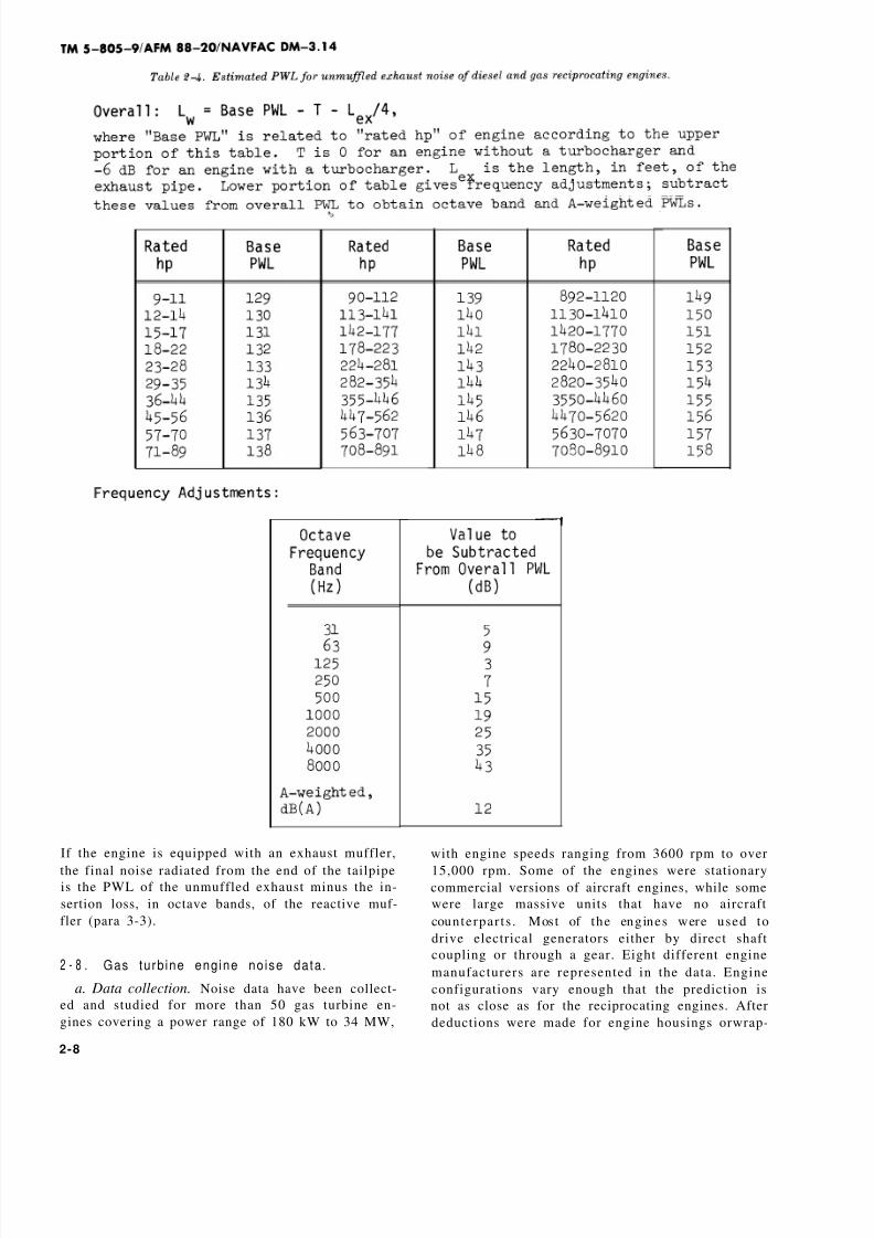
If the engine is equipped with an exhaust muffler,
the final noise radiated from the end of the tailpipeis the PWL of the unmuffled exhaust minus the in-
sertion loss, in octave bands, of the reactive muf-
fler (para 3-3).
2 - 8 . Gas tu rb ine eng ine no ise da ta .
a. Data collection. Noise data have been collect-
ed and studied for more than 50 gas turbine en-
gines covering a power range of 180 kW to 34 MW,
with engine speeds ranging from 3600 rpm to over
15,000 rpm. Some of the engines were stationarycommercial versions of aircraft engines, while some
were large massive units that have no aircraft
counterpar ts . Most of the engines were used to
drive electrical generators either by direct shaft
coupling or through a gear. Eight different engine
manufacturers are represented in the data. Engine
configurations vary enough that the prediction is
not as close as for the reciprocating engines. After
deductions were made for engine housings orwrap-
2-8

8/8/2019 Power Plant Acoustics-b
http://slidepdf.com/reader/full/power-plant-acoustics-b 18/96
pings and inlet and discharge mufflers, the stand-
ard deviation between the predicted levels and the
measured levels for engine noise sources (normal-
ized to unmuffled or uncovered conditions) ranged
between 5.0 and 5.6 dB for the engine casing, the
inlet, and the discharge. In the data that follow, 2
dB have been added to give design protection to
engines that are up to 2 dB noisier than the
average.b. Engine source data. As with reciprocating en-
gines, the three principal noise sources of turbine
engines are the engine casing, the air inlet, and the
exhaust. The overall PWLs of these three sources,
with no noise reduction treatments, are given in
the following equations:
for engine casing noise,
where “rat ed MW’ is th e ma ximum cont inuous full-
load rating of the engine in megawatts. If the man-
ufacturer lists the rating in “effective shaft horse-
p o w e r ” ( e s h p ) , t h e M W r a t i n g m a y b e
approximated by
MW = eshp/1400.
Overal l PWLs, obtained from equat ions 2–4
through 2–6, are tabulated in table 2–5 for a useful
range of MW ratings.
Octave-band and A-weighted corrections for these
overall PWLs are given-in table 2–6.
2-9

8/8/2019 Power Plant Acoustics-b
http://slidepdf.com/reader/full/power-plant-acoustics-b 19/96
(1) Tonal components. For casing and inlet
noise, particularly strong high-frequency soundsmay occur at several of the upper octave bands,
but specifically which bands are not predictable.
Therefore, the octave-band adjustments of table
2–6 allow for these peaks in several different
bands, even though they probably will not occur in
all bands. Because of this randomness of peak fre-
quencies, the A-weighted levels may also vary
from the values quoted.
(2) Engine covers. The engine manufacturer
sometimes provides the engine casing with a pro-tective thermal wrapping or an enclosing cabinet,
either of which can give some noise reduction. Ta-
ble 2-7 suggests the approximate noise reduction
for casing noise that can be assigned to different
types of engine enclosures. The notes of the table
give a broad description of the enclosures.
2–10

8/8/2019 Power Plant Acoustics-b
http://slidepdf.com/reader/full/power-plant-acoustics-b 20/96
The values of table 2–7 maybe subtracted from the
octave-band PWLs of casing noise to obtain the ad-
justed PWLs of the covered or enclosed casing. An
enclosure specifically designed to control casing
noise can give larger noise reduction values than
those in the table.
c. Exhaust and intake stack directivity. F r e q -
uently, the exhaust of a gas turbine engine is di-
rected upward. The directivity of the stack pro-
cabinet.
vides a degree of noise control in the horizontal
direction. Or, in some installations, it may be bene-
ficial to point the intake or exhaust opening hori-
zontally in a direction away from a sensitive receiv-
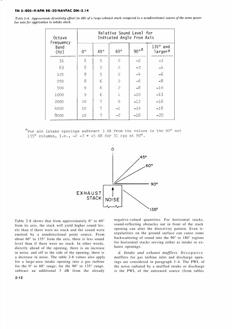
er area. In either event, the directivity is a factorin noise radiation. Table 2–8 gives the approximate
directivity effect of a large exhaust opening. This
effect can be used for either a horizontal or vertical
stack exhausting hot gases.
2-11
8/8/2019 Power Plant Acoustics-b
http://slidepdf.com/reader/full/power-plant-acoustics-b 21/96
Table 2-8 shows that from approximately 0° to 60°
from its axis, the stack will yield higher sound lev-
els than if there were no stack and the sound wereemitted by a nondirectional point source. From
about 60° to 135° from the axis, there is less sound
level than if there were no stack. In other words,
directly ahead of the opening, there is an increase
in noise, and off to the side of the opening, there is
a decrease in noise. The table 2-8 values also apply
for a large-area intake opening into a gas turbine
for the 0° to 60° range; for the 90° to 135° range,
subtract an additional 3 dB from the already
negative-valued quantities. For horizontal stacks,
sound-reflecting obstacles out in front of the stack
opening can alter the directivity pattern. Even ir-
regularities on the ground surface can cause some
backscattering of sound into the 90° to 180° regions
for horizontal stacks serving either as intake or ex-
haust openings.
d. Intake and exhaust mufflers. D i s s i p a t i v e
mufflers for gas turbine inlet and discharge open-
ings are considered in paragraph 3–4. The PWL of
the noise radiated by a muffled intake or discharge
is the PWL of the untreated source (from tables
2-12

8/8/2019 Power Plant Acoustics-b
http://slidepdf.com/reader/full/power-plant-acoustics-b 22/96
2–5 and 2–6) minus the insertion loss of the muffler
used, in octave bands.
2 - 9 . Data fo rms .
Several data forms are developed and illustrated in
the N&V manual. These forms aid in the collection,
organization, and documentation of several calcula-
tion steps that are required in a complex analysisof a noise problem. Instructions for the use of those
data forms (DD Forms 2294 through 2303) are giv-
en in the N&V manual, and blank copies of those
data forms are included in appendix E of that man-
ual. Many of the forms are used in the chapter 4
examples. In addition, two new DD forms are pre-
scribed in this manual.
a. DD Form 2304. DD Form 2304 (Estimated
Sound Power Level of Diesel or Gas Reciprocating
Engine Noise) summarizes the data procedures re-
quired to estimate the PWL of a reciprocating en-
gine (app A). Data for the various steps are ob-
tained from paragraph 2–7 above or from an engine
manufacturer, when such data are available. Parts
A, B, and C provide the PWLs of the engine casing
noise, the turbocharged air inlet noise (if applica-
ble, and with or without sound absorption material
in the inlet ducting), and the engine exhaust noise,
with and without an exhaust muffler.
b. DD Form 2305. DD Form 2305 (Estimated
Sound Power Level of Gas Turbine Engine Noise)
summarizes the data and procedures for estimating
the unquieted and quieted engine casing noise, air
inlet noise., and engine exhaust noise (app A). Ad-ditional engine data and discussion are given in
paragraph 2-8 above, and the insertion losses of a
few sample muffler and duct configurations are giv-
en in paragraphs 3–4 and 3–5.
c. Sample calculations. Sample calculations
using these two new data forms (DD Form 2304
and DD Form 2305) appear in chapter 4.
2-10. Other noise sources.
Gears, generators, fans, motors, pumps, cooling
towers and transformers are other pieces of equip-
ment often used in engine-driven power plants. Re-fer to chapter 7 of the N&V manual for noise data
on these sources.
2-13

8/8/2019 Power Plant Acoustics-b
http://slidepdf.com/reader/full/power-plant-acoustics-b 23/96
CHAPTER 3
NOISE AND VIBRATION CONTROL
FOR ENG INE INSTALLATIO NS
3-1. Engine noise control .
There are essentially three types of noise problemsthat involve engines and power plant operations:
Engine noise has the potential of causing hearing
damage to people who operate and maintain the en-
gines and other related equipment; engine noise is
disturbing to other personnel in the same building
with the engine (or in a nearby building); and pow-
er plant noise is disturbing to residential neighbors
living near the plant. Noise control is directed to-
ward meeting and solving these three types of
problems. In addition to the noise control proce-
dures contained n the N&V manual, this manual
provides material on mufflers, duct lining, vibra-
tion isolation of engines, the use of hearing protec-tion devices (ear plugs and ear muffs), and a special
application of room acoustics in which the indoor
noise escapes outdoors through a solid wall or an
opening in the wall. Each of the three types of
noise problems requires some of these treatments.
a. Noise control for equipment operators.
Equipment operators should be kept out of the en-
gine room most of the time, except when they are
required to be in the room for equipment inspec-
tion, maintenance, repair, or replacement. When
personnel are in the room, and while the equipment
is running, ear protection should be worn, becausethe sound levels are almost certain to be above the
DoD 84–dB(A) sound level limit. Various forms of
engine covers or enclosures for turbine engines are
usually available from the manufacturers. Data on
the noise reduction provided by these marketed
covers can be approximated from table 2–7. A sep-
arate control room beside the engine room or a
suitable personnel booth located inside the engine
room can be used by the operator to maintain visu-
al contact with the engine room and have ready ac-
cess to it, yet work in a relatively quiet environ-
ment. The telephone for the area should be located
inside the control room or personnel booth. An ex-ample of a control room calculation is included in
paragraph 8–3b of the N&V manual and in para-
graph 4–2 of this manual.
b. Noise control for other personnel in the same
(or nearby) building with the engine. Noise control
for this situation is obtained largely by architectur-
al design of the building and mechanical design of
the vibration isolation mounting system. The archi-
tectural decisions involve proper selection of walls,
floors, ceilings, and buffer zones to control noise
escape from the engine room to the adjoining orother nearby rooms (refer to N&V manual). A
reciprocating engine should be fitted with a good
exhaust muf f l e r (preferably ins ide the engine
room), and if the discharge of the exhaust pipe at
its outdoor location is too loud for building occu-
pants or nearby neighbors, a second large-volume,
low-pressure-drop muffler should be installed at
the end of the exhaust pipe. The approval of the
engine manufacturer should be obtained before in-
stallation and use of any special muffler or muffler
configuration, because excessive back-pressure can
be harmful to the engine (para 3–3 discusses re-
active mufflers). A turbine engine will require bothan inlet and a discharge muffler (para 3–4 discusses
dissipative mufflers), and an engine cover (table
2–7) will be helpful in reducing engine room noise
levels. An air supply to the room must be provided
(for room ventilation and primary air for engine
combustion) for both reciprocating and turbine en-
gines, and the muffled, ducted exhaust from tur-
bine engines must be discharged from the building.
Vibration isolation is essential for both types of en-
gines, but reciprocating engines represent the
more ser ious v i b r a t i o n p r o b l e m . L a r ge
reciprocating engines must not be located on upper
floors above critical locations without having veryspecial sound and vibration control treatments. All
reciprocating engines should be located on grade
slabs as far as possible from critical areas of the
building (categories 1 to 3 in table 3-2 of the N&V
manual). Vibration isolation recommendations are
given in paragraphs 3-6, 3-7, and 3–8.
c. Control of noise to neighbors by outdoor
sound paths. If an engine installation is already lo-
cated outdoors and its noise to the neighbors is not
more than about 10 to 15 dB above an acceptable
level, a barrier wall can possibly provide the neces-
sary noise reduction (para 6–5 of the N&V manu-
al). If the existing noise excess is greater than
about 15 dB or if a new installation is being consid-
ered, an enclosed engine room should be used. The
side walls and roof of the room (including doors and
windows) should have adequate TL (transmission
loss; para 5–4 of the N&V manual), ventilation
openings for the room and engine should be acous-
tically treated to prevent excessive noise escape,
and, finally, the total of all escaping noise should
be estimated and checked against the CNR rating
3-1

8/8/2019 Power Plant Acoustics-b
http://slidepdf.com/reader/full/power-plant-acoustics-b 24/96
system for neighborhood acceptance (para 3–3c of
the N&V manual).
3–2. Noise escape through an outdoor w al l .
A lightweight prefabricated garage-like structure
might be considered as a simple enclosure for a
small on-base power plant. The transmission loss of
such a structure might be inadequate, however,
and the enclosure would not serve its intended pur-
pose. A calculation procedure is given here for
evaluating this situation.
a. Noise radiated outdoors by a solid wall. With
the use of the “room acoustics” material in para-
graph 5–3 of the N&V manual and the source data
in paragraphs 2–7 and 2–8 of this manual and in
chapter 7 of the N&V manual, it is possible to cal-
side an. engine room along the wall that radiates
noise to the outdoors. The sound pressure level
L
equation 5–4 in the N&V manual. The N&V equa-tion 5–4 is repeated here:
This equation is modified to become equation 3–1
below for the case of the sound pressure level out-
Constant of the “receiving room”) becomes infinite.
tity 10 log 1/4 is –6 dB. Thus, equation 3–1 is:
L (3-1)
The sound power level LW radiated by this wall is
(from eq. 7-18 in the N&V manual)
(3-2)
where A is the area of the radiating wall, in ft.2
Equation 3–3 combines equations 3–1 and 3-2:
(3-3)
This equation must be used carefully. For a large-
area wall with a low TL in the low-frequency re-
gion, it is possible for equation 3–3 to yield a calcu-
lated value of sound power level radiated by the
wall that exceeds the sound power level of the
source inside the room. This would be unrealistic
and incorrect. Therefore, when equation 3–3 is
used, it is necessary to know or to estimate thePWL of the indoor sound source (or sources) and
not allow the L W of equation 3–3 to exceed that
value in any octave band. When the PWL of the
radiating wall is known, the SPL at any distance of
interest can be calculated from equation 6–1 or ta-
bles 6–3 or 6–4 of the N&V manual. The directivity
of the sound radiated from the wall is also a factor.
If the engine room is free to radiate sound from all
four of its walls, and if all four walls are of similar
construction, the area A in equation 3–3 should be
the total area of all four walls, and the radiated
sound is assumed to be transmitted uniformly in all—
directions. If only one wall is radiating the sound
toward the general direction of the neighbor posi-
tion, it may be assumed that the sound is trans-
mitted uniformly over a horizontal angle that is
120° wide, centered at a line that is perpendicular
to the wall under consideration. This procedure
will give a calculated estimate of the SPL at a
neighbor position fr sound transmitted through a
solid wall whose TL and area are known. Of
course, if a lightweight wall does not have suffi-
cient TL to meet the need, a heavier wall should be
selected.
b. Noise radiated by a wall containing a door or
window. The procedure followed in a above for a
solid wall is readily adaptable to a wall containing a
door or window or other surface or opening having
a TL different from that of the wall. It is necessaryto calculate the effective TLC of the composite wall
and to use TL C in the procedure above. The TLC of
the composite wall may be determined from one of
the methods given in paragraph 5-4e of the N&V
manual .
c. Noise radiated from an opening in a wall. An
opening in an outside wall may be required to per-
mit ventilation of the room or to supply air to an
engine. Noise escaping through that opening might
be disturbing to the neighbors. The sound power
level LW of the escaping noise can be calculated
with the material given in paragraph 7–22 in the
N&V manual, and the SPL at the neighbor position
estimated from the tables 6–3 or 6–4 distance
terms of the N&V manual. If excessive amounts of
noise escape through the opening, a dissipative
muffler should be installed in the opening (para
3-4).
d. Noise radiated from the roof of a building.
Noise from inside a building will escape through
the roof of that building. For a building with a
practically flat roof and a 2- to 5-ft.-high parapet
around the edge of thereof, the noise radiated from
the roof has a significant upward directivity effect.
This results in a lower amount of sound radiatedhorizontally from the roof surface. There are no
measured field data for the directivity effect of
roof-radiated sound, but a reasonable estimate of
this effect is given in table 3–1. Without a parapet
around the roof, slightly larger amounts of sound
are radiated horizontally; and a sloping room radi-
ates still higher amounts of sound horizontally.—
3-2

8/8/2019 Power Plant Acoustics-b
http://slidepdf.com/reader/full/power-plant-acoustics-b 25/96
Since the directivity is also related to wavelength 3-3. React ive m uff lers for reciprocat ing
of sound, large values of roof dimension D have engines.higher vertical directivity and therefore a greater
reduction of horizontally radiated sound t han do Reactive mufflers are used almost entirely for gas
smaller values of D. All these variations are repre- and diesel reciprocating engine exhausts. Reactive
sented in table 3–1. The total PWL of the sound ra- mufflers usually consist of 2 or 3 large-volume
diated from a roof is es t imated with t he use of chambers containing an internal labyrinth-l ike ar-
equation 3–3, where TL is the transmission loss of rangement of baffles, compartments, and per-
the roof structure and A is the area of the exposed forated tubes and plates. Reactive mufflers smooth
roof. The horizontally radiated sound power
the total PWL minus the table 3–1 values.
is then out the flow of impuls ive-exhaust d ischarge and, by
the arrangement of the internal components, at-
3-3

8/8/2019 Power Plant Acoustics-b
http://slidepdf.com/reader/full/power-plant-acoustics-b 26/96
tempt to reflect sound energy back toward the the larger the muffler, the greater the insertion
source. There is usually no acoustic absorption ma- loss or noise reduction. Table 3–2 gives the approx-
terial inside a reactive muffler. Most manufactur- imate insertion loss of the three classes of mufflers.
ers of these exhaust mufflers produce three grades The PWL of the noise radiated by a muffled engine
or sizes, based on the amount of noise reduction exhaust is the PWL of the unmuffled exhaust mi-
provided. Generally, for a particular engine use, nus the insertion loss of the muffler.
a. Muffler grades and sizes. Typically, the three
different grades of mufflers are labeled with names
that indicate the relative degree of criticalness of
th e n oise problem involved, su ch a s ’’comm ercial,”
“res ident i a l ” and “suburban ,” or “s t andard ,”
“semicritical” and “critical,” or similar series of
names and models. Very approximately, the over-
all volume of the middle-size or second muffler in
the series is about 1.4 to 1.6 times the volume of
the smallest or first muffler in the series, while the
volume of the largest or third muffler in the series
is about 2 to 2.5 times the volume of the first muf-
fler. An engine manufacturer will usually recom-
mend a maximum length and minimum diameter
exhaust pipe for an engine, as these influence the
back-pressure applied to the engine exhaust. Low-
pressure-drop mufflers are normally required for
turbocharged engines because the turbocharger
has already introduced some pressure drop in the
exhaust line.
3 -4
b. Caution. The insertion loss values of table 3-2
are offered only as estimates because other factors
in the installation may affect the noise output of
the engine—such factors as the exha ust pipe di-
mensions and layout, back-pressure in the system,
and location of the muffler. The engine manufac-
tu rer ’s appr oval or suggestions should be obta ined
for unusual muffler arrangements.
3-4. Diss ipat ive muf f lers .
A gas turbine engine typically requires a muffler at
the air intake to the engine and another muffler at
the engine exhaust . Depending on the ar range-
ment, either a reciprocating or a turbine engine
may also require some muffling for ventilation air
openings into the engine room, and some of the
packaged gas turbine units may require some
muffling for auxiliary fans, heat exhangers or for
ventilation openings into the generator and/or gear
compartment. The mufflers required for these situ-

8/8/2019 Power Plant Acoustics-b
http://slidepdf.com/reader/full/power-plant-acoustics-b 27/96
ations are known as “dissipative” mufflers. As the
name implies, dissipative mufflers are made up of
various arrangements of sound absorbent material,
which actually absorbs sound energy out of the
moving air or exhaust stream. The most popular
configuration is an array of “parallel baffles” placed
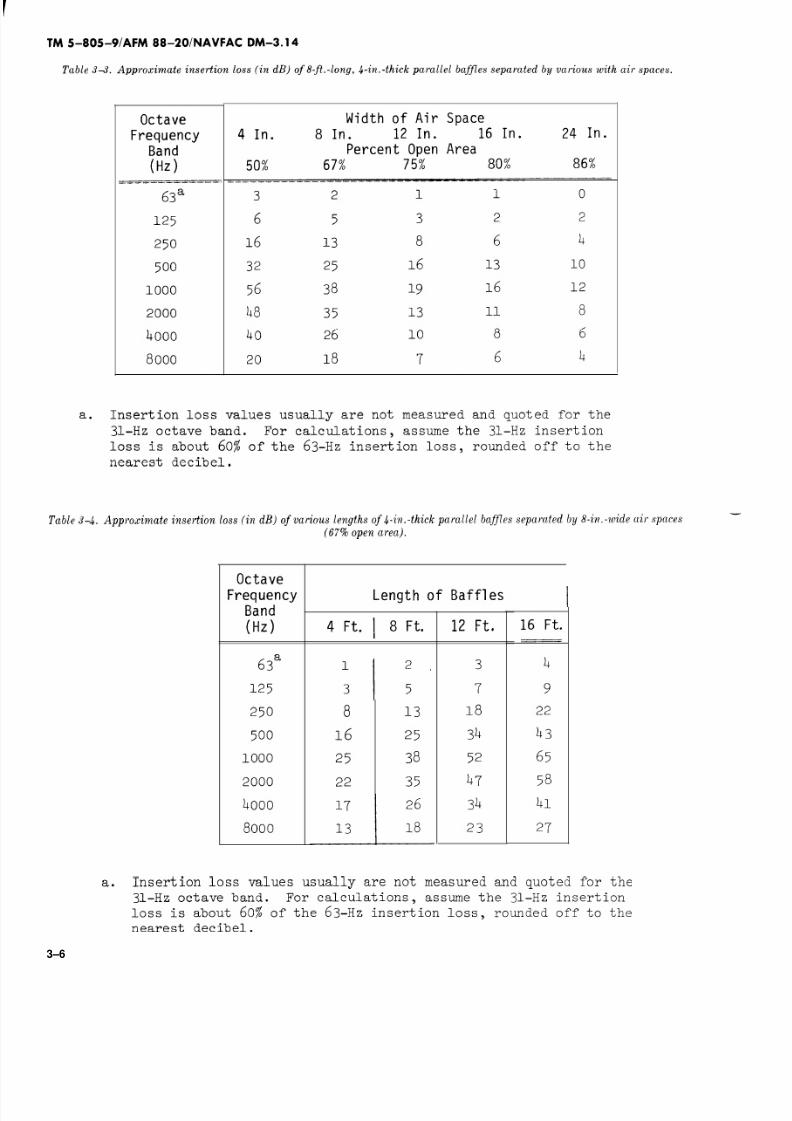
in the air stream. The baffles may range from 2-in.
to 16-in. thick, and are filled with glass fiber or
mineral wool. Under severe uses, the muffler ma-terial must be able to withstand the operating tem-
perature of the air or gas flow, and it must have
adequate internal construction and surface protec-
tion to resist the destruction and erosion of high-
speed, turbulent flow. These mufflers should be ob-
ta ined f r om a n exper ien ced , r epu ta ble
manufacturer to insure proper quality of materials,
design, workmanship, and ultimately, long life and
durability of the unit. Dissipative mufflers are di-
vided here into two groups: the special custom-
designed and constructed mufflers for gas turbine
engines and other heavy-duty applications, and
ventilation-duct mufflers that are stock items man-
ufactured and available from several companies.
a. Gas turbine mufflers. Noise from the air inlet
of a gas turbine is usually strong in the high-
frequency region and is caused by the blade pas-
sage frequencies of the first one or two compressor
stages of the turbine. Thin parallel baffles of ap-
proximately 4-in. thickness, with 4-in. to 6-in. air
spaces between baff les , are qui te effect ive in
reducing high-frequency sound. The discharge
noise of a gas turbine engine, on the other hand, is
strong in the low-frequency region. Mufflers must
have large dimensions to be effective in the low-frequency region, where wavelength dimensions
are large (para 2–6b of the N&V manual). Thus,
these baffles may be 6-in. to 18-in. thick, with 8-in.
to 16-in. air spaces between baffles, and have rug-
ged construction to withstand the high tempera-
ture and turbulent flow of the engine discharge.
Depending on the seriousness of the noise prob-
lems, mufflers may range from 8 ft. to 20 ft. in
length, and for very critical problems (i. e., very
close neighbors), two different 12- to 18-ft. muf-
flers (different baffle dimensions) may be stacked
in series to provide maximum insertion loss over a
broad frequency range.
(1) When large amounts of loss are required,
baffles are installed at close spacings with perhaps
only 30 to 50 percent open air passage through the
total muffler cross section. This, in turn, produces
a high pressure drop in the flow, so the final muf-
fler design represents a compromise of cost, area,
length, pressure drop, and frequency response.
Pressure drop of flow through the muffler can usu-
ally be reduced by fitting a rounded or pointed end
cap to the entrance and exits ends of a baffle.
(2) The side walls of the chamber that contains
the muffler must not permit sound escape greater
than that which passes through the muffler itself.
Thus, the side walls at the noisy end of the muffler
should have a TL at least 10 dB greater than the
insertion loss of the muffler for each frequency
band. At the quiet end of the muffler, the TL of the
side walls can be reduced to about 10 dB greaterthan one-half the total insertion loss of the muffler.
(3) In the contract specifications, the amount
of insertion loss that is expected of a muffler should
be stated so that the muffler manufacturer may be
held to an agreed-upon value. It is more important
to specify the insertion loss than the dimension and
composition of the muffler because different manu-
facturers may have different, but equally accepta-
ble, fabrication methods for achieving the values.
(4) Operating temperature should also be stat-
ed. When dissipative mufflers carry air or gas at
elevated temperatures, the wavelength of sound is
longer, so the mufflers appear shorter in length
(compared to the wavelength) and therefore less
effect ive acoust ical ly (para 2-6b of the N&V
manual) .
(5) AS an aid in judging or evaluating muffler
performance, tables 3–3 through 3–8 give the ap-
proximate insertion loss values to be expected of a
number of muffler arrangements. Values may vary
from one manufacturer to another, depending on
materials and designs.
3-5
8/8/2019 Power Plant Acoustics-b
http://slidepdf.com/reader/full/power-plant-acoustics-b 28/96
3–6

8/8/2019 Power Plant Acoustics-b
http://slidepdf.com/reader/full/power-plant-acoustics-b 29/96
3-7

8/8/2019 Power Plant Acoustics-b
http://slidepdf.com/reader/full/power-plant-acoustics-b 30/96

8/8/2019 Power Plant Acoustics-b
http://slidepdf.com/reader/full/power-plant-acoustics-b 31/96
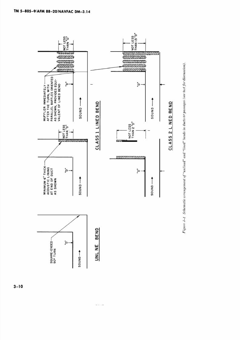
b. “Lined” and “unlined” bends in turbine
stacks. When a long duct or passageway contains a
square-ended 90° turn, there is a tendency for
sound traveling in that duct to be reflected back to-
ward the direction from which it came. Because
high-frequency sound is more “directional” (be-
haves more nearly as a beam of light), it is more
readily reflected back by the end wall of the 90°
turn and less sound is transmitted around the cor-ner. Low-frequency sound “bends” around the turn
more readily, so this reflection effect is less pro-
nounced. The attenuation provided by a square-
ended 90° turn can be
adding a thick lining of acoustic absorption materi-
al at the end of the turn (facing the oncoming sound
wave), extending into the duct past the turn for a
length of one or two times the average width of the
duct. A long muffler, located immediately past the
turn, also serves to simulate a lined bend. Table
3–9 gives the estimated insertion loss of unlined
and lined bends, and figure 3–1 shows schematical-
ly the bend configurations. The orientation of theparallel baffles of a muffler located just past a turn
should be as shown in figure 3–1 to achieve the
Class 1 and Class 2 lined bend effects.
increased not i ceably by
3 - 9
8/8/2019 Power Plant Acoustics-b
http://slidepdf.com/reader/full/power-plant-acoustics-b 32/96

8/8/2019 Power Plant Acoustics-b
http://slidepdf.com/reader/full/power-plant-acoustics-b 33/96
Turning vanes in the 90° square turn reduce the in-
sertion loss values. If turning vanes are used, only
one-half the insertion loss values of table 3–9 may
be used for the 63- through 500-Hz bands and only
one- four th the va lues fo r the 1000- th rough
8000-Hz bands. When a muffler is used at the turn,
full attenuation of the muffler is realized as well as
the additional loss due to the lined turn.
c. Ventilation-duct mufflers. For duc ted a i r -
handling, ventilation, or air-conditioning systems,
packaged duct mufflers can be purchased directly
from reputable acoustical products suppliers. Their
catalogs show the available dimensions and inser-
tion losses provided in their standard rectangular
and circular cross-section mufflers. These pack-
aged duct mufflers are sold by manufacturers in
3-ft., 5-ft., and 7-ft. lengths. They are also usually
available in two or three “classes,” depending on
attenuation. The mufflers of the higher insertion-
l0SS class typically have only about 25% to 35%
open area, with the remainder of the space filled
with absorption material. The lower insertion-loss
classes have about 50% open area. The mufflers
with the larger open area have less pressure drop
and are known as “low-pressure-drop units. ” The
mufflers with the smaller open area are known as“high-pressure-drop units. ” When ordering special-
purpose mufflers, one should state the speed and
the temperature of the air or gas flow, as these
may require special surface protection and special
acoustic filler materials. The approximate insertion
losses of a representative group of ventilation-duct
mufflers are given in table 3–10. Individual suppli-
ers can give data for their specific products.
There is no precise schedule of self-noise as a func- F or
tion of exit speed for large mufflers, but the follow- sity
ing rules -of-thumb for exhaus t stacks of tu rbine en- flow
gines are offered. For installations in relatively mal
hot exhausts, the exhaust gas is of lower den-
and consequently has a higher total volume
for a given mass flow than would exist at nor-
ambient temperature. The manufacturers of
3–1 1

8/8/2019 Power Plant Acoustics-b
http://slidepdf.com/reader/full/power-plant-acoustics-b 34/96
duct mufflers can usually furnish self-noise data for
their products.
e. Muffler pressure drop. In any installation
where exhaust or inlet pressures are of concern,
the designer should request the muffler manufac-
turer to provide pressure-drop data for the pro-
posed mufflers, and these values should rechecked
and approved by the engine manufacturer.
3–5. Vent i la t ion duct l in ing.
Duct lining is used to absorb duct-transmitted
noise. Typically, duct lining is 1 in. thick. Long
lengths of duct lining can be very effective in ab-
sorbing high-frequency sound, but the thin thick-
nesses not very effective for low-frequency absorp-
t i o n . T h e A S H R A E H a n d b o o k a n d P r o d u c t
Directory-Fundamentals (app. B) can be used to
estimate the attenuation of duct lining. Lined 90°
square turns are very effective in reducing high-
frequency noise. Turning vanes or rounded 90°
turns, however, provides neglible amounts of high-frequency loss.
3–6. V ibrat ion iso la t ion of rec iprocat ing
eng ines.
Vibrat ion isolat ion of reciprocat ing engine
assemblies is discussed for two general locations:
on an on-grade slab, such as in a basement or
ground level location, and on an upper floor of a
multifloor building. Suggestions given h ere are
based on acoustical considerations only; these are
not intended to represent structural design re-
quirements. These suggestions apply to both theengine and all attached equipment driven by the
engine. It is assumed that the mechanical engineer,
st ructural engineer , or equipment manufacturer
will specify a stiff, integral base assembly for the
mounting of the equipment and that all equipment
will be properly aligned. The base assembly should
be stiff enough to permit mounting of the entire
equipment load on individual point supports, such
a s “soft” steel springs. E qu i pm en t i n s t a l l a t i ons
that involve close-by vibration-sensitive equip-
ment, instruments, or processes are beyond the
generalized recommendations given here. The ba-
sics of vibration isolation (criteria, materials, and
approaches) are given in chapters 4 and 9 of the
N&V manual. -The term “engine assembly” is used
here to include the engine, all driven equipment
(such as gear, generator, compressor, etc.), and
the engine base. The term “engine base” is used
here to include a stiff steel base or platform that
supports the engine assembly and a concrete iner-
tia block to which the steel base is rigidly attached.
a. Concrete inertia block. A concrete iner t ia
block is required under each engine assembly un-
less stated otherwise. The concrete inertia block
adds s t ab i l i t y to the ins t a l l a t ion and r educes
vibration. For reciprocating engine speeds under
about 360 rpm, the weight of the concrete inertiablock should be at least 5 times the total weight of
the supported load; for engine speeds between 360
and 720 rpm, the inertia block should weigh at
least 3 times the total weight of the supported load;
and for engine speeds above about 720 rpm, the in-
ertia block should weigh at least 2 times the total
weight of the supported load. Even small inertia
blocks should be thick enough to provide a stiff
base for maintaining alignment of equipment when
the inertia block is mounted on springs around the
perimeter of the block. Additional vibration isola-
tion details are given below as a function of location
and engine speed and power.
b. On-grade location. The chart in figure 3–2
shows the paragraphs below that give recom-
mended vibration isolation treatments for various
combinations of engine speed and power rating.
3–12

8/8/2019 Power Plant Acoustics-b
http://slidepdf.com/reader/full/power-plant-acoustics-b 35/96
(1) For engines under 600 rpm (for any size)
and over 1200 hp (for any speed).
(a) No vibration isolation of the engine as-
sembly is required if there is no category 1 area
(table 3-2 in N&V manual) within a horizontal dis-
tance of 500 ft., or no category 2 or 3 area within
250 ft., or no category 4 or 5 area within 150 ft. of
the engine base. It is good practice, nevertheless,
to give the engine base its own footings, separated
from the footings of the generator room, with a
structural break between the floor slab or floor
grille of the generator room and the engine base.
( I t i s assumed th roughout th i s schedule tha t
feelable vibration is acceptable in category 6 areas.
If this is not an acceptable assumption, category 6
should be considered along with categories 4 and
5.)
(b) For distances closer than those listed in
(a) above, for the indicated categories, the engine
base should be supported on steel spring vibration
isolation mounts that have a static deflection of atleast 1 in. for engine speeds above 600 rpm or 2 in.
for engine speeds of 301 to 600 rpm or at least 4 in.
for engine speeds of 200 to 300 rpm.
(c) The steel springs of (b) above should
rest on pads of ribbed or waffle-pattern neoprene if
the engine assembly is located within 200 ft. of a
catagory 1 are or within 100 ft. of a category 2 or 3
area or within 50 ft. of a category 4 or 5 are. Pad
details are given in paragraph d(1) below.
(2) For engines above 600 rpm and under 1200
hp (except (3) below).
(a) No vibration isolation of the engine as-
sembly is required if there is no category 1 area
(table 3-2 in the N&V manual) within 300 ft., or no
category 2 or 3 area within 150 ft., or no category 4
or 5 area within 75 ft. of the engine base. It is good
practice, nevertheless, to give the engine base its
own footings, separat ed from the footings of the
generator room, with a structural break between
the floor slab or floor grille of the generator room
and the engine base. (It is assumed throughout this
schedule that feelable vibration is acceptable in
category 6 ar eas. If this is not an acceptable as-
sumption, category 6 should be considered along
with categories 4 and 5.)
(b) For distances closer than those listed in
(a) above, for the indicated categories, the engine
base should be supported on steel spring vibration
isolation mounts that have a static deflection of at
least 2 in. for engine speeds of 600 to 1200 rpm orat least 1 in. for engine speeds above 1200 rpm.
(c) The steel springs of (b) above should
rest on pads of ribbed or waffle-pattern neoprene if
the engine assembly is located within 200 ft. of a
category 1 area or within 100 ft. of a category 2 or
3 area or within 50 ft. of a category 4 or 5 area. Pad
details are given in paragraph d(1) below.
(3) For engines above 1200 rpm and under 400hp. A concrete inertia block is not required for this
3–13

8/8/2019 Power Plant Acoustics-b
http://slidepdf.com/reader/full/power-plant-acoustics-b 36/96
engine speed and power combination, although it
would still be beneficial if used. All other recom-
mendations of (2) above apply to the installation. If
the concrete block is eliminated, a substantial
housekeeping pad should be provided under the en-
gine assembly, and the engine assembly should be
mounted on a steel frame that is stiff enough to
permit use of individual steel spring isolators un-
der the steel frame without introducing equipment
misalignment.
c. Upper-floor location. It is strongly suggested
that no reciprocating engine assembly remounted
on any upper floor location of a wood-frame build-
ing and that no reciprocating engine over 600 hp or
under 1200 rpm be installed on an upper floor of a
steel or concrete building. If an engine rated under
600 hp and operating above 1200 rpm is installed in
an upper floor location in a building containing cat-
egory. 1–5 occupancy areas (table 3–2 of the N&V
manual) , the fol lowing suggest ions should be
applied.
(1) The entire engine assembly should bemounted rigidly to a concrete inertia block having a
weight at least 3 times the total weight of the sup-
ported load. The concrete inertia block may be
eliminated, if desired, for any engine of less than
100 hp that is located two or more floors away from
a category 1 or 2 area, or that is not located direct-
ly over a category 3 area. If a concrete inertia
block is used, it should be thick enough to assure
stiffness and good alignment to the entire assem-
bly. Its area should be at least as large as the over-
all area of the equipment that it supports. If the
engine drives a refrigeration compressor that is
connected directly to its evaporator and condensercylinders, all this equipment should be mounted to-
gether onto the same concrete block. The bottom of
the inertia block should rest at least 4 in. above the
top of the housekeeping pad or the structure slab.
If a Type 5 floating-floor slab is involved (para 5–5e
of the N&V manual), this 4-in. air space under the
concrete inertia block should be covered with 2-in. -
thick low-cost glass fiber or mineral wool. The en-
gine assembly is not to be mounted on the floating-
floor slab. If a concrete inertia block is not used, a
substantial housekeeping pad should be provided
under the engine assembly, and the engine assem-
bly should be mounted on a rigid steel frame that isstiff enough to be supported off the floor on indi-
vidual steel spring isolators without introducing
stability or alignment problems.
(2) The concrete inertia block or the stiff steel
frame of (1) above should be supported off the
structure floor slab with steel spring vibration iso-
lation mounts having minimum 2-in. static deflec-
tion under load.
(3) Each steel spring should rest on a block of
ribbed or waffle-pattern neoprene pads, as de-
scribed in d(l) below.
( 4 ) T h e s t r u c t u r e f l o o r s u p p o r t i n g a
reciprocating engine assembly should be at least
10-in. thick and made of dense concrete (140 to 150
lb/ft .3). Where possible, the engine should be lo-
cated over primary or secondary beams supporting
the structure slab.
(5) Proper airborne noise control must be pro-vided between the engine room and all nearby
occupied areas, as discussed in chapter 5 of the
N&V manual.
d. Other general recommendations. The follow-
ing general recommendations apply to all engine in-
stallations requiring vibration isolation.
(1) Ribbed or waffle-pattern neoprene pads
should be made up of three or four layers of the
material, giving a total thickness of approximately
1 in. of neoprene. The area of the pads should be
such as to provide the surface loading recom-
mended by the pad manufacturer. For critical loca-tions, provision should be made to permit replace-
ment of the pads after about 25 years, as the pad
material may deteriorate by that time. An arrange-
ment for providing layers of neoprene pads under a
spring base is seen in figure 9–1 of the N&V
manual .
(2) For an isolated engine assembly, there
should be no structural, rigid connections between
the engine assembly and the building proper. This
includes piping, conduit, and ducts to and from the
assembly.
(a) A long bellows-type thermal expansion
joint in the exhaust piping meets this requirement,as does a flexible connection in the inlet-air ducting
to the engine.
(b) Piping to the engine assembly may con-
tain long flexible connections (length at least 6
times the outside diameter of the piping) that are
not short-circuited by steel bars that bridge the
flanges of the flexible connections; or piping may
be used without flexible connections, if the piping
is supported on vibration isolation hangers or
mounts for a distance along the pipe of at least 200
pipe diameters. The vibration isolation hangers
should have a static deflection of at least one-half
the static deflection of the mounts that support theengine base. If steel springs are used in the pipe
hangers, neoprene or compressed glass fiber pads
should be in series with the springs.
(c) Electrical bus bars from the generator
should either contain a 6-ft. length of braided, flex-
ible conductor across the vibration isolation joint,
or be supported from resilient hangers for a dis-
tance o f about 50 f t . f rom the i so la ted assembly .—
3-14

8/8/2019 Power Plant Acoustics-b
http://slidepdf.com/reader/full/power-plant-acoustics-b 37/96
(3) Where steel springs are used, unhoused
stable steel springs are preferred. If housed or en-
closed springs must be used, special attention must
be given to the alignment of the mounts so that
they do not tilt or bind in any direction within their
housings. Further, there should be some visual
means to check the spring mount in its final loca-
tion to be certain that binding or tilting does not
tak e place.e. Special situations. The recommendations giv-
en in paragraph 3–6 will provide adequate cover-
age for most typical equipment installations. How-
ever, general rules cannot cover all marginal and
complex variations. For unusual installations or
unfamiliar conditions, it is advisable to have the as-
sistance of a vibration or acoustical consultant ex-
perienced with this equipment . Vibrat ion problems
are sometimes quite complex and unpredictable.
3–7. Vibrat ion isolat ion of turbine engines.
Typica l ly , the smal le r gas tu rb ine eng ine-
generator sets (under about 5 MW) are mounted,
transported, and installed as complete assemblies
on steel-frame “skid-like” structures, and the large
gas turbine systems (over about 5 MW) are in-
stalled at the site on long, stiff steel-beam bases,
which in turn rest on concrete footings or concrete
mats, The turbine speeds are very high (typically
3600 to 6000 rpm, some up to 25,000 rpm), and the
alignment of turbine, gear, and generator is criti-
cal. The absence of rotary unbalance at these
speeds is mandatory; hence, there is little or no vi-
b r a t i o n c om p a r e d t o th e vibr a tion of a
reciprocating engine. The steel beams of the largeturbine engine assemblies require their concrete
footings for additional longitudinal stiffness and
s ys t e m a l ig n m en t , s o s t e el s p r in g s a r e n o t
recommended as point supports along the steel
beams unless the manufacturer specifically pro-
poses such mounts for critical installations. In-
stead, it is suggested that the engines be separated
from any critical areas by adequate distance. Dis-
tance requirements set by the airborne noise prob-
lem will probably assure the adequate distances
needed for vibration control. For these same rea-
sons, the large units (above about 5 MW) should
not be installed in upper-floor locations. The fol-lowing recommendations apply to turbine engine
installations.
a. On-grade locations.
(1) “Skid-mounted” engine-generators (under
about 5 MW).
(a) No vibration isolation of the assembly is
required if there is no category 1 area within 200
ft., or no category 2 or 3 area within 100 ft., or no
category 4 or 5 area within 50 ft. of the engine as-
sembly. Table 3–2 in the N&V manual explains
these category designations.
(b) If the engine must be located closer than
the distances listed above, for the indicated catego-
ries, the skid-type base should be mounted on
ribbed or waffle-pattern neoprene pads. The pads
should be made up of at least three layers of mate-
rial having a total thickness of about 1 in. (para
3–6d(l) above). Pipes, ducts, and conduit to the
engine-generator set should either contain flexible
connections or be supported : from resilient hangers
for a distance of at least 25 ft. from the assembly.
The engine manufacturer must approve the isola-
tion mounting of the assembly.
(2) “On-site-assembled” generators (over about 5 MW).
(a) No vibration isolation of the assembly is
required if there is no category 1 area within 400
ft., or no category 2 or 3 area within 200 ft., or no
category 4 or 5 area within 100 ft. of the engine as-
sembly. Even greater distances are desirable.
(b) If the engine must be located closer thanthe distances listed above, for the indicated catego-
ries, special concern must be given to the installa-
tion; and an agreeable design must be devised and
approved by both the engine manufacturer and a
vibration engineer or acoustics consultant. Such a
design requires detailed knowledge about the spe-
cific engine and engine base involved and cannot be
covered by generalizations in this manual.
b. Upper-floor location.
(1) Skid-mounted, engine-generators (under
about 5 MW). These installations should be vibra-
tion isolated in accordance with table 9–11 in the
N&V manual. If gas turbine engines are used tod r i v e o t h e r t y p e s o f e q u i p m e n t , s u c h a s
reciprocating or centrifugal refrigeration or gas
compressors, the recommendations of tables 9–3 or
9–5 (whichever is most nearly applicable) of the
N&V manual should be used.
(2) “On-site-assembled” generators (over about 5 MW). These units should not be installed
on upper floor locations without the assistance of a
vibration or acoustics specialist.
3–8. Vibrat ion isolat ion of auxi l iary
equipment .
Ventilating fans, cooling towers, pumps, and com-
pressors may also be involved with an engine-
generator system. Vibration isolation of this auxil-
iary equipment should be in accordance with
chapter 9 of the N&V manual.
3-9. Use of hear ing protect ion devices.
Personnel working in engine-generator rooms are
exposed to hazardous noise levels as defined by
3-15

8/8/2019 Power Plant Acoustics-b
http://slidepdf.com/reader/full/power-plant-acoustics-b 38/96
document is given in paragraph 3-4d of the N&V
manual. The use of approved ear plugs or ear muffs
is mandatory for personnel in engine rooms during
engine operation. Signs specifying the use of hear-
ing protection devices should be placed at each en-
trance to the engine room. Typically, well-fitted
ear plugs or ear muffs have insertion loss values of
about 15 to 20 dB in the 63- to 250-Hz bands, risingwith frequency to about 25 to 35 dB in the 1000- to
8000-Hz bands. Poorly fitted devices may have
only 10 to 15 dB insertion loss values. When used
in series, ear plugs plus ear muffs can increase the
IL by about 10 dB over that of either ear plugs or
ear muffs alone.
3-10. Nondisturbing warning and paging
s y s t e m s .
Outdoor audible paging systems are frequently an-
noying to neighbors. Indoor paging or warning sys-
tems frequently are so loud that they contribute to
the hearing damage problem, or they may be so
quiet that they cannot be heard in a noisy engine
room. Consideration should be given to the use of
one or more of the following nondisturbing warning
or paging systems: flashing lights (possibly coded
to convey special meanings), “walkie-talkies” for
outdoor personnel, “beeper” paging systems for
outdoor or indoor personnel, limited power and
directivity for outdoor loudspeakers, and automatic
shut-off of outdoor paging systems at nighttime.
3–11. Quality of analysis procedure.
A detailed acoustical evaluation brings togetherlarge amounts of data, each component of which is
subject to small errors or unknowns. Paragraph
8–5 in the N&V manual discusses this situation as
it relates to the quality of the final answer. In sum-
mary, it states that the data and procedures have
been found to produce satisfactory results in many
different situations and applications, but that un-
usual circumstances statistically can produce unex-
pected results. Unexpected results can be avoided
or minimized by encouraging a slightly conserva-
tive approach in acoustical designs. Design decision
arising out of the use of several of the data forms
(app. A) are often based on the following four cate-
gories used to describe the relative reliability or
confidence level of the acoustical design. The de-
signer should weigh carefully the applicability of
these four categories to any particular evaluation.
a. “Preferred”. The design equals or surpasses
the requirements of the analysis in all frequency
bands.
b. “Acceptable”. The design produces no more
than the following noise excesses above the design
goal: 4 dB in the 31-, 63-, and 125-Hz bands, 3 dB
in the 250-Hz band, or 2 dB in all the higher fre-
quency bands.
c. “Marginal”. The design produces one or more
of the following noise excesses above the design
goal, in any or all frequency bands: 5 to 7 dB in the
31-, 63-, and 125-Hz bands, 4 to 6 dB in the 250-Hz
band, or 3 to 5 dB in all the higher frequency
bands.
d. “Unacceptable”. The design produces noise
excesses above the design goal that are higher in
any frequency band than those values listed for
“marginal” in c above. It is strongly recommendedthat an “unacceptable” design not be permitted.
3–1 6

8/8/2019 Power Plant Acoustics-b
http://slidepdf.com/reader/full/power-plant-acoustics-b 39/96
TM 5-805-91AFM
CHAPTER 4
EXAMPLES OF SOUND ANALYSIS PROCEDURE
88-201 NAVFAC DM-3.14
4–1. Summary of examples.
Two engine-generator installations are studied in
sufficient detail to illustrate the versatility of the
sound analysis procedure. The first installation is
an on-grade power plant with two engine rooms, a
control room, and some nearby office space in the
same bui lding. A v a r i e t y o f g a s o r d i e s e l
reciprocating engines drive the generators. On-
base housing is located relatively close to the plant.
The second installation is a single conventional
packaged gas turbine engine generator with its
vertical intake and exhaust stacks fitted with muf-
flers to meet the noise requirements of a nearby
military base hospital. Both examples are fabri-
cated only to illustrate the methodology of this
manual; they do not represent proven structural or
operating layouts.
4–2. Example of an on-grade gas or diesel
eng ine ins ta l l a t i on .
a. Description of the power station. A power sta-
tion, shown in figure 4-1, is to be located 1200 ft.
from on-base housing.
4-1

8/8/2019 Power Plant Acoustics-b
http://slidepdf.com/reader/full/power-plant-acoustics-b 40/96
Engine Room No. 1 contains two engines and has
space for a third. Each engine has a 3500-hp rating,
operates at 450 rpm, and can use either natural gas
or d i es e l fu e l. T h es e in - l in e e n gi n es a r e
turbocharged, with approximately 15-ft.-long in-
take ducts to the air cleaners located out of doors,
as shown. The engine exhausts are fed through
50-ft. pipes to “best grade” low-pressure-drop ex-
haust mufflers, also out of doors. Engine Room No.
2 contains one 900-hp V-12 engine that operates at
1800 rpm and one 1600-hp V-16 engine that oper-
ates at 900 rpm. Another V-16 engine may be
added later in this room. The V-12 engine has a
turbocharger that draws intake air directly from
the room through an air filter chamber, and the
V-16 engine is fitted with a Roots Blower that
draws air from the room without benefit of a muf-
fler intake arrangement. Engine combustion air is
drawn into this room through a side wall opening
that is to be fitted with a muffler if necessary.
These engines are fitted with “best grade” exhaust
mufflers through 30-ft.-long exhaust pipes. Low-p r e s s u r e - d r o p m u f f l e r s a r e u s e d w i t h t h e
turbocharged engines, and h igh-pressure -drop
mufflers are used with the Roots Blower engines.
(l) Personnel access doors are provided be-
tween the Main tenance Shop and the Engine
Rooms, emergency exit doors are provided in the
south walls of the Engine Rooms, and large
equipment-access roll doors are provided between
the Engine Rooms and a large “Receiving, Stor-
age, Transfer Room” across the south side of the
building.
(2) The Offices and Lunch Room and Lounge
at the north side of the building are partially pro-tect ed ‘from En gine Room n oise by “buffer” ar eas :
The Toilet and Locker Rooms protect the Lunch
Room and Lounge, and the corridor protects the
group of Offices.
(3) The Maintenance Shop and the second-floor
Control Room overlooking the two Engine Rooms
must be evaluated in order to determine the re-
quirements for walls, doors, and windows common
with the Engine Rooms, with special emphasis be-
ing given to the size and make-up of the viewing
windows in order to achieve an acceptable “SIL”
(speech interference level) condition in the Control
Room because of the present and future engines in
the two Engine Rooms.
(4) A Mechanical Equipment Room provides
ventilation air for the Engine Rooms as the outside
and inside air temperatures dictate. The Control
Room and Offices are served by a separate system
to eliminate the possible feed-through of Engine
Room noise into the quieter parts of the building.
The engine air inlet in the wall of Engine Room
No. 2 is always open in the event of failure of the
bui ld ing vent i l a t ion sys tem.
b. Sound level requirements.(1) Engine Rooms. There are no current state-
of-the-art. developments that will reduce engineroom noise to the nonhazardous levels of less than
85 dB(A), so personnel using these rooms must use
hearing protection equipment (approved ear plugs
or ear muffs) when their daily exposures exceed
the al lowable l imits (para 3-4d of the N&V
manual) .
(2) Maintenance Shop. Sound levels here shall
not exceed 84 dB(A), for purposes of hearing pro-
tection, and it is preferred that the speech inter-
ference level (SIL) due to Engine Room noise not
exceed 60 dB when Engine Room doors are closed
(para 3-2d of the N&V manual describes SIL).
(3) Control Room. Sound levels here shall notexceed 84 dB(A), and it is preferred that the SIL
due to Engine Room noise not exceed 55 dB when
all engines, existing and future, are in operation.
(4) Offices. Engine Room noise heard in the of-
fices shall not exceed NC–40 levels when all doors
are closed (para 3–2a of the N&V manual).
(5) On-base housing. Power plant noise shall
not exceed NC–25 levels indoors at the base hous-
ing located about 1200 ft. to the east of the plant,
when all exterior doors of the plant are closed.
c. Engine Room noise levels. DD Form 2304 is
used to estimate the PWL of each engine. DDForm 2295 (Room Constant by Estimation Meth-
od. ) is used to estimate the Room Constant of each
room. DD Form 2296 (Mechanical Equipment
Room SPL Caused by Equipment) and DD Form
2297 (Summation of All Equipment SPLs on One
Wall or Surface of the ME R.) are used to estimate
the SPLs at the Engine Room walls that are com-
mon to the other rooms of interest (the Mainte-
nance Shop, the Control Room, and the corridor
separating the Offices from Engine Room No. 2).
(1) Engine PWLs. The accompanying filled-in
copies of DD Form 2304 give the estimated PWLs
of the three noise components of each of the three
engine types involved here. Only the engine casing
noise (Part A) radiates into the Engine Rooms. For
identification, see figures 4–2 through 4–4 for
samples.
4-2

8/8/2019 Power Plant Acoustics-b
http://slidepdf.com/reader/full/power-plant-acoustics-b 41/96
TM5-805–9/AFM 88-20/NAVFAC DM-3.14
ESTIMATED SOUND POWER LEVEL OF DIESEL OR GAS RECIPROCATING ENGINE NOISE

8/8/2019 Power Plant Acoustics-b
http://slidepdf.com/reader/full/power-plant-acoustics-b 42/96

8/8/2019 Power Plant Acoustics-b
http://slidepdf.com/reader/full/power-plant-acoustics-b 43/96

8/8/2019 Power Plant Acoustics-b
http://slidepdf.com/reader/full/power-plant-acoustics-b 44/96
(2) Room Constants.
(a) Engine Room No. l is 60ft. by 40ft. by
30 ft. high, and its full ceiling area is covered with
a thick sound absorption material of NRC = 0.75 to
0.85 (para 5-3b of the N&V manual). All side walls
are expected to be of 10-in. hollow-core concrete
block, if this will satisfy the acoustic requirements.
The viewing window between this Engine Room
and the upper-level Control Room is to be l/2-in.-
thick safety plate glass, 18 ft. wide and 4 ft. high.
The steel roll door to the Receiving Room is of
l/8-in. -thick steel, and its area is 10 ft. wide by 18
ft. high. All personnel doors to Engine Rooms are
of fireproof metal construction.
(b) Engine Room No. 2 is similar to Engine
Room No. 1 in all but the following differences: the
room area is 50 ft. by 40 ft., the Control Room
viewing window is 12 ft. by 4 ft., and the air intake
vent on the exterior east wall is 6 ft. by 10 ft. with
an expected 40 ft.2fully open area.
(c) Room Constant s for the two Engine
Rooms are estimated with the use of DD Form
2295. Figures 4–5 and 4–6 show the filled-in data
forms for these two rooms.
4 - 6

8/8/2019 Power Plant Acoustics-b
http://slidepdf.com/reader/full/power-plant-acoustics-b 45/96

8/8/2019 Power Plant Acoustics-b
http://slidepdf.com/reader/full/power-plant-acoustics-b 46/96

8/8/2019 Power Plant Acoustics-b
http://slidepdf.com/reader/full/power-plant-acoustics-b 47/96
(3) SPLS in Engine Room No. 1.
(a) Engine Room No. 1 will ultimately have
3 engines and 3 generators. Figure 4–2 gives the
PWL of one engine, and tables 7–28 and 7–29 of the
N&V manual give PWL data for a generator. A
3500-hp engine would drive a generator with a rat-
ing of about 2.4 MW. The generator is direct-
coupled to the engine, and would be driven at 450
rpm. Table 7–28 of the N&V manual indicates an
overall PWL of about 105 dB for a generator of this
speed and power. The PWL of the engine casing is
123 dB (from fig. 4–2), so it is clear that the engine
is the controlling source and the generator can be
ignored.steps used to obtain this SPL.
Column 2 gives the PWL of the engine casing (from L P = LW + REL SPL ,
Part A of figure 4–2), column 3 gives the Room where REL SPL is negative valued, as shown in
Constant (from fig. 4–5), and column 4 gives the column 4 of table 4–1. The 3-ft. SPL values are
REL SPL (from table 5–7 of the N&V manual) for then inserted in Items 1 and 4 of DD Form 2296the 3-ft. distance and the various R values of col- (fig. 4-7).
umn 3. Finally, column 5 gives the SPL, as ob-
tained from equation 5–3 of the N&V manual,
which is
4- 9

8/8/2019 Power Plant Acoustics-b
http://slidepdf.com/reader/full/power-plant-acoustics-b 48/96

8/8/2019 Power Plant Acoustics-b
http://slidepdf.com/reader/full/power-plant-acoustics-b 49/96
In Item 4 of figure4–7, Surface ’’A’’ is the Mainte-
nance Shop wall, at a distance of about 10 ft. to the
acoustic center of the nearest engine, and Surface
“B” is the upper-level Control Room wall, at a dis-
tance of about 14 ft. to the acoustic center of the
engine. Item 5 is filled in with the R values of fig-
ure 4–5. Item 6 is obtained from figure 5–1 of the
N&V manual by taking the SPL reduction (going
“down” on the graph) from the 3-ft. starting dis-tance out to the 10-ft. and 14-ft. wall distances,
along the lines representing the Room Constant
values of the various octave bands. Thus, for R =
660 ft.2(in the 31-Hz band), the REL SPL of figure
5–1 drops from about –8 dB at 3-ft. distance to
about – 11 dB at 10-ft. distance and at 14-ft. dis-
tance. Thus, the SPL reduction for Item 6 would
be 3 dB (from –8 dB down to –11 dB) at 31 Hz.
The SPL reduction increases gradually at the
higher R values in the higher octave bands. Item 7
then gives the SPL estimated at the engine room
side of the Maintenance Shop wall and the Control
Room wall.
(c) The procedure of (b) above is somewhattedious, although correct. The procedure can be
shortened with certain adaptations of the data
form. Figure 4-8 shows the simplified (and still
correct) version.
4-11

8/8/2019 Power Plant Acoustics-b
http://slidepdf.com/reader/full/power-plant-acoustics-b 50/96

8/8/2019 Power Plant Acoustics-b
http://slidepdf.com/reader/full/power-plant-acoustics-b 51/96
PWL data are given. The l-dB differences that oc-cur in some Item 7 values, between figures 4-7 and4–8, are caused by interpolating or rounding off to
the nearest integer. Either set of values could beconsidered valid.
(d) The two other engines to the left side of
the Engine Room also contribute SPLs to theMaintenance Shop wall and the Control Room wall.Additional copies of DD Form 2296 should be filled
in for each sound source; the Item 4 distances are28 ft. and 30 ft., respectively, for the second engineand 48 ft. and 49 ft., respectively, for the third(fu-ture) engine. Octave band levels, in decibels, areadded in accordance with the decibel addition pro-
cedures given in the N&V manual. The simplestform is repeated here.
(e) The total SPLs at the Engine Room side
of the Maintenance Shop and Control Room wallsare then summarized on DD Form 2297. Figure 4–9is a filled-in copy for the common wall with the
Maintenance Shop.
4-13

8/8/2019 Power Plant Acoustics-b
http://slidepdf.com/reader/full/power-plant-acoustics-b 52/96
the Control Room wall are about l dB (4) SPLs in Engine Room No. 2. Figure 4-10The SPLs at
lower than these in the 500-through 8000-Hz gives the SPLs of the 900-hp engine extrapolatedbands. It is noted here that if there had been no to the three walls of interest—Maintenance Shop,sound absorption material in the engine room, the Control Room, and Office Corridor. Figure 4-11total SPLs of figure 4–9 would have been 1 dB gives the SPLs of the first 1600-hp engine at thehigher at 125 Hz, 3 dB higher at 250 Hz, 4 dB same three walls. The SPLs of thehigher at her at 1000 through engine are the same as those given8000 Hz. even though the wall distances are
500 Hz, and 6 dB higfuture 1600-hpin figure 4–11,
slightly differ-
4-14

8/8/2019 Power Plant Acoustics-b
http://slidepdf.com/reader/full/power-plant-acoustics-b 53/96

8/8/2019 Power Plant Acoustics-b
http://slidepdf.com/reader/full/power-plant-acoustics-b 54/96

8/8/2019 Power Plant Acoustics-b
http://slidepdf.com/reader/full/power-plant-acoustics-b 55/96

8/8/2019 Power Plant Acoustics-b
http://slidepdf.com/reader/full/power-plant-acoustics-b 56/96
(5) Wall selection for Maintenance Shop. Theplanned walls between the Engine Rooms and theMaintenance Shop will be of 10-in. -thick hollow-
core concrete block, if this is found to be acceptableacoustically. Each of these walls is 40 ft. x 12 ft.,
and each has a metal fireproof door of 2-ft.2
area.
Maintenance Shop sound levels due to full opera-
tion of both Engine Rooms must not exceed 84
dB(A), and a 60 dB SIL (corresponds approximate-ly to an NC–60 criterion) is preferred, if reason-
ably attainable. The Room Constant of the Mainte-nance Room is determined from DD Form 2295
where the room dimensions are 40 ft. by 28 ft. by12 ft. high. The ceiling has acoustic absorption[AIMA mounting type 1, 0.65 to 0.75 NRC range.].
The data form (not included here) reveals an
through 8000 Hz) and low frequency values of 220,220, 330, 550, and 880 ft.
2
for the 31- through
500-Hz octave bands, respectively. A copy of DDForm 2298 (Transmission Loss Requirement for
Common Wall or Floor-Ceiling Between SourceRoom and Receiving Room) is filled in for each En-
gine Room feeding noise to the Maintenance Shop.Figures 4-13 and 4-14 show that noise from En-
gine Room No. 1 will be acceptable in the 500-
through 2000-Hz bands (the SIL bands), but noisefrom Engine Room No. 2 will exceed the desired
level by about 5 dB in the 500-Hz band.
4
4-18

8/8/2019 Power Plant Acoustics-b
http://slidepdf.com/reader/full/power-plant-acoustics-b 57/96

8/8/2019 Power Plant Acoustics-b
http://slidepdf.com/reader/full/power-plant-acoustics-b 58/96

8/8/2019 Power Plant Acoustics-b
http://slidepdf.com/reader/full/power-plant-acoustics-b 59/96
If this were a critical problem, a more careful anal-ysis could take into account the wall sections
occupied by the electric shafts (reducing the wallarea and therefore reducing slightly the trans-mitted noise), and it could permit excess noise at
the 500-Hz band as long as the arithmetic averageof the SPLs of all three SIL bands does not exceed60 dB. Also, if this were a critical problem, an8-in. - or 10-in. -thick solid concrete block wail would
exceed the requirement. It would be reasonablehere to have the planned 10-in. hollow-core con-
crete block walls. The A-weighted sound level iswell under the 84-dB(A) maximum limit.
(6) Wall selection for Control Room. This is a
more critical situation because an SIL of 55 dB is
desired. The wall area to each Engine Room is 30ft. by 8 ft., excluding the electrical shafts. The wallfacing Engine Room No. 1 has a 72-ft.
2
viewing
window (planned to be of l/2-in. safety plate glass)and the wall facing Engine Room No. 2 has a48-ft.
2
viewing window. A hung acoustic tile ceilingis planned, and an additional side wall area of 500
ft. will be covered with sound absorption panels of
NRC = 0.75 to 0.85. The Room Constant is first es-timated, by using DD Form 2295 as shown in figure4–15. The initial study of TL requirements is thencarried out with DD Form 2298. This is shown infigures 4-16 and 4-17.
4-21

8/8/2019 Power Plant Acoustics-b
http://slidepdf.com/reader/full/power-plant-acoustics-b 60/96

8/8/2019 Power Plant Acoustics-b
http://slidepdf.com/reader/full/power-plant-acoustics-b 61/96
TRANSMISSION LOSS REQUIREMENT FOR COMMON WALL OR FLOOR-CEILING
BETWEEN SOURCE ROOM AND RECEIVING ROOM

8/8/2019 Power Plant Acoustics-b
http://slidepdf.com/reader/full/power-plant-acoustics-b 62/96

8/8/2019 Power Plant Acoustics-b
http://slidepdf.com/reader/full/power-plant-acoustics-b 63/96
(a) In Item 10, Selection A of figure4-16, itis found that the planned 30% area of l/2-in. con-
ventional plate glass and 70 percent wall area of
10-in. hollow-core concrete block will fail to meetthe 55-dB SIL requirement by 9, 6, and 2 dB in the500-, 1000-, and 2000-Hz octave bands. The TLCof
this combination is calculated in accordance withparagraph 54e of the N&V manual, using N&V ta-
bles 5-9 and 5–14 for the TL of the concrete block and glass portions of the wall. In Selection B, the
glass area is reduced to 20 percent of the total wallare, and a double glass window is assumed (twosheets of l/4-in. glass with a 6-in. air space; N&V
table 5–15). This represents an improvement but isstill weak in the 500-Hz band. Selection C shows
that a special laminated safety plate glass (footnote4 in N&V table 5–14) containing a viscoelastic
damping layer between the glass sheets will do aswell as the double glass window. Although the spe-
cial glass is more expensive, it will probably be lessexpensive than the special mounting required for
the double glass window. Thus, Selection C isfavored.(b) Figure 4-17 carries out the same type of
analysis for noise from Engine Room No. 2. Here,however, use of the 20 percent area window made
of the special laminated and damped safety glassfails to achieve the 55-dB SIL by 8, 4, and 3 dB in
the three speech frequency bands. This is a seriousdeficiency, and it suggests that bold measures
must be considered. Selection B is made up of a 20percent area special double glass window of the
damped laminated glass (1/2-in. glass, 2-in. airspace, 3/8-in. glass) set in a wall of 10-in. solid con-
crete block. Even this wall arrangement still has a3-dB deficiency at 500 Hz, but it would be recom-mended as a slightly marginal solution.
(c) A more beneficial approach is to go back to figures 4–4 and 4–12 and observe that the Roots
Blowers on the 1600-hp engines are the majorcauses of the 500-Hz and 1000-HZ sound levels.
Packaged commercial duct mufflers (table 3-10)
adapted to the input of the Roots Blowers would
reduce noise levels in Engine Room No. 2 andwould benefit all nearby work spaces. Possibly theengine manufacturer or a muffler manufacturer al-ready has a retrofit attachment for reducing the
blower noise. It is cautioned that the intake muf-fler must have a large enough open area to allow
free flow of adequate air to the engine. The analy-
sis is not reworked here to accommodate this modi-fication, but this situation illustrates that noisecontrol can come in different forms. The remainder
of the analysis is carried out without the benefit of the Roots Blower muffler, but such a muffler would
reduce several building design problems.
(7) Noise levels to the offices.
(a) The SPLs in Engine Room No. 2 are giv-
en at the bottom of figure 4–12 for the region be-side the office corridor wall. The noise criterion foreach of the offices on the other side of the corridor
is NC–40, with the doors closed. The partitions be-tween adjoining offices and the partitions between
the corridor and the offices are made of standard
gypsurm. board and stud construction. The acoustictile ceilmgs of the offices and the corridor have anNRC value in the range of 0.65 to 0.75. The Room
Constants for the corridor and for a typical officeare estimated in figures 4–18 and 4–19. For thisparticular geometry, the lobby-like space to the
left of the corridor is included in the corridor sinceit will influence the sound levels entering the left
wall of the left office. If this were a very criticalproblem, the Room Constant of the corridor alone
would be calculated and used with the sound trans-mission path from the Engine Room to the corridorand then to the office; and the Room Constant of
the lobby space alone would be calculated and used
with the sound transmission from the Engine Roomto the lobby space and then to the left-side office
through its left-side partition.
4-25

8/8/2019 Power Plant Acoustics-b
http://slidepdf.com/reader/full/power-plant-acoustics-b 64/96

8/8/2019 Power Plant Acoustics-b
http://slidepdf.com/reader/full/power-plant-acoustics-b 65/96

8/8/2019 Power Plant Acoustics-b
http://slidepdf.com/reader/full/power-plant-acoustics-b 66/96
(b) Two alternative approaches are avail- Room and the office. The first approach is evalu-ble for estimating the noise reduction from the ated first. Figure 4–20 shows the steps involved inngine Room to the office. The first approach (the estimating the SPLs in the corridor space (item 9)
more complicated one) is to consider that the corri- between the Engine Room and the office. This dataor first receives the noise from the Engine Room form is used because the Engine Room wall already
nd then transmits it to the office. The second ap- has been selected to be 10-in. -thick hollow-corereach (simpler but less accurate) merely treats concrete block.
he corridor as a double wall separating the Engine
–28

8/8/2019 Power Plant Acoustics-b
http://slidepdf.com/reader/full/power-plant-acoustics-b 67/96
SOUND

8/8/2019 Power Plant Acoustics-b
http://slidepdf.com/reader/full/power-plant-acoustics-b 68/96
.
4–30

8/8/2019 Power Plant Acoustics-b
http://slidepdf.com/reader/full/power-plant-acoustics-b 69/96
A gypsum board partition is tested as Selection
in item 10. The TL for this “Type 1“ partition is ob-
tained from table 5–12 of the N&V manual. The TLof a 2-in. -thick solid wood door (9% of wall area) is
combined with the TL of the gypsum board (usingpara 5–4e and fig. 5–3 of the N&V manual), and theresulting TL is inserted as Selection B of item 10.This wall combination fails to meet the require-
ment by 1 dB in the 125-Hz band. However, this is
considered an acceptable selection, because low-frequency structureborne and earthborne vibration
may limit the low-frequency sound levels that canbe achieved anyway. Also, the vary narrow (4-ft.
wide) corridor leads to an inaccurate SPL estimatein the low-frequency region (where the corridorwidth is much smaller than the wavelength of
sound). If lower SPLs in the office are necessary,the “Type 2“ stud partition of the N&V table 5–12
would provide 6 to 8 dB lower levels via airbornepaths in the low-frequency region.
(c) The second possible approach to ob-taining the office SPLs treats the corridor simply
as a double wall. The TL is not precisely known,but can be roughly estimated with the use of figure
5–5 of the N&V manual. A 48-in. -wide corridor
would increase the TL (over a single wall of compa-rable weight) by about 10 to 15 dB in the low-frequency region and 30 dB or more in the high-
frequency region—if there were no rigid structural
ties joining the two walls of the double wall. Thefloor, ceiling, columns, etc. serve as structural con-nections, so these full amounts of TL improvement
will not be reached. Even so, a rough estimate of the TL of this double wall structure can be made.
First, the total surface weight of both walls is esti-mated to be about 64 lb/ft.
2
(52 for the 10-in.
hollow-core concrete block and 12 for gypsumboard partition). The TL of a single wall of this to-
tal weight is approximately that of a 12-in .-thick hollow-core concrete block wall (from N&V table5–9). It can be assumed that the TL improvement
attributable to the 48-in. corridor width will be
about 50 percent of the amount shown in the N&Vtable 5-5 (extrapolated to a 48-in. air space) at lowfrequency, rising to about 90 percent of the amount
shown in that table at high frequency. However,
because of high-frequency sound leakage andflanking paths, it is doubtful that actual TL valueswould go much above about 70 dB for this particu-lar structure. The resulting TL estimate is shown
in item 6 of figure 4–22.
4-31

8/8/2019 Power Plant Acoustics-b
http://slidepdf.com/reader/full/power-plant-acoustics-b 70/96
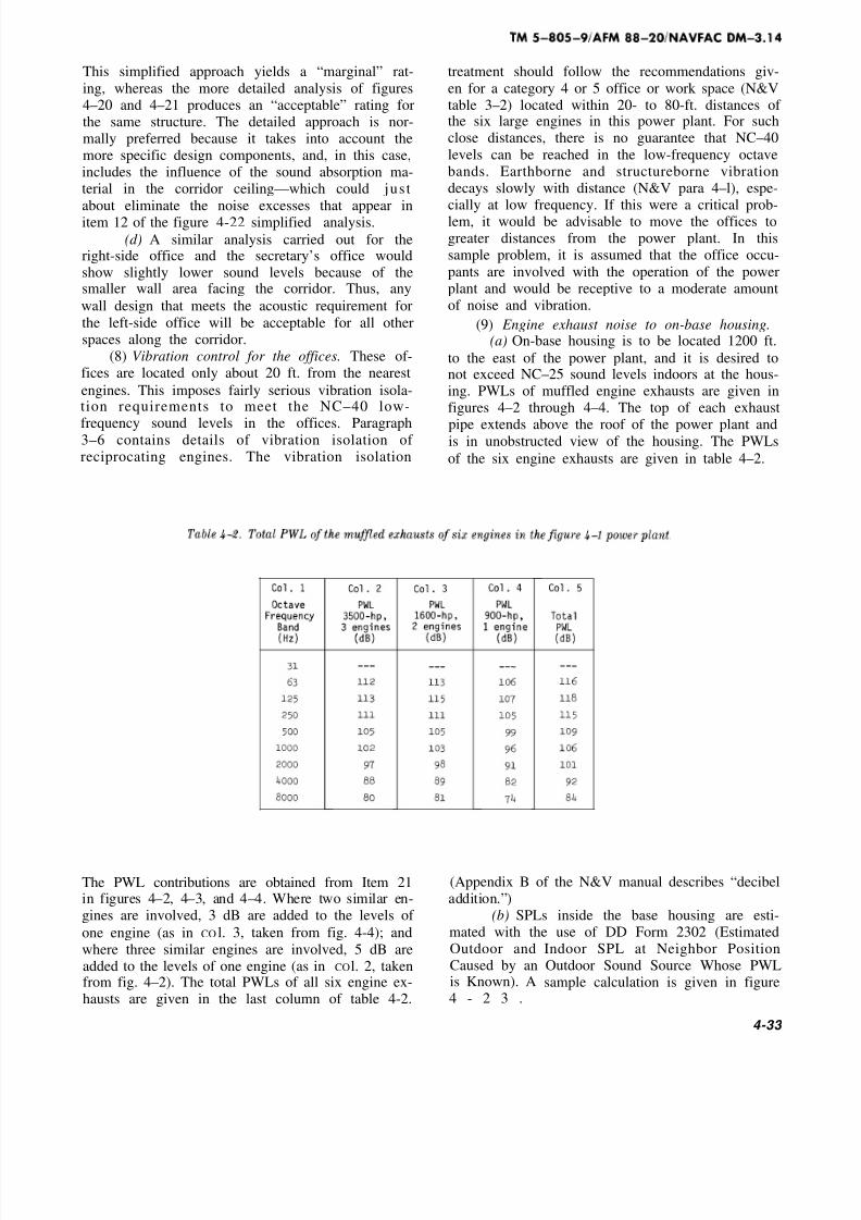
8/8/2019 Power Plant Acoustics-b
http://slidepdf.com/reader/full/power-plant-acoustics-b 71/96
This simplified approach yields a “marginal” rat-
ing, whereas the more detailed analysis of figures4–20 and 4–21 produces an “acceptable” rating forthe same structure. The detailed approach is nor-mally preferred because it takes into account themore specific design components, and, in this case,includes the influence of the sound absorption ma-terial in the corridor ceiling—which could just
about eliminate the noise excesses that appear initem 12 of the figure 4-22 simplified analysis.
(d) A similar analysis carried out for theright-side office and the secretary’s office wouldshow slightly lower sound levels because of thesmaller wall area facing the corridor. Thus, any
wall design that meets the acoustic requirement for
the left-side office will be acceptable for all otherspaces along the corridor.
(8) Vibration control for the offices. These of-fices are located only about 20 ft. from the nearest
engines. This imposes fairly serious vibration isola-tion requirements to meet the NC–40 low-
frequency sound levels in the offices. Paragraph3–6 contains details of vibration isolation of reciprocating engines. The vibration isolation
treatment should follow the recommendations giv-
en for a category 4 or 5 office or work space (N&Vtable 3–2) located within 20- to 80-ft. distances of the six large engines in this power plant. For suchclose distances, there is no guarantee that NC–40
levels can be reached in the low-frequency octavebands. Earthborne and structureborne vibrationdecays slowly with distance (N&V para 4–l), espe-cially at low frequency. If this were a critical prob-lem, it would be advisable to move the offices togreater distances from the power plant. In thissample problem, it is assumed that the office occu-
pants are involved with the operation of the powerplant and would be receptive to a moderate amountof noise and vibration.
(9) Engine exhaust noise to on-base housing.(a) On-base housing is to be located 1200 ft.
to the east of the power plant, and it is desired tonot exceed NC–25 sound levels indoors at the hous-ing. PWLs of muffled engine exhausts are given infigures 4–2 through 4–4. The top of each exhaust
pipe extends above the roof of the power plant andis in unobstructed view of the housing. The PWLs
of the six engine exhausts are given in table 4–2.
The PWL contributions are obtained from Item 21 (Appendix B of the N&V manual describes “decibelin figures 4–2, 4–3, and 4–4. Where two similar en- addition.”)gines are involved, 3 dB are added to the levels of (b) SPLs inside the base housing are esti-
one engine (as in CO l. 3, taken from fig. 4-4); and mated with the use of DD Form 2302 (Estimated
where three similar engines are involved, 5 dB are Outdoor and
added to the levels of one engine (as in COl. 2, taken Caused by anfrom fig. 4–2). The total PWLs of all six engine ex- is Known). A
hausts are given in the last column of table 4-2. 4 - 2 3 .
Indoor SPL at Neighbor PositionOutdoor Sound Source Whose PWLsample calculation is given in figure
4-33

8/8/2019 Power Plant Acoustics-b
http://slidepdf.com/reader/full/power-plant-acoustics-b 72/96

8/8/2019 Power Plant Acoustics-b
http://slidepdf.com/reader/full/power-plant-acoustics-b 73/96
Item 13 shows an indoor noise excess of 3 to 6 dB in
the 125- to 1000-HZ octave bands. This would berated as “marginal”. If the NC–25 criterion is a
justified choice, these noise excesses should not bepermitted. A number of other factors could influ-
ence the decision. If the housing is exposed toother uncontrollable excess noise (such as nearby
highway activity or base aircraft activity), power
plant noise might not appear so noticeable. How-ever, if the base is located in a very quiet suburban
or rural area, with very little other noise, the pow-
er plant noise will be very noticeable. If the base islocated in a very hot or very cold region, year-round, and the windows are kept closed most of thetime, and if inside sources, such as air conditionersor central heating and cooling systems, are in near-
ly continuous use, external noise sources will not
be as noisy when heard indoors. These various con-ditions could be used to support or justify adjust-ments to the NC criterion. In the present problem,
it is assumed that such factors have already beenconsidered, and the NC–25 selection is a valid
choice.
(c) A CNR analysis should be carried out as
a means of checking or confirming the expected re-action of the housed personnel to the power plantnoise. The N&V manual (para. 3–3c) summarizes
the procedure. Figure 4–24 shows the CNR gridupon which the outdoor power plant SPLs areplotted (taken from Item 8 of fig. 4–23). A noise
level rank of “e” is obtained.
4-35

8/8/2019 Power Plant Acoustics-b
http://slidepdf.com/reader/full/power-plant-acoustics-b 74/96

8/8/2019 Power Plant Acoustics-b
http://slidepdf.com/reader/full/power-plant-acoustics-b 75/96
The N&V table 3–4 or figure 3–4 provides a meansof determining the correction number for the back-ground noise in the area. If background noise
measurements can be made at the existing base,
N&V figure 3–4 should be used; otherwise thebackground noise correction may be estimated by
selecting the most nearly applicable conditions of
N&V table 3–4. For this sample problem, a back-ground noise correction of +1 is used. N&V table
3–5 is then used to determine other correctionnumbers applicable to the problem. The followingcorrections are here assumed:
Correction for temporal or seasonal factorsDay and night o
Summer and winter o
“On” full time o
Correction for character of noiseNo unusual sounds o
Correction for previous exposureSome previous exposure and good
community relations o
Background noise correction
From discussion above +1
Total corrections +1
The CNR (composite noise rating) is then e + 1 =F. The N&V figure 3–5 is used to estimate the ex-
pected community response, where base personnel
are assumed to be the equivalent of “average resi-
dents. ” A CNR value of F indicates a strong reac-tion against the noise for the conditions assumed
here. A noise reduction of about 10 dB would bring
the reaction down to “sporadic complaints, ” whichmight be considered a reasonable condition. CNR
values of C or D are often encountered in nonmili-
tary situations.
(d) On the basis of both indoor and outdoorpower plant noise at the base housing, the above
analyses strongly suggest the need for a 5- to10-dB reduction of noise, with principal emphasis
on noise control in the 125- to 1000-HZ frequency
range.
(e) Several possibilities exist for reductionof the excess noise. If the base has a large land
area and is not yet constructed, the power plant
and the housing area can be moved farther apart.An increase in distance from 1200 ft. to 2000 ft.
would give a 250-Hz noise reduction of 5 dB, and anincrease in distance to 3000 ft. would give a 250-Hz
noise reduction of 10 dB (from N&V table 6–4). Asone alternative, the base housing can be designed
and constructed to have higher TL walls and closed
windows facing the power plant. This would reduce
indoor SPLs but would not change the outdoorSPLs. If possible, other large buildings on the base
could be used to shield the housing area from the
power plant. Two feasible alternatives could be ap-plied at the power plant. In one, special large-
volume, low-pressure-drop mufflers could be used,either singly or in series, in the exhaust lines from
the engines to provide greater insertion loss than isquoted in table 3–2 for the rather conventionalgrades of mufflers. Such mufflers have been used
successfully with large engines located as close as600 to 800 ft. from residential areas. As another al-
ternative, an outdoor L-shaped barrier wall ex-
tending above the top of the exhaust pipe openingsfor the engines in Engine Room No. 1 could be
built above the second-floor Mechanical Equipment
Room and the south wall of the Engine Room to
give a beneficial amount of noise reduction for the
exhaust of the three 3500-hp engines. The exhaustmufflers for the two 1600-hp engines could be
specified and purchased to have a larger amount of insertion loss than assumed in the figure 4–4 analy-
sis. The 900-hp engine is the quietest one of the en-
tire group and may or may not need additionalmuffling, depending on the success of the other
pursuits.
(10) Other engine noise to on-base housing.(a) Turbocharger inlet noise for the three
outdoor inlets of the 3500-hp engines should bechecked for meeting the desired indoor and outdoor
levels of the base housing. The PWLs of the un-muffled inlet of one such engine is given in Item 16
of figure 4–2. These levels should be increased by 5
dB (for three engines), then extrapolated to the
1200-ft. distance. The inlet openings are partially
shielded by the power plant building, and the bar-rier effect of the building can be estimated. Ab-
sorbent duct lining in the air inlet ducts or dissipa-tive mufflers at the intake to the air cleaners can
be very effective at reducing the high-frequency
tonal sounds of the turbochargers.(b) Sound from Engine Room No. 2 can es-
cape from the open vent on the east wall of this
room and travel directly to the housing area. Fig-ure 4–23 shows the principal steps in the analysisof this part of the problem.
4-37

8/8/2019 Power Plant Acoustics-b
http://slidepdf.com/reader/full/power-plant-acoustics-b 76/96

8/8/2019 Power Plant Acoustics-b
http://slidepdf.com/reader/full/power-plant-acoustics-b 77/96
The SPLs inside Engine Room No. 2 are approxi-mately those shown in figure 4–12. The PWL of thenoise escaping through the unmuffled vent is calcu-lated from equation 7–18 of the N&V manual. Thisis given in Item 2 of figure 4–25, for the open vent
area of 40 ft.2
. A 3-ft.-long low-pressure-drop dissi-pative muffler (data from table 3–10) is firstplanned for the vent opening (Item 6 in fig. 4-25).
The noise radiating from the open front of the muf-fler has a small amount of directivity increase to-ward the housing. If the opening could freely radi-ate its sound in all horizontal directions, there
would be no special directional effect, and normalsound propagation would exist. However, thepresence of the large-area east wall of the buildingacts as a baffle that keeps one-half of the soundfrom radiating to the west. Thus, the sound thatwould have gone to the west (if the building were
doubles the PWL of the sound radiating to the eastand a 3-dB increase is added at Item 7. Combiningall the factors, Item 13 of the analysis shows thatthe vent will produce 2-dB excess indoor levels atthe housing in the 500-Hz band. When added to all
other noise coming from the power plant, the totalexcess could be even larger. Thus, a better designwould be either a 5-ft.-long low-pressure-drop muf-
fler or a 3-ft.-long high-pressure-drop muffler orsome other acceptable combination available from amuffler supplier.
(c) Next, noise radiated from the exterioreast wall of the building should be checked. Materi-al from paragraph 3–2a and equation 3–3 are in-volved (LW = LP – TL + 10 log A–16). Figure 4-26summarizes the calculations of the PWL of thenoise radiated externally by the east wall of En-
n ot there), instead is reflected to the east. This gine Room No. 2.
Column 2 gives the SPL inside the Engine Room, graph 3–2a, it should be determined that this cal-as taken from figure 4–12. Column 3 gives the TL
of the exterior wall of the building, 10-in. -thick hollow-core concrete block, from N&V table 5-9.
Column 4 represents the term (10 log A–16), wherethe area of the east wall is 30 x 4 0 = 1 2 0 0 ft.
2
when the 40-ft.2
area of the muffled vent opening isneglected). Column 5 is then the radiated PWL of equation 3–3 (Column 5 = Column 2 – Column 3 +Column 4). In accordance with the caution of para-
culated radiated PWL does not exceed the low-frequency PWL of the sources inside the room.
This is done by comparing the Column 5 valueswith the sum of the engine casing PWLs of the
three engines in Engine Room No. 2 (from fig. 4–3and 4–4). This sum is shown in Column 6. It is clearthat the Column 5 values are less than the Column6 values. The Column 5 PWL is next extrapolatedto the base housing with the use of figure 4–27.
4-39

8/8/2019 Power Plant Acoustics-b
http://slidepdf.com/reader/full/power-plant-acoustics-b 78/96
8/8/2019 Power Plant Acoustics-b
http://slidepdf.com/reader/full/power-plant-acoustics-b 79/96
Comparison of the SPLs in Items 10 and 12 showsthat the noise radiated by the wall will fall about 20to 30 dB below the NC–25 indoor criterion levels.Thus, wall-radiated noise will be of no concern in
this sample problem.
(d) Engine noise escaping through the roomshould be checked in accordance with paragraph
3–2d. The roof deck for the building is of 2-in. -
thick poured concrete on corrugated metal. The TLof the roof deck is estimated to be about the same
as that of 2-in. -thick dense plaster (N&V table5–11) or about 4 dB less than that of 4-in. -thick
dense plaster (N&V table 5–ll) or about 5dB less
than that of 4-in.-thick dense concrete (N&V table5–8), whichever is less. Equation 3–3 is used hereto obtain the PWL radiated separately by each En-gine Room roof. Then, the directivity loss in the
horizontal direction is applied, using table 3-1. The
power plant building has a parapet, so it qualifiesas a Type 1 roof, and the smaller D dimension of
each Engine Room is 40 ft., so the column of
directivity corrections for “D under 50 ft. ” shouldbe used. Each Engine Room has different soundsources, so the effect of each roof section must be
calculated. Only one roof (for Engine Room No. 2)is illustrated in figure 4–28.
4-41

8/8/2019 Power Plant Acoustics-b
http://slidepdf.com/reader/full/power-plant-acoustics-b 80/96

8/8/2019 Power Plant Acoustics-b
http://slidepdf.com/reader/full/power-plant-acoustics-b 81/96
Item 2 in the figure is the PWL of roof-radiated
noise obtained with the use of equation 3–3, usingthe TL of 2-in. dense plaster and an area of 40 x 5 0
= 2000 ft.2
Comparison of Items 10 and 12 shows
that roof-radiated noise is also about 20 to 30 dBbelow NC–25 indoor sound levels at the base
housing.(e) This completes the basic analysis of the
community noise obtained from each noise source
of group of noise sources considered in this samplecalculation. One final check is required of the en-tire plant. When the analysis is completed on eachindividual source radiating toward the housing, and
suitable noise control measures are tentatively se-lected for each source, a final analysis should be
made of the entire plant. All sources together mustnot exceed the noise criterion in all octave bands.
If a few sources combine to produce excessivenoise in one or more octave bands, the noise con-
trol treatments for those sources in those octave
bands should be improved sufficiently to eliminate
the calculated noise excess completely. This final
step in the total analysis should assure a satisfacto-ry noise design for the complete installation.
4-3. Example of an on-grade packaged gas
turbine generator plant.
The gas turbine generator plant plays an increas-ingly prominent role in out-of-the-way locations forboth continuous and peak-load applications. Its rel-
ative portability means that it can be moved in andset up almost anywhere power is needed, but, by
the same token, its light weight makes it a poten-tial noise problem. The gas turbine is basically avery noisy device, and the simple cabinet-like en-
closure and the all-too-frequent shortage of ade-
quate mufflers do not always control the noise.a. Description of power plant. In this example, a
15-MW plant is supplied by the manufacturer in a
packaged form as shown in figure 4–29.

8/8/2019 Power Plant Acoustics-b
http://slidepdf.com/reader/full/power-plant-acoustics-b 82/96
This plant is to be located 1600 ft. from a militarybase hospital, and it is the designer’s responsibility
to specify the acoustic requirements of the pack-aged generator. The gas turbine power outputshaft, operating at 7200 rpm, drives a gear whichin turn drives a generator at 3600 rpm. The Engine
Room and the Generator Room are ventilated by
30-hp fans, as seen in the exhaust vents of these
two rooms in figure 4–3. The manufacturer pro-vides a housing for the entire unit that is made of l/16-in. -thick sheet steel with a 4-in .-thick absorb-
ent lining on the inside, covered with 22-gauge per-forated sheet steel. Consideration should be givento the following parts of the noise problem: Muffler
requirement and design for the air inlet to the en-gine, muffler requirement and design for the en-
gine exhaust, noise escape from the walls and roof
of the entire package, noise escape from the venti-lation openings of the Engine and GeneratorRooms, hearing protection for operators, whennecessary, and acceptable noise levels in the Con-
trol Room. In this sample problem, only the intakeand exhaust muffler requirements are evaluated.Details of the other parts of the total study wouldfollow along the lines of the example given in detail
in paragraph 4–2.
b. PWL criterion for noise to hospital. It is firstrequired to estimate the total PWL of the power
plant that will just produce acceptable sound levelsinside the hospital building at a distance of 1600-ft.An indoor criterion of NC–20 for patient rooms is
wanted. This low level is selected to help reduce
the audibility of the tonal sounds of the plant. Thehospital is fitted with sealed-closed windows, with
each room receiving some fresh air through smallwall vents to the outside (similar to wall type C in
the N&V table 6–10). There is a tall growth of me-dium dense woods between the power plant and thehospital. The woods are about 500 ft. deep, and thetrees are about 40 ft. high. The top of the exhaust
stack of the power plant is about 30 ft. above ground
elevation, and the upper windows of the two-floorhospital buildings are about 25 ft. above ground.
The approximate insertion loss of the woods is esti-mated with the use of DD Form 2300 (Elevation
Profile Between Sound Source and Receiver Posi-tion) and DD Form 2301 (Estimation of Insertion
Loss of Vegetation in Outdoor Sound Path). Fig-ures 4–30 and 4–31 are filled-in copies of these two
data forms.
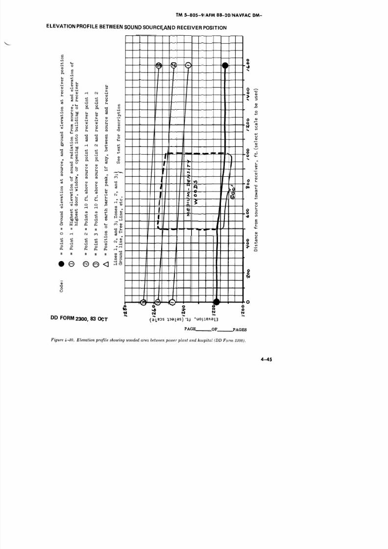
8/8/2019 Power Plant Acoustics-b
http://slidepdf.com/reader/full/power-plant-acoustics-b 83/96

8/8/2019 Power Plant Acoustics-b
http://slidepdf.com/reader/full/power-plant-acoustics-b 84/96

8/8/2019 Power Plant Acoustics-b
http://slidepdf.com/reader/full/power-plant-acoustics-b 85/96
The PWL criterion for the total power plant noise verse order, shows the steps in this calculation.
can now be calculated. DD Form 2302, used in re- This is illustrated in figure 4–32.

8/8/2019 Power Plant Acoustics-b
http://slidepdf.com/reader/full/power-plant-acoustics-b 86/96

8/8/2019 Power Plant Acoustics-b
http://slidepdf.com/reader/full/power-plant-acoustics-b 87/96
1.
2.

8/8/2019 Power Plant Acoustics-b
http://slidepdf.com/reader/full/power-plant-acoustics-b 88/96
The engine is housed inside the enclosure of the en-
tire engine-generator package, which is assumed tohave approximately the noise reduction of the type
5 enclosure of table 2–7. Both the air intake andexhaust stacks are oriented vertically and have the
horizontal directivity effect shown for the 90° anglein table 2–8. Each stack will be fitted with a muf-fler, whose insertion loss is still to be determined,
but the muffler and the 90° turn into the enginewill provide at least a Class 1 lined bend (fig. 3–1
and table 3–9). If a longer muffler (greater inlength than 1.5D in fig. 3–1) is later found necessa-
ry, this turn may qualify as a Class 2 lined bend,
with a slight improvement in insertion loss. Thetentative PWLs of the three sources are given inItems 6, 13, and 20 of figure 4–33, without the in-
sertion losses of the intake and exhaust mufflers.In table 4–3, these three PWLs are added together
and compared with the PWL criterion developed infigure 4-32.
The last column in table 4–3 shows the amount of the 2000- and 4000-Hz bands, and the engine casingnoise reduction required for the total plant to meet
the criterion PWL. If in any given octave band allthree engine components contribute significantly tothe total noise, some of the sources must be qui-
eted more than the column 7 amount, so that thetotal of the three components does not exceed the
column 6 criterion. This point is illustrated by look-
ing at the 500-Hz values, for example. If eachsource alone is quieted to just meet the 112-dB cri-terion value, the total of the three quieted compo-
nents would be 117 dB, or 5 dB above the criterionlevel. Thus, the three sources must be quieted to
such an extent that their new total (“decibel sum”)
will just equal 112 dB. From table 4–3, it is seenthat the engine exhaust is clearly the dominant
source in the 31- through 500-Hz octave bands, theengine intake noise exceeds the exhaust noise in
noise is fairly close to the PWL criterion in the 250-
through 2000-Hz bands. This implies that all threesources may have to be quieted for the entire plant
to meet the criterion.
d. Mufflers for engine intake and exhaust.
(1) Table 4-3 shows that the engine exhaust
will require a muffler that should have insertionloss values of at least 2 dB at 63 Hz, 10 dB at 125Hz, and 11 dB at 250 and 500 Hz, at an elevated ex-
muffler should have insertion loss values of about 2
or 3 dB at 125 Hz, about 3 to 5 dB at 250 Hz, andabout 5 to 10 dB in each of the 500- through2000-Hz bands. Tables 3–3 through 3–8 may be
used to approximate the dimensions of mufflers
4-50

8/8/2019 Power Plant Acoustics-b
http://slidepdf.com/reader/full/power-plant-acoustics-b 89/96
exhaust temperature, the speed of sound would beabout 1870 ft./see (from equation 2–1 in the N&Vmanual), which is about 1.7 times the speed of
sound in air at normal temperature, assuming theexhaust gases are made up largely of the normal
contents of air. This means that the exhaust muf-
fler should be about 1.7 times longer than it wouldhave to be at normal temperature to produce the
same insertion loss.(2) Table 3-6 offers a reasonable design for theexhaust muffler: 8-in. -thick parallel baffles sepa-
rated by 8-in. -wide air spaces. The 8-ft. length ex-
ceeds the insertion loss requirement in all the oc-tave bands, but by only 1 dB in the 125-Hz band. A
7-ft. length (at normal temperature) would verynearly meet the 10-dB requirement at 125 Hz. For
the elevated temperature, the length should be in-
creased to about 12 ft.: (7 x 1.7 approximately).
The cross-section area of the exhaust muffler mustbe large enough not to generate excessive back
pressure and muffler self-noise.
(3) Table 3-3 offers a reasonable design for theintake muffler: 4-in. -thick parallel baffles sepa-
rated by 12-in. -wide air spaces. An 8-ft. length of such design will meet the desired insertion loss
values in all bands. This length will help the intake
stack qualify as a class 1 lined band (a 4-ft.-lengthmuffler would not be long enough; fig. 3–l); andthe relatively large percent of open area will mini-
mize inlet pressure drop.
(4) Table 4-4 summarizes the sound power lev-
els of the three engine components with these muf-flers installed. Comparison of the inlet and exhaust
PWLs of tables 4–3 and 4–4 (co1. 3 and 4) shows theamount of insertion loss assumed for the mufflers.
A l-dB excess of noise still appears in the 125-Hz
band, but the total design appears well balancedover the 63- through 2000-Hz bands.
(5) The insertion loss values used in this studyand given in the chapter 3 tables are intended forinformation and guidance only. As stated in para-graph 3–4a, muffler manufacturers should be
consulted on the design and performance of their,.-
were listed, wheras only the inlet and exhaust muf-flers have been evaluated here. In a total study,
the SPL inside the Engine Room should be esti-mated (Room Constant and engine casing PWL are
required), and the PWL radiated by the externalshell of the housing should be calculated (as in
para. 3–2). In the muffler analysis above, the noisereduction of the housing was merely estimatedfrom its similarity with the type 5 enclosure of ta-
mufflers. ble 2-7. The noise of the gear and generator in thee. Other aspects of this sample problem. In a Generator Room should also be estimated (from
above, several parts of the total noise problem chap. 7 tables in the N&V manual), and the noise
4 - 5 1
8/8/2019 Power Plant Acoustics-b
http://slidepdf.com/reader/full/power-plant-acoustics-b 90/96
escaping outside and through the two walls to theControl Room should be evaluated and comparedwith the applicable criteria. For both the Engine
Room and the Generator Room, the escaping noisethrough the ventilation openings should be checked
(including the noise of the 30-hp fans), and the in-sertion losses of the wall- and roof-mounted muf-flers estimated. The total noise from all sources
must be kept at or below the PWL criterion evalu-ated in figure 4–32. The external side walls of theintake and exhaust stack must have adequate TL(transmission loss) so that noise does not escape
through these side-wall flanking paths. The TL of the side walls should be at least 10 dB greater thanthe insertion loss of the muffler (para. 3–4a).
Finally, for conservation of hearing, personnelshould be admitted into the Engine Room and Gen-erator Room only when wearing adequate hearing
protection, possibly consisting of both ear plugsand ear muffs. SPLs inside the Engine Room mayexceed 110 to 115 dB in the upper octave bands if
the engines do not have noise-reducing covers.Suitable labeling of the noise-hazardous areasshould be included in the design of the plant.
4-4. Summary and conclusions.
a. The specific examples illustrated in this chap-
ter and the generalized applications given in theN&V manual show the various calculable steps in-
volved in the analysis of a wide variety of noiseproblems and solutions. Some of the acoustic analy-ses are quite simple and straightforward, and theresults are quite reliable. However, some of the
analyses involve approximations and a few nonrig-
orous steps, and a few of these are included in theexample—largely to demonstrate that such ap-
proaches must sometimes be taken when exactnessis not possible.
b. Data forms are used freely throughout thisand the N&V manual to show that they are simpleto use, that they remind the user of many key
steps in the calculation procedures, that they pro-vide documentation of the rationale and data usedto arrive at acoustic designs, and that they are suf-
ficiently flexible to be adapted to slightly differentconditions from those for which they were de-signed. Blank copies of the data forms developed
for this and the N&V manual are reproduced in ap-
pendix A. These forms may be duplicated and usedto analyze and document the various steps inacoustic designs covered by these manuals.
c. A dilemma that might be brought on by themanual is the impasse which could develop whenmanufacturers state that their equipment or sound
control devices perform better acoustically than is
assumed here. If this situation should arise, it isimportant to receive some form of guaranteed as-
surance in writing (accompanied by valid test datacarried out by a reputable and disinterested organ-ization) that the manufacturer will back up the
claims.
d. The procedures used in these manuals haveevolved over the past 20 to 30 years of applied
acoustics in the United States and have been usedsuccessfully to evaluate and solve many types of noise problems. The data and procedures are rec-ommended for use by engineers, architects, and
planners of military installations as well.
4–52

8/8/2019 Power Plant Acoustics-b
http://slidepdf.com/reader/full/power-plant-acoustics-b 91/96
APPENDIX A
DATA FORMS
A blank copy of each of the data forms prescribed in this manual (DD Forms
2304 and 2305) can be located in appendix A. For Army, DD Forms 2304 and2305 will be reproduced locally on 8 1/2 inch by 11 inch paper. Copies to be ex-
tracted for local reproduction are located in appendix A of this regulation.For Navy and Air Force, copies are available through normal forms/publica-tions supply channels. Appendix E, TM 5–805–4/AFM 88–37/NAVFACDM-3.10 contains blank forms for DD Forms 2294 through 2303.

8/8/2019 Power Plant Acoustics-b
http://slidepdf.com/reader/full/power-plant-acoustics-b 92/96

8/8/2019 Power Plant Acoustics-b
http://slidepdf.com/reader/full/power-plant-acoustics-b 93/96

8/8/2019 Power Plant Acoustics-b
http://slidepdf.com/reader/full/power-plant-acoustics-b 94/96
TM 5-805-9/AFM 88-20/NAVFAC DM-3.14
APPENDIX B
REFERENCES
Governmen t Pub l i ca t i ons
Depa r tmen t o f De fense
Del) 6 0 55 . 3 Hearing Conservation.
Department of the Army
TM 5-805-4 Noise and Vibration Control forMechanical Equipment.
Non-Gove rnmen t Pub l i ca t i on
American Society of Heating, Refrigeration and Air Conditioning
Engineers, Inc. (ASHRAE), 347 East 47th Street, New York, NY10017.
Handbook and Product Directory, Fundamentals. (1977)
B-1

8/8/2019 Power Plant Acoustics-b
http://slidepdf.com/reader/full/power-plant-acoustics-b 95/96
APPENDIX C
BIBLIOGRAPHY
AFM 19–10 Planning in the Noise Environment. Naval Publications and
Forms Center, 5801 Tabor Ave., Philadelphia, PA 19120.
AFR 161-35 Hazardous Noise Exposure, HQ. U.S.A.F. WASH, DC 20330.
AR 40-5 Medical Services, Health and Environment, U.S. Army A. G. Pub-
lications Center, 1655 Woodson Rd., St. Louis, MO 63114
BUMEDINST 6260.6B Hearing Conservation Program, U.S. Army A. G.Publications Center, 1655 Woodson Rd., St. Louis, MO 63114
DoD 4270. 1–M Department of Defense Construction Criteria, Supt. of Docu-
ments, U.S. G.P.O. WASH, DC 20402
DoD Instruction 6055.1 Department of Defense Occupational Safety and
ER
ER
Health Program.
1110–345–100 Engineering and Design, Design Policy for Military Con-
struction. USACE Publications Depot, 890 South Pickett St., Alex-andria, VA 22304.
11 10–345–700 Engineering and Design, Design and Analysis. USACE
Publications Depot, 890 South Pickett St., Alexandria, VA 22304.
NAVFAC DM–1 Design Manual, Architecture. Naval Publications andForms Center, 5801 Tabor Ave., Philadelphia, PA 19120.
NAVFAC DM–3 Design Manual, Mechanical Engineering. Naval Publica-tions and Forms Center, 5801 Tabor Ave., Philadelphia, PA 19120.
TB MED 501 Occupational & Environmental Health: Hearing Conserva-
tion. U.S. Army A. G. Publications Center, 2800 Eastern Blvd., Balti-
more, MD 21220.
TM 5–800–1 Construction Criteria for Army Facilities, U.S. Army A. G.Publications Center, 1655 Woodson Rd., St. Louis, MO 63114.
TM 5–838–2 Army Health Facility Design, U.S. Army A. G. PublicationsCenter, 1655 Woodson Rd., St. Louis, MO 63114.
Beranek, Leo L., Noise Reduction. McGraw-Hill, New York, NY 1960.
Harris, Cyril M., Handbook of Noise Control. McGraw-Hill, New York, NY
1979.
Miller, J. D., “Effect of Noise on People,” Journal of the Acoustical Society
of America. Vol. 56, No. 3, 1974.
Environmental Protection Agency 550/9–74–00 Information on Levels of En-vironmental Noise Requisite to Protect Public Health and Welfare with
an Adequate Margin of Safety, 1974. Superintendent of Documents,U.S. G. P. O., WASH, DC 20402.
IS0, Assessment of Noise with Respect to Community Response,
ISO/R1996–1971, 1971.1, Rue de Varembe, case postale 56, Geneva, 20,
Switzerland.
C-1

8/8/2019 Power Plant Acoustics-b
http://slidepdf.com/reader/full/power-plant-acoustics-b 96/96
TM 5-805-9/AFM 88–20/NAVFAC DM-3.14
The proponent agency of this publication is the Office of the Chief of En-
gineers, United States Army. Users a re inv i ted to send comments and
suggested improvements on DA Form 2028 (Recommended Changes to
Publications and Blank Forms) direct to HQDA (DAEN-ECE-E), WASH,
DC 20314.
By Order of the Secretaries of the Army, the Air Force, and the Navy:
Official:
ROBERT M. JOYCE Major General, United States
The Adjutant General
Official:
JAMES H. DELANEYColonel, United States Air Force
Director of Administration
JOHN A. WICKHAM, JR.General, United States Army
Chief of Staff
Army
CHARLES A. GABRIELGeneral, United States Air Force
Chief of Staff
W. M. ZOBEL Rear Admiral, CEC, United States Navy
Commander, Naval Facilities Engineering Command
DISTRIBUTION:
Army: To be distributed in accordance with DA Form 12–34B, requirements for TM 5–800 Series: En-gineering and Design for Real Property Facilities
Air Force: F
Navy: Special distribution list.