Embed Size (px)
Citation preview

Power Plant Model Validation and Performance Monitoring
Dmitry Kosterev, Steve Yang, Pavel
Etingov
NASPI Workshop
October 2103
Power System Models
•
Accurate power system models are required for reliable
and economic
power grid operations
•
Failure of models to predict
system behavior
•
7.4M customers lost power
due to the outage
•
Major interties were de‐
rated temporarily by 33%
•
WSCC BOT required all
generators >20 MVA be
tested for model validation
4000
4200
4400
4600
0 10 20 30 40 50 60 70 80 90
4000
4200
4400
4600
Time in Seconds
Simulated COI Power (initial WSCC base case)
Observed COI Power (Dittmer Control Center)
August 10, 1996
Power Plant Model Verification Requirements
•
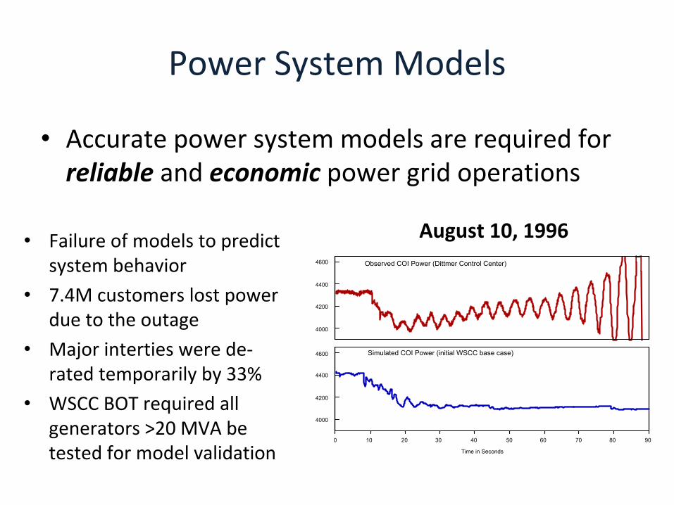
1996 –
generator baseline testing for model verification is
required in WSCC
–
Benefits of WECC generator testing program are
indisputable:•
Vast majority of models needed revisions
•
Structural model errors were detected
•
Errors in control settings were identified and corrected
–
Need to sustain the model validation was apparent
•
2006 – WECC formalized its Generating Unit Model
Validation Policy
•
Baseline Model Development
•
Periodic Model Validation
Reliability Standards
•
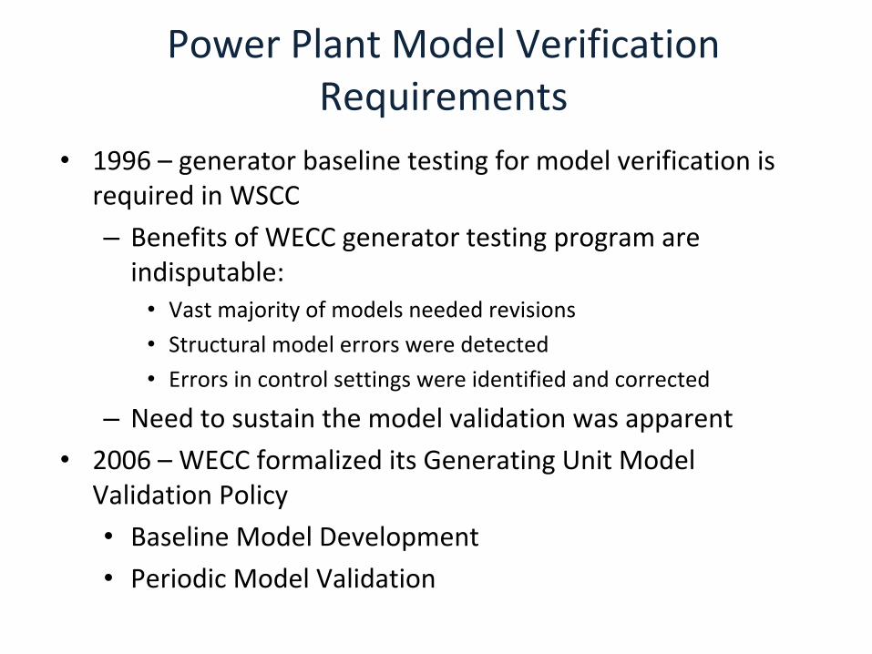
2007 – NERC started the development of model verification standards
•
2013 – NERC approved–
NERC MOD‐025 ‐
reactive power capabilities verification
–
NERC MOD‐026 – generator and excitation control model
verification–
NERC MOD‐027 – generator turbine control model
verification–
NERC PRC‐019 –
coordination of generator protection and
controls
•
2013 – NERC MOD‐B effort to address FERC directives
‐
Requires plant operator to provide accurate model data
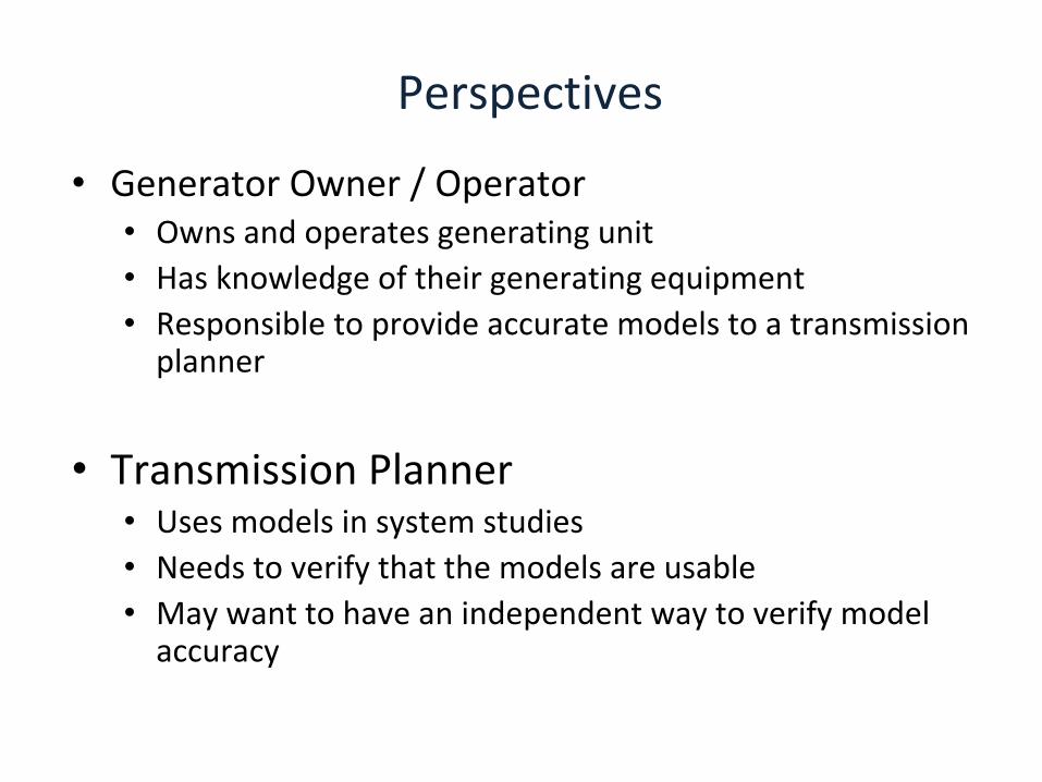
Perspectives
•
Generator Owner / Operator•
Owns and operates generating unit
•
Has knowledge of their generating equipment•
Responsible to provide accurate models to a transmission
planner
•
Transmission Planner•
Uses models in system studies
•
Needs to verify that the models are usable•
May want to have an independent way to verify model
accuracy

Generator Owner
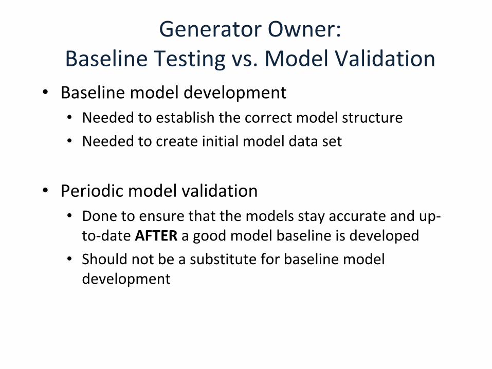
Generator Owner: Baseline Testing vs. Model Validation
•
Baseline model development•
Needed to establish the correct model structure
•
Needed to create initial model data set
•
Periodic model validation •
Done to ensure that the models stay accurate and up‐
to‐date AFTER a good model baseline is developed
•
Should not be a substitute for baseline model
development
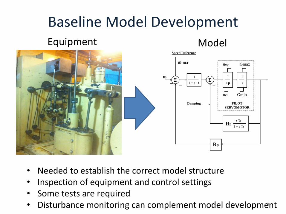
Baseline Model Development
8
Equipment Model
Rp
REF
s Tr
1 + s TrRt
Speed Reference
1
s
Gmax
Gmin
uop
ucl
PILOTSERVOMOTOR
1
1 + s Tf
1 Tp
Damping
•
Needed to establish the correct model structure•
Inspection of equipment and control settings
•
Some tests are required•
Disturbance monitoring can complement model development

EASY
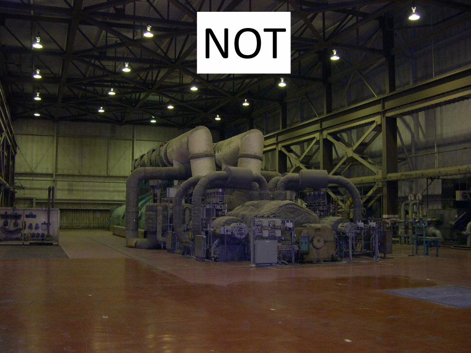
NOT
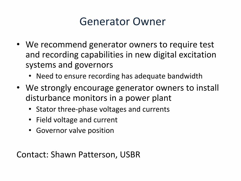
Generator Owner
•
We recommend generator owners to require test and recording capabilities in new digital excitation systems and governors
•
Need to ensure recording has adequate bandwidth
•
We strongly encourage generator owners to install disturbance monitors in a power plant
•
Stator three‐phase voltages and currents•
Field voltage and current
•
Governor valve position
Contact: Shawn Patterson, USBR

Transmission Planner
10 15 20 25 30 35 40 45 50 55 60150
155
160
165
170Active Power
Pow
er (M
W)
10 15 20 25 30 35 40 45 50 55 60-140
-120
-100
-80
-60Reactive Power
Pow
er (M
W)
Time (sec)
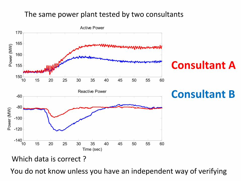
Consultant A
Consultant B
The same power plant tested by two consultants
Which data is correct ?
You do not know unless you have an independent way of verifying
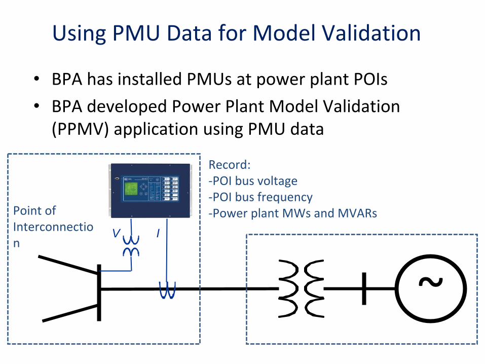
Using PMU Data for Model Validation
•
BPA has installed PMUs at power plant POIs
•
BPA developed Power Plant Model Validation (PPMV) application using PMU data
~
Record: ‐POI bus voltage‐POI bus frequency‐Power plant MWs and MVARsPoint of
Interconnectio
nV I
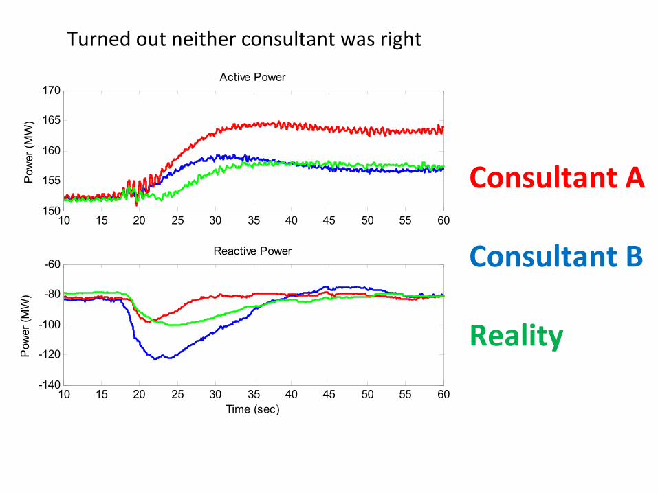
Consultant A
Consultant B
Reality
10 15 20 25 30 35 40 45 50 55 60150
155
160
165
170Active Power
Pow
er (M
W)
10 15 20 25 30 35 40 45 50 55 60-140
-120
-100
-80
-60Reactive Power
Pow
er (M
W)
Time (sec)
Turned out neither consultant was right
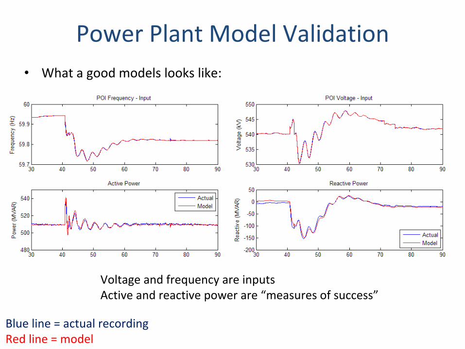
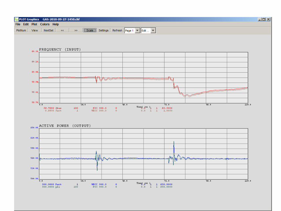
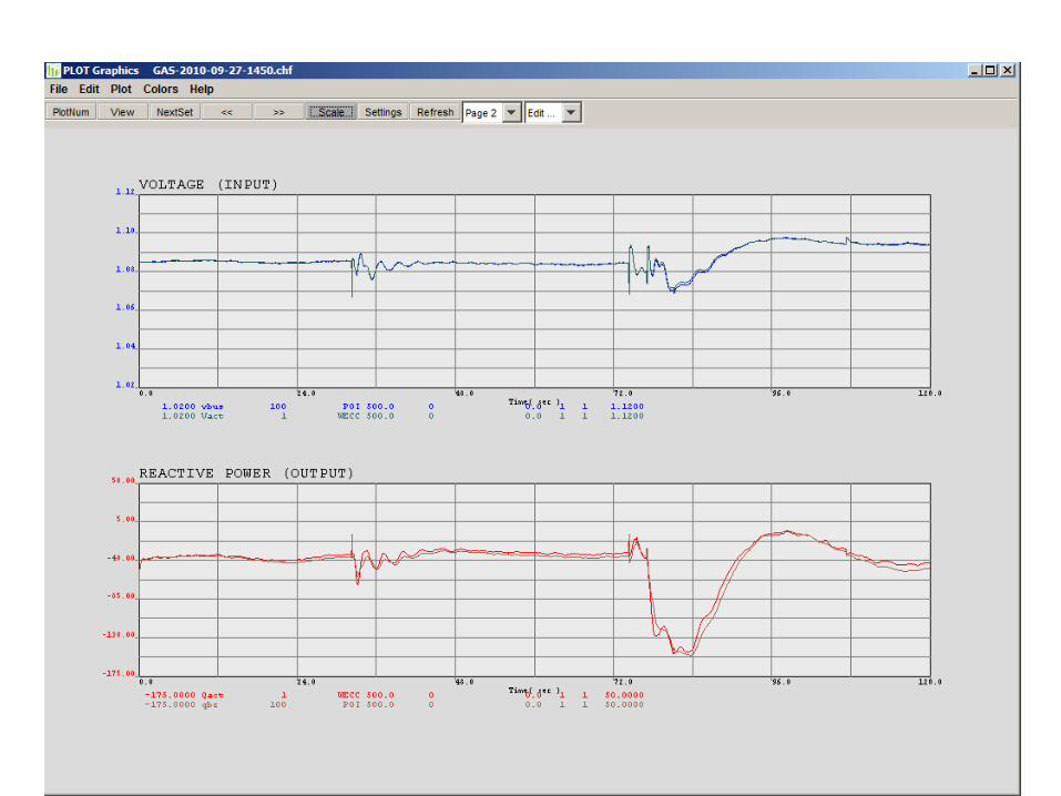
Power Plant Model Validation•
What a good models looks like:
Blue line = actual recordingRed line = model
Voltage and frequency are inputsActive and reactive power are “measures of success”
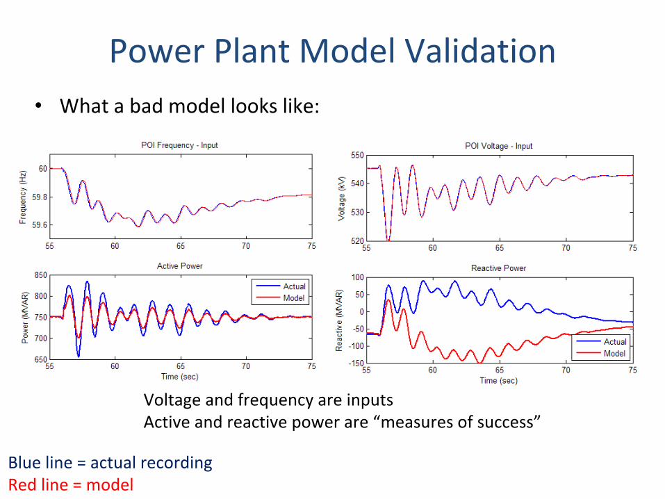
Power Plant Model Validation•
What a bad model looks like:
Blue line = actual recordingRed line = model
Voltage and frequency are inputsActive and reactive power are “measures of success”
BPA Experience with Disturbance‐Based Model Validation
•
Most common model issues:–
Power System Stabilizer models
–
Turbine control mode of operation / governor models–
Generator inertia
–
Deficiencies in model structure •
Other reasons for model mismatch–
Automatic Generation Controls
–
UEL •
“Clinical”
experience:
–
Plants with modern digital systems have good models that stay accurate over time
–
Plants with legacy analog controls have most errors and tend to change in time 18

Frequency Responsive PlantFrequency Responsive Plant
0 10 20 30 40 50 60 70 80 90 10059.7
59.8
59.9
60
60.1Frequency
Freq
uenc
y (H
z)
0 10 20 30 40 50 60 70 80 90 100310
320
330
340Power
Pow
er (M
W)
Time (sec)
Provides sustained frequency response
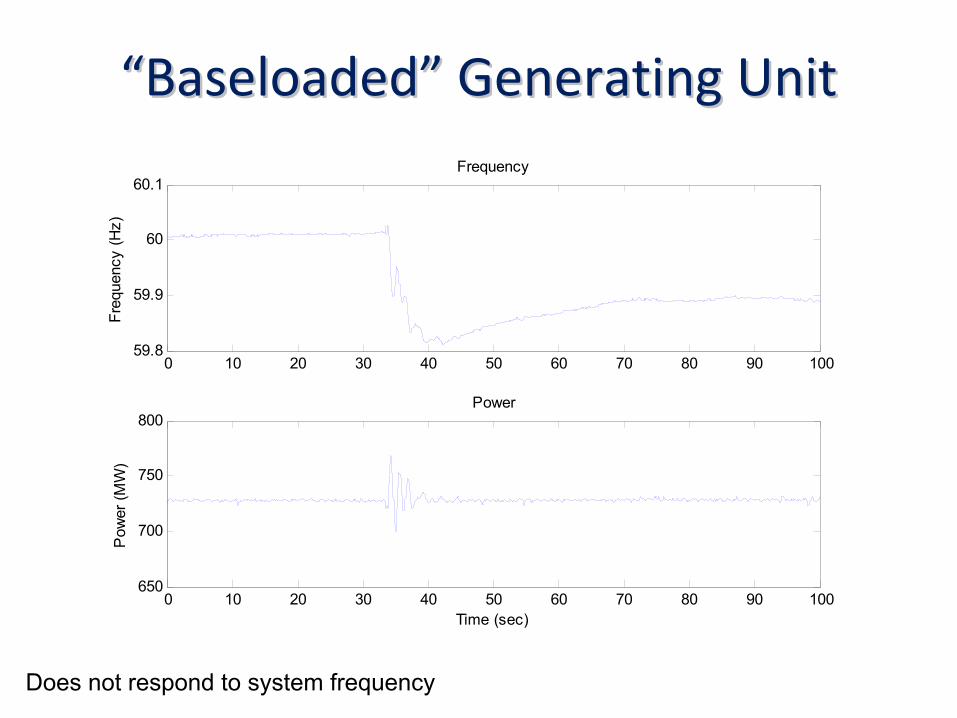
““BaseloadedBaseloaded””
Generating UnitGenerating Unit
0 10 20 30 40 50 60 70 80 90 10059.8
59.9
60
60.1Frequency
Freq
uenc
y (H
z)
0 10 20 30 40 50 60 70 80 90 100650
700
750
800Power
Pow
er (M
W)
Time (sec)
Does not respond to system frequency
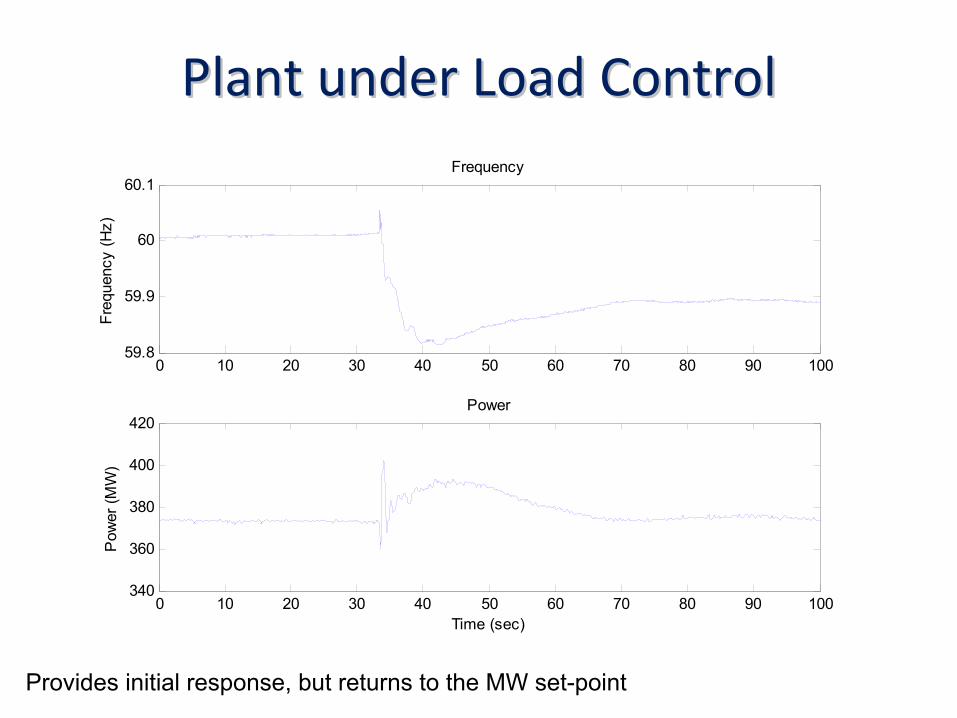
Plant under Load ControlPlant under Load Control
0 10 20 30 40 50 60 70 80 90 10059.8
59.9
60
60.1Frequency
Freq
uenc
y (H
z)
0 10 20 30 40 50 60 70 80 90 100340
360
380
400
420Power
Pow
er (M
W)
Time (sec)
Provides initial response, but returns to the MW set-point

Generator Performance Monitoring
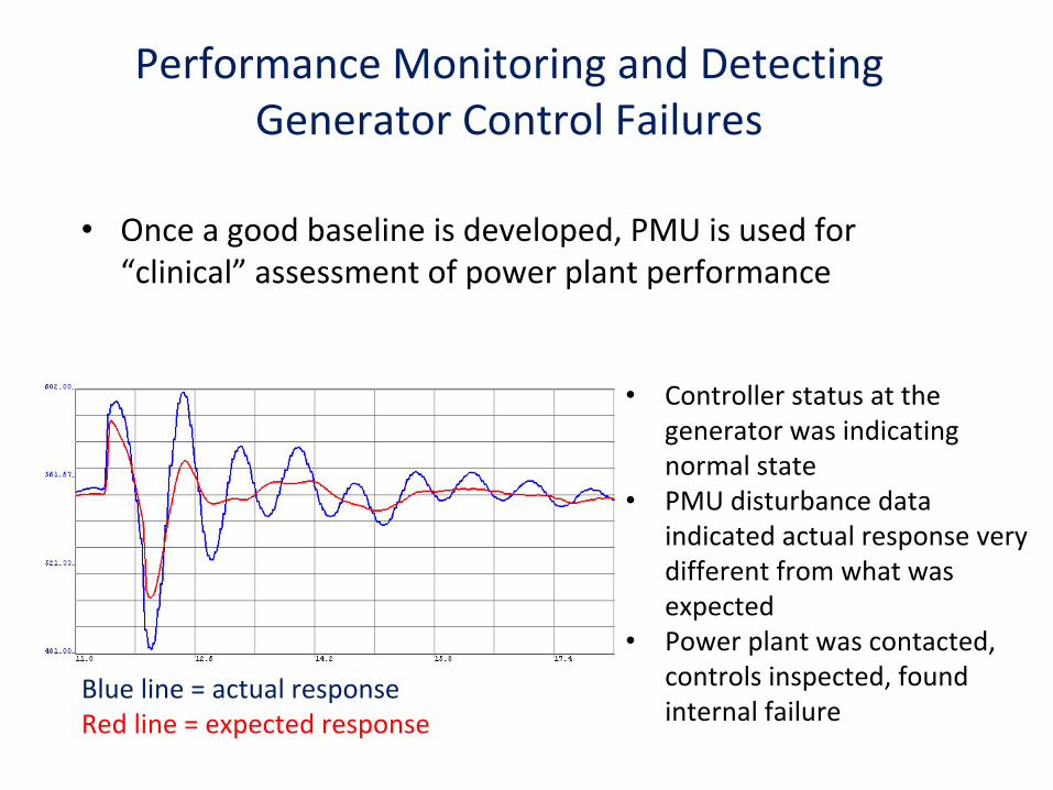
Performance Monitoring and Detecting Generator Control Failures
Blue line = actual responseRed line = expected response
•
Controller status at the
generator was indicating
normal state•
PMU disturbance data
indicated actual response very
different from what was
expected •
Power plant was contacted,
controls inspected, found
internal failure
•
Once a good baseline is developed, PMU is used for
“clinical”
assessment of power plant performance
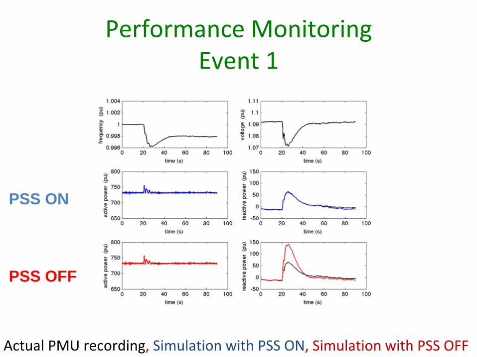
Performance Monitoring Event 1
PSS OFF
�PSS ON
Actual PMU recording, Simulation with PSS ON, Simulation with PSS OFF
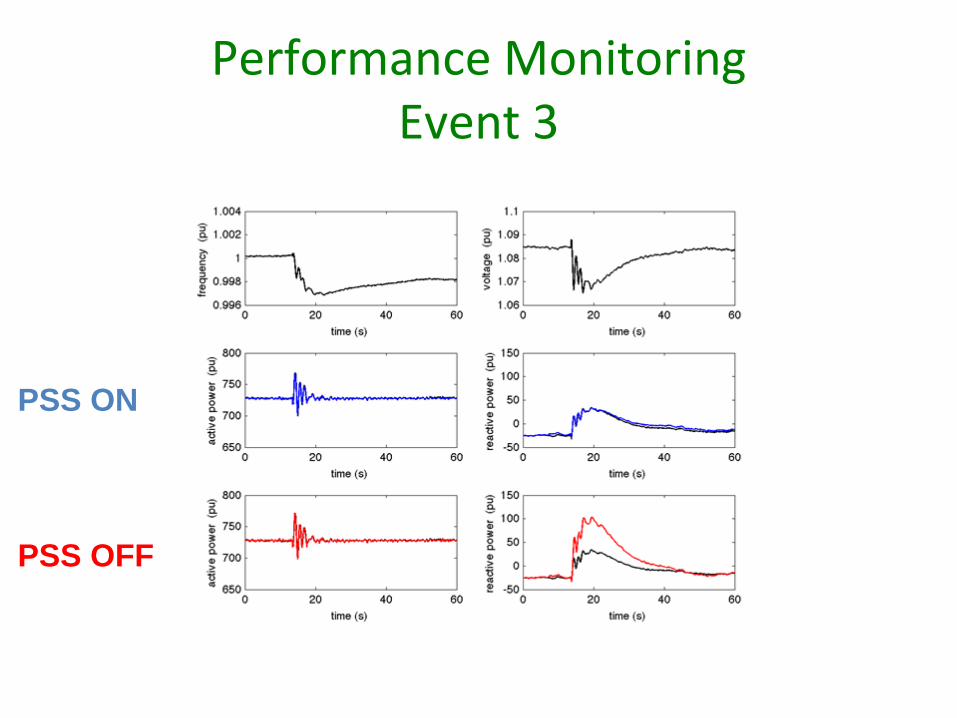
Performance Monitoring Event 3
PSS OFF
�PSS ON
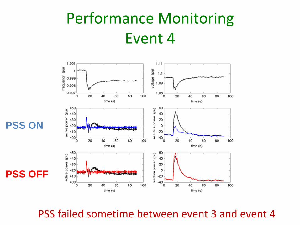
Performance Monitoring Event 4
PSS OFF
PSS ON
�
PSS failed sometime between event 3 and event 4
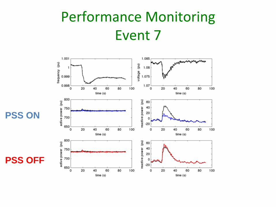
Performance Monitoring Event 7
PSS OFF
PSS ON
�
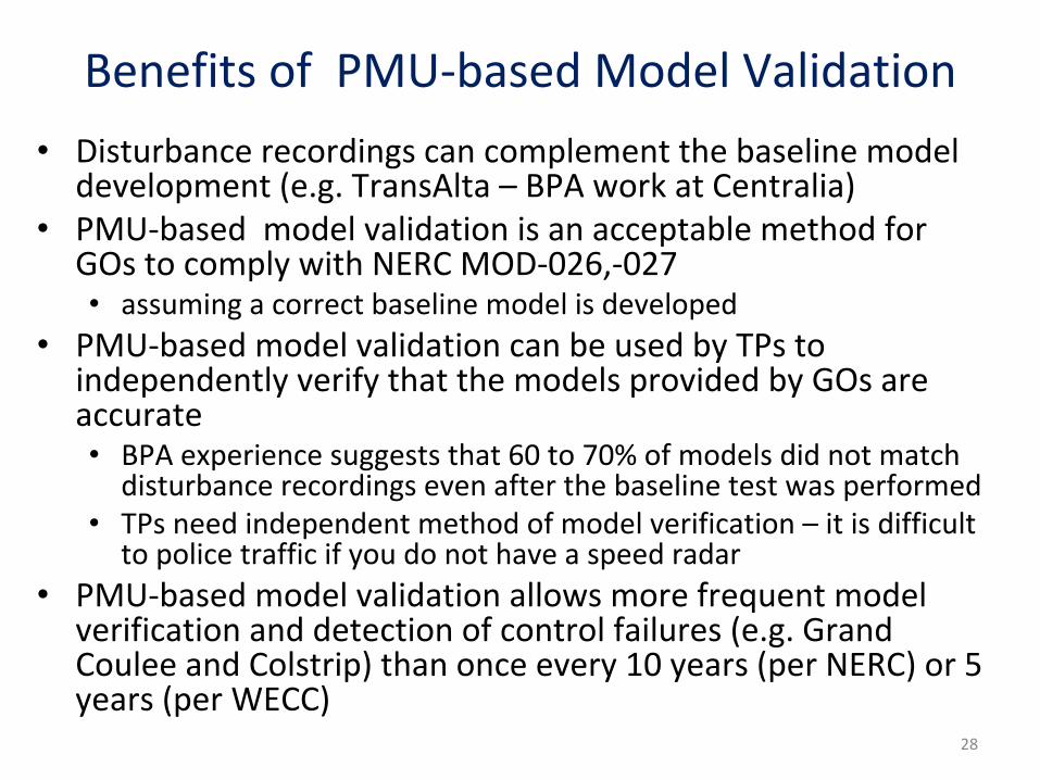
Benefits of PMU‐based Model Validation
•
Disturbance recordings can complement the baseline model
development (e.g. TransAlta – BPA work at Centralia)•
PMU‐based model validation is an acceptable method for
GOs to comply with NERC MOD‐026,‐027 •
assuming a correct baseline model is developed
•
PMU‐based model validation can be used by TPs to
independently verify that the models provided by GOs are
accurate •
BPA experience suggests that 60 to 70% of models did not match
disturbance recordings even after the baseline test was performed
•
TPs need independent method of model verification – it is difficult
to police traffic if you do not have a speed radar
•
PMU‐based model validation allows more frequent model
verification and detection of control failures (e.g. Grand
Coulee and Colstrip) than once every 10 years (per NERC) or 5
years (per WECC)28

Wind Power Plants
Wind Power Plant Model Validation
•
BPA, Idaho Power installed several PMUs at wind power plants
•
BPA is collaborating with EPRI, NREL, Enernex, UVIG, Sandia on wind power plant model validation
•
Initial results suggest more model development work is needed before models can be used in
dynamic simulations
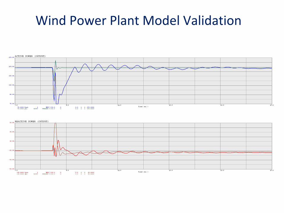
Wind Power Plant Model Validation

DemonstrationDemonstration
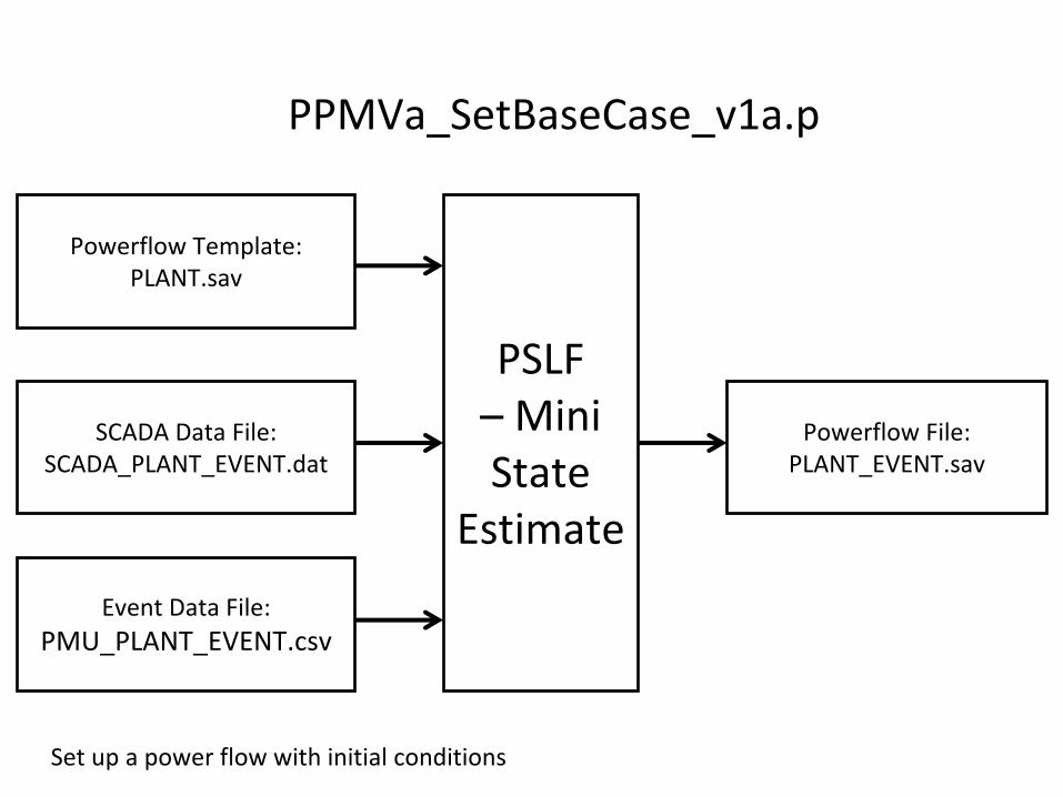
PSLF– Mini
State Estimate
Powerflow File:PLANT_EVENT.sav
Event Data File:PMU_PLANT_EVENT.csv
SCADA Data File:SCADA_PLANT_EVENT.dat
PPMVa_SetBaseCase_v1a.p
Powerflow Template:PLANT.sav
Set up a power flow with initial conditions
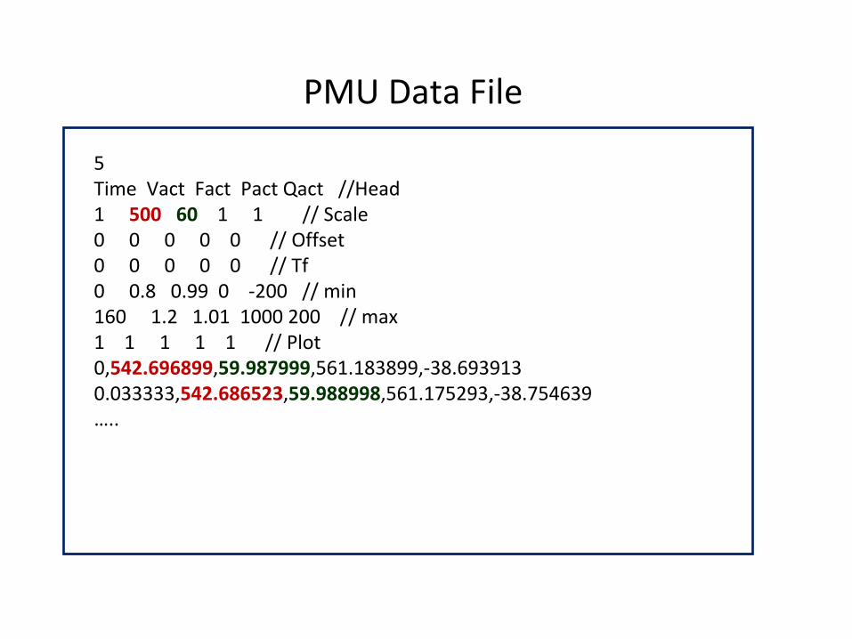
PMU Data File
5Time Vact Fact Pact Qact //Head1 500
60
1 1 // Scale0 0 0 0 0 // Offset0 0 0 0 0 // Tf0 0.8 0.99 0 ‐200 // min160 1.2 1.01 1000 200 // max1 1 1 1 1 // Plot0,542.696899,59.987999,561.183899,‐38.6939130.033333,542.686523,59.988998,561.175293,‐38.754639…..
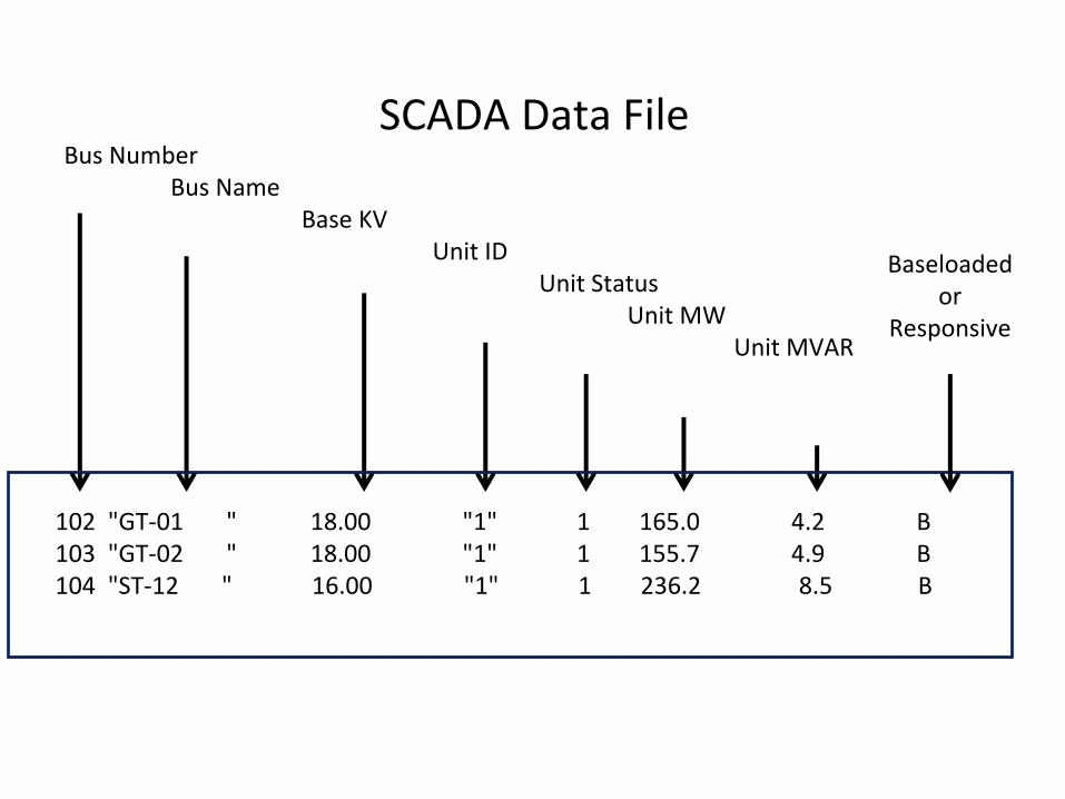
SCADA Data File
102 "GT‐01 " 18.00 "1" 1
165.0 4.2 B103 "GT‐02 " 18.00 "1" 1
155.7 4.9 B104 "ST‐12 " 16.00 "1" 1
236.2 8.5 B
Bus NumberBus Name
Base KVUnit ID
Unit StatusUnit MW
Unit MVAR
Baseloadedor
Responsive
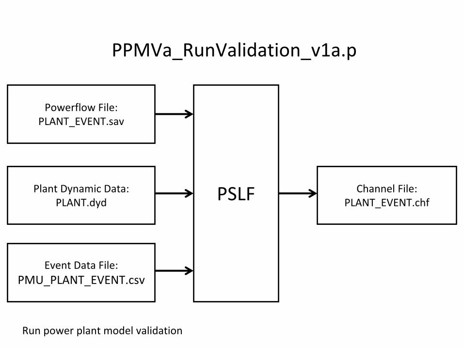
PSLF
Powerflow File:PLANT_EVENT.sav
Event Data File:PMU_PLANT_EVENT.csv
Plant Dynamic Data:PLANT.dyd
Channel File:PLANT_EVENT.chf
PPMVa_RunValidation_v1a.p
Run power plant model validation

Model Calibration
Model Calibration
•
Initially, BPA use of the PMU data has been limited to validating dynamic models of power plants:
–
used for pass / fail checking
–
no model adjustments are made should the model be
wrong
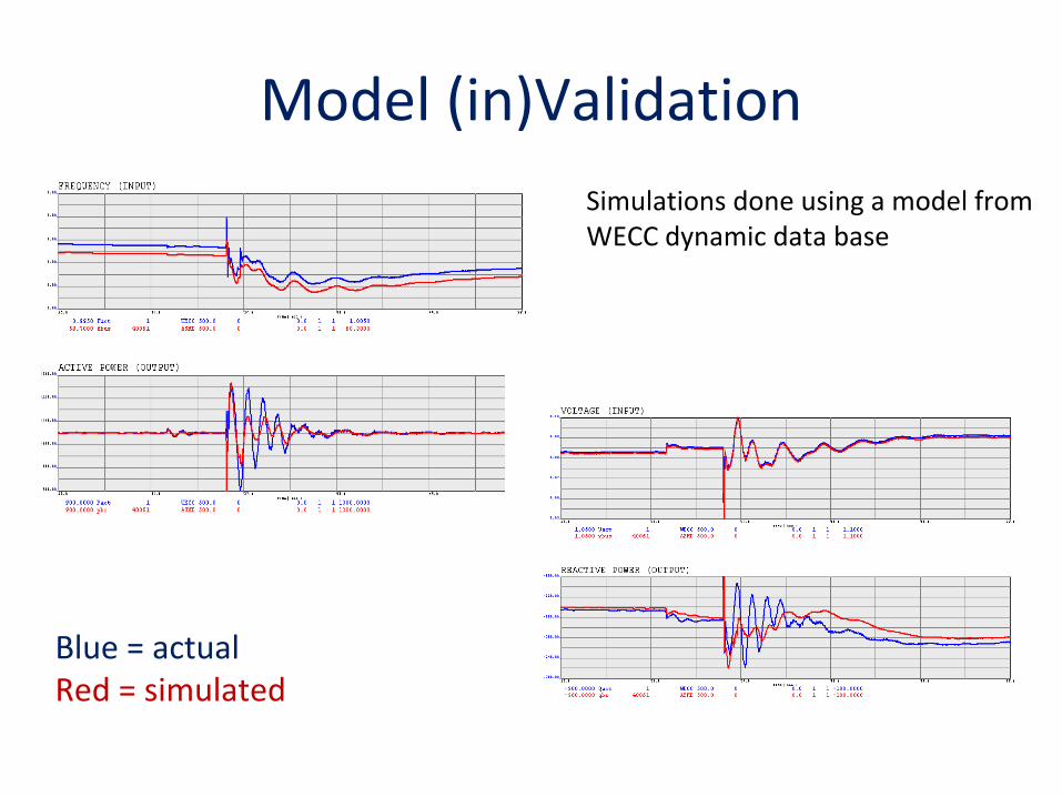
Model (in)Validation
Blue = actualRed = simulated
Simulations done using a model from
WECC dynamic data base
Model Calibration•
DOE is funding several researchers to do work on
power plant model calibration using PMU data–
PNNL (Kalman filter)
–
Sakis Meliopolis, Georgia Tech (super‐calibrator)
–
Bernard Lesieutre, University of Wisconsin (pattern
matching)
–
Wei‐Jen Lee, University of Texas (particle swarm
optimization and non‐linear optimization)
•
EPRI is also working on PMU‐based model calibration
•
BPA has worked with Bernie Lesieutre to perform model calibration for CGS and Colstrip
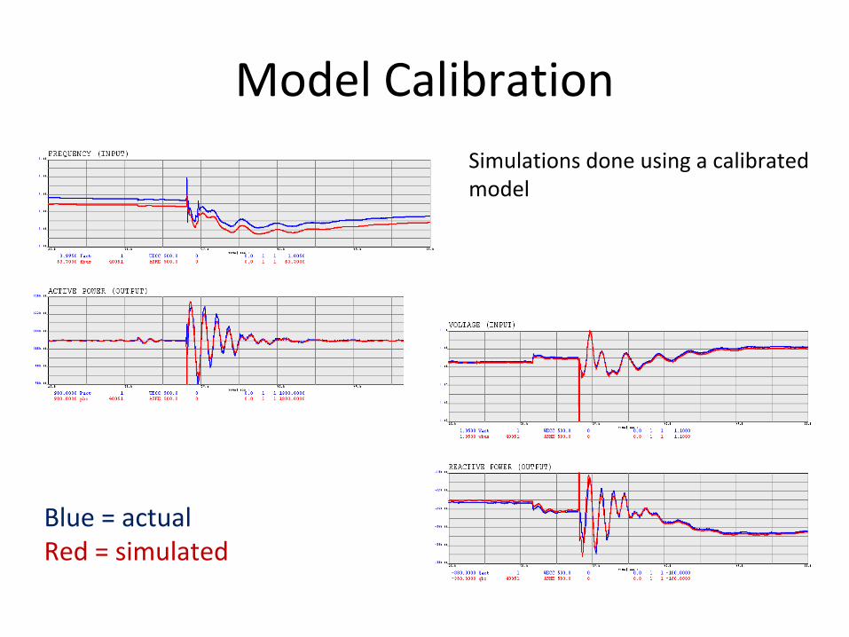
Model Calibration
Blue = actualRed = simulated
Simulations done using a calibrated
model
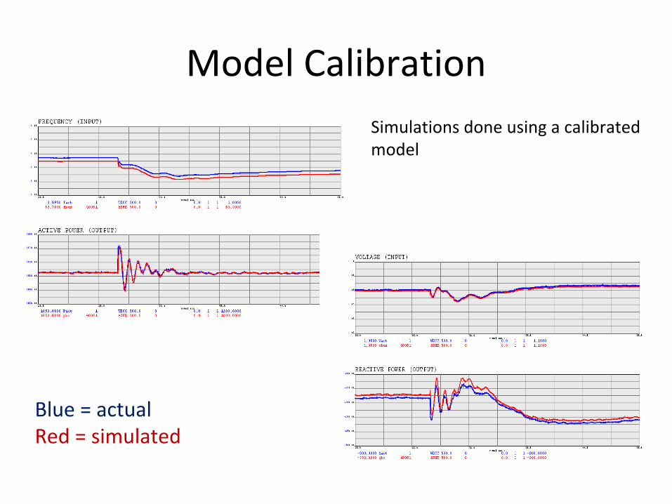
Model Calibration
Blue = actualRed = simulated
Simulations done using a calibrated
model
Contact Information
•
Dmitry Kosterev, BPA, [email protected]
•
Steve Yang, BPA, [email protected]
•
Pavel
Etingov, PNNL, [email protected]
•
Bernie Lesieutre, University of Wisonsin
•
Shawn Patterson, USBR