Embed Size (px)
Citation preview
International Journal of Advances in Engineering & Technology, Sept. 2013.
©IJAET ISSN: 22311963
1855 Vol. 6, Issue 4, pp. 1855-1868
POWER QUALITY COMPENSATION USING SMES
COIL WITH FLC
M. Manikandan1, A. Mahabub Basha2 1Department of Electrical and Electronics Engineering,
Erode Sengunthar Engineering College, Thudupathi, Erode, T.N., India 2Department of Electronics and Communication Engineering,
K. S. R. College of Engineering, Thiruchengode, T.N., India
ABSTRACT This paper presents a Power quality compensation using SMES (Superconducting Magnetic Energy Storage)
Coil with FLC (Fuzzy Logic Control) to protect consumers from the voltage Sag. Using the proposed control
strategy, the voltage of the inverter capacitors in SMES can be independently controlled; also, the minimum
power and switching losses as well as the proper convection can be achieved using this same strategy. The
distribution network, sensitive industrial loads and critical commercial operations suffer from outages and
service interruptions which can cost financial losses to both utility and consumers.To investigate the
effectiveness and reliability of the proposed approach in stabilizing capacitor voltage, SMES performance using
the presented approach is compared with that of SMES when the capacitors of the three-level inverter are
replaced with equal and ideal voltage sources. Due to the characteristic of high energy density and quick
response, a superconducting magnet is selected as the energy storage unit to improve the compensation
capability in Power system. The compensation capability of a SMES Coil depends primarily on the maximum
voltage injection ability and the amount of stored energy available within the Coil. SMES Coil can provide the
most commercial solution to mitigation voltage sag by injecting voltage as well as power into the system. By
using the Fuzzy Logic controller the number of membership function can be minimized and the time response of
controller become faster.This comparison is carried out from the power-quality point of view and it is shown
that the proposed switching strategy with a Fuzzy Logic Controller is highly reliable. Using MATLAB Simulink,
the models of the SMES with FLC is established, and the simulation tests are performed to evaluate the system
performance.
INDEX TERM - Power quality, DVR, SMES, Fuzzy Logic controller, Voltage Sag.
I. INTRODUCTION
Power quality is one of the most important topic that electrical engineering have been noticed in
recent years. Voltage sag is one of the problems related to power quality. This phenomenon happen
continuously in transmission and distribution systems. Power quality problems, such as voltage sag
which arise due to a fault or a pulsed load, can cause interruption on critical load. Even relay and
conductors in motor starters can be sensitive to voltage sag resulting in shutdown of a process.
Improper operation of the equipment has cased reduction in the business revenue and also losses to
the environment. Voltage sag are very hazardous during the control of equipment in the process
industry. Any failure of control result in the breakdown of process and, therefore, loss of raw
materials and production time and event risk to human life.
DVR installed on a sensitive load, restores the line voltage to its nominal value within the response
time of a few milliseconds thus avoiding any power disruption to the load. Modem Pulse-Width
Modulated (PWM) inverters capable of generating accurate high quality voltage waveforms form the
power electronic heart of the new Custom Power devices. Because the performance of the overall
International Journal of Advances in Engineering & Technology, Sept. 2013.
©IJAET ISSN: 22311963
1856 Vol. 6, Issue 4, pp. 1855-1868
control system largely depends on the quality of the applied control strategy, a high performance -
controller with fast transient response and good steady state characteristics is required [1].
The DVR supplies the active power with help of SMES and required reactive power is generated
internally without any means SMES storage. DVR can compensate voltage at both transmission and
distribution sides. Usually a DVR is installed on a critical load feeder. During the normal operating
condition (without sag condition) DVR operates in a low loss standby mode [3]. During this condition
the DVR is said to be in steady state. When a disturbance occurs (abnormal condition) and supply
voltage deviates from nominal value, DVR supplies voltage for compensation of sag and is said to be
in transient state. The DVR is connected in series between the load and the supply voltage [3].
Fuzzy polar first introduced by Takashi Hiyama in 1991. Fuzzy Polar is a decision that the optimal
method of mapping the signal in polar areas. These parameters are controlled by Fuzzy Polar on polar
fields.. Each position in the polar areas represents major control signals required. The main principle
of the fuzzy polar shift which determines the magnitude of the input signal to be controlled to the
equilibrium conditions (desired conditions). Signal to be controlled is represented in two polar
parameters of magnitude and angle. In the basic application, the function of the fuzzy polar controller
is used to replace the function of the PI (Hiyama et. Al., 1993). Control signal given by the fuzzy
polar to be robust so that the input signal provides a more optimal results. [7]
DVRs in general on the three wire method using blocking transformer with the assumption that the
fault is a three phase ground fault. When an interruption occurs, the components of one phase ground
zero with a role big enough so that the resulting lack of a good recovery (Chung et. Al., 2001) using
four-wire, zero sequence is controlled zero so that the resulting good restore voltage.
Recently new FL methods have been applied to Custom Power Devices, especially for active power
filters .The operation of DVR is similar to that of active power filters in that both compensators must
respond very fast on the request from abruptly changing reference signals. FL control of DVR in the
literature is reported only in [8]. Three-phase supply voltages are transformed into d and q
coordinates. The reference values for Vd and V are compared with these transformed values and then
voltage errors are obtained. Two qFL controllers evaluating 81 linguistic rules process these errors.
Resulting outputs are re-transformed into three-phase domain and compared with a carrier signal to
generate PWM inverter signals. The DVR in [1] has no sag detection function, which means that the
device is always in operation and generates compensating voltage also for small voltage drops within
10% that causes high losses. In Ref. [1], the results only for balanced sags are presented.
This paper presents a dynamic voltage restorer (DVR) using SMES coil capable of handling deep sags
including outage on a low voltage distribution system using Fuzzy Logic controller. This paper aims
to create a DVR-based fuzzy logic controller for improving voltage sag in power system. So we get
better results and recovery voltage during voltage sags can be achieved without the shift in nominal
voltage phase angle and harmonics can be well damped. The results of this simulation show that DVR
based fuzzy logic controller can compensate balanced voltage sag better than PI controller.The
proposed DVR has the capability of both balanced and unbalanced voltage sag/swell compensation
and can track changes in supply phase. It can easily be implemented in real time application.
Section II explains the PQ SMES Coil based DVR with FLC Model, section III describes the
Dynamic Voltage Restorer (DVR), section IV explains the Superconducting Magnetic Energy Storage
(SMES) in DVR, section V explains the Inverter Control Strategies of DVR, section VI presents the
simulation results and discussions and section VII gives the conclusion
International Journal of Advances in Engineering & Technology, Sept. 2013.
©IJAET ISSN: 22311963
1857 Vol. 6, Issue 4, pp. 1855-1868
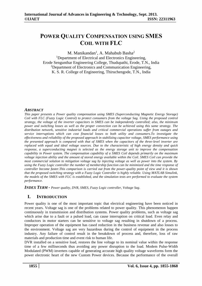
Figure 1.1. SMES Based DVR with FLC
II. PQ SMES COIL BASED DVR WITH FLC MODEL
Typically basic configuration DVR consists of Booster Transformer, Voltage Source Inverter, System
Control, Energy Storage which consists of the source DC and Blocking Transformer. When an
interruption occurs, the voltage at the sensitive load bus has decreased. Booster transformer inject
voltage transformer will provide in accordance with the decrease in voltage at load bus voltage at load
bus so sensitive to be constant. Booster Transformer get the injection voltage source from the Voltage
Source Inverter (VSI) which is controlled by the Voltage Regulator. The amount of voltage injection
given by Voltage Source Inverter (VSI) was formulated as follows:
Ul= Us+ U inj (1)
where,
Ul = voltage sensitive load
Us = voltage sags
U inj = voltage injection
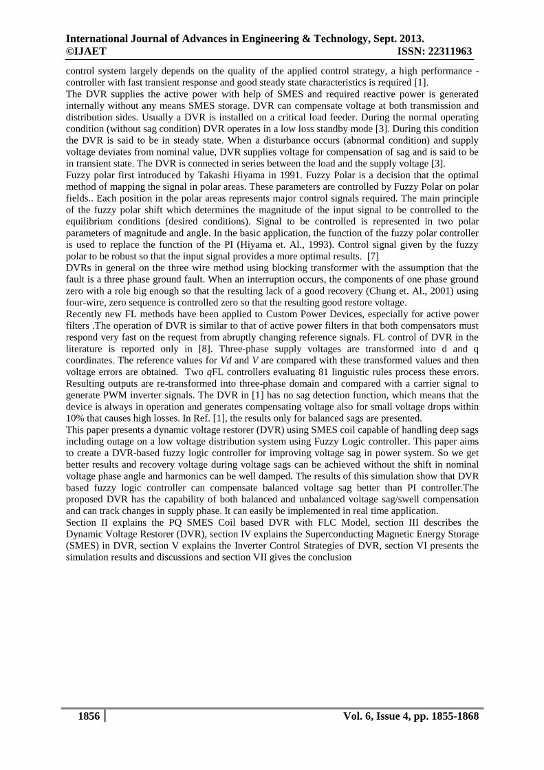
Installation DVR on a simple distribution system model shown in Figure 2.1
Figure 2.1 Distribution system model with the installation of a typically DVR.
When the voltage sags into a voltage asymmetry is restored to normal voltage symmetry. At normal
voltage conditions, the power load on each phase can be written as follows.
(2)
where,
I l = load current
Pl= active power
Ql= reactive power
To obtain the recovery voltage is required injection power from the DVR so that the power flow of
each phase is shown in equation (2.3).

International Journal of Advances in Engineering & Technology, Sept. 2013.
©IJAET ISSN: 22311963
1858 Vol. 6, Issue 4, pp. 1855-1868
(3)
where,
(P+ jQ )s represents sags quantity
(P+ jQ) inj represents DVR injection quantity
Blocking Transformer on conventional DVR is used to prevent voltage / zero sequence currents that
occurred at the time of disturbance on the bus or other feeder that led to sensitive load. Blocking
Transformer which installed on system with winding configuration Y-∆ caused zero sequence
impedance infinite. However Blocking Transformer can’t operate on 3 phase 4 wire system. So we
need a controller that can control the zero sequence components when single phase to ground fault
occurs.
In the distribution system with neutral point grounding, most faults are single phase to ground
disturbance. Single phase to ground fault on the normal load feeder will result in voltage sags on the
feeder sensitive load. Phasor diagram when there is a single phase to ground disturbance is shown in
Figure 2.2. Condition of voltage at the sensitive load prior to fault can be described in equation (4, 5,
6).
(4)
(5)
(6)
Figure 2.2. Phasor voltage of three phases during a phase to fault ground
During the disturbances, the voltage equation can be written into,
(7)
where,
V = magnitude sags voltage
ð= phase angle jump
Zero sequence components during fault can be explained in the following:
International Journal of Advances in Engineering & Technology, Sept. 2013.
©IJAET ISSN: 22311963
1859 Vol. 6, Issue 4, pp. 1855-1868
(8)
From equation (8) shows that zero sequence components was not equal to 0. This shows that the zero
sequence components must be compensation. Compensation method d, q and 0 for voltage regulator
control DVR using Fuzzy logic controller, modeled in Figure 2.2.
III. DYNAMIC VOLTAGE RESTORER (DVR)
The conventional circuit configuration of the DVR is shown in Figure 3.1 Dynamic voltage restorer is
a series connected device is used for mitigating voltage disturbances in the distribution system (Lee,
et al., 2004). The DVRs can be used and are already in operation (W.E. Brumsickle, et al., 2001).
DVR maintains the load voltage at a nominal magnitude and phase by compensating the voltage
sag/swell, voltage unbalance and voltage harmonics presented at the point of common coupling
(Mahesh, et al., 2008; Jowder, et al., 2009; Ramachandaramurthy, et al., 2004). These systems are
able to compensate voltage sags by increasing the appropriate voltages in series with the supply
voltage, and therefore avoid a loss of power. In 1994, L.Gyugyi (Patent No. 5329222) proposed an
apparatus and a method for dynamic voltage restoration of utility distribution network. This method
uses real power in order to inject the faulted supply voltages and is commonly known as the Dynamic
Voltage Restorer (Gyugyi, et al., 1994). The DVR should capable to react as fast as possible to inject
the missing voltage to the system due to sensitive loads are very sensitive to voltage variations (Chan,
et al., 2006). The DVR is a series conditioner based on a pulse width modulated voltage source
inverter, which is generating or absorbing real or reactive power independently. Voltage sags caused
by unsymmetrical line-to line, line to ground, double-line-to-ground and symmetrical three phase
faults is affected to sensitive loads, the DVR injects the independent voltages to restore and
maintained sensitive to its nominal value. The compensation of harmonics and mitigates voltage
transients has been discussed in (Li, et al., 2001).
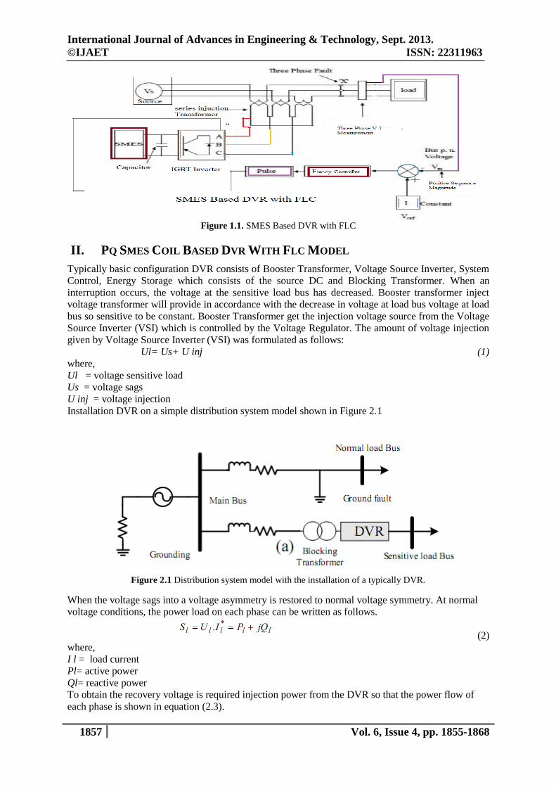
Figure 3.1. Dynamic Voltage Restorer (DVR)
The DVR device consists of five main sections; (i) Energy Storage Unit: It is responsible for energy
storage in DC form. Flywheels, lead acid batteries, Superconducting Magnetic Energy Storage
(SMES) and Super-Capacitors can be used as energy storage devices, the estimates of the typical
energy efficiency of four energy storage technologies are: batteries – 75 %, Fly wheel – 80 %,
Compressed air – 80%, SMES – 90% [5]. (ii) Inverter: It is used to convert DC power to AC power
[6]. (iii) Passive Filters: It is clear that higher order harmonic components distort the compensated
output voltage. Filter is used to convert the PWM inverted pulse waveform into a sinusoidal
International Journal of Advances in Engineering & Technology, Sept. 2013.
©IJAET ISSN: 22311963
1860 Vol. 6, Issue 4, pp. 1855-1868
waveform. This is achieved by removing the unnecessary higher order harmonic components
generated from the DC to AC conversion in the VSI. (iv) By-Pass Switch: This switch is used to
protect the inverter from high currents. In case of a fault or a short circuit on downstream, the DVR
changes into the bypass condition where the VSI inverter is protected against over current flowing
through the power semiconductor switches [3]. (v) Voltage Injection Transformers: In a three-phase
system, three Single-phase transformer units or one three phase transformer unit can be used for
voltage injection purpose [3].
IV. SUPERCONDUCTING MAGNETIC ENERGY STORAGE (SMES) IN DVR
SMES is stores energy in the magnetic field developed due to the flow of direct current in a coil of
superconducting material cooled below its critical temperature. Stored energy can be released by
discharging the coil whenever required. To maintain the coil in its superconducting state, it is
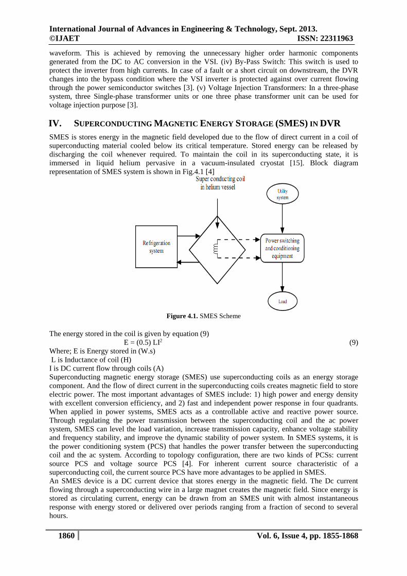
immersed in liquid helium pervasive in a vacuum-insulated cryostat [15]. Block diagram
representation of SMES system is shown in Fig.4.1 [4]
Figure 4.1. SMES Scheme
The energy stored in the coil is given by equation (9)
E = (0.5) LI2 (9)
Where; E is Energy stored in (W.s)
L is Inductance of coil (H)
I is DC current flow through coils (A)
Superconducting magnetic energy storage (SMES) use superconducting coils as an energy storage
component. And the flow of direct current in the superconducting coils creates magnetic field to store
electric power. The most important advantages of SMES include: 1) high power and energy density
with excellent conversion efficiency, and 2) fast and independent power response in four quadrants.
When applied in power systems, SMES acts as a controllable active and reactive power source.
Through regulating the power transmission between the superconducting coil and the ac power
system, SMES can level the load variation, increase transmission capacity, enhance voltage stability
and frequency stability, and improve the dynamic stability of power system. In SMES systems, it is
the power conditioning system (PCS) that handles the power transfer between the superconducting
coil and the ac system. According to topology configuration, there are two kinds of PCSs: current
source PCS and voltage source PCS [4]. For inherent current source characteristic of a
superconducting coil, the current source PCS have more advantages to be applied in SMES.
An SMES device is a DC current device that stores energy in the magnetic field. The Dc current
flowing through a superconducting wire in a large magnet creates the magnetic field. Since energy is
stored as circulating current, energy can be drawn from an SMES unit with almost instantaneous
response with energy stored or delivered over periods ranging from a fraction of second to several
hours.
International Journal of Advances in Engineering & Technology, Sept. 2013.
©IJAET ISSN: 22311963
1861 Vol. 6, Issue 4, pp. 1855-1868
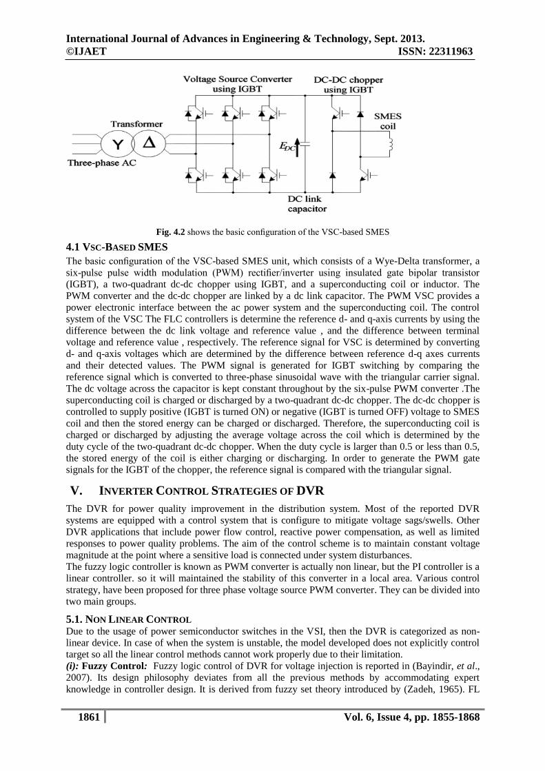
Fig. 4.2 shows the basic configuration of the VSC-based SMES
4.1 VSC-BASED SMES
The basic configuration of the VSC-based SMES unit, which consists of a Wye-Delta transformer, a
six-pulse pulse width modulation (PWM) rectifier/inverter using insulated gate bipolar transistor
(IGBT), a two-quadrant dc-dc chopper using IGBT, and a superconducting coil or inductor. The
PWM converter and the dc-dc chopper are linked by a dc link capacitor. The PWM VSC provides a
power electronic interface between the ac power system and the superconducting coil. The control
system of the VSC The FLC controllers is determine the reference d- and q-axis currents by using the
difference between the dc link voltage and reference value , and the difference between terminal
voltage and reference value , respectively. The reference signal for VSC is determined by converting
d- and q-axis voltages which are determined by the difference between reference d-q axes currents
and their detected values. The PWM signal is generated for IGBT switching by comparing the
reference signal which is converted to three-phase sinusoidal wave with the triangular carrier signal.
The dc voltage across the capacitor is kept constant throughout by the six-pulse PWM converter .The
superconducting coil is charged or discharged by a two-quadrant dc-dc chopper. The dc-dc chopper is
controlled to supply positive (IGBT is turned ON) or negative (IGBT is turned OFF) voltage to SMES
coil and then the stored energy can be charged or discharged. Therefore, the superconducting coil is
charged or discharged by adjusting the average voltage across the coil which is determined by the
duty cycle of the two-quadrant dc-dc chopper. When the duty cycle is larger than 0.5 or less than 0.5,
the stored energy of the coil is either charging or discharging. In order to generate the PWM gate
signals for the IGBT of the chopper, the reference signal is compared with the triangular signal.
V. INVERTER CONTROL STRATEGIES OF DVR
The DVR for power quality improvement in the distribution system. Most of the reported DVR
systems are equipped with a control system that is configure to mitigate voltage sags/swells. Other
DVR applications that include power flow control, reactive power compensation, as well as limited
responses to power quality problems. The aim of the control scheme is to maintain constant voltage
magnitude at the point where a sensitive load is connected under system disturbances.
The fuzzy logic controller is known as PWM converter is actually non linear, but the PI controller is a
linear controller. so it will maintained the stability of this converter in a local area. Various control
strategy, have been proposed for three phase voltage source PWM converter. They can be divided into
two main groups.
5.1. NON LINEAR CONTROL Due to the usage of power semiconductor switches in the VSI, then the DVR is categorized as non-
linear device. In case of when the system is unstable, the model developed does not explicitly control
target so all the linear control methods cannot work properly due to their limitation.
(i): Fuzzy Control: Fuzzy logic control of DVR for voltage injection is reported in (Bayindir, et al.,
2007). Its design philosophy deviates from all the previous methods by accommodating expert
knowledge in controller design. It is derived from fuzzy set theory introduced by (Zadeh, 1965). FL
International Journal of Advances in Engineering & Technology, Sept. 2013.
©IJAET ISSN: 22311963
1862 Vol. 6, Issue 4, pp. 1855-1868
controllers are an attractive choice when precise mathematical formulations are not possible. In
(Jurado, et al., 2004) discussed about the implementation of FL in DVR. The advantages of this
controller is capability to reduced the error and transient overshoot of PWM.
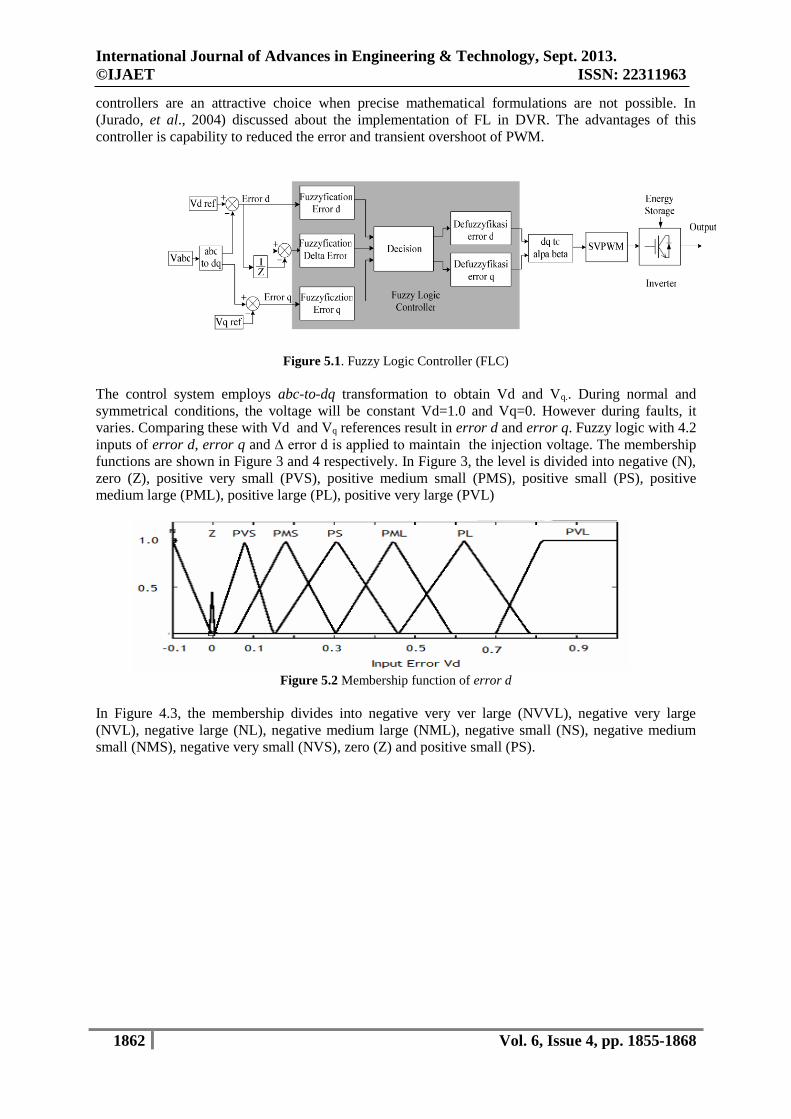
Figure 5.1. Fuzzy Logic Controller (FLC)
The control system employs abc-to-dq transformation to obtain Vd and Vq.. During normal and
symmetrical conditions, the voltage will be constant Vd=1.0 and Vq=0. However during faults, it
varies. Comparing these with Vd and Vq references result in error d and error q. Fuzzy logic with 4.2
inputs of error d, error q and ∆ error d is applied to maintain the injection voltage. The membership
functions are shown in Figure 3 and 4 respectively. In Figure 3, the level is divided into negative (N),
zero (Z), positive very small (PVS), positive medium small (PMS), positive small (PS), positive
medium large (PML), positive large (PL), positive very large (PVL)
Figure 5.2 Membership function of error d
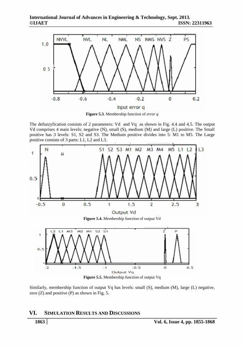
In Figure 4.3, the membership divides into negative very ver large (NVVL), negative very large
(NVL), negative large (NL), negative medium large (NML), negative small (NS), negative medium
small (NMS), negative very small (NVS), zero (Z) and positive small (PS).
International Journal of Advances in Engineering & Technology, Sept. 2013.
©IJAET ISSN: 22311963
1863 Vol. 6, Issue 4, pp. 1855-1868
Figure 5.3. Membership function of error q
The defuzzyfication consists of 2 parameters: Vd and Vq as shown in Fig. 4.4 and 4.5. The output
Vd comprises 4 main levels: negative (N), small (S), medium (M) and large (L) positive. The Small
positive has 3 levels: S1, S2 and S3. The Medium positive divides into 5: M1 to M5. The Large
positive consists of 3 parts: L1, L2 and L3.
Figure 5.4. Membership function of output Vd
Figure 5.5. Membership function of output Vq
Similarly, membership function of output Vq has levels: small (S), medium (M), large (L) negative,
zero (Z) and positive (P) as shown in Fig. 5.
VI. SIMULATION RESULTS AND DISCUSSIONS
International Journal of Advances in Engineering & Technology, Sept. 2013.
©IJAET ISSN: 22311963
1864 Vol. 6, Issue 4, pp. 1855-1868
A detailed simulation of the SMES Coil based DVR with FLC (Fuzzy Logic Controller) system was
performing using MATLAB/SIMULINK program in order to verify the operation. The parameter of
the system are as follows (Table- 6.1)
Table -6.1 System Parameters S.No Item Parameters
1 Supply Voltage 380V,50Hz
2 Serious Transformer turns ratio 1:2
3 DC link voltage 400V
4 Filter inductance 6mH
5 Filter Capacitance 4 micro F.
6 Load resistance 200 ohm
7 Load inductance 2.5H
8 Converter rating power 8KvA
9 Switching frequency of converter 5kHz
10 SC rating Energy storage 12.5KJ
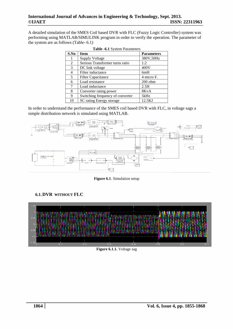
In order to understand the performance of the SMES coil based DVR with FLC, in voltage sags a
simple distribution network is simulated using MATLAB.
Figure 6.1. Simulation setup
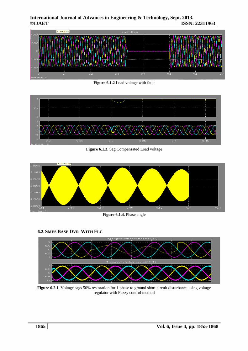
6.1. DVR WITHOUT FLC
Figure 6.1.1. Voltage sag
International Journal of Advances in Engineering & Technology, Sept. 2013.
©IJAET ISSN: 22311963
1865 Vol. 6, Issue 4, pp. 1855-1868
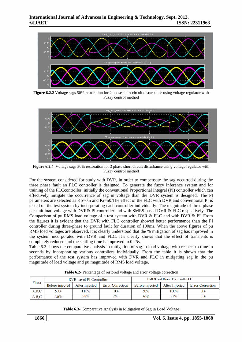
Figure 6.1.2 Load voltage with fault
Figure 6.1.3. Sag Compensated Load voltage
Figure 6.1.4. Phase angle
6.2. SMES BASE DVR WITH FLC
Figure 6.2.1. Voltage sags 50% restoration for 1 phase to ground short circuit disturbance using voltage
regulator with Fuzzy control method
International Journal of Advances in Engineering & Technology, Sept. 2013.
©IJAET ISSN: 22311963
1866 Vol. 6, Issue 4, pp. 1855-1868
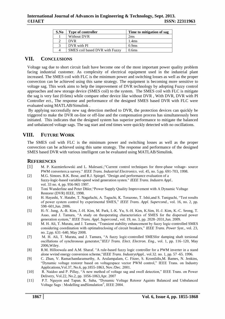
Figure 6.2.2 Voltage sags 50% restoration for 2 phase short circuit disturbance using voltage regulator with
Fuzzy control method
Figure 6.2.4. Voltage sags 50% restoration for 3 phase short circuit disturbance using voltage regulator with
Fuzzy control method
For the system considered for study with DVR, in order to compensate the sag occurred during the
three phase fault an FLC controller is designed. To generate the fuzzy inference system and for
training of the FLCcontroller, initially the conventional Proportional Integral (PI) controller which can
effectively mitigate the occurrence of sag in voltage than the DVR system is designed. The PI
parameters are selected as Kp=0.5 and Ki=50.The effect of the FLC with DVR and conventional PI is
tested on the test system by incorporating each controller individually. The magnitude of three-phase
per unit load voltage with DVR& PI controller and with SMES based DVR & FLC respectively. The
Comparison of pu RMS load voltage of a test system with DVR & FLC and with DVR & PI. From
the figures it is evident that the DVR with FLC controller showed better performance than the PI
controller during three-phase to ground fault for duration of 100ms. When the above figures of pu
RMS load voltages are observed, it is clearly understood that the % mitigation of sag has improved in
the system incorporated with DVR and FLC. It’s clearly shows that the effect of transients is
completely reduced and the settling time is improved to 0.25s.
Table.6.2 shows the comparative analysis in mitigation of sag in load voltage with respect to time in
seconds by incorporating various controllers individually. From the table it is shown that the
performance of the test system has improved with DVR and FLC in mitigating sag in the pu
magnitude of load voltage and pu magnitude of RMS load voltage.
Table 6.2- Percentage of restored voltage and error voltage correction
Table 6.3- Comparative Analysis in Mitigation of Sag in Load Voltage
International Journal of Advances in Engineering & Technology, Sept. 2013.
©IJAET ISSN: 22311963
1867 Vol. 6, Issue 4, pp. 1855-1868
S.No Type of controller Time to mitigation of sag
1 Without DVR 2ms
2 DVR 1.4ms
3 DVR with PI 0.9ms
4 SMES coil based DVR with Fuzzy 0.6ms
VII. CONCLUSIONS
Voltage sag due to short circuit fault have become one of the most important power quality problem
facing industrial customer. As complexity of electrical equipment used in the industrial plant
increased. The SMES coil with FLC is the minimum power and switching losses as well as the proper
convection can be achieved using this same strategy. The equipment is becoming more sensitive to
voltage sag. This work aims to help the improvement of DVR technology by adopting Fuzzy control
approaches and new storage device (SMES coil) to the system. The SMES coil with FLC is mitigate
the sag is very fast (0.6ms) while compare other device like without DVR , With DVR, DVR with PI
Controller ect., The response and performance of the designed SMES based DVR with FLC were
evaluated using MATLAB/Simulink .
By applying successfully new sag detection method to DVR, the protection devices can quickly be
triggered to make the DVR on-line or off-line and the compensation process has simultaneously been
initiated. This indicates that the designed system has superior performance to mitigate the balanced
and unbalanced voltage sags. The sag start and end times were quickly detected with no oscillations.
VIII. FUTURE WORK
The SMES coil with FLC is the minimum power and switching losses as well as the proper
convection can be achieved using this same strategy. The response and performance of the designed
SMES based DVR with various intelligent can be evaluated using MATLAB/Simulink.
REFERENCES [1] M. P. Kazmierkowski and L. Malesani.;"Current control techniques for three-phase voltage- source
PWM converters:a survey." IEEE Trans. Industrial Electronics. vol. 45, no. 5.pp. 691-703, 1998.
[2] M.G. Simoes. B.K. Bose, and R.J. Spiegel. "Design and performance evaluation of a
fuzzy-logic-based variable-speed wind generation systen." IEEE Trans. Industrn Appl..
vol. 33 no. 4, pp. 956-965 1997.
[3] Toni Wunderline and Peter Dhler,“Power Supply Quality Improvement with A Dynamic Voltage
Restorer (DVR) IEEE, 1998.
[4] H. Hayashi, Y. Hatabe, T. Nagafuchi, A. Taguchi, K. Terazono, T. Ishii,and S. Taniguchi, “Test results
of power system control by experimental SMES,” IEEE Trans. Appl. Supercond., vol. 16, no. 2, pp.
598–601,Jun. 2006.
[5] H.-Y. Jung, A.-R. Kim, J.-H. Kim, M. Park, I.-K. Yu, S.-H. Kim, K.Sim, H.-J. Kim, K.-C. Seong, T.
Asao, and J. Tamura, “A study on theoperating characteristics of SMES for the dispersed power
generation system,” IEEE Trans. Appl. Supercond., vol. 19, no. 3, pp. 2028–2031,Jun. 2009.
[6] M. H. Ali, T. Murata, and J. Tamura, “Transient stability enhancement by fuzzy logic-controlled SMES
considering coordination with optimalreclosing of circuit breakers,” IEEE Trans. Power Syst., vol. 23,
no. 2,pp. 631–640, May 2008.
[7] M. H. Ali, T. Murata, and J. Tamura, “A fuzzy logic-controlled SMESfor damping shaft torsional
oscillations of synchronous generator,”IEEJ Trans. Elect. Electron. Eng., vol. 1, pp. 116–120, May
2006,Wiley.
[8] R.M. Hilloowala and A.M. Sharaf. "A rule-based fuzzy logic controller for a PWM inverter in a stand
alone wvind energy conversion scheme,"IEEE Trans. IndustrytAppl.. vol.32. no. 1, pp. 57 -65. 1996.
[9] C. Zhan, V. Ramachandaramurthy, A. Arulampalam, C. Fitzer, S. Kromlidis,M. Bames, N. Jenkins,
“Dynamic voltage restorer based on voltagespace vector PWM control,” IEEE Trans. on Industry
Applications,Vol.37, No.6, pp.1855-1863, Nov./Dec. 2001.
[10] R. Naidoo and P. Pillay, “A new method of voltage sag and swell detection,” IEEE Trans. on Power
Delivery, Vol.22, No.2, pp. 1056-1063,Apr. 2007
[11] P.T. Nguyen and Tapan. K. Saha, “Dynamic Voltage Retorer Againts Balanced and Unbalanced
Voltage Sags : Modelling andSimulation”, IEEE 2004.
International Journal of Advances in Engineering & Technology, Sept. 2013.
©IJAET ISSN: 22311963
1868 Vol. 6, Issue 4, pp. 1855-1868
[12] Pujiantara, M., Mauridhi Hery P, Mochamad Ashari, Zaenal PA, T Hiyama, “Dynamic Voltage
Restorer Based on Fuzzy Polar asVoltage Sag Restorer and Voltage Distortion Compensator”, ICA
conference, Bandung, 2009.
[13] Nielsen, J. G., Newman, M., Nielsen, H., and Bllabjerg, F.:‘Control and Testing of a Dynamic Voltage
Restorer (DVR) at Medium Voltage Level’, IEEE Transactions on Power Electronics, 2004, 19, (3),
pp.806-813
[14] C. Zhang,PWMConverter and Its Control. Beijing, China: Mechanic Industry, 2003, p.62.
[15] ”Detailed Modeling of Superconducting Magnetic Energy Storage (SMES) System” IEEE Task
ForceFACTS andCustom-Power Controllers, T&D Com “
[16] Voltage sag mitigation in offshore oil rig power system using smes based DVR Di Wu, C. S. Chang
Department of Electrical and Computer Engineering, National University of Singapore, 4, Engineering
Drive 3, Singapore 117576
[17] K. Shikimachi, H. Moriguchi, and N. Hirano et al., “Development of MVA class HTS SMES system
for bridging instantaneous voltage dips,” IEEE Trans. Applied Superconductivity, vol. 15, no. 2,
pp.1931–1934, 2005.
[18] JoãoM.Pina, J. M. Ceballos and A. Álvarez, Member, IEEE “A Fast Algorithm for Initial Design of
HTS Coils for SMES Applications” IEEE Trans. Applied Superconductivity, vol. 23,No.3, June 2013.
[19] Seung-Tak Kim, Byung-Kwan Kang and Sun-Ho Bae Member, IEEE “Application of SMES and Grid
Code Compliance to Wind/Photovoltaic Generation System” IEEE Trans. Applied Superconductivity,
vol. 23, no. 3, June 2013.
[20] A. M. Shiddiq Yunus, A. Abu-Siada, and M. A. S. Masoum, Member, IEEE “Application of SMES
Unit to Improve DFIG Power Dispatch and Dynamic Performance During Intermittent Misfire and
Fire-Through Faults” IEEE Trans. Applied Superconductivity, vol. 23, no. 4, August 2013.
[21] B. Vincent, P. Tixador, T. Lecrevisse, J.-M. Rey, X. Chaud, and Y. Miyoshi “HTS Magnets:
Opportunities and Issues for SMES” ” IEEE Trans. Applied Superconductivity, vol. 23, no. 3, June
2013.
BIOGRAPHIES M. Manikandan is the research scholar in EEE Department, and Faculty in EEE
Department of Erode Sengunthar Engineering College, Tamilnadu ,India. His research
interest include the power quality compensation techniques in fuzzy logic control in power
systems.
A. Mahabub Basha is the Director in ECE Department K.S.R. College of Engineering
Tamilnadu, India His research interests include application of soft computing techniques in
power system problems.