Embed Size (px)
DESCRIPTION
switch-gear of power system
Citation preview

Topic 4
Power Switchgear
0
Switchgears
Outline
• Introduction to power switchgear
• AC power network switching duties (optional)
• Circuit breaker and fuse selection (Sect 7.5 Text)
Switchgears
1
Outline
• Introduction to power switchgear
• AC power network switching duties (optional)
• Circuit breaker and fuse selection (Sect 7.5 Text)
Switchgears
2
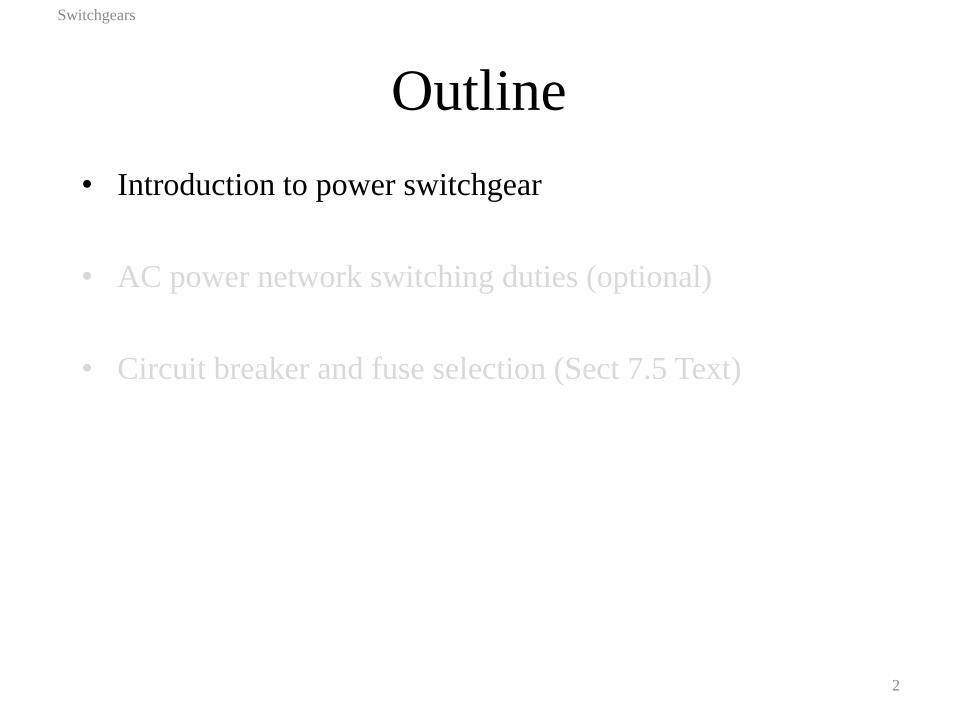
Roles of switchgear
• Load connection and disconnection
• Interrupt fault currents
• Isolate circuits
• The switching device must be able to
– Turn on or interrupt electrical currents
– Switch very low currents (no load currents) and very high currents (fault currents)
– Dissipate energy released at high rate while interrupting high currents
– Withstand transient recovery voltage
Switchgears
3
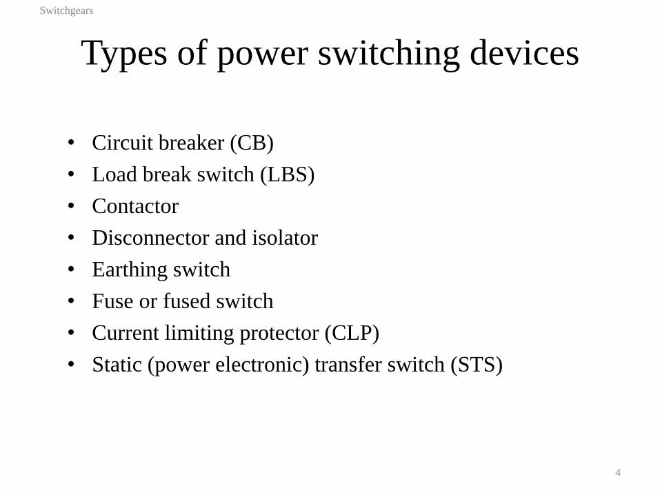
Types of power switching devices
• Circuit breaker (CB)
• Load break switch (LBS)
• Contactor
• Disconnector and isolator
• Earthing switch
• Fuse or fused switch
• Current limiting protector (CLP)
• Static (power electronic) transfer switch (STS)
Switchgears
4
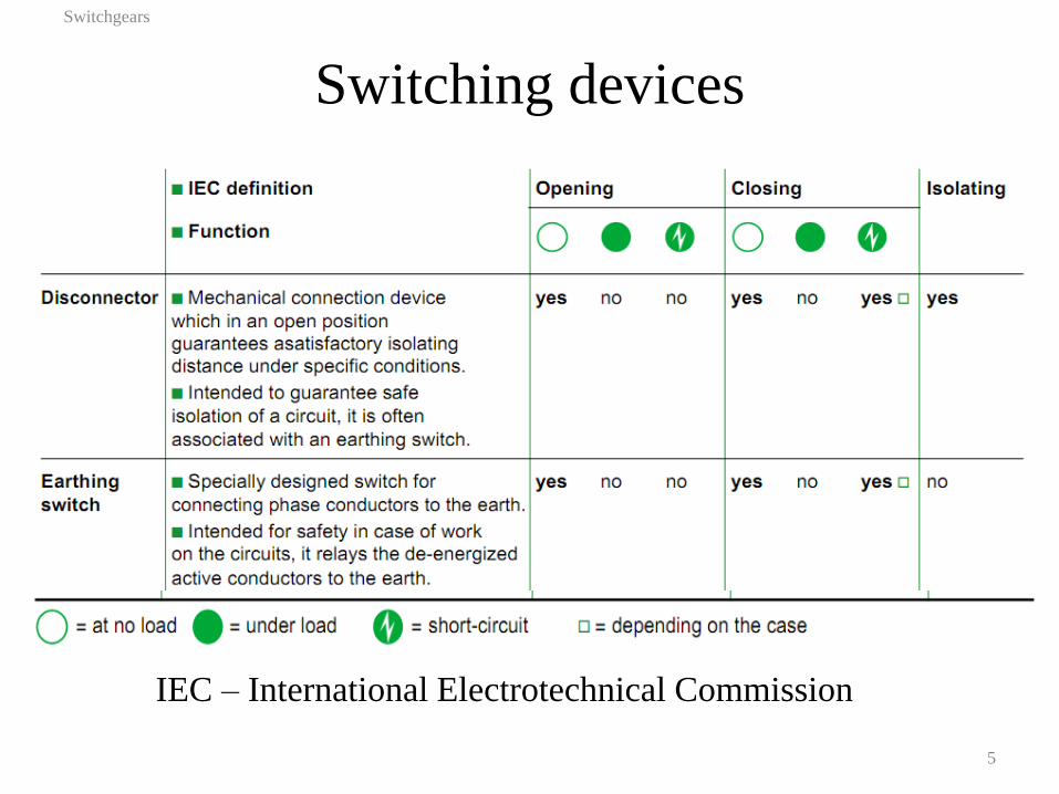
Switching devices
Switchgears
5
IEC – International Electrotechnical Commission
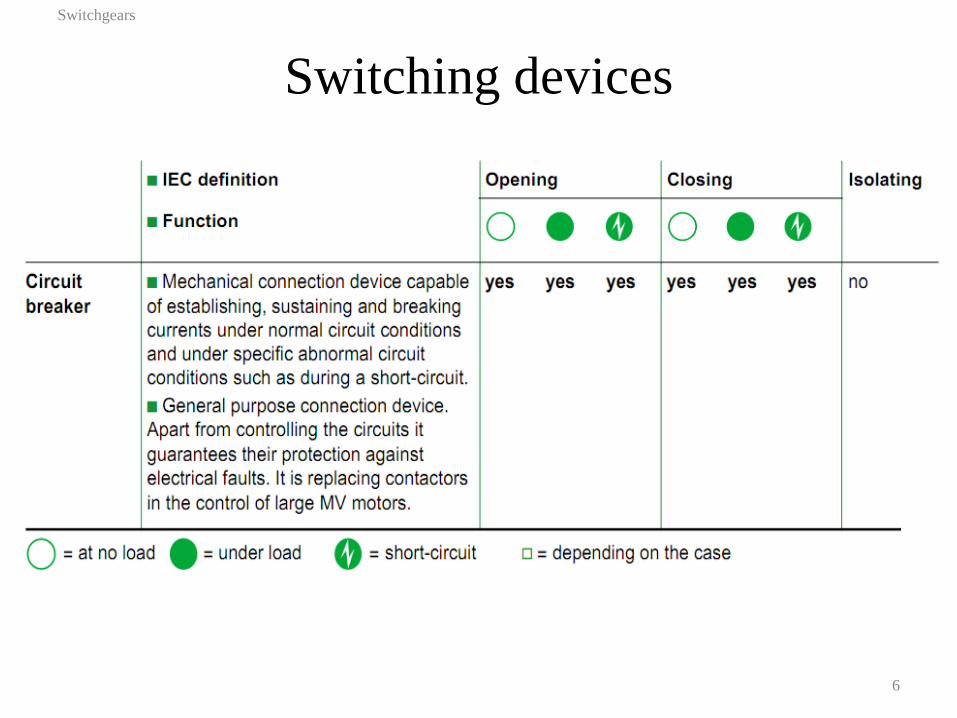
Switching devices
Switchgears
6
Power switching devices
• Mechanical switching devices or fuses in medium voltage (up to 33 kV) and high voltage circuits (66 kV and above)
• Solid-state power electronic switching as a special application (high speed load transfer and unlimited number of switching operations)
• Components of mechanical CB or LBS:
– a set of separable contacts
– a high speed operating mechanism (20 – 100 ms)
– electrical actuator to open (trip) or close the contacts
– arc extinguishing medium and chamber
– electrical insulation to withstand operating voltages
– connecting terminals
Switchgears
7

Current interruption
• Arc is drawn when contacts separate
• Arc will extinguishes at current zero-crossing
• Arc will reignite right after the zero-crossing as the voltage builds up
• Arc has to be extinguished to interrupt current
Switchgears
8
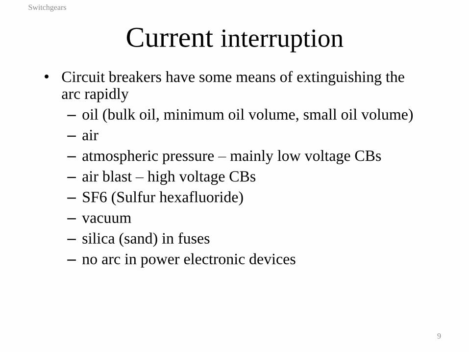
Current interruption
• Circuit breakers have some means of extinguishing the arc rapidly
– oil (bulk oil, minimum oil volume, small oil volume)
– air
– atmospheric pressure – mainly low voltage CBs
– air blast – high voltage CBs
– SF6 (Sulfur hexafluoride)
– vacuum
– silica (sand) in fuses
– no arc in power electronic devices
Switchgears
9
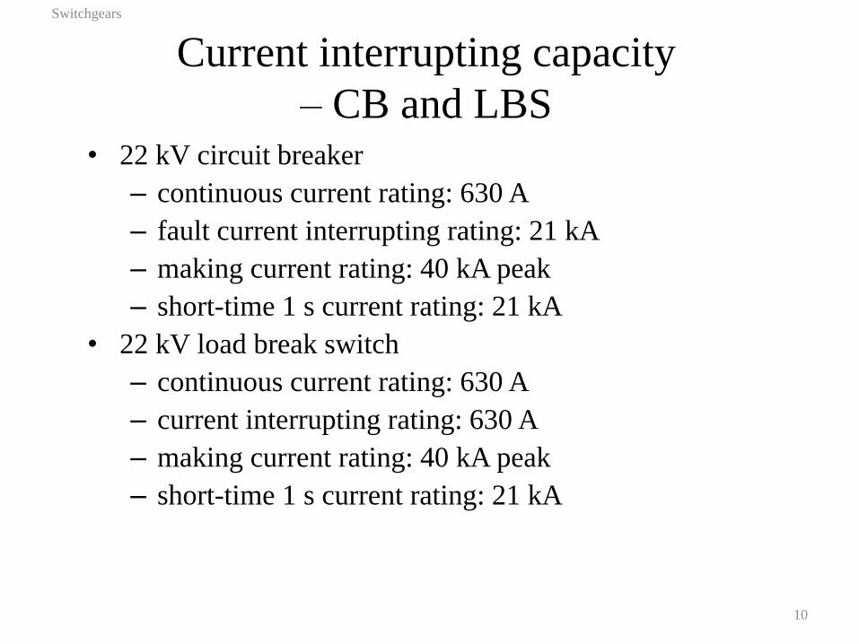
Current interrupting capacity
– CB and LBS • 22 kV circuit breaker
– continuous current rating: 630 A
– fault current interrupting rating: 21 kA
– making current rating: 40 kA peak
– short-time 1 s current rating: 21 kA
• 22 kV load break switch
– continuous current rating: 630 A
– current interrupting rating: 630 A
– making current rating: 40 kA peak
– short-time 1 s current rating: 21 kA
Switchgears
10
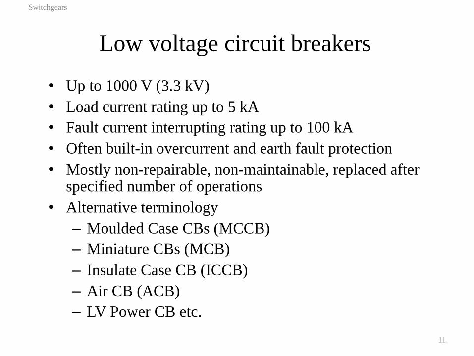
Low voltage circuit breakers
• Up to 1000 V (3.3 kV)
• Load current rating up to 5 kA
• Fault current interrupting rating up to 100 kA
• Often built-in overcurrent and earth fault protection
• Mostly non-repairable, non-maintainable, replaced after specified number of operations
• Alternative terminology
– Moulded Case CBs (MCCB)
– Miniature CBs (MCB)
– Insulate Case CB (ICCB)
– Air CB (ACB)
– LV Power CB etc.
Switchgears
11
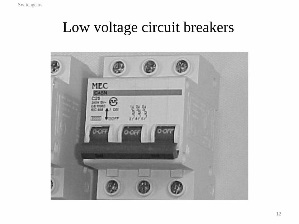
Low voltage circuit breakers
Switchgears
12

LV CBs – breaking in air
Switchgears
13
• Breaking chamber divided by refractory
panels forming arc chutes.
• Arc pushed into chutes by electrodynamic and
thermodynamic forces.
– Insulating plates: arc lengthened within
chutes to achieve maximum length near
current zero-crossing.
– Metal plates: arc divided into short arcs to
maximize voltage drop.
• Arc cools on contact with the refractory
material.
• Cooling and lengthening/dividing increases
arcing voltage.
• Breaking insulation achieved when Varc >
TRV
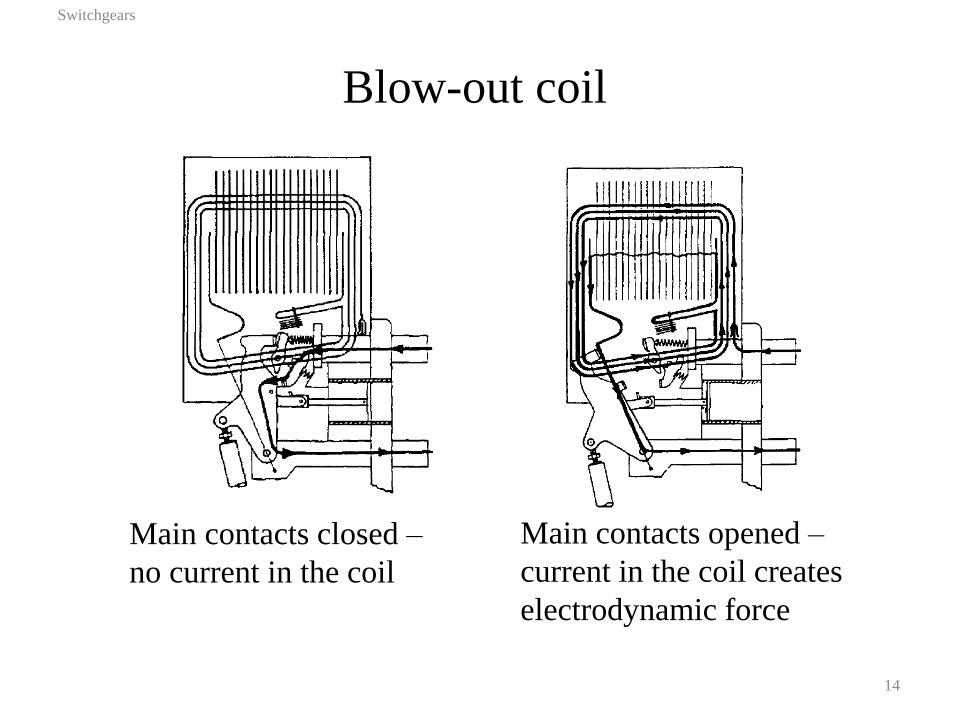
Blow-out coil
Switchgears
14
Main contacts closed –
no current in the coil
Main contacts opened –
current in the coil creates
electrodynamic force
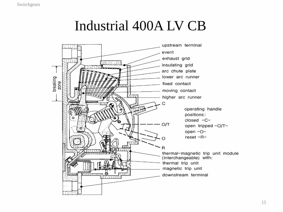
Industrial 400A LV CB
Switchgears
15
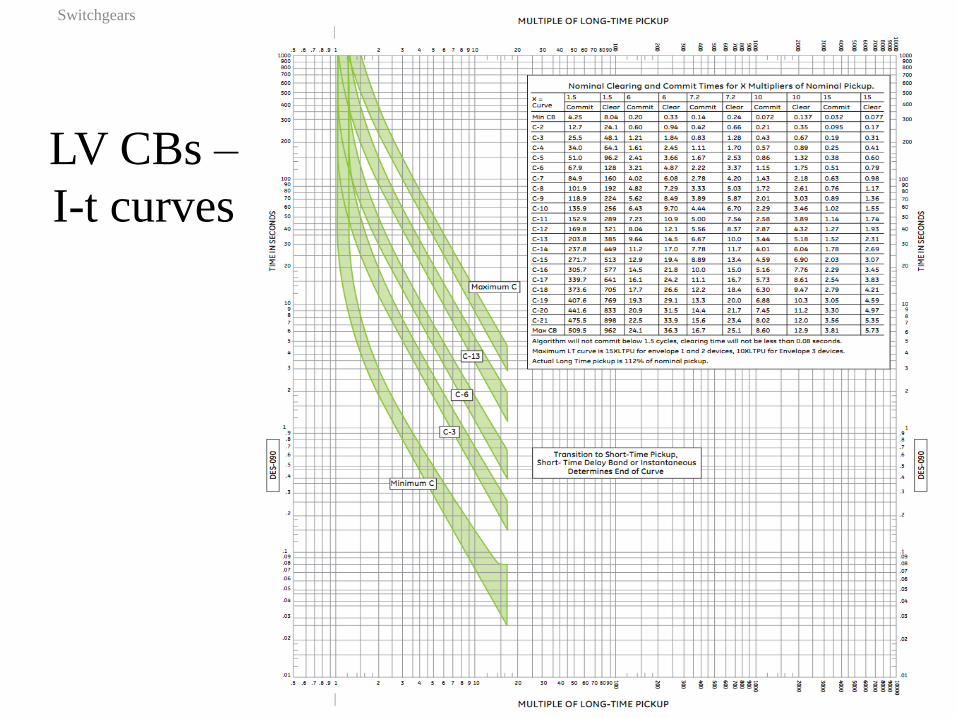
LV CBs –
I-t curves
Switchgears
16
High voltage circuit breakers
Switchgears
17
Designed to operate at voltages above 6.6 kV (up to 1,000
kV).
High transient recovery voltages demand fast restoration of
contact insulation. This requires presence of arc interruption
media
• Bulk oil (high oil volume)
• Minimum oil volume (low oil volume, small oil
volume)
• Air blast
• SF6
• Vacuum
Bulk oil circuit breakers
Switchgears
18
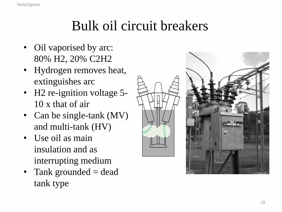
• Oil vaporised by arc:
80% H2, 20% C2H2
• Hydrogen removes heat,
extinguishes arc
• H2 re-ignition voltage 5-
10 x that of air
• Can be single-tank (MV)
and multi-tank (HV)
• Use oil as main
insulation and as
interrupting medium
• Tank grounded = dead
tank type
Bulk oil CB – simple arc pot
Switchgears
19
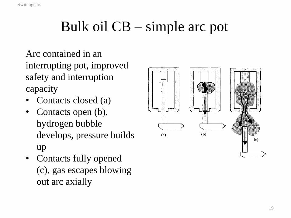
Arc contained in an
interrupting pot, improved
safety and interruption
capacity
• Contacts closed (a)
• Contacts open (b),
hydrogen bubble
develops, pressure builds
up
• Contacts fully opened
(c), gas escapes blowing
out arc axially
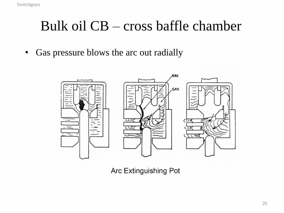
Bulk oil CB – cross baffle chamber
Switchgears
20
• Gas pressure blows the arc out radially
Minimum oil CBs
Switchgears
21
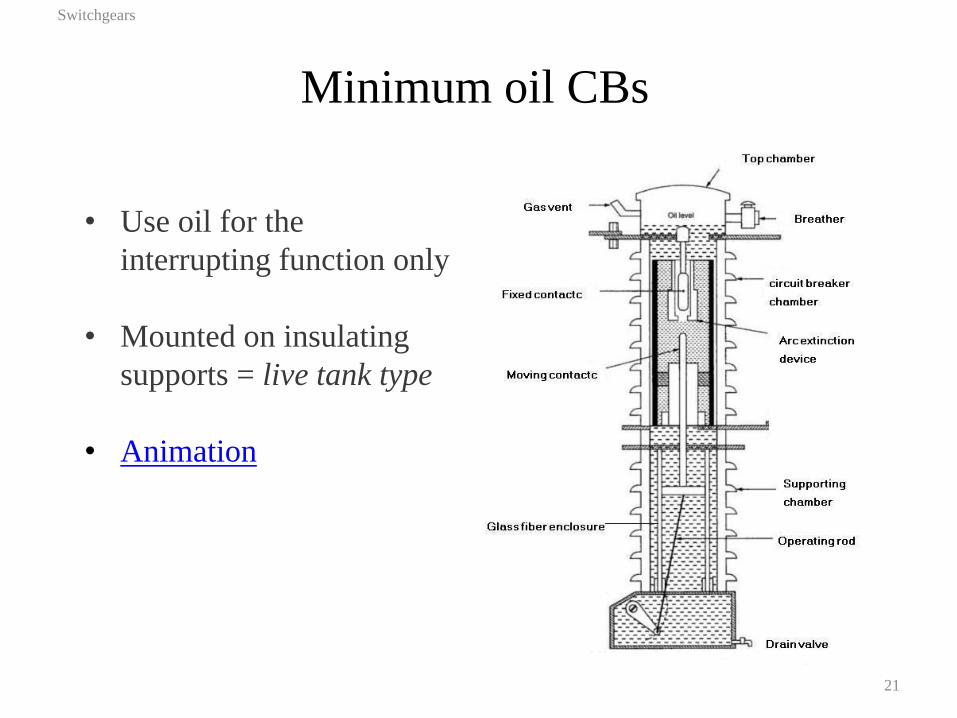
• Use oil for the
interrupting function only
• Mounted on insulating
supports = live tank type
• Animation
Oil CBs - disadvantages
Switchgears
22
• Inflammable medium – risk of fire
• Risk of explosion in contact with air
• High maintenance (oil testing, refilling)
• Impact on the environment if leaks
• Oil waste
SF6 in a circuit breaker
Switchgears
23
• Used from 3 kV up, almost exclusive above 66 kV
• Chemically stable, non-corrosive, non-poisonous,
odourless, colourless at room temperature
• Excellent dielectric and heat transfer properties
• Low dissociation temperature and high dissociative energy
(good for arc quenching)
• Recovers dielectric strength quickly after exposure to arc
• By-products of arced SF6 + moisture = corrosive
electrolytes (compatible materials must be used,
neutralised using lime or sodium carbonate and
bicarbonate)
• Most potent greenhouse agent
• Must be contained and recycled
SF6 circuit breaker
Switchgears
24
• Two types of interruption
o puffer: pressure is created by the mechanism
o self-blast (auto-puffer): pressure created by arc
• Two types of constructions
o dead tank
o live tank

Puffer type interrupter
Switchgears
25
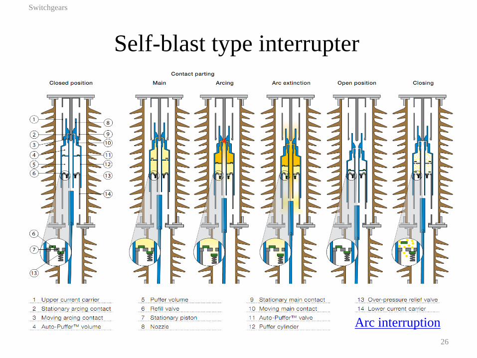
Self-blast type interrupter
Switchgears
26
Arc interruption
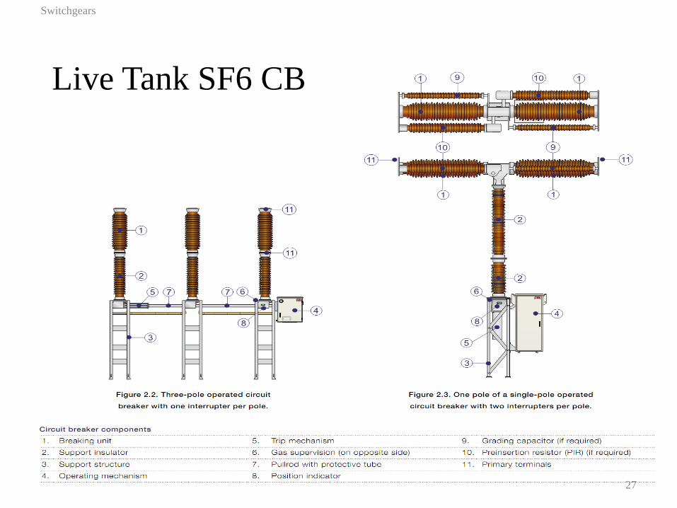
Live Tank SF6 CB
Switchgears
27
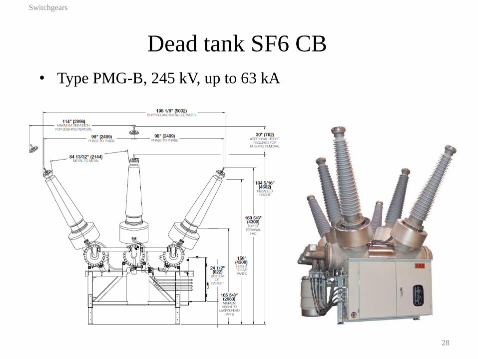
Dead tank SF6 CB
Switchgears
28
• Type PMG-B, 245 kV, up to 63 kA
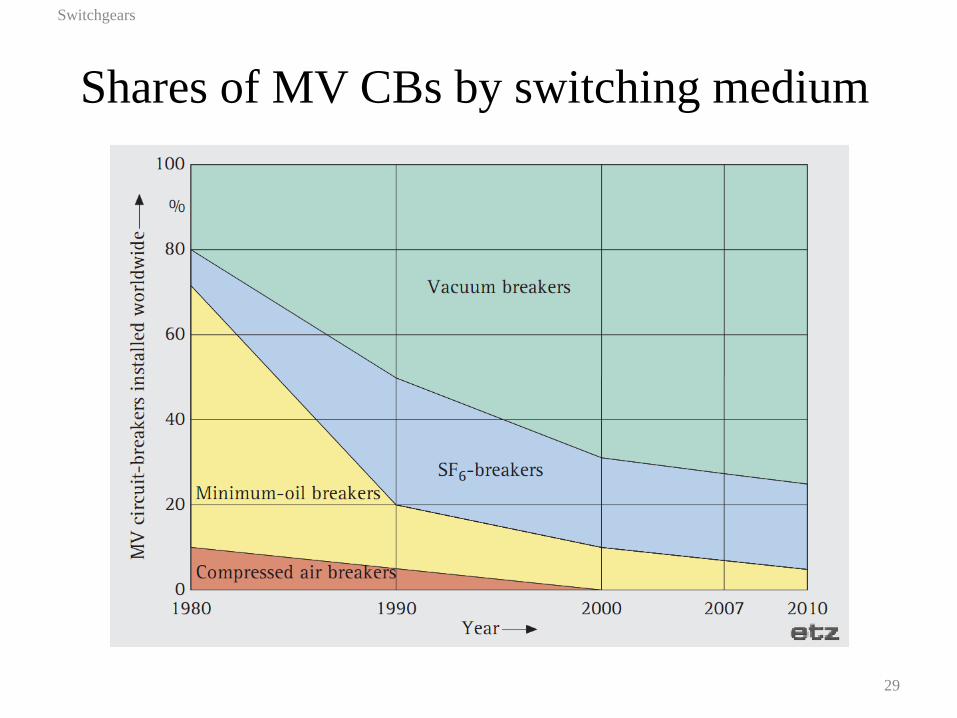
Shares of MV CBs by switching medium
Switchgears
29
Power vacuum circuit breakers
Switchgears
30
• Superior dielectric strength of vacuum
• Super-clean production environment required
• Diffuse-mode arc develops because of molten metals
from cathode spots
• Anode spots appear above 15 kA contributing to arc
• Magnetic field from current is utilised to keep arc in
diffuse state
–transverse field spirals arc on the contact surface
–axial arc spreads arc though the contact surface
• Contact material and construction is critical for the
performance
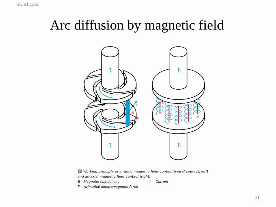
Arc diffusion by magnetic field
Switchgears
31
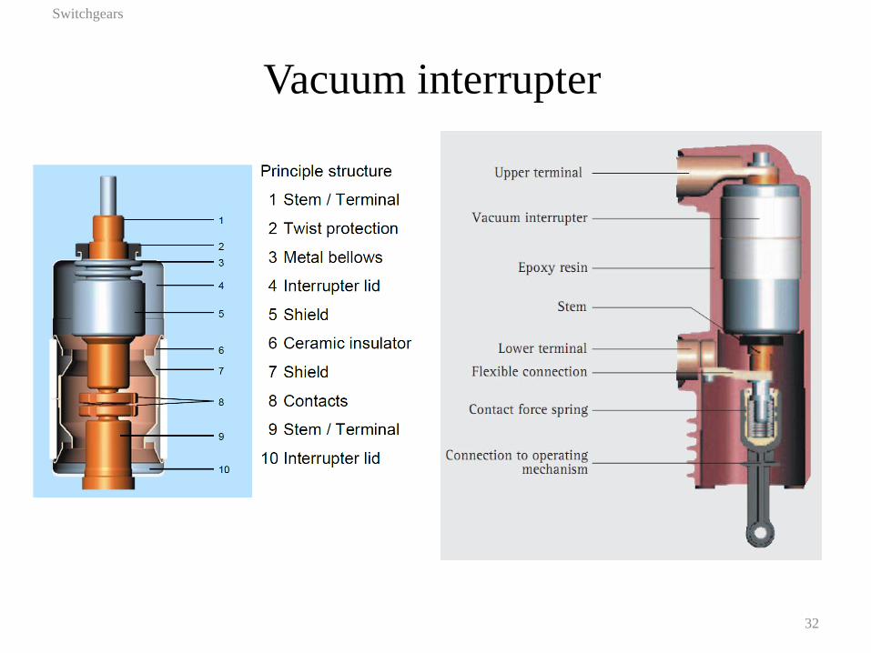
Vacuum interrupter
Switchgears
32

Vacuum interrupter in a circuit breaker
Switchgears
33
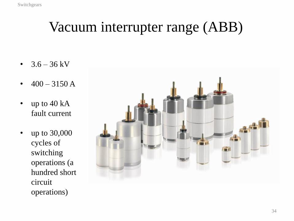
Vacuum interrupter range (ABB)
Switchgears
34
• 3.6 – 36 kV
• 400 – 3150 A
• up to 40 kA
fault current
• up to 30,000
cycles of
switching
operations (a
hundred short
circuit
operations)
Vacuum circuit breakers
Switchgears
35
• Compact design
• No impact on the environment
• Very low maintenance, easy to replace
• Lightweight, low energy mechanism
• Inherent apparent insensitivity to high
rate of TRV
• Fast interruption (within half a cycle)
• Limited voltage range (72.5 kV)
• Current chopping can be a problem
Switchgear Summary
Switchgears
36
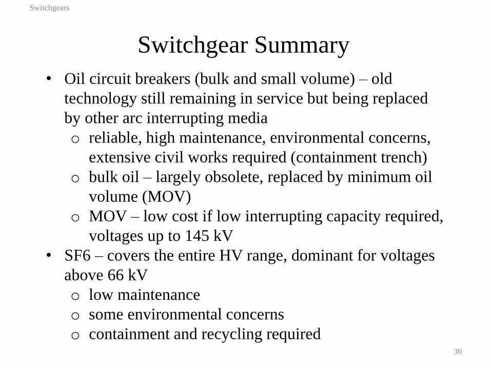
• Oil circuit breakers (bulk and small volume) – old
technology still remaining in service but being replaced
by other arc interrupting media
o reliable, high maintenance, environmental concerns,
extensive civil works required (containment trench)
o bulk oil – largely obsolete, replaced by minimum oil
volume (MOV)
o MOV – low cost if low interrupting capacity required,
voltages up to 145 kV
• SF6 – covers the entire HV range, dominant for voltages
above 66 kV
o low maintenance
o some environmental concerns
o containment and recycling required
Switchgear Summary
Switchgears
37
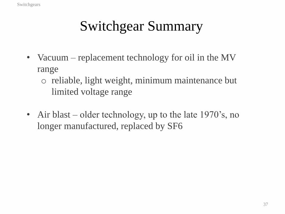
• Vacuum – replacement technology for oil in the MV
range
o reliable, light weight, minimum maintenance but
limited voltage range
• Air blast – older technology, up to the late 1970’s, no
longer manufactured, replaced by SF6

Outline
• Introduction to power switchgear
• AC Power Network Switching Duties (optional)
• Circuit breaker and fuse selection (Sect 7.5 Text)
Switchgears
38

Ideal Characteristics
Switchgears
39
• From an electrical point of view the ideal characteristics
of an AC circuit breaker are:
• Zero resistance when closed, or passing currents
• Infinite resistance when open
• Smooth transition between these states at a natural
current zero
• Of these points, the last is the most difficult to obtain and
in practice is not fully achieved in any existing switch or
high voltage circuit breaker.
AC Interruption Basics - 1
Switchgears
40
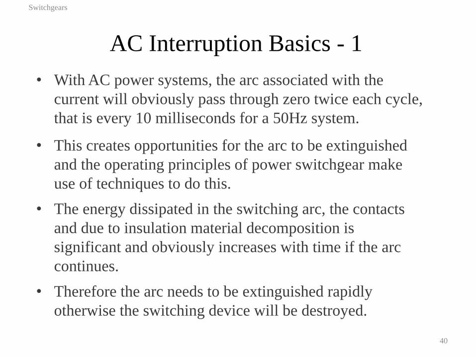
• With AC power systems, the arc associated with the
current will obviously pass through zero twice each cycle,
that is every 10 milliseconds for a 50Hz system.
• This creates opportunities for the arc to be extinguished
and the operating principles of power switchgear make
use of techniques to do this.
• The energy dissipated in the switching arc, the contacts
and due to insulation material decomposition is
significant and obviously increases with time if the arc
continues.
• Therefore the arc needs to be extinguished rapidly
otherwise the switching device will be destroyed.
AC Interruption Basics - 2
Switchgears
41
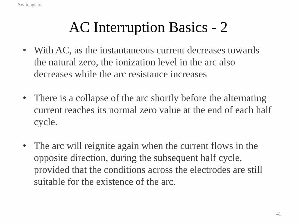
• With AC, as the instantaneous current decreases towards
the natural zero, the ionization level in the arc also
decreases while the arc resistance increases
• There is a collapse of the arc shortly before the alternating
current reaches its normal zero value at the end of each half
cycle.
• The arc will reignite again when the current flows in the
opposite direction, during the subsequent half cycle,
provided that the conditions across the electrodes are still
suitable for the existence of the arc.
AC Interruption Basics - 2
Switchgears
42
• The transition time between the two half cycles is greatly
influenced by the medium in which the arc is being
produced and by the characteristics of the external
electrical circuit.
Circuit Breaker Arc Extinguishing Medium
Switchgears
43
• Air
• SF6 gas
• Vacuum
• Mineral insulating oil
AC Current Switching – Arc Voltage
Switchgears
44
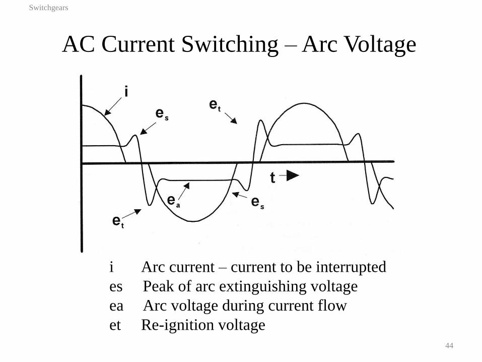
i Arc current – current to be interrupted
es Peak of arc extinguishing voltage
ea Arc voltage during current flow
et Re-ignition voltage
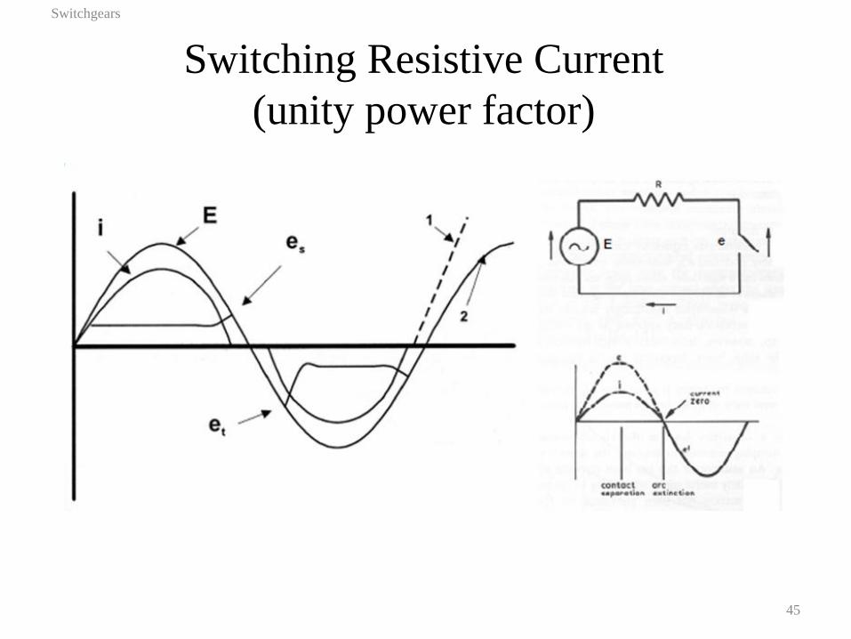
Switching Resistive Current
(unity power factor)
Switchgears
45
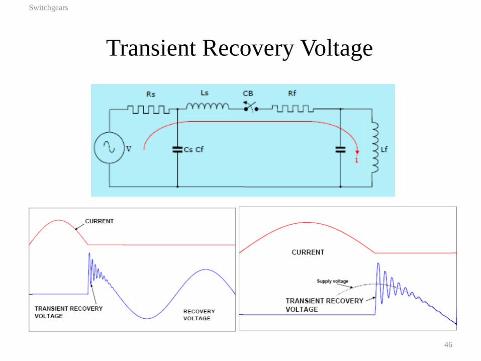
Transient Recovery Voltage
Switchgears
46
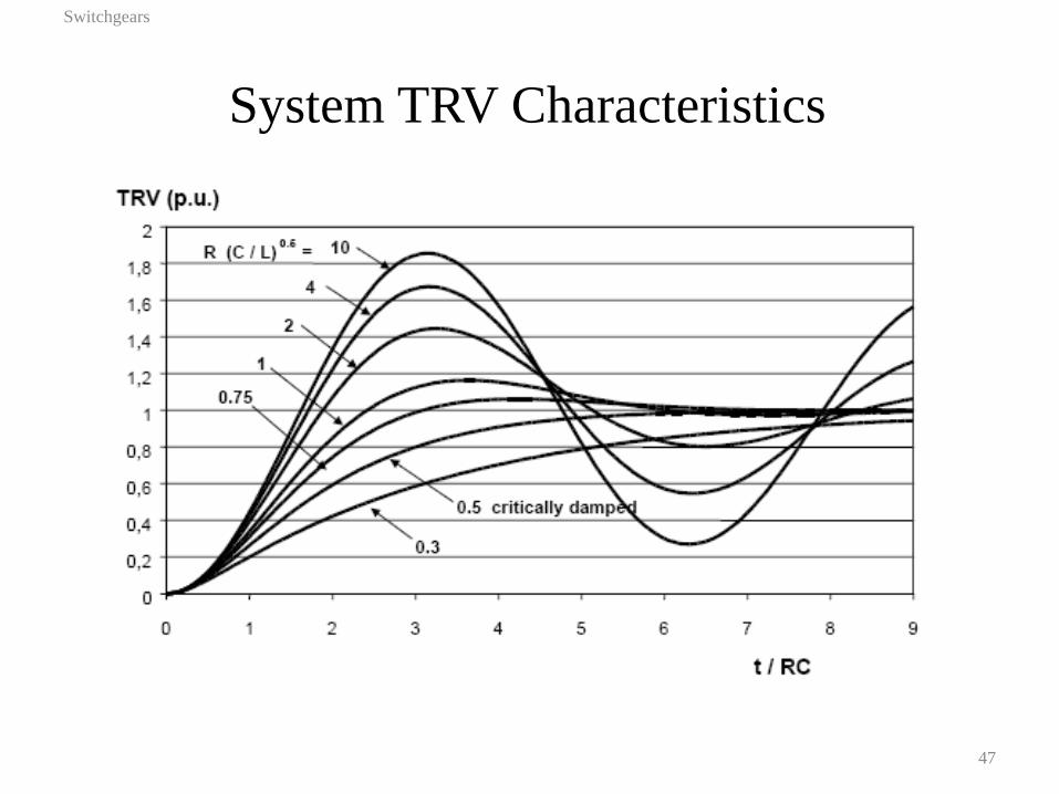
System TRV Characteristics
Switchgears
47
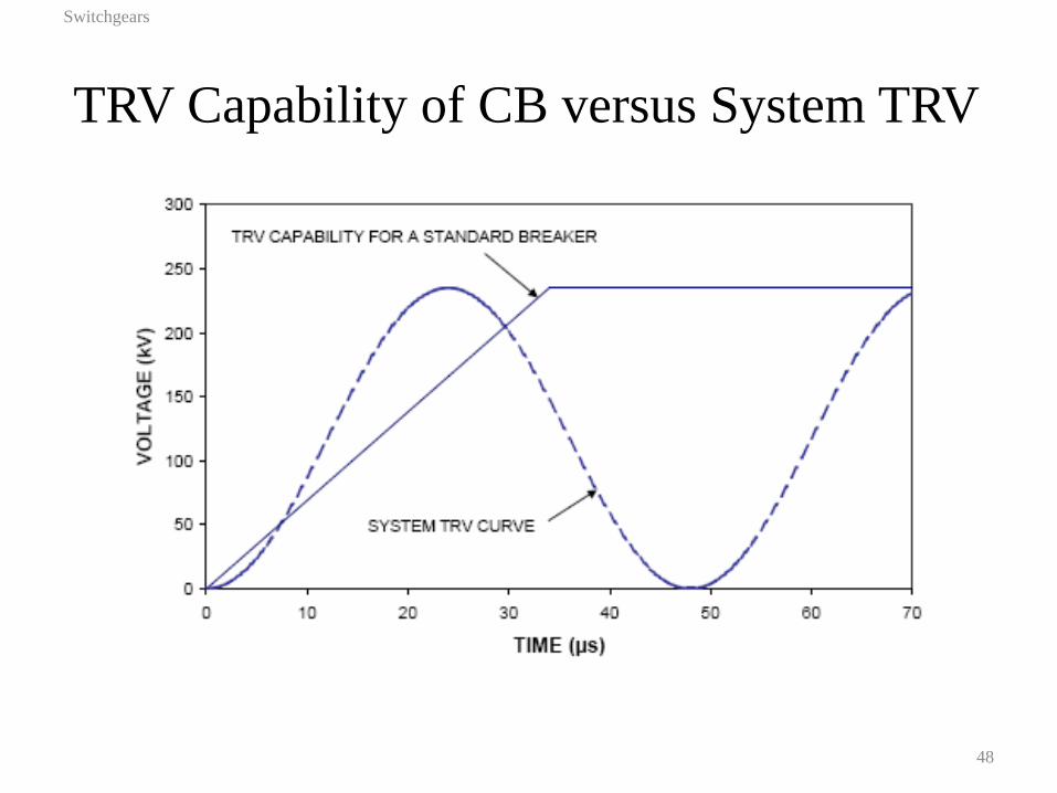
TRV Capability of CB versus System TRV
Switchgears
48
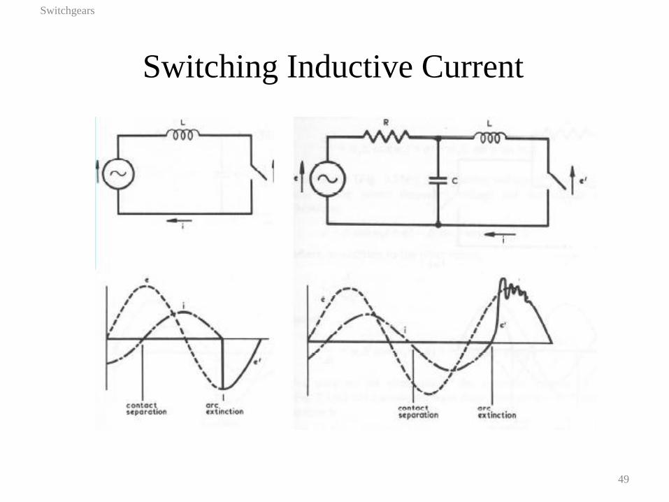
Switching Inductive Current
Switchgears
49

Switching Inductive Current
Switchgears
50
Breaking Small Inductive Currents
Switchgears
51
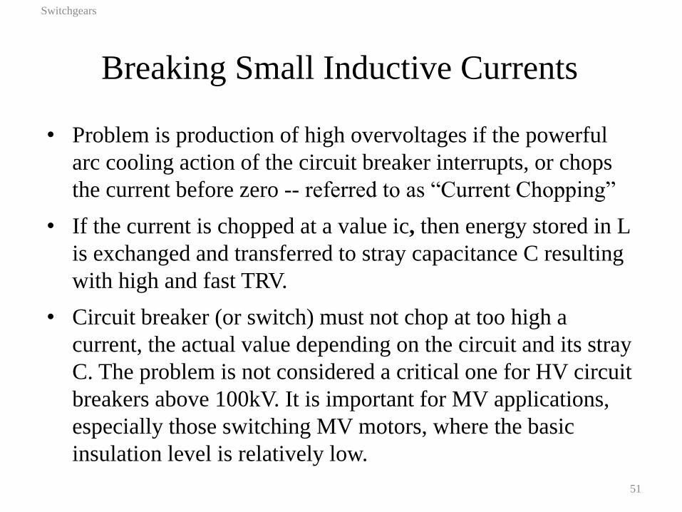
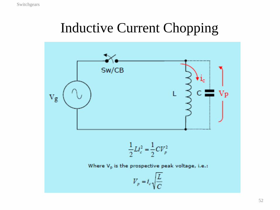
• Problem is production of high overvoltages if the powerful
arc cooling action of the circuit breaker interrupts, or chops
the current before zero -- referred to as “Current Chopping”
• If the current is chopped at a value ic, then energy stored in L
is exchanged and transferred to stray capacitance C resulting
with high and fast TRV.
• Circuit breaker (or switch) must not chop at too high a
current, the actual value depending on the circuit and its stray
C. The problem is not considered a critical one for HV circuit
breakers above 100kV. It is important for MV applications,
especially those switching MV motors, where the basic
insulation level is relatively low.
Inductive Current Chopping
Switchgears
52
Current Chopping
Switchgears
53
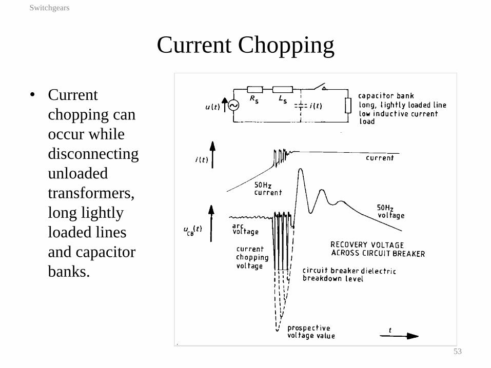
• Current
chopping can
occur while
disconnecting
unloaded
transformers,
long lightly
loaded lines
and capacitor
banks.
Switching Capacitive Current
Switchgears
54
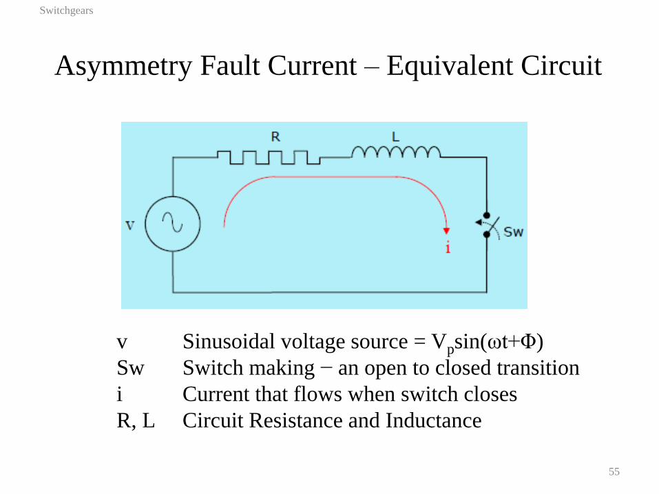
Asymmetry Fault Current – Equivalent Circuit
Switchgears
55
v Sinusoidal voltage source = Vpsin(ωt+Φ)
Sw Switch making − an open to closed transition
i Current that flows when switch closes
R, L Circuit Resistance and Inductance
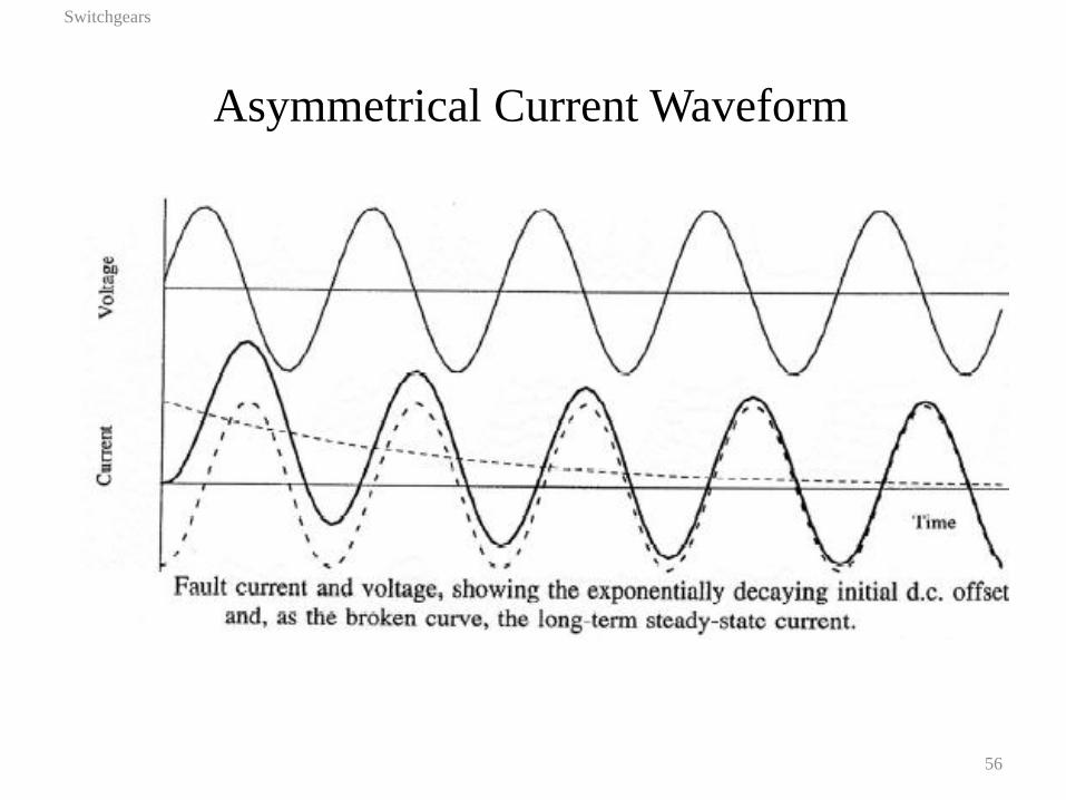
Asymmetrical Current Waveform
Switchgears
56
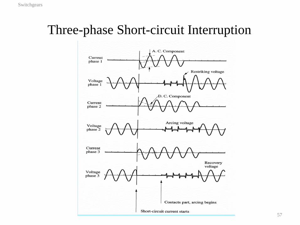
Three-phase Short-circuit Interruption
Switchgears
57
Switching Duties Summary
Switchgears
58
In practice, each item of switchgear must be capable of a
great variety of switching operations:
• Short-circuit fault interruption. Often the most
demanding duty.
• Short-circuit fault making. Peak current required.
• Load-break duty. Often the least demanding duty but
more frequent.
• Capacitor switching. Gives a high recovery voltage an
can lead to re-striking.
• Line-dropping duty. Very similar to capacitive switching
but can produce higher peak voltages.
Switching Duties Summary
Switchgears
59
• Inductive switching at low currents. This duty can
produce current chopping leading to very high
overvoltages. It can be found with no-load transformer
switching and the switching of inrush currents, reactor
and motor switching.
• Asynchronous switching of two parts of a system. This
duty is associated with fault currents of modest
magnitude but with high peak voltages.
Switching Duties Summary
Switchgears
60
• Evolving faults. Where the current to be interrupted is
initially small and increases to a large value during
interruption. This duty has diminished in importance
with the advent of gas and particularly SF6 blast circuit
breakers. It was of especial importance with oil circuit
breakers where the sudden increase of current could lead
to explosion.
Switching Duties Summary
Switchgears
61
• Parallel switching. Here the switching duty involves two
circuit breakers, one each in a pair of parallel paths. One
path has a higher impedance than the second but is
slower to interrupt. The faster circuit breaker interrupts
leaving all of the current to be taken by the second. This
is a fault of the same kind as the evolving fault but
usually less extreme.

Outline
• Introduction to power switchgear
• AC Power Network Switching Duties (optional)
• Circuit breaker and fuse selection (Sect 7.5 Text)
Switchgears
62
Circuit Breaker Selection
Switchgears
63
• Modern circuit breaker (CB) standards are based on
symmetrical interrupting current
• It is usually necessary to calculate only symmetrical fault
current at a system location, and then select a CB with a
symmetrical interrupting capability equal to or above the
calculated current
• The maximum symmetrical short-circuit (SSC) current at
the system location in question is calculated from the
prefault voltage and system reactance characteristics
• For X/R (ratio) ≥ 15, the calculated current at the given
operating voltage is used to select CB capacity, otherwise
20% of extra margin is added to CB capacity

Switchgears
64
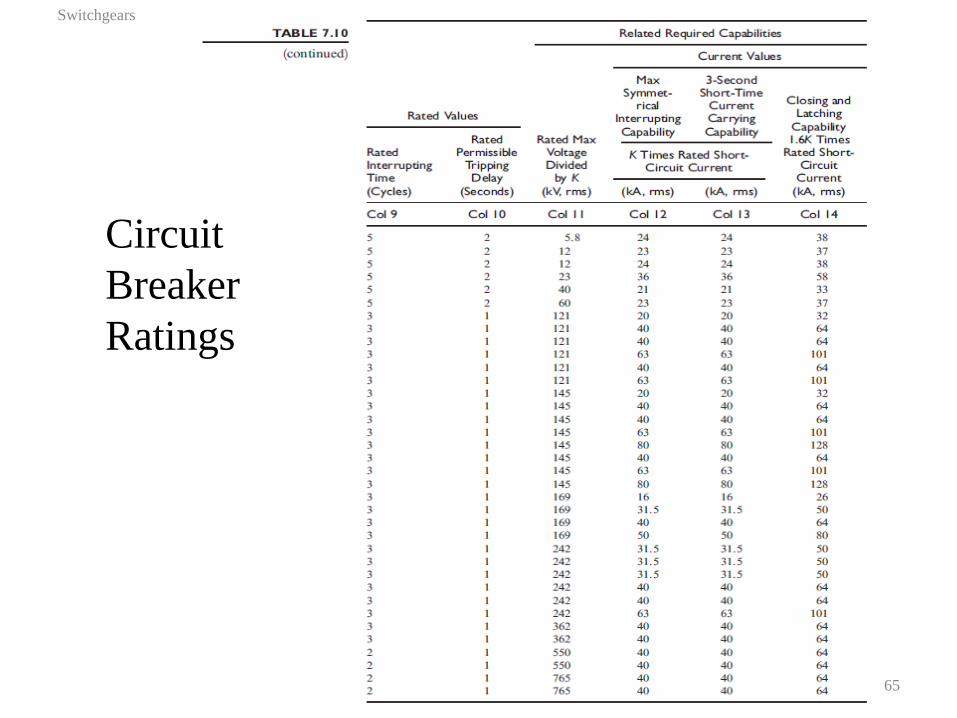
Circuit
Breaker
Ratings
*
Switchgears
65
Circuit
Breaker
Ratings
Circuit Breaker Ratings Example
Switchgears
66
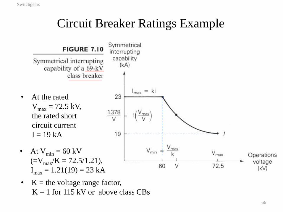
• At Vmin = 60 kV
(=Vmax/K = 72.5/1.21),
Imax = 1.21(19) = 23 kA
• K = the voltage range factor,
K = 1 for 115 kV or above class CBs
• At the rated
Vmax = 72.5 kV,
the rated short
circuit current
I = 19 kA
Circuit Breaker Selection Example
Switchgears
67
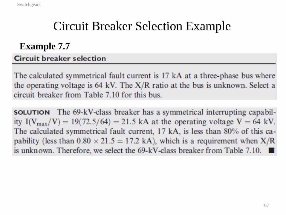
Example 7.7
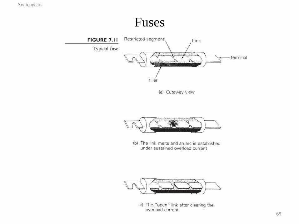
Fuses
Switchgears
68
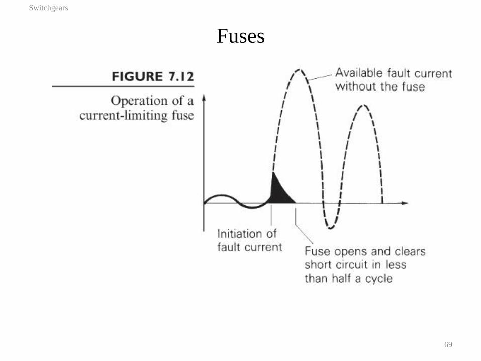
Fuses
Switchgears
69
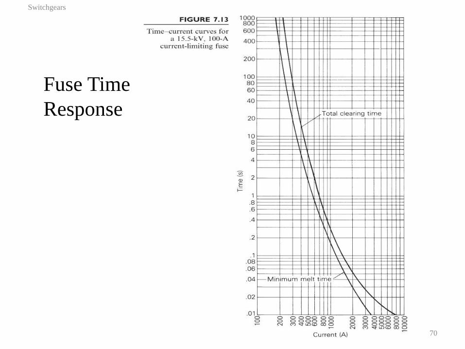
Fuse Time
Response
Switchgears
70