Embed Size (px)
Citation preview
GE EnergyDigital Energy
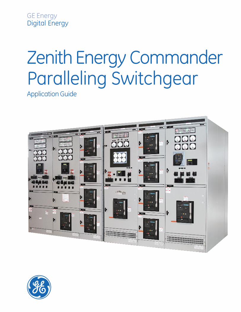
Zenith Energy CommanderParalleling SwitchgearApplication Guide

• Flexibility
• IncreasedReliability
• UninterruptibleMaintenance
• Cost Savings
• Scalability
• Proven Experience
• World-Class Global Service
Information contained in this application guide is basedon established industry standards and practices. It ispublished in the interest of assisting in the preparation ofplans and specifications for medium and low voltageparalleling switchgear. Neither the General Electric Companynor any person acting on its behalf assumes any liabilitywith respect to the use of, or for damages or injuryresulting from the use of any information contained inthis application guide. This guide should be considered asupplement and should be used in conjunction with the GESwitchgear medium and low voltage application guides.
Introduction
Paralleling is an operation in which multiplepower sources, usually two or more generatorsets, are connected and synchronized to acommon bus (same parameters in regardsto frequency, phase angle, etc.).
Why Zenith Energy Commander?
Zenith Energy Commanderprovides customerfacilities with reliable power switching systems.Since the inception of paralleling switchgear(PSG), many successful Energy Commanderinstallations have been supplied with a focuson providing reliability.
Zenith Energy Commander has evolved andadapted to the changing technologies inengine generator design, switchgear controlsand monitoring systems. It reflects GE’scontinuing commitment to reliable solutionsfor critical power applications.
Why Parallel?
There are several advantages to employingPSG in an electrical design, such as flexibility,increased reliability, ease of uninterruptiblemaintenance and application/operation costsavings. It is because of these advantagesthat PSG has become one of the best choicesfor meeting today’s power requirements.
Flexibility
Paralleling power sources allows for a widevariety of choices in the generation, distribu-tion and utilization of the system’s power.
Increased Reliability
Systems in which part of the load is verycritical may be best served by parallelingone or more generator sets. Under paralleloperation all the generator sets are startedat once. The first set to reach the properparameters will assume the most criticalportion of the load, with the remaining setspicking up lower priority loads. In addition,by using a load shedding application, thefailure of one generator set will not interruptpower to the critical loads, as less criticalloads can be shed.
Uninterruptible Maintenance
When one engine - generator set is out ofservice for maintenance or repair, havingothers synchronized on the same bus canprovide the needed back-up power, shouldan outage occur.
Cost Savings and Scalability
Savings can be realized on the applicationwhen a number of smaller sets would beless expensive than one large set or whenthe load makes it impractical to divide intoseveral sections, each with it’s own generator.Also, when it is anticipated that the loadwill grow significantly in the future, thecapital investment can be reduced bystarting with small sets and parallelingadditional units as load increases dictate.
GE Energy – Digital Energy
Zenith Energy CommanderParalleling Switchgear
Emergency or Standby Power
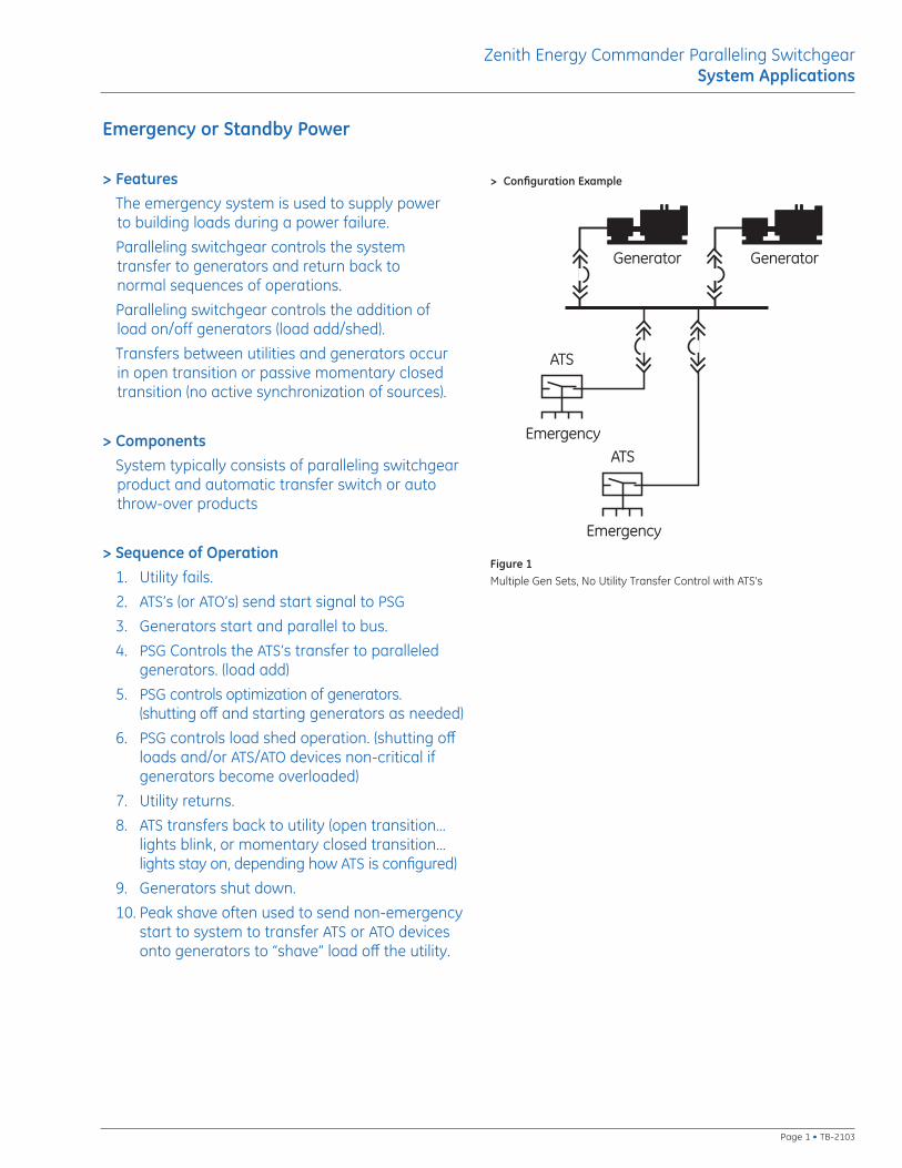
> FeaturesThe emergency system is used to supply power to building loads during a power failure.
Paralleling switchgear controls the system transfer to generators and return back to normal sequences of operations.
Paralleling switchgear controls the addition of load on/off generators (load add/shed).
Transfers between utilities and generators occur in open transition or passive momentary closedtransition (no active synchronization of sources).
> ComponentsSystem typically consists of paralleling switchgearproduct and automatic transfer switch or autothrow-over products
> Sequence of Operation1. Utility fails.
2. ATS’s (or ATO’s) send start signal to PSG
3. Generators start and parallel to bus.
4. PSG Controls the ATS’s transfer to paralleledgenerators. (load add)
5. PSG controls optimization of generators. (shutting off and starting generators as needed)
6. PSG controls load shed operation. (shutting offloads and/or ATS/ATO devices non-critical ifgenerators become overloaded)
7. Utility returns.
8. ATS transfers back to utility (open transition...lights blink, or momentary closed transition...lights stay on, depending how ATS is configured)
9. Generators shut down.
10. Peak shave often used to send non-emergencystart to system to transfer ATS or ATO devicesonto generators to “shave” load off the utility.
Generator Generator
Emergency
ATS
Emergency
ATS
Figure 1Multiple Gen Sets, No Utility Transfer Control with ATS’s
> Configuration Example
Page 1 • TB-2103
Zenith Energy Commander Paralleling SwitchgearSystem Applications
> Configuration Example
Prime Power
> FeaturesOn-site prime power systems are most often used where there is no utility source available.
The required electricity is generated entirely on-site,typically at facilities such as island resorts, mines,mills or other remote locations.
Since utility is not available in prime power systems,ATS’s/ATO’s and utility/tie breakers are not required.
> ComponentsGenerators are the only source of power. The system typically consists of PSG product with no ATS/ATO products.
> Sequence of Operation1. System enable signal causes generators
to start and parallel to bus.
2. PSG controls optimization of generators. (shutting off and starting generators as needed)
3. PSG controls load shed operation. (shutting off loads non-critical if generators become overloaded)
4. PSG controls frequency of generators for clock/time correction.
5. Removing system enable signal will shutdown the generators.
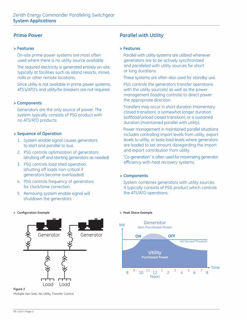
Figure 2Multiple Gen Sets, No Utility Transfer Control
Generator Generator
Load Load
Parallel with Utility
> FeaturesParallel with utility systems are utilized whenevergenerators are to be actively synchronized and paralleled with utility sources for short or long durations.
These systems are often also used for standby use.
PSG controls the generators transfer operationswith the utility source(s) as well as the power management (loading controls) to direct power the appropriate direction.
Transfers may occur in short duration (momentaryclosed transition), a somewhat longer duration(softload/unload closed transition), or a sustainedduration (maintained parallel with utility).
Power management in maintained parallel situationsincludes controlling import levels from utility, exportlevels to utility, or base load levels where generatorsare loaded to set amount disregarding the importand export contribution from utility.
“Co-generation” is often used for maximizing generatorefficiency with heat recovery systems.
> ComponentsSystem combines generators with utility sources. It typically consists of PSG product which controlsthe ATS/ATO operations.
10 2 4 6 88 12Noon
11 3 5 79 1
ON OFF
UtilityPurchased Power
GeneratorNon-Purchased Power
kW Demand Threshold
Time
kW
> Peak Shave Example
Zenith Energy Commander Paralleling SwitchgearSystem Applications
TB-2103 • Page 2
Utility
Generator Generator
Load Load
Utility
Generator Generator
Load Load
Utility
Load Load
Utility Utility
Generator Generator
Load Load Load Load
Utility
Generator Generator
Load Load
Sequence of Operation1. When used for standby, the PSG
operates in the same manner as the emergency standbysequence. If not used for standby,the generators remain offlinewhen utility is not present.
2. Non-emergency start signal is sentto PSG for peak shave or exportingpower to utility applications.
3. Generators start and parallel to busand with utility.
4. PSG controls the transfer of loadsoff the utility onto the generatorsin momentary closed transition (ifemergency standby is also utilized)or softload closed transition.
5. In maintained parallel with utilityapplications, the PSG controls theamount of import power from utility,export power to utility, or base loadsthe generators to a fixed amountnon-dependent upon the utility-supplied power. With emergencystandby applications not maintainingparalleling with utility, the PSG in thiscase controls the synchronizing ofgenerators with utility and momentaryclosed transition transfer onto thegenerator bus.
6. PSG controls optimization of gen-erators (shutting off and startinggenerators as needed).
7. PSG controls load shed operation ifemergency standby is also utilized.
8. Non-emergency start signal is removed.
9. PSG controls the soft unload ofgenerators off the utility or momen-tary closed transition from utility ifemergency standby is utilized.
10. Generators shut down.
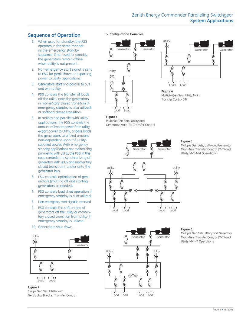
Figure 3Multiple Gen Sets, Utility andGenerator Main-Tie Transfer Control
> Configuration Examples
Figure 4Multiple Gen Sets, Utility Main Transfer Control (M)
Figure 6Multiple Gen Sets, Utility and GeneratorMain-Tie’s Transfer Control (M-T) andUtility M-T-M Operations
Figure 5Multiple Gen Sets, Utility and GeneratorMain-Tie’s Transfer Control (M-T) andUtility M-T-T-M Operations
Utility
Generator
Load Load
Figure 7Single Gen Set, Utility with Gen/Utility Breaker Transfer Control
Zenith Energy Commander Paralleling SwitchgearSystem Applications
Page 3 • TB-2103
Standby
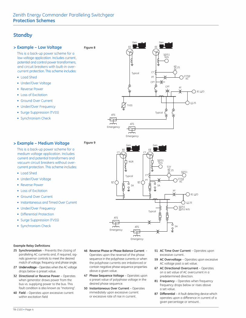
> Example – Low VoltageThis is a back-up power scheme for alow voltage application. Includes current,potential and control power transformers,and circuit breakers with built-in over-current protection. This scheme includes:
• Load Shed
• Under/Over Voltage
• Reverse Power
• Loss of Excitation
• Ground Over Current
• Under/Over Frequency
• Surge Suppression (TVSS)
• Synchronism Check
Gen Gen
50/51N/G
4032
25
27/5981
CT
PT
Typical
Typical
LS 25
81 U/O
EE EE
Emergency
ATS
PT
CPT
CPT
TVSS
Emergency
ATS
> Example – Medium VoltageThis is a back-up power scheme for amedium voltage application. Includescurrent and potential transformers andvacuum circuit breakers without over-current protection. This scheme includes:
• Load Shed
• Under/Over Voltage
• Reverse Power
• Loss of Excitation
• Ground Over Current
• Instantaneous and Timed Over Current
• Under/Over Frequency
• Differential Protection
• Surge Suppression (TVSS)
• Synchronism Check
Gen Gen
50/51N/G
51V4032
2550/51
27/5981
CT
PT
NGR
SA
Typical
87
CT
Typical
50/5150/51 N/G
LS 25
81 U/O
SA
EE EE
Emergency
ATS
PT
Emergency
ATS
SA87
CT
Example Relay Definitions25 Synchronization – Prevents the closing of
paralleling AC currents and, if required, sig-nals governor controls to meet the desiredmatch of voltage, frequency and phase angle.
27 Undervoltage – Operates when the AC voltagedrops below a preset value.
32 Directional or Reverse Power – Operateswhen generator draws power from thebus vs. supplying power to the bus. Thisfault condition is also known as “motoring”.
40 Field – Operates upon excessive currentwithin excitation field
46 Reverse Phase or Phase Balance Current –Operates upon the reversal of the phasesequence in the polyphase currents or whenthe polyphase currents are imbalanced orcontain negative phase sequence propertiesabove a given value.
47 Phase Sequence Voltage – Operates upona preset value of polyphase voltage in thedesired phase sequence.
50 Instantaneous Over Current – Operatesimmediately upon excessive currentor excessive rate of rise in current.
51 AC Time Over Current – Operates uponexcessive current.
59 AC Overvoltage – Operates upon excessiveAC voltage past a set value.
67 AC Directional Overcurrent – Operateson a set value of AC overcurrent in apredetermined direction.
81 Frequency – Operates when frequencyfrequency drops below or rises abovea set value.
87 Differential – A fault detecting device whichoperates upon a difference in current of agiven percentage or amount.
Figure 8
Figure 9
Zenith Energy Commander Paralleling SwitchgearProtection Schemes
TB-2103 • Page 4
Parallel with Utility
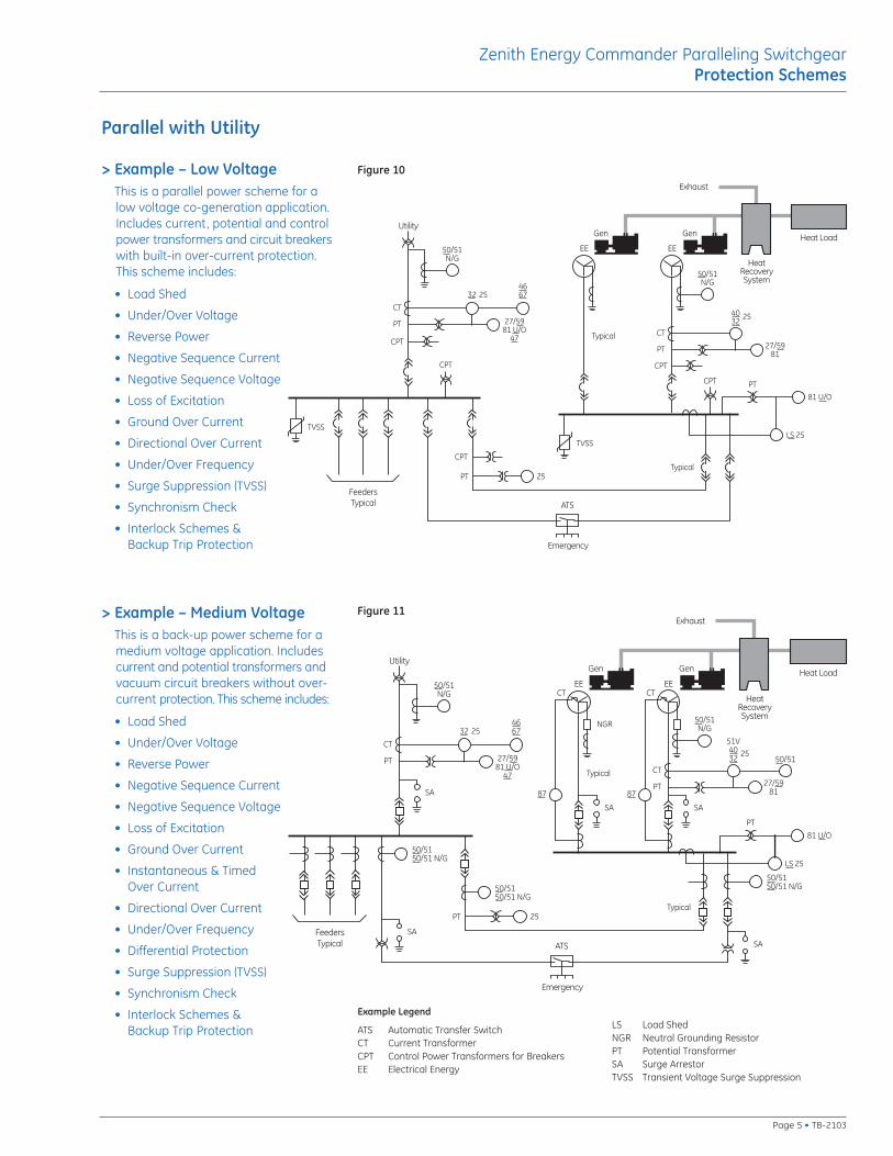
> Example – Low VoltageThis is a parallel power scheme for alow voltage co-generation application.Includes current, potential and controlpower transformers and circuit breakerswith built-in over-current protection.This scheme includes:
• Load Shed
• Under/Over Voltage
• Reverse Power
• Negative Sequence Current
• Negative Sequence Voltage
• Loss of Excitation
• Ground Over Current
• Directional Over Current
• Under/Over Frequency
• Surge Suppression (TVSS)
• Synchronism Check
• Interlock Schemes & Backup Trip Protection
> Example – Medium VoltageThis is a back-up power scheme for amedium voltage application. Includescurrent and potential transformers andvacuum circuit breakers without over-current protection. This scheme includes:
• Load Shed
• Under/Over Voltage
• Reverse Power
• Negative Sequence Current
• Negative Sequence Voltage
• Loss of Excitation
• Ground Over Current
• Instantaneous & Timed Over Current
• Directional Over Current
• Under/Over Frequency
• Differential Protection
• Surge Suppression (TVSS)
• Synchronism Check
• Interlock Schemes & Backup Trip Protection
HeatRecoverySystem
Heat Load
Exhaust
Gen Gen
50/51N/G
4032
25
27/5981
CT
PT
Typical
Typical
LS 25
81 U/O
EE EE
25PT
Emergency
ATS
Utility
CT
PT
32 254667
27/5981 U/O
47
50/51N/G
FeedersTypical
PT
CPT
CPT
CPT
CPT
CPT
TVSS
TVSS
HeatRecoverySystem
Heat Load
Exhaust
Gen Gen
50/51N/G
51V4032
2550/51
27/5981
CT
PT
NGR
SA
Typical
87
CT
Typical
50/5150/51 N/G
LS 25
81 U/O
SA
EE EE
50/5150/51 N/G
25PT
50/5150/51 N/G
SA
Emergency
ATS
Utility
SA
CT
PT
32 254667
27/5981 U/O
47
50/51N/G
FeedersTypical
PT
SA
87
CT
Example Legend
ATS Automatic Transfer SwitchCT Current TransformerCPT Control Power Transformers for BreakersEE Electrical Energy
LS Load ShedNGR Neutral Grounding ResistorPT Potential TransformerSA Surge ArrestorTVSS Transient Voltage Surge Suppression
Figure 10
Figure 11
Zenith Energy Commander Paralleling SwitchgearProtection Schemes
Page 5 • TB-2103
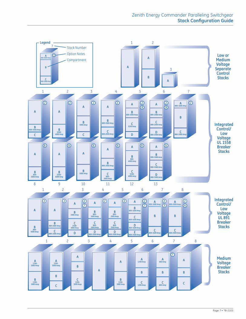
Configuration Instructions1. After designing a system one-line, you are
now ready to layout your electrical room using the enclosed switchgear and controlstacks configurator.
2. Based on system electrical requirements, choose the appropriate low voltage or medium voltage available configurations from the stack configuration guide.
3. In an effort to minimize footprint, select thenearest available Stack Number that meetsbreaker capacities. Use remaining space for fitting the appropriate controls as desired. Thecontrol and breakers definitions are included on the following pages.
4. Once the paralleling switchgear system hasbeen configured, please refer to the encloseddimension table for overall lengths, widths,depths and weights.
Zenith Energy Commander Paralleling SwitchgearStack Configuration Guide
TB-2103 • Page 6
A
B800-2000 Amp
C800-
2000 Amp
A
B3200-
4000 Amp
A
B5000 Amp
A
B800-2000 Amp
C800-2000 Amp
D800-2000 Amp
8 9 10 11 12 13
A
B800-
2000 Amp
A
B800-
4000 Amp
C3200-
4000 Amp
A
A
BA
1 2
3
A
B800-2000 Amp
C
A
C
A
B800-2000 Amp
C800-2000 Amp
A
B800-2000 Amp
A
B3200-
4000 Amp
B5000 Amp C
3200 Amp
D
A
B800-2000 Amp
C800-2000 Amp
D800-2000 Amp
A800-1600 Amp
B
C800-2000 Amp
1 2 3 4 5 6 7
1 2 3 4
A
B800-
4000 Amp
A1200-
3000 Amp
B1200-
3000 Amp
1 2 3 4
A1200-
3000 Amp
B
C
C1200-
3000 Amp
A
B
Low orMediumVoltage
SeparateControlStacks
IntegratedControl/
LowVoltageUL 1558BreakerStacks
IntegratedControl/
LowVoltageUL 891
BreakerStacks
A
B800-2000 Amp
C800-2000 Amp
A
B2000 Amp
C2500-
3000 Amp
D
A
C800-
1600 Amp
D800-2000 Amp
B800-
1600 Amp
A
C800-
2000 Amp
D800-2000 Amp
B800-
2000 Amp
A
C800-1600 Amp
D800-1600 Amp
B800-1600 Amp
E800-2000 Amp
A800-1600 Amp
B
C800-1600 Amp
A800-2000 Amp
B
C800-2000 Amp
5 6 7 8
A
A
B1200-
3000 Amp
A1200 Amp
B
C1200 Amp
A600 Amp
B
C600 Amp
A
B
C
MediumVoltageBreakerStacks
5 6 7 8
2 2 2 2 2 28
28
6 6 6 6 6 6
2 2 2 2 2 2 2 27 7 3 4
7
Legend
A800-1600 Amp
B
C800-2000 Amp
7
2
Stack Number
Option Notes
Compartment
Zenith Energy Commander Paralleling SwitchgearStack Configuration Guide
Page 7 • TB-2103
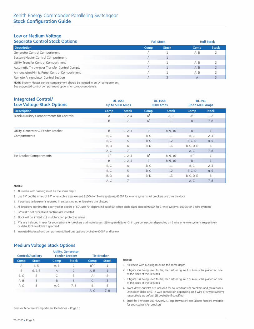
UL 1558 UL 1558 UL 891Up to 5000 Amps 6000 Amps Up to 6000 Amps
Description Comp Stack Comp Stack Comp StackBlank Auxiliary Compartments for Controls A 1, 2, 4 A3 8, 9 A3 1, 2
B 7 A4 11 B 7, 8
Utility, Generator & Feeder Breaker B 1, 2, 3 B 8, 9, 10 B 1
Compartments B, C 4 B, C 11 B, C 2, 3
B, C 5 B, C 12 B, C, D 4, 5
B, D 6 B, D 13 B, C, D, E 6
A, C 7 A, C 7, 8
Tie Breaker Compartments B5 1, 2, 3 B3 8, 9, 10 B3 1
B 1, 2, 3 B 8, 9, 10 B 1
B, C 4 B, C 11 B, C 2, 3
B, C 5 B, C 12 B, C, D 4, 5
B, D 6 B, D 13 B, C, D, E 6
A, C 7 A, C 7, 8
NOTES:
1. All stacks with bussing must be the same depth
2. Use 74" depths in lieu of 67" when cable sizes exceed 9100A for 3-wire systems, 6000A for 4-wire systems. All breakers are thru the door.
3. If bus-bus tie breaker is required in a stack, no other breakers are allowed
4. All breakers are thru the door type at depths of 60", use 70" depths in lieu of 60" when cable sizes exceed 9100A for 3-wire systems, 6000A for 4-wire systems
5. 22" width not available if controls are inserted
6. Stack will be limited to 2 multifunction protective relays
7. PT's are included in rear for source/transfer breakers and main buses: (2) in open delta or (3) in wye connection depending on 3 wire or 4 wire systems respectively as default (3) available if specified
8. Insulated/Isolated and compartmentalized bus options available 4000A and below
Medium Voltage Stack OptionsUtility, Generator,
Control/Auxiliary Feeder Breaker Tie BreakerComp Stack Comp Stack Comp Stack
A 4, 5 A, B 1 B2,3 1
B 6, 7, 8 A 2 A, B 1
B, C 2 C 3 A 2
A, B 3 B 5 C 3
A, C 8 A, C 7, 8 B 5
A, C 7, 8
Full Stack Half Stack
Description Comp Stack Comp StackGenerator Control Compartment A 1 A, B 2
System/Master Control Compartment A 1
Utility Transfer Control Compartment A 1 A, B 2
Automatic Throw-over Transfer Control Compt. A 1 A, B 2
Annunciator/Mimic Panel Control Compartment A 1 A, B 2
Remote Annunciator Control Section A 3 A 3
NOTE: System Master control compartment should be located in an “A” compartmentSee suggested control compartment options for component details.
NOTES:
1. All stacks with bussing must be the same depth
2. If figure 2 is being used for tie, then either figure 3 or 4 must be placed on oneof the sides of the tie stack
3. If figure 3 is being used for tie, then either figure 2 or 4 must be placed on oneof the sides of the tie stack
4. Front-draw-out PT's are included for source/transfer breakers and main buses:(2) in open delta or (3) in wye connection depending on 3 wire or 4 wire systemsrespectively as default (3) available if specified
5. Stack for 5KV class 100MVA only. (1) top drawout PT and (1) rear fixed PT availablefor source/transfer breakers
Breaker & Control Compartment Definitions – Page 15
TB-2103 • Page 8
Zenith Energy Commander Paralleling SwitchgearStack Configuration Guide
Low or Medium Voltage Separate Control Stack Options
Integrated Control/Low Voltage Stack Options
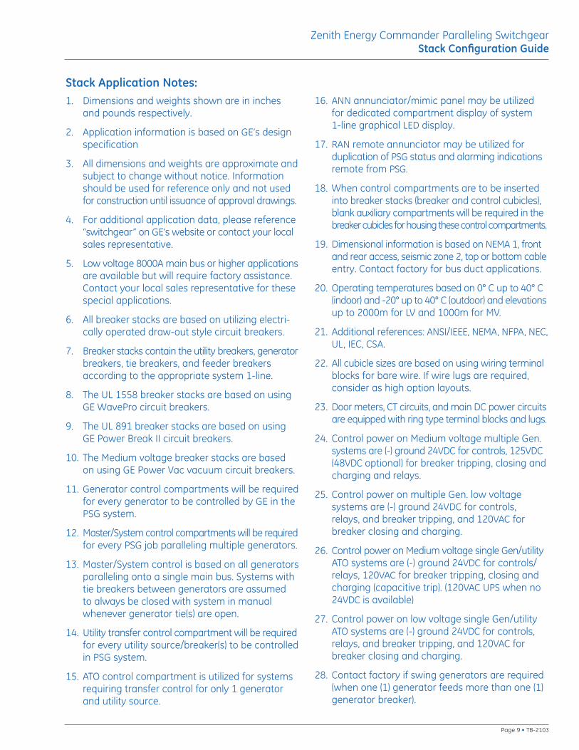
Stack Application Notes:1. Dimensions and weights shown are in inches
and pounds respectively.
2. Application information is based on GE’s designspecification
3. All dimensions and weights are approximate andsubject to change without notice. Informationshould be used for reference only and not usedfor construction until issuance of approval drawings.
4. For additional application data, please reference“switchgear” on GE’s website or contact your localsales representative.
5. Low voltage 8000A main bus or higher applicationsare available but will require factory assistance.Contact your local sales representative for thesespecial applications.
6. All breaker stacks are based on utilizing electri-cally operated draw-out style circuit breakers.
7. Breaker stacks contain the utility breakers, generatorbreakers, tie breakers, and feeder breakersaccording to the appropriate system 1-line.
8. The UL 1558 breaker stacks are based on usingGE WavePro circuit breakers.
9. The UL 891 breaker stacks are based on using GE Power Break II circuit breakers.
10. The Medium voltage breaker stacks are basedon using GE Power Vac vacuum circuit breakers.
11. Generator control compartments will be requiredfor every generator to be controlled by GE in thePSG system.
12. Master/System control compartments will be requiredfor every PSG job paralleling multiple generators.
13. Master/System control is based on all generatorsparalleling onto a single main bus. Systems withtie breakers between generators are assumedto always be closed with system in manualwhenever generator tie(s) are open.
14. Utility transfer control compartment will be requiredfor every utility source/breaker(s) to be controlledin PSG system.
15. ATO control compartment is utilized for systemsrequiring transfer control for only 1 generatorand utility source.
16. ANN annunciator/mimic panel may be utilizedfor dedicated compartment display of system 1-line graphical LED display.
17. RAN remote annunciator may be utilized forduplication of PSG status and alarming indicationsremote from PSG.
18. When control compartments are to be insertedinto breaker stacks (breaker and control cubicles),blank auxiliary compartments will be required in thebreaker cubicles for housing these control compartments.
19. Dimensional information is based on NEMA 1, frontand rear access, seismic zone 2, top or bottom cableentry. Contact factory for bus duct applications.
20. Operating temperatures based on 0° C up to 40° C(indoor) and -20° up to 40° C (outdoor) and elevationsup to 2000m for LV and 1000m for MV.
21. Additional references: ANSI/IEEE, NEMA, NFPA, NEC,UL, IEC, CSA.
22. All cubicle sizes are based on using wiring terminalblocks for bare wire. If wire lugs are required,consider as high option layouts.
23. Door meters, CT circuits, and main DC power circuitsare equipped with ring type terminal blocks and lugs.
24. Control power on Medium voltage multiple Gen.systems are (-) ground 24VDC for controls, 125VDC(48VDC optional) for breaker tripping, closing andcharging and relays.
25. Control power on multiple Gen. low voltage systems are (-) ground 24VDC for controls, relays, and breaker tripping, and 120VAC forbreaker closing and charging.
26. Control power on Medium voltage single Gen/utility ATO systems are (-) ground 24VDC for controls/relays, 120VAC for breaker tripping, closing andcharging (capacitive trip). (120VAC UPS when no24VDC is available)
27. Control power on low voltage single Gen/utilityATO systems are (-) ground 24VDC for controls,relays, and breaker tripping, and 120VAC forbreaker closing and charging.
28. Contact factory if swing generators are required(when one (1) generator feeds more than one (1)generator breaker).
Page 9 • TB-2103
Zenith Energy Commander Paralleling SwitchgearStack Configuration Guide
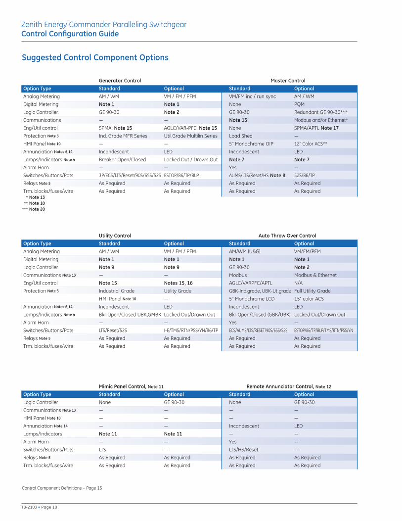
Generator Control Master ControlOption Type Standard Optional Standard OptionalAnalog Metering AM / WM VM / FM / PFM VM/FM inc / run sync AM / WM
Digital Metering Note 1 Note 1 None PQM
Logic Controller GE 90-30 Note 2 GE 90-30 Redundant GE 90-30***
Communications — — Note 13 Modbus and/or Ethernet*
Eng/Util control SPMA, Note 15 AGLC/VAR-PFC, Note 15 None SPMA/APTL Note 17Protection Note 3 Ind. Grade MFR Series Util.Grade Multilin Series Load Shed —
HMI Panel Note 10 — — 5" Monochrome OIP 12" Color ACS**
Annunciation Notes 6,14 Incandescent LED Incandescent LED
Lamps/Indicators Note 4 Breaker Open/Closed Locked Out / Drawn Out Note 7 Note 7Alarm Horn — — Yes —
Switches/Buttons/Pots 3P/ECS/LTS/Reset/90S/65S/52S ESTOP/86/TP/BLP AUMS/LTS/Reset/HS Note 8 52S/86/TP
Relays Note 5 As Required As Required As Required As Required
Trm. blocks/fuses/wire As Required As Required As Required As Required*** Note 13 *** Note 10*** Note 20
Utility Control Auto Throw Over ControlOption Type Standard Optional Standard OptionalAnalog Metering AM / WM VM / FM / PFM AM/WM (U&G) VM/FM/PFM
Digital Metering Note 1 Note 1 Note 1 Note 1Logic Controller Note 9 Note 9 GE 90-30 Note 2Communications Note 13 — — Modbus Modbus & Ethernet
Eng/Util control Note 15 Notes 15, 16 AGLC/VARPFC/APTL N/A
Protection Note 3 Industrial Grade Utility Grade GBK-Ind.grade, UBK-Ut.grade Full Utility Grade
HMI Panel Note 10 — 5" Monochrome LCD 15" color ACS
Annunciation Notes 6,14 Incandescent LED Incandescent LED
Lamps/Indicators Note 4 Bkr Open/Closed UBK,GMBK Locked Out/Drawn Out Bkr Open/Closed (GBK/UBK) Locked Out/Drawn Out
Alarm Horn — — Yes —
Switches/Buttons/Pots LTS/Reset/52S I-E/TMS/RTN/PSS/YN/86/TP ECS/AUMS/LTS/RESET/90S/65S/52S ESTOP/86/TP/BLP/TMS/RTN/PSS/YN
Relays Note 5 As Required As Required As Required As Required
Trm. blocks/fuses/wire As Required As Required As Required As Required
Mimic Panel Control, Note 11 Remote Annunciator Control, Note 12
Option Type Standard Optional Standard OptionalLogic Controller None GE 90-30 None GE 90-30
Communications Note 13 — — — —
HMI Panel Note 10 — — — —
Annunciation Note 14 — — Incandescent LED
Lamps/Indicators Note 11 Note 11 — —
Alarm Horn — — Yes —
Switches/Buttons/Pots LTS — LTS/HS/Reset —
Relays Note 5 As Required As Required As Required As Required
Trm. blocks/fuses/wire As Required As Required As Required As Required
Control Component Definitions – Page 15
TB-2103 • Page 10
Zenith Energy Commander Paralleling SwitchgearControl Configuration Guide
Suggested Control Component Options
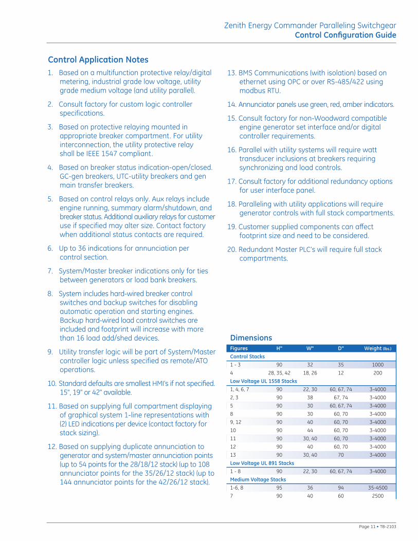
Control Application Notes1. Based on a multifunction protective relay/digital
metering, industrial grade low voltage, utilitygrade medium voltage (and utility parallel).
2. Consult factory for custom logic controller specifications.
3. Based on protective relaying mounted in appropriate breaker compartment. For utilityinterconnection, the utility protective relay shall be IEEE 1547 compliant.
4. Based on breaker status indication-open/closed.GC-gen breakers, UTC-utility breakers and genmain transfer breakers.
5. Based on control relays only. Aux relays includeengine running, summary alarm/shutdown, andbreaker status. Additional auxiliary relays for customeruse if specified may alter size. Contact factorywhen additional status contacts are required.
6. Up to 36 indications for annunciation per control section.
7. System/Master breaker indications only for tiesbetween generators or load bank breakers.
8. System includes hard-wired breaker controlswitches and backup switches for disablingautomatic operation and starting engines.Backup hard-wired load control switches areincluded and footprint will increase with morethan 16 load add/shed devices.
9. Utility transfer logic will be part of System/Mastercontroller logic unless specified as remote/ATOoperations.
10. Standard defaults are smallest HMI’s if not specified.15", 19" or 42" available.
11. Based on supplying full compartment displayingof graphical system 1-line representations with(2) LED indications per device (contact factory forstack sizing).
12. Based on supplying duplicate annunciation togenerator and system/master annunciation points(up to 54 points for the 28/18/12 stack) (up to 108annunciator points for the 35/26/12 stack) (up to144 annunciator points for the 42/26/12 stack).
13. BMS Communications (with isolation) based onethernet using OPC or over RS-485/422 usingmodbus RTU.
14. Annunciator panels use green, red, amber indicators.
15. Consult factory for non-Woodward compatibleengine generator set interface and/or digitalcontroller requirements.
16. Parallel with utility systems will require watttransducer inclusions at breakers requiring synchronizing and load controls.
17. Consult factory for additional redundancy optionsfor user interface panel.
18. Paralleling with utility applications will requiregenerator controls with full stack compartments.
19. Customer supplied components can affect footprint size and need to be considered.
20. Redundant Master PLC’s will require full stackcompartments.
DimensionsFigures H" W" D" Weight (lbs.)
Control Stacks1 - 3 90 32 35 1000
4 28, 35, 42 18, 26 12 200
Low Voltage UL 1558 Stacks1, 4, 6, 7 90 22, 30 60, 67, 74 3-4000
2, 3 90 38 67, 74 3-4000
5 90 30 60, 67, 74 3-4000
8 90 30 60, 70 3-4000
9, 12 90 40 60, 70 3-4000
10 90 44 60, 70 3-4000
11 90 30, 40 60, 70 3-4000
12 90 40 60, 70 3-4000
13 90 30, 40 70 3-4000
Low Voltage UL 891 Stacks1 - 8 90 22, 30 60, 67, 74 3-4000
Medium Voltage Stacks1-6, 8 95 36 94 35-4500
7 90 40 60 2500
Page 11 • TB-2103
Zenith Energy Commander Paralleling SwitchgearControl Configuration Guide
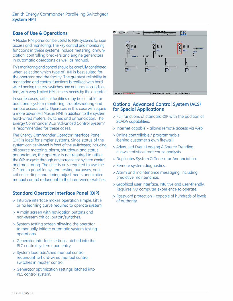
Ease of Use & OperationsA Master HMI panel can be useful to PSG systems for useraccess and monitoring. The key control and monitoringfunctions in these systems include metering, annun-ciation, controlling breakers and engine generatorsin automatic operations as well as manual.
This monitoring and control should be carefully consideredwhen selecting which type of HMI is best suited forthe operator and the facility. The greatest reliability inmonitoring and control functions is realized with hard-wired analog meters, switches and annunciation indica-tors, with very limited HMI access needs by the operator.
In some cases, critical facilities may be suitable foradditional system monitoring, troubleshooting andremote access ability. Operators in this case will requirea more advanced Master HMI in addition to the systemhard-wired meters, switches and annunciation. TheEnergy Commander ACS “Advanced Control System”is recommended for these cases.
The Energy Commander Operator Interface Panel(OIP) is ideal for simpler systems. Since status of thesystem can be viewed in front of the switchgear, includingall source metering, alarm, shutdown and statusannunciation, the operator is not required to utilizethe OIP to cycle through any screens for system controland monitoring. The user is only required to use theOIP touch panel for system testing purposes, non-critical settings and timing adjustments and limitedmanual control redundant to the hard-wired switches.
Standard Operator Interface Panel (OIP)> Intuitive interface makes operation simple. Little
or no learning curve required to operate system.
> A main screen with navigation buttons and non-system critical button/switches.
> System testing screen allowing the operator to manually initiate automatic system testingoperations.
> Generator interface settings latched into thePLC control system upon entry.
> System load add/shed manual control redundant to hard-wired manual control switches in master control.
> Generator optimization settings latched into PLC control system.
Optional Advanced Control System (ACS) for Special Applications> Full functions of standard OIP with the addition of
SCADA capabilities.
> Internet capable – allows remote access via web.
> Online controllable / programmable (behind customer’s own firewall).
> Advanced Event Logging & Source Trending allows statistical root cause analysis.
> Duplicates System & Generator Annunciation.
> Remote system diagnostics.
> Alarm and maintenance messaging, including predictive maintenance.
> Graphical user interface. Intuitive and user-friendly.Requires NO computer experience to operate.
> Password protection – capable of hundreds of levelsof authority.
Zenith Energy Commander Paralleling SwitchgearSystem HMI
TB-2103 • Page 12
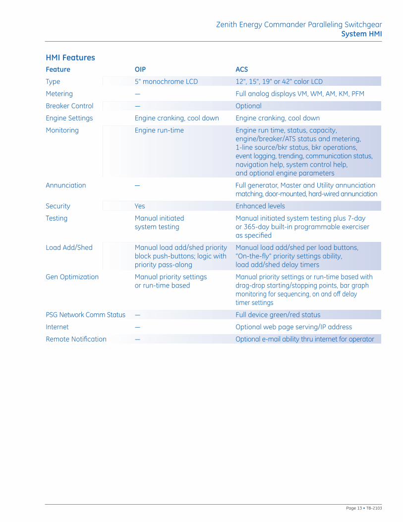
HMI FeaturesFeature OIP ACS
Type 5" monochrome LCD 12", 15", 19" or 42" color LCD
Metering — Full analog displays VM, WM, AM, KM, PFM
Breaker Control — Optional
Engine Settings Engine cranking, cool down Engine cranking, cool down
Monitoring Engine run-time Engine run time, status, capacity, engine/breaker/ATS status and metering, 1-line source/bkr status, bkr operations, event logging, trending, communication status, navigation help, system control help, and optional engine parameters
Annunciation — Full generator, Master and Utility annunciationmatching, door-mounted, hard-wired annunciation
Security Yes Enhanced levels
Testing Manual initiated Manual initiated system testing plus 7-daysystem testing or 365-day built-in programmable exerciser
as specified
Load Add/Shed Manual load add/shed priority Manual load add/shed per load buttons,block push-buttons; logic with “On-the-fly” priority settings ability, priority pass-along load add/shed delay timers
Gen Optimization Manual priority settings Manual priority settings or run-time based with or run-time based drag-drop starting/stopping points, bar graph
monitoring for sequencing, on and off delay timer settings
PSG Network Comm Status — Full device green/red status
Internet — Optional web page serving/IP address
Remote Notification — Optional e-mail ability thru internet for operator
Zenith Energy Commander Paralleling SwitchgearSystem HMI
Page 13 • TB-2103
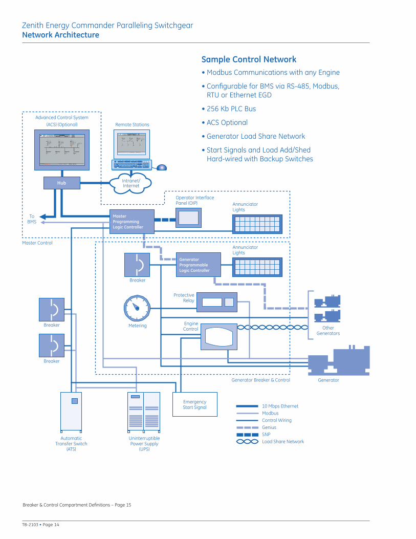
Advanced Control System
(ACS) (Optional)
Hub
MasterProgrammingLogic Controller
Breaker
Breaker
Breaker
AutomaticTransfer Switch
(ATS)
UninterruptiblePower Supply
(UPS)
EmergencyStart Signal
GeneratorGenerator Breaker & Control
Operator Interface Panel (OIP)
ProtectiveRelay
EngineControl Other
Generators
Remote Stations
Intranet/Internet
10 Mbps Ethernet
Modbus
Control Wiring
Genius
SNP
Load Share Network
Metering
Master Control
ToBMS
AnnunciatorLights
GeneratorProgrammableLogic Controller
AnnunciatorLights
Sample Control Network• Modbus Communications with any Engine
• Configurable for BMS via RS-485, Modbus, RTU or Ethernet EGD
• 256 Kb PLC Bus
• ACS Optional
• Generator Load Share Network
• Start Signals and Load Add/Shed Hard-wired with Backup Switches
Breaker & Control Compartment Definitions – Page 15
Zenith Energy Commander Paralleling SwitchgearNetwork Architecture
TB-2103 • Page 14
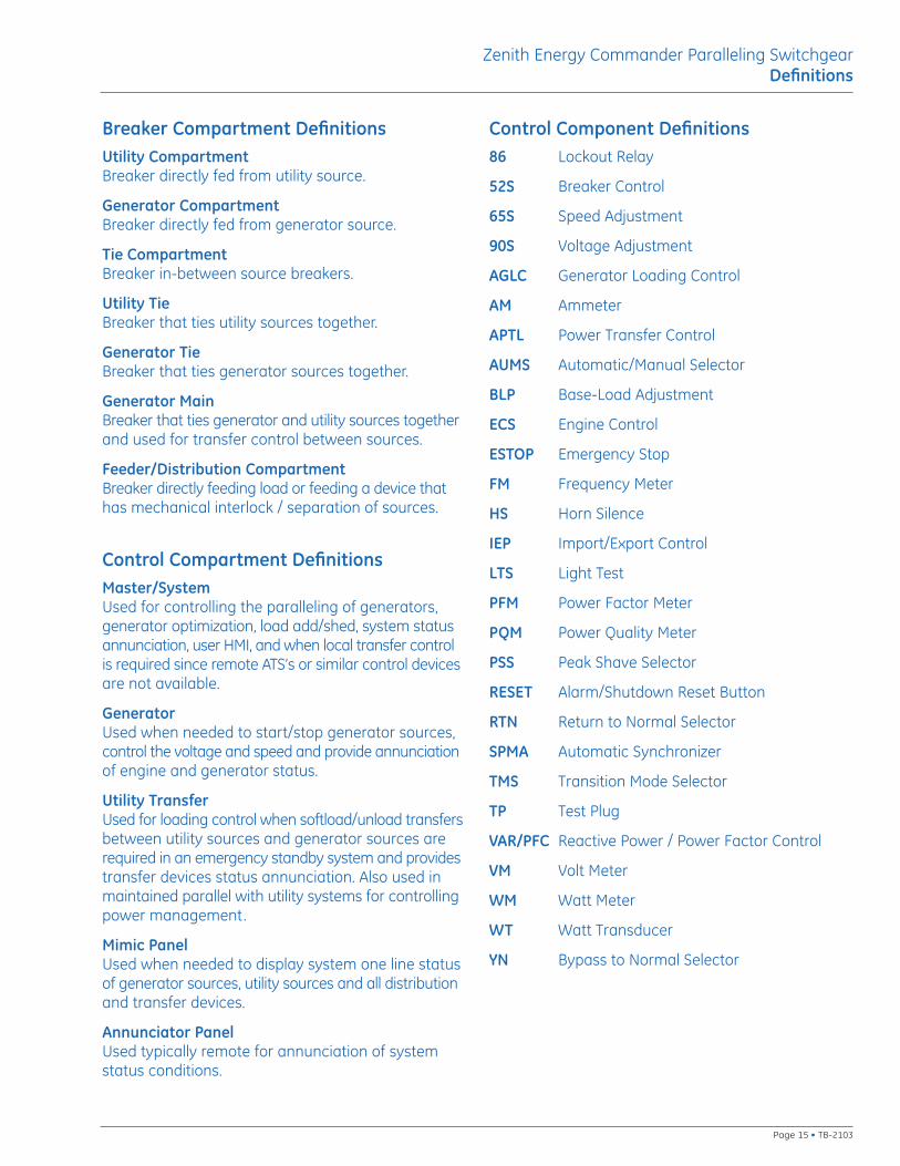
Breaker Compartment DefinitionsUtility CompartmentBreaker directly fed from utility source.
Generator CompartmentBreaker directly fed from generator source.
Tie CompartmentBreaker in-between source breakers.
Utility TieBreaker that ties utility sources together.
Generator TieBreaker that ties generator sources together.
Generator MainBreaker that ties generator and utility sources togetherand used for transfer control between sources.
Feeder/Distribution CompartmentBreaker directly feeding load or feeding a device thathas mechanical interlock / separation of sources.
Control Compartment DefinitionsMaster/SystemUsed for controlling the paralleling of generators,generator optimization, load add/shed, system statusannunciation, user HMI, and when local transfer controlis required since remote ATS’s or similar control devicesare not available.
GeneratorUsed when needed to start/stop generator sources,control the voltage and speed and provide annunciationof engine and generator status.
Utility TransferUsed for loading control when softload/unload transfersbetween utility sources and generator sources arerequired in an emergency standby system and providestransfer devices status annunciation. Also used inmaintained parallel with utility systems for controllingpower management.
Mimic PanelUsed when needed to display system one line statusof generator sources, utility sources and all distributionand transfer devices.
Annunciator PanelUsed typically remote for annunciation of systemstatus conditions.
Control Component Definitions86 Lockout Relay
52S Breaker Control
65S Speed Adjustment
90S Voltage Adjustment
AGLC Generator Loading Control
AM Ammeter
APTL Power Transfer Control
AUMS Automatic/Manual Selector
BLP Base-Load Adjustment
ECS Engine Control
ESTOP Emergency Stop
FM Frequency Meter
HS Horn Silence
IEP Import/Export Control
LTS Light Test
PFM Power Factor Meter
PQM Power Quality Meter
PSS Peak Shave Selector
RESET Alarm/Shutdown Reset Button
RTN Return to Normal Selector
SPMA Automatic Synchronizer
TMS Transition Mode Selector
TP Test Plug
VAR/PFC Reactive Power / Power Factor Control
VM Volt Meter
WM Watt Meter
WT Watt Transducer
YN Bypass to Normal Selector
Zenith Energy Commander Paralleling SwitchgearDefinitions
Page 15 • TB-2103
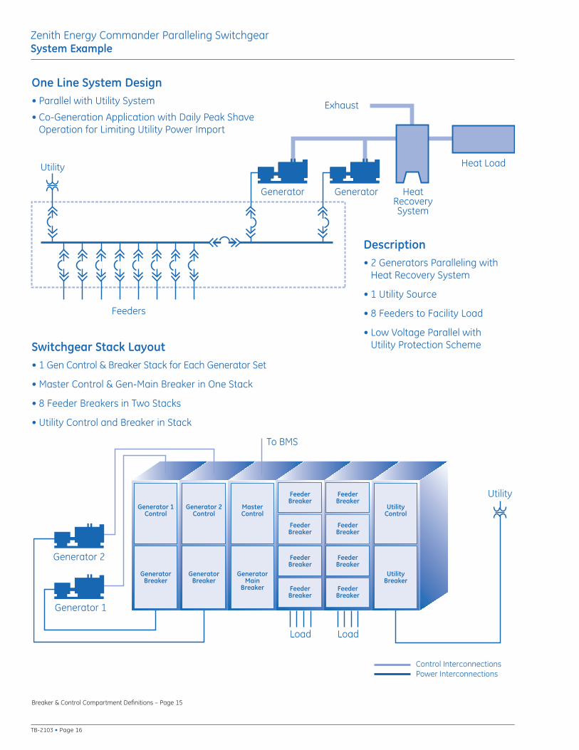
Utility
Generator Generator
Feeders
HeatRecoverySystem
Heat Load
Exhaust
Utility
Load
Generator 2
Generator 1
Control InterconnectionsPower Interconnections
Load
To BMS
Generator 1Control
GeneratorBreaker
FeederBreaker
FeederBreaker
Generator 2Control
GeneratorBreaker
MasterControl
GeneratorMain
Breaker FeederBreaker
FeederBreaker
FeederBreaker
FeederBreaker
FeederBreaker
FeederBreaker
UtilityControl
UtilityBreaker
One Line System Design• Parallel with Utility System
• Co-Generation Application with Daily Peak ShaveOperation for Limiting Utility Power Import
Description• 2 Generators Paralleling with
Heat Recovery System
• 1 Utility Source
• 8 Feeders to Facility Load
• Low Voltage Parallel with Utility Protection SchemeSwitchgear Stack Layout
• 1 Gen Control & Breaker Stack for Each Generator Set
• Master Control & Gen-Main Breaker in One Stack
• 8 Feeder Breakers in Two Stacks
• Utility Control and Breaker in Stack
Breaker & Control Compartment Definitions – Page 15
Zenith Energy Commander Paralleling SwitchgearSystem Example
TB-2103 • Page 16
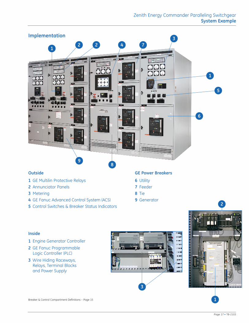
Implementation
Outside
1 GE Multilin Protective Relays
2 Annunciator Panels
3 Metering
4 GE Fanuc Advanced Control System (ACS)
5 Control Switches & Breaker Status Indicators
GE Power Breakers
6 Utility
7 Feeder
8 Tie
9 Generator
Breaker & Control Compartment Definitions – Page 15
Inside
1 Engine Generator Controller
2 GE Fanuc Programmable Logic Controller (PLC)
3 Wire Hiding Raceways, Relays, Terminal Blocks and Power Supply
Zenith Energy Commander Paralleling SwitchgearSystem Example
Page 17 • TB-2103
12 2 4 7
3
1
5
6
89
2
1
3

TB-2103 (10/10)
GE Energy – Digital Energy830 W 40th Street, Chicago, IL 60609 USA800 637 1738 www.gepowerquality.com
Information subject to change without notice. Please verify all details with GE. © 2010 General Electric Company All Rights Reserved
Contact UsWe protect and connect the world’s critical equipment to
ensure safe, reliable power
Assembled in the USA