Embed Size (px)
Citation preview

Power System Protection for TransmissionLines: Phase and Ground Distance Relays
GET-6651A


CONTENTS
Page Na
INTRODUCTION . . . . . . . . . . . . . . . . . . . . . . . . . . . . . . . . . . . . . . . . . . . . . . . . . . . . . . . . . . . . . . . . . . . . . . 1
FEATURES . . . . . . . . . . . . . . . . . . . . . . . . . . . . . . . . . . . . . . . . . . . . . . . . . . . . . . . . . . . . . . . . . . . . . . . . 1
SCOPE . . . . . . . . . . . . . . . . . . . . . . . . . . . . . . . . . . . . . . . . . . . . . . . . . . . . . . . . . . . . . . . . . . . . . . . . . . . . 1
PHASE RELAYSOperating Principle. ................................................................... 2Circuit Description. ................................................................. 5Application Considerations. ...........................................................10
GROUND RELAYSOperating Principlee . . . . . . . . . . . . . . . . . . . . . . . . . . . . . . . . . . . . . . . . . . . . . . . . . . . . . . . . . . . . . . . . . 11Circuit Description . . . . . . . . . . . . . . . . . . . . . . . . . . . . . . . . . . . . . . . . . . . . . . . . . . . . . . . . . . . . . . . . . . . 13Application Considerations. ........................................................... 18
RELAY SENSITIVITY.. . . . . . . . . . . . . . . . . . . . . . . . . . . . . . . . . . . . . . . . . . . . . . . . . . . . . . . . . . . . . . . . 20
OPERATING TIME CURVES . . . . . . . . . . . . . . . . . . . . . . . . . . . . . . . . . . . . . . . . . . . . . . . . . . . . . . . . . . 21
RELAY BURDEN, D-C DAN.. . . . . . . . . . . . . . . . . . . . . . . . . . . . . . . . . . . . . . . . . . . . . . . . . . . . . . . 21
RELAY SCHEMESS . . . . . . . . . . . . . . . . . . . . . . . . . . . . . . . . . . . . . . . . . . . . . . . . . . . . . . . . . . . . . . . . . . . . 23
SLY|SLYG 60180 Phase and Ground Distance Relays
SUMMARY OF FEATURES
1. SLY and SLYG relays in 60-series are measuring functions only and are designed foruse in factory-assembled static terminals,
2. SLY and SLYG relays in 80-series are mounted in drawout cases, and each relay has
its own surge suppression, internal power supply, and contact outputs.
3. Relays are zoned-packaged; i.e. each relay provides one zone of protection for allthree phases, with three separate measuring functions.
4. Phase relays use line-to-line voltage, supplemented by positive sequence voltage,for polarizing, which provides a continuous output for zero voltage phase-to-phaseand double-phase-to-ground faults.
5. Ground relays use quadrature voltage for one polarizing signal, and zero sequencevoltage and current for second polarizing signal. This improves performance and
makes application easier.
6. Both phase and ground relays provide automatic increase in reach along R-axis,with more arc-resistance accommodation for close-in faults, as source resistance(and arc resistance) increases.
SLY|SLYG 60/80 Phase and Ground Distance Relays
INTRODUCTION
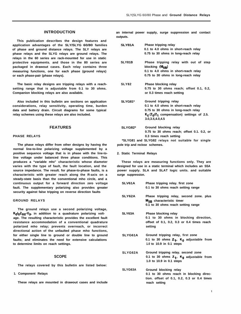
This publication describes the design features andapplication advantages of the SLY/SLYG 60/80 familiesof phase and ground distance relays. The SLY relays arephase relays and the SLYG relays are ground relays. The
relays in the 60 series are rack-mounted for use in staticprotective equipments. and those in the 80 series arepackaged in drawout cases. Each relay contains three
measuring functions, one for each phase (ground relays)or each phase-pair (phase relays).
The basic relay designs are tripping relays with a reach-setting range that is adjustable from 0.1 to 30 ohms.Companion blocking relays are also available.
Also included in this bulletin are sections on applicationconsiderations, relay sensitivity, operating time, burdendata and battery drain. Circuit diagrams for some typicalrelay schemes using these relays are also included.
FEATURES
PHASE RELAYS
The phase relays differ from other designs by having thenormal line-to-line polarizing voltage supplemented by apositive sequence voltage that is in phase with the line-to-line voltage under balanced three phase conditions. Thisproduces a “variable mho” characteristic whose diametervaries with the type of fault, the fault location, and thesource impedance. The result. for phase-to-phase faults, is acharacteristic with greater reach along the R-axis on asteady-state basis than the conventional mho circle, and acontinuous output for a forward direction zero voltagefault. The supplementary polarizing also provides greatersecurity against false tripping on reverse direction faults
GROUND RELAYS
The ground relays use a second polarizing voltage,KOIOZRO-VO, in addition to a quadrature polarizing volt-age. The resulting characteristic provides the excellent faultresistance accommodation of a conventional quadraturepolarized mho relay; prevents overreach, or incorrectdirectional action of the unfaulted phase mho functions,
for either single line to ground or double line to ground
faults; and eliminates the need for extensive calculationsto determine limits on reach settings.
SCOPE
The relays covered by this bulletin are listed below:
1. Component Relays
These relays are mounted in drawout cases and include
an internal power supply, surge suppression and contactoutputs.
SLY81A Phase tripping relay0.1 to 4.0 ohms in short-reach relay0.75 to 30 ohms in long-reach relay
SLY81B
SLY82
SLYG81*
SLYG82* Ground blocking relay0.75 to 30 ohms reach; offset 0.1. 0.2, or
0.3 times reach setting*SLYG81 and SLYG82 relays not suitable for single
pole trip and reclose schemes.
2. Static Terminal Relays
These relays are measuring functions only. They aredesigned for use in a static terminal which includes an SSApower supply. SLA and SLAT logic units. and suitablesurge suppression.
Phase tripping relay with out of step
blocking (MOB)0.1 to 4.0 ohms in short-reach relay0.75 to 30 ohms in long-reach relay
Phase blocking relay0.75 to 30 ohms reach; offset 0.1, 0.2,or 0.3 times reach setting
Ground tripping relay0.1 to 4.0 ohms in short-reach relay
0.75 to 30 ohms in long-reach relayK. (Zd2, compensation) settings of 2.5.3.0,3.5,4.0,4.5
SLV61A
SLY62A
SLY63A
SLYG61A
SLYG62A
SLYG63A
Phase tripping relay. first zone0.1 to 30 ohms reach setting range
Phase tripping relay, second zone. plus
MOB characteristic timer0.1 to 30 ohms reach setting range
Phase blocking relay0.1 to 30 ohms in blocking direction,
offset of 0.1, 0.2, 0.3 or 0.4 times reachsetting
Ground tripping relay, first zone
0.1 to 30 ohms 2,. K. adjustable from1.0 to 10.9 in 0.1 steps
Ground tripping relay. second zone0.1 to 30 ohms 2,. K. adjustable from1.0 to 10.9 in 0.1 steps
Ground blocking relay0.1 to 30 ohms reach in blocking direc-
tion. offset of 0.1, 0.2, 0.3 or 0.4 timesreach setting
SLY|SLYG 60160 phase and Ground Distance Relays
SLYG61 P* Simi lar to SLYGGIA except l ine- to-neutral polarized
SLYG62P* Simi lar to SLYG62A except line-to-
neutral polarized
SLYG63P* Simi lar to SLYG63A except l ine- to-neutral polarized
*For use in single pole trip and reclose schemes.
L IST OF SYMBOLS
SLCSLYSLYG
I4 Ig Ic ==
“0"AN- "EN, "CN =“AB.“g:,“CA=’“0“A231
=
“P=Rs2Rl
‘RO
=SRFKO
Static-Line-Current R e l a yStatic-Line-Admittance Relay
Static-Line-Admittance-GroundRelayLine CurrentsZero sequence currentLine to neutral voltagesLine to line voltages
Zero sequence voltage
ferenced to VmPolarizing voltageRelay positive sequence replicaimpedanceRelay zero sequence replica im-pedancesource inpedance
Fault resistanceAdjustable compensation factorfor ratio of zero sequence to
positive sequence inpedance
(&$Zj) of line
PHASE RELAYS
PRINCIPLE OF OPERATION, SLY61 & SLY81TRIPPING RELAYS
These relays contain single-phase mho functions thatoperate on the same basic principle as mho functions ofconventional design. such as the SLY51 relay. In this
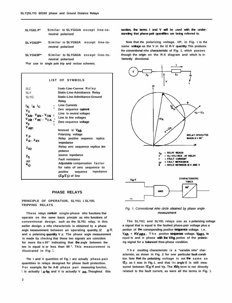
earlier design. a mho characteristic is obtained by a phaseangle measurement between an operating quantity, IZ R-V.and a polarizing quantity V p. The phase angle measurementis made by checkng that these two signals are coincidentfor more tha n 90° indicating that ti angle between thetwo is equal to or less than 90 °. This measurement isillustrated in Fig 1.
The I and V quantities of Fig. 1 are actually phase-pairquantities in relays designed for phase fault protection.For example. for !he A-B phase pair measuring function,I is actually I ~_lg and V is actually V AB Thoughout this
2
Note that the polarizing voltage. VP, in Fig. 1 is thesame voltage as the V in the I2 R-V quantity. This produces
the conventional mho characteristic of Fig. 1. which passesthough the origin on the R-X diagram and which is in-herently directional.
The SLY61 and SLY81 relays use as a polarizing voltagea signal that is equal to the faulted phase-pair voltage plus aportion of the corresponding posilive sequence voltage. i.e.Vm + KVm,. T h e positive -“ce voltage. Vm,, isequal to and in phase ti ti “As portion of the polariz-ing signal for a balanced thee-phase condition.
T h e resulting characteristic is a “variable mho” char-acteristic, as shown in Fig. 2 for one particular fault condi-tion. Note that the polarizing voltage is not the same asIZF. as it was in Fig. 1. and that t h e angle 8 is still mea-sured between IZR-V and Vp. The KV, term is not directly
related to the fault current, as were all the terms in Fig. 1.
SLY/SLYG 60/80 Phase and Ground Distance Relays
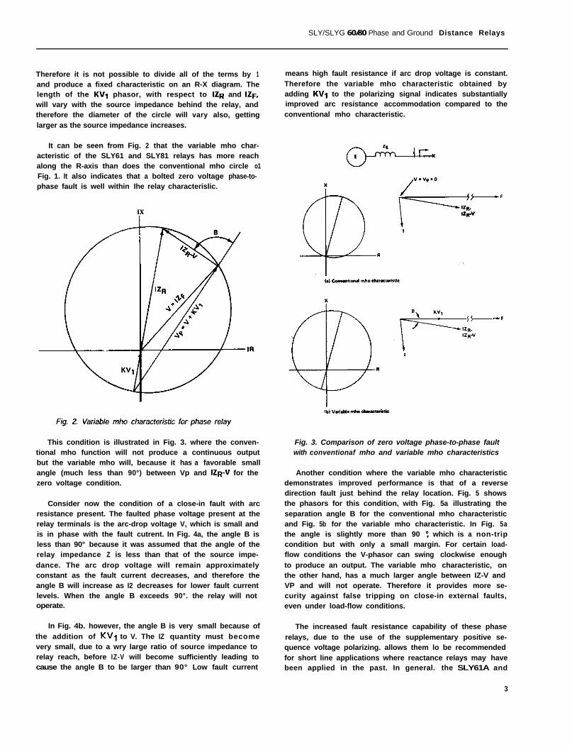
Therefore it is not possible to divide all of the terms by 1and produce a fixed characteristic on an R-X diagram. Thelength of the KV, phasor, with respect to IZR and IZF.will vary with the source impedance behind the relay, andtherefore the diameter of the circle will vary also, gettinglarger as the source impedance increases.
It can be seen from Fig. 2 that the variable mho char-acteristic of the SLY61 and SLY81 relays has more reachalong the R-axis than does the conventional mho circle o1Fig. 1. It also indicates that a bolted zero voltage phase-to-phase fault is well within Ihe relay characterislic.
means high fault resistance if arc drop voltage is constant.Therefore the variable mho characteristic obtained byadding KV1 to the polarizing signal indicates substantiallyimproved arc resistance accommodation compared to theconventional mho characteristic.
Irx
This condition is illustrated in Fig. 3. where the conven-tional mho function will not produce a continuous outputbut the variable mho will, because it has a favorable smallangle (much less than 90°) between Vp and IZR_V for thezero voltage condition.
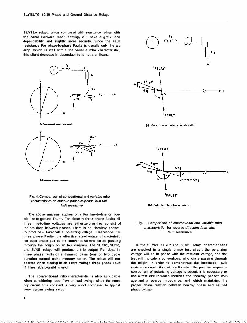
Consider now the condition of a close-in fault with arcresistance present. The faulted phase voltage present at therelay terminals is the arc-drop voltage V, which is small andis in phase with the fault cutrent. In Fig. 4a, the angle B isless than 90° because it was assumed that the angle of therelay impedance Z is less than that of the source impe-
dance. The arc drop voltage will remain approximatelyconstant as the fault current decreases, and therefore theangle B will increase as I2 decreases for lower fault currentlevels. When the angle B exceeds 90°. the relay will notoperate.
In Fig. 4b. however, the angle B is very small because of
the addition of KV, to V. The IZ quantity must becomevery small, due to a wry large ratio of source impedance torelay reach, before IZ-V will become sufficiently leading tocause the angle B to be larger than 90° Low fault current
Fig. 3. Comparison of zero voltage phase-to-phase faultwith conventionaf mho and variable mho characteristics
Another condition where the variable mho characteristicdemonstrates improved performance is that of a reversedirection fault just behind the relay location. Fig. 5 showsthe phasors for this condition, with Fig. 5a illustrating theseparation angle B for the conventional mho characteristicand Fig. 5b for the variable mho characteristic. In Fig. 5athe angle is slightly more than 90 “. which is a non-tripcondition but with only a small margin. For certain load-flow conditions the V-phasor can swing clockwise enough
to produce an output. The variable mho characteristic, onthe other hand, has a much larger angle between IZ-V andVP and will not operate. Therefore it provides more se-curity against false tripping on close-in external faults,even under load-flow conditions.
The increased fault resistance capability of these phase
relays, due to the use of the supplementary positive se-quence voltage polarizing. allows them lo be recommendedfor short line applications where reactance relays may havebeen applied in the past. In general. the SLY61A and
3
SLYISLYG 60/80 Phase and Ground Distance Relays
SLY81A relays, when compared with reactance relays withthe same Forward reach setting, will have slightly lessdependability and slightly more security. Since the Faultresistance For phase-to-phase Faults is usually only the arc
drop, which is well within the variable mho characteristic,this slight decrease in dependability is not significant.
Fig. 4. Comparison of conventional and variable mhocharacteristics on close-in phase-m-phase fault with
fault resistance
The above analysis applies only For line-to-line or dou-ble-line-to-ground Faults. For close-in three phase Faults all
three line-to-line voltages are either zero or they consist ofthe arc drop between phases. There is no “healthy phase”to produce a Favorable polarizing voltage. Therefore, fo rthree phase Faults. the effective steady-state characteristicfor each phase pair is the conventional mho circle passingthrough the origin on an R-X diagram. The SLY61, SLY62,and SLY81 relays will produce a trip output For dose-in
three phase faults on a dynamic basis (one or two cycleduration output) using memory action. The relays will notoperate when closing in on a zero voltage three phase Fault
i f l ine side potential is used.
The conventional mho characteristic is also applicablewhen considering load flow or load swings since the mem-ory circuit time constant is very short compared to typicalpow system swing rates.
Fig. 5. Comparison of conventional and variable mho
characteristic for reverse direction fault withfault resistance
IF the SLY61. SLY62 and SLY81 relay characteristicsare checked in a single phase test circuit the polarizingvoltage will be in phase with the restraint voltage, and thetest will indicate a conventional mho circle passing throughthe origin. In order to demonstrate the increased Faultresistance capability that results when the positive sequencecomponent of polarizing voltage is added, it is necessary touse a test circuit which includes the ‘healthy phase” volt-age and a source impedance, and which maintains the
proper phase relation between healthy phase and Faultedphase voltages.
SLY/SLYG 60/80 Phase and Ground Distance Relays
BLOCKING RELAYS, SLY63 AND SLY82
These two designs of blocking relays also use a polarizing
voltage that contains a supplementary positive sequencecomponent. Therefore they will produce a continuousoutput for zero voltage phase-to-phase faults even withoutthe IZ offset normally used for that purpose.
The I Z offset quantity is included in the polarizingquantity of these relays. and it serves two purposes, de-
pending on the type of fault. For a zero voltage threephase fault, it provides a fixed offset and insures a con-tinuous output even though the polarizing voltage is zero.
For phase-lo-phase faults. it helps to insure proper coordi-nation of tripping and blocking relay operating times underload flow conditions by shifting the prefault voltage in thedirection of the voltage at the opposite terminal. Thememory action in the polarizing circuit causes the relay toremember this prefault voltage for the first few cycles afterthe fault occurs.
The offset in the phase blocking relays. then, is a fixedoffset for three phase faults and a compensating quantityfor phase-to-phase faults. The optimum setting of the offsetwill vary with the length of the line and the ratio of block-ing relay reach to protected line length. A typical settingfor the offset is 30% of the reach setting in the directionaway from the protected line.
CIRCUIT DESCRIPTION FOR PHASE RELAYS
1. SLY81A or SLY81B Relay
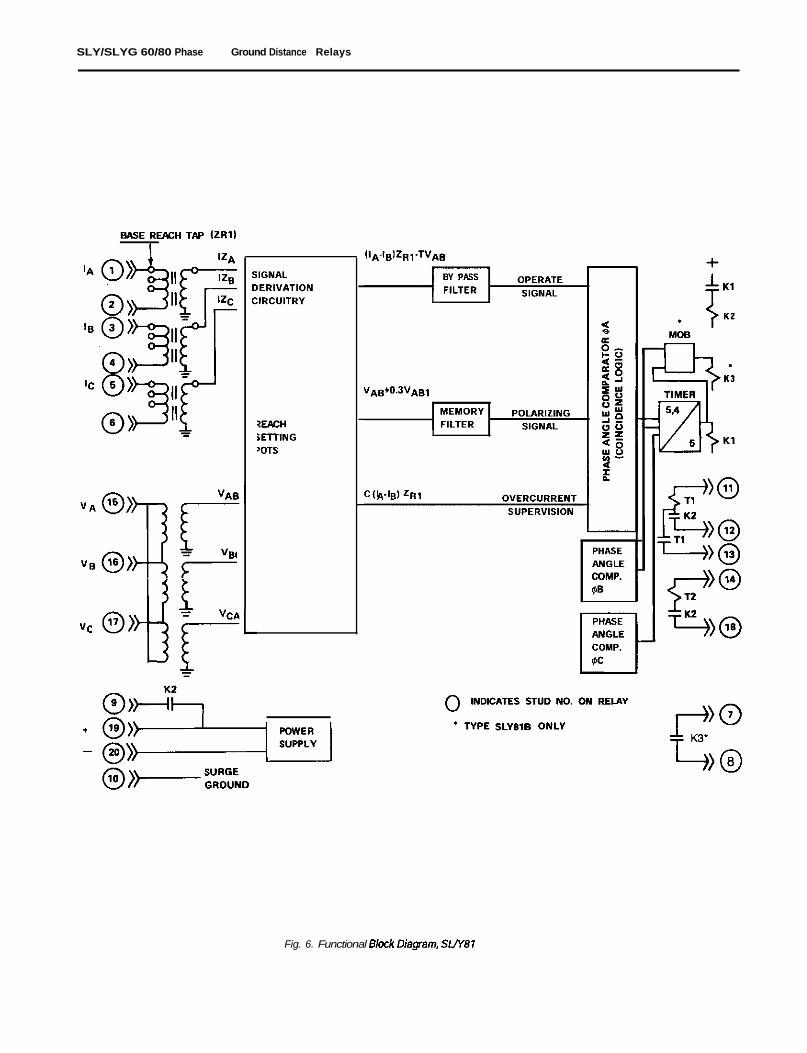
A functional block diagram of the SLY81A or SLY81Btripping relay is shown in Fig. 6. These two relays areidentical except for the fact that the SLY818 contains the
MOB function, while the SLY81A does not. This diagramshows input currents and voltages for all three phases. andcoincidence logic input signals for the AB phase pair only.These signals are:
(iA-l8)zR+VA8, where zR1 is base reach tap setting(ohms) and T is the percent restraint setting.
VAB + 0.3 VA81, where VA81 is the positive sequencenetwork output. in phase with VAT.
and c(lA-l8)Z~f, where C is an adjustable multiplier
used to determine the sensitivity setting of this input signal.
The output of the coincidence logic is supplied to thecharacteristic timer (5,4/5), and the output of the timer
operates the KI relay, which in turn operates the K2 out-put relay.
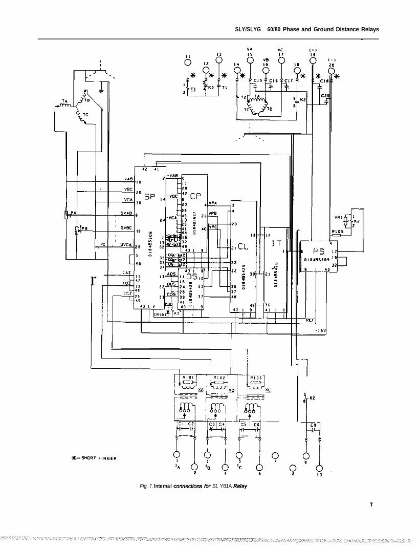
The internal connection diagram for the SLY81A orSLY818 is shown in Fig. 7. The six cards in the relay areidentified as:
SP Signal ProcessingCP Combined PolarizingOS Operate SignalCL Coincidence LogicIT Integrating TimerPS Power Supply
Base reach tap adjustments are made by moving adjust-able leads connected to studs 1, 3, and 5 to one of threepositions. These are 0.1. 0.2 and 0.4 ohms for the short-reach relay, and 0.75. 1.5 and 3.0 ohms for the long-reach
relay. The potentiometer settings marked as PA, P8. andPC are on the ganged precision potentiometer and are usedto make the restraint voltage setting.
These relays include an overcurrent supervision function
which will block operation if the fault current is not abovethe setting of this Function. This will provide protectionagainst false tripping due to blown potential fuses if it is
possible to choose a setting that is greater than maximumload current and less than minimum fault current. The ad-
justment of this Function is controlled by three potentio-meters on the SP card. The range of adjustment For thevarious base reach taps is given below:
Base Reach, Ohms R a n g e A m p e r e s
0 . 1 4-10
0.2 2-10
0.4 l - 1 00.75 0.52-10
1.5 0.23-10
3.0 0.13-10
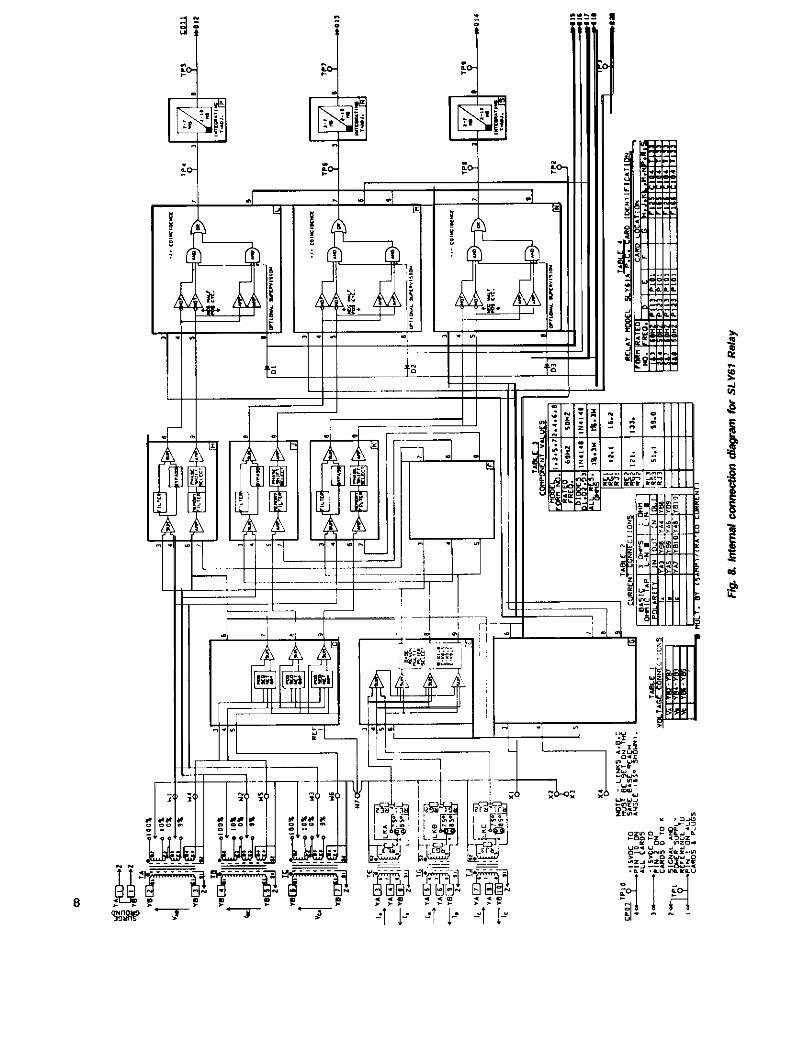
2. SLY61 Relay
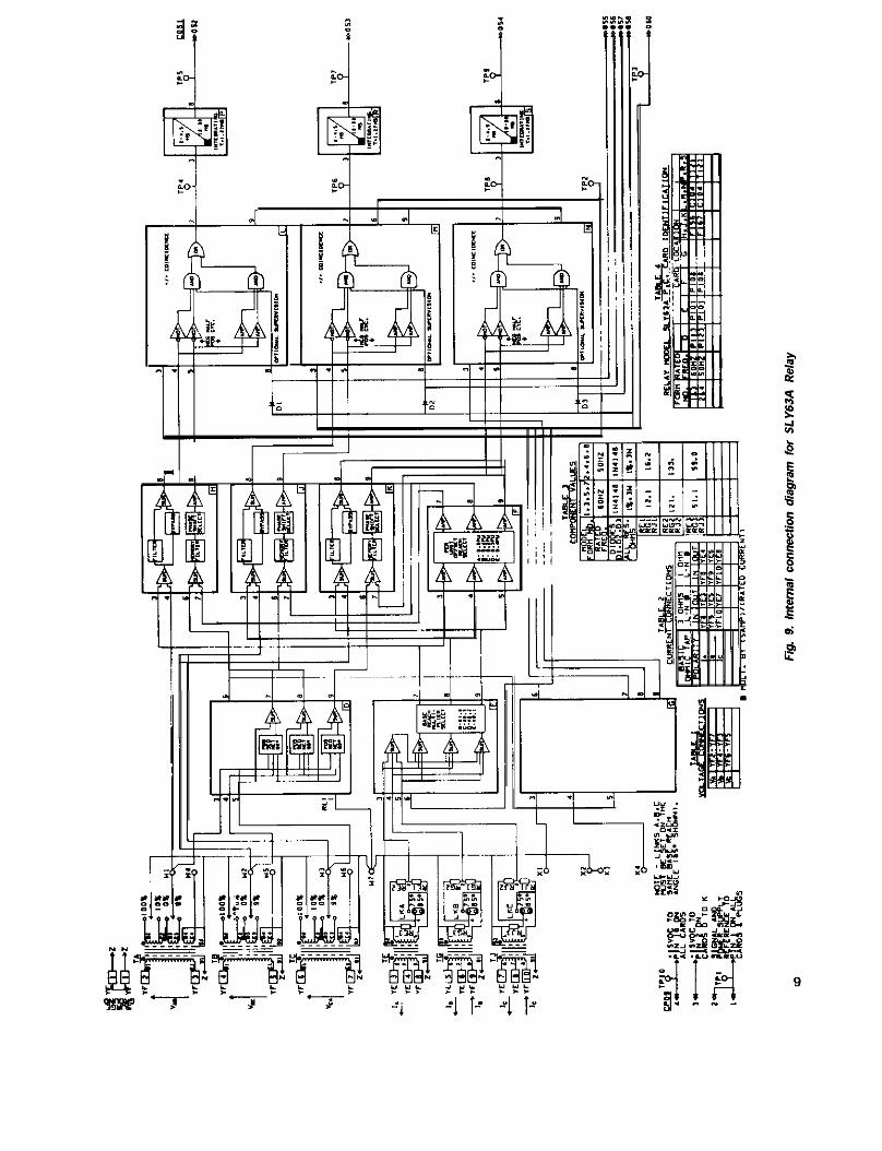
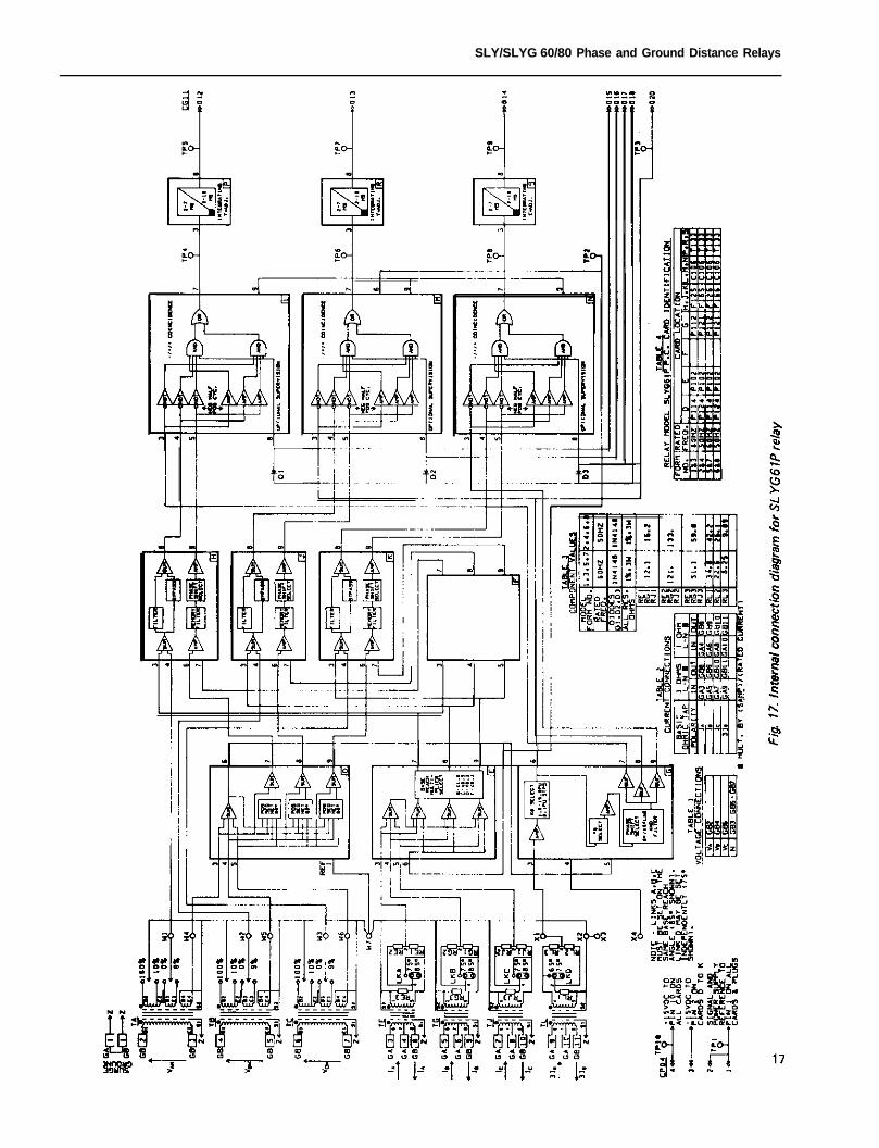
The internal connection diagram For the SLY61 trippingrelay is shown in Fig. 8. In this diagram, card positions areshown in the lower right hand corner of the card block, and
the card identification is given in Table 4.
Base reach settings are determined by the current circuitconnections to the YA block on the rear of the relay. andmay be further adjusted by the base reach multiplier (1.0,0.5. 0.2, or 0.1) on the E card. The voltage restraint is ad-justed by three separate pairs of tap blocks, and the D cardadds the positive sequence polarizing quantity.
The IZR and V restraint signals are added at pins 3 and4 on the H, J. and K cards, and the polarizing voltage sig-nals are applied to pin 6 of these three cards. The outputsignals on these cards are A-C signals (both polarities) butare essentially square waves because of Ihe high gain on theoutput amplifiers on the H. J, and K cards.
The coincidence logic cards (L, M, and N) product? an
input to the corresponding integrating timer cards (P, R, or
SLY/SLYG 60/80 Phase Ground Distance Relays
“c
+
-
! !L
Fig. 6. Functional
SLY/SLYG 60/80 Phase and Ground Distance Relays
r
Fig. 7. Internal connections for SL Y81A R&y
I, III
SLY/SLYG 60/80 Phase and Ground Distance Relays
S) when the input signals are either both positive or bothnegative. The width of the block at the coincidence logicoutput is a measure of the phase angle between I++and V.
APPLICATION CONSIDERATIONS, PHASE RELAYS
1. Reach Setting. First Zone Relays
Overcurrent supervision of the coincidence logic output(for blown fuse protection) is optional and may be eitherphase by phase (pins 015, 016, and 017) or a single signalinput at 018. When this supervising signal is held at thereference level there is no output from the coincidencelogic. When it is either a plus voltage or an open circuitcondition, the coincidence logic is not blocked fromoperating. The phase by phase supervision is typicallyused in single pole trip and reclose schemes.
The SLY81 relay has a fixed maximum reach angle of85° . The relay can be set to cover up to 90% of the lineimpedance for positive sequence impedance angles above76°. and up to 85% of the line for positive sequence im-pedance angles above 70°. For line angles lower than 70°the reach should not exceed 90% of the reactive componentof the line impedance.
The setting of the integrating timer determines theshape of the relay characteristic. A setting equal to 90”(4.16 ms. at 60Hz) produces a circular characteristic.
The SLY61 relay has a base reach angle that is adjustableby means of links on the rear of the unit, and these may beset for either 85° or 75° . In addition, the polarizing voltagemay be shifted leading by 15°. which shifts the relay char-acteristic clockwise by 15°. This provides two additionalchoices of 70° or 60° maximum reach angle. When this 15°shift is used, the reach at the maximum reach angle isincreased slightly (by 3%) over the tap value.
3. SLY62A Relay
The SLY62A relay is similar to the SLY61A except thatthe SLY62A is intended for use as an overreaching, orsecond zone mho distance relay. The SLY62A providesslightly faster speed. and has more transient overreach thanthe SLYBlA relay. The SLY62A also includes an MO6characteristic timer which can be used as part of an out-of-step detection scheme.
In the SLY61 it is recommended that the 95° angleshould be used for line angles greater than 80°. and that the75” angle should be used for angles of 80° and below. Thesuggested reach setting is 90% of the line for positive se-quence line angles of 65 ° and above. For line angles below65° the reach should not exceed 90% of the reactivecomponent of the line impedance.
The 15 ° phase shift is normally not used but can be anadvantage in special applications.
4. SLY82A Relay (Blocking)2. Reach Setting, Second Zone Relays
The SLY82A relay is similar to the SLY81A relay ex-cept that it is designed for use as a blocking relay in adirectional comparison scheme. The polarizing quantityhas an 12 quantity added to it, in addition to the supple.mentary positive sequence polarizing. Reach in the blockingdirection is adjustable from 0.75 to 30 ohms. and thepercentage of IZ (or offset) added to the polarizing signalis adjustable to provide a choice of 10%. 26% or 30%.
The choice of the second zone reach setting will beaffected by the application. For example, if the relay isused in a stepped distance scheme. its reach will have to becoordinated with first zone distance relays in adjacent lines,so as not to reach farther than those first zone relays.
The SLY82A also has a normally closed contact outputfor use in schemes where the opening of a normally closedcontact is desirable for transmitting a blocking signal.
5. SLY63A Relay (Blocking)
On the other hand. if the primary purpose of the secondzone relay is to determine direction of fault current flow ina directional comparison scheme, the reach may be set con-siderably longer than the protected line in order to obtainfaster speed for remote line-end faults and for more faultresistance capability. However. longer reach settings intro-duce the possibility of misoperation due to heavy loadtransfer. or swing conditions, and therefore the reachsetting chosen will be a compromise between better perfor-mance and more security.
The SLY63A relay is similar to the SLY61A except Another way to improve the security is to use a lensthat it is designed for use as a blocking relay in a direc- instead of a circular characteristic. This is accomplished bytional comparison scheme. The polarizing quantity has an increasing the characteristic timer setting. The MT functionIZ quantity added to it, in add&n to the supplementary uses an integrating timer. where the duration of a singlepositive sequence polarizing. Reach in the blocking direc- pulse to cause an output is greater than the duration of ation is adjustable from 0.1 to 30 ohms, and the percentage steady state pulse to cause an output. A setting of 4.2 msof IZ (or offset) added to the polarizing signal is adjustable (at 60 Hz) for the steady state pulse produces a circularto provide a choice of 10%. 20%. 30% or 40%. characteristic.
10
SLY|SLYG 60/80 Phase and Ground Distance Relays
The following values of reach setting as a percentage ofline length, and of characteristic timer settings. are typicaldirectional comparison second zone settings. These arebased on an assumption that the maximum load flow undernon-emergency conditions is not greater than twice thesurge impedance loading of the line. The characteristictimer settings are for 60 Hz applications.
Line Length ReachMiles % of Line
0 - 5 0 2005 0 1 0 0 175
100-150 150150-200 135200-300 125
Characteristic Timer (ms)First Pulse steady state
5.5 4.2
6.6 4.2
6.6 4.86.0 6.66.5 6.6
3. Overcurrent Supervision
The overcurrent supervision function in the SLY91relay should be set above maximum load current and belowminimum fault current, if possible, to provide protection
against false tripping due to loss of potential (blown fuses).
In the SLY61 relay, overcurrent supervision may beprovided at the coincidence logic in the SLY61 or at anAND function in the associated SLA relay. The latter
method is used in the example shown in Fig. 24.
4. MBB Characteristic
The SLY62 relay contains the MG8 characteristic timer,which produces a tomato-shaped characteristic with the
same forward reach as the MT characteristic. The setting ofthe Mo8 characteristic timers will normally be based onload flow and power swing studies.
The SLY818 relay contains the complete MG8 function,including the characteristic timer as well as the timer usedto indicate that the apparent impedance is inside MG8 butoutside of MT for a fixed time. An appropriate setting ofthis second timer is usually between two and four cycles.The SLY818 also has en option whereby MG8 will blocktripping with the “OSR” plug in one position and will notblock tripping for the other position. In either case. there isan OSB contact output available for use in an externalcontrol circuit.
G R O U N D R E L A Y S
PRINCIPLE OF OPERATION OF SLYG61 ANDSLYG81 RELAYS
The basic operating principle of these relays is that of a
quadrature polarized ground distance relay with a variablemho characteristic. The distance measurement is made by a
phase angle measurement between the operating voltageIIZR-VI and the polarizing voltage (VP). Additional inputs
are used to improve the security of the relay. The mostsignificant additional input is a second polarizing signal.which is a zero sequence voltage signal (Vo), supplemented
by an IoZRG component.
Both relays use a fourth input. IGZRG, but it is intro-duced in a different manner in the two relay types. In theSLYG61 relay, there is provision for introducing an SLCrelay level detector output to supervise the coincidencelogic card. In the SLYG81 relay, the IoZRo signal is usedas a fourth input to the coincidence logic card. In both
cases, this IoZRG supervision provides a degree of securityif potential is lost on one phase with load transfer over the
line.
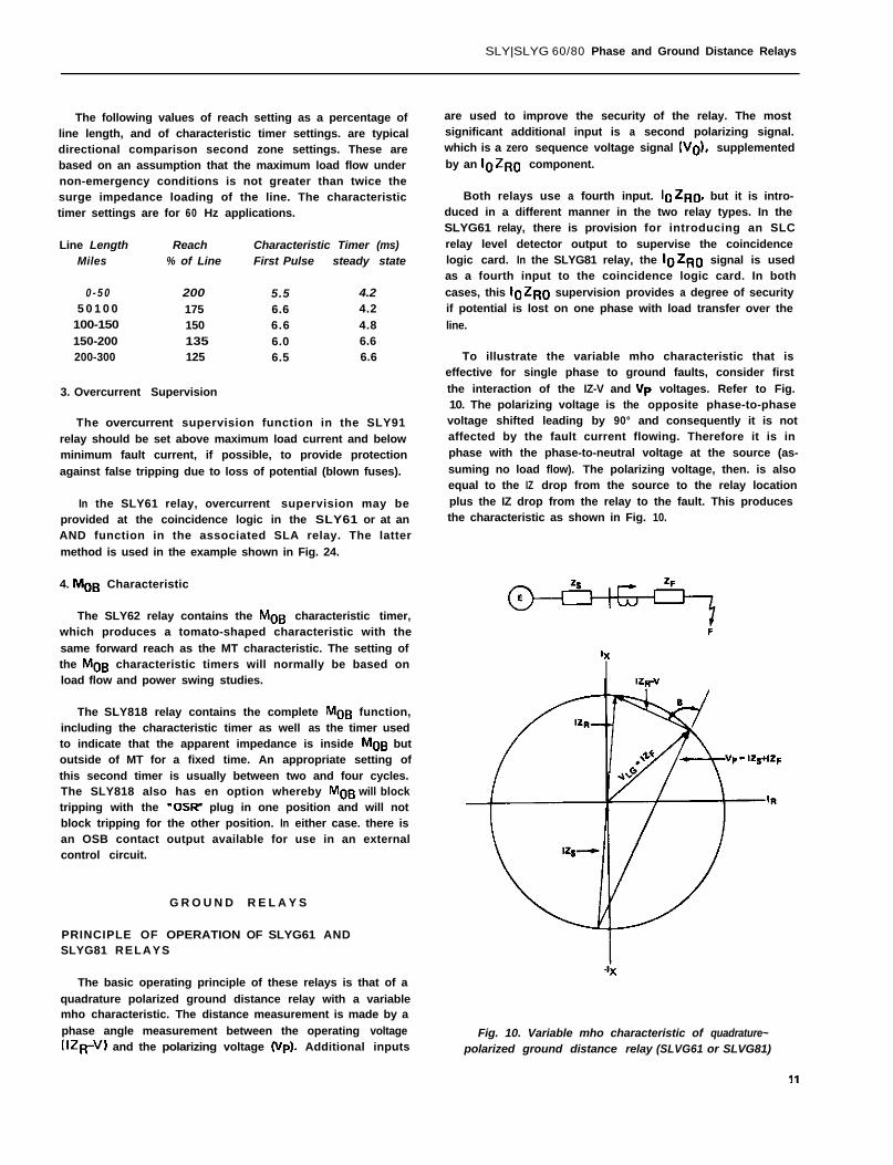
To illustrate the variable mho characteristic that iseffective for single phase to ground faults, consider first
the interaction of the IZ-V and Yp voltages. Refer to Fig.10. The polarizing voltage is the opposite phase-to-phasevoltage shifted leading by 90° and consequently it is notaffected by the fault current flowing. Therefore it is inphase with the phase-to-neutral voltage at the source (as-
suming no load flow). The polarizing voltage, then. is alsoequal to the IZ drop from the source to the relay locationplus the IZ drop from the relay to the fault. This producesthe characteristic as shown in Fig. 10.
.ix
Fig. 10. Variable mho characteristic of quadrature~polarized ground distance relay (SLVG61 or SLVG81)
SLY/SLYG 60/80 Phase and Ground Distance Relays
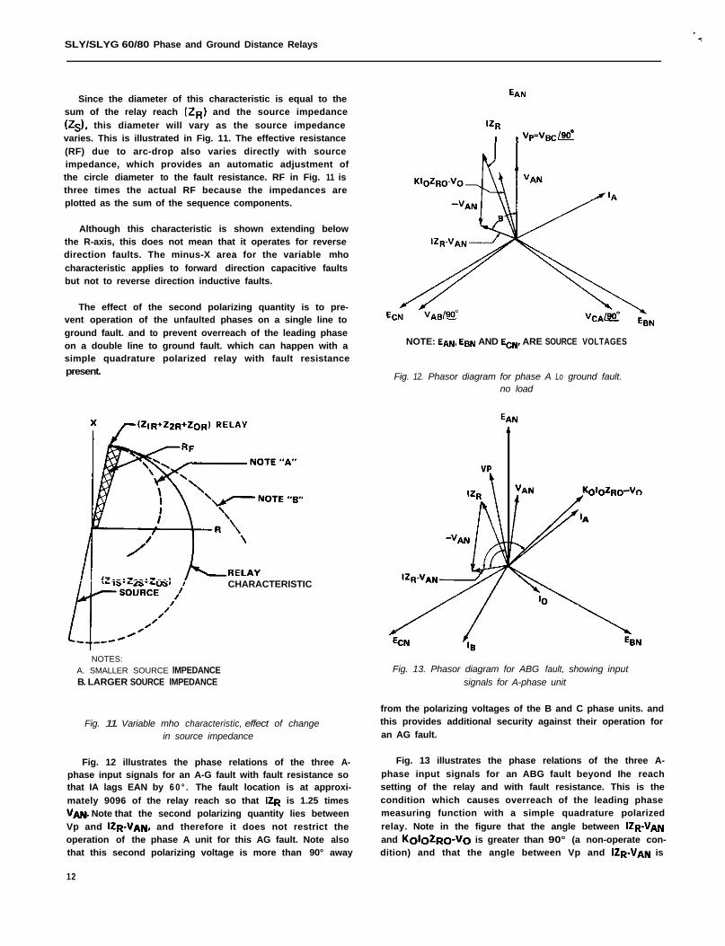
Since the diameter of this characteristic is equal to thesum of the relay reach (2~) and the source impedance
(2s). this diameter will vary as the source impedancevaries. This is illustrated in Fig. 11. The effective resistance(RF) due to arc-drop also varies directly with sourceimpedance, which provides an automatic adjustment ofthe circle diameter to the fault resistance. RF in Fig. 11 isthree times the actual RF because the impedances areplotted as the sum of the sequence components.
Although this characteristic is shown extending belowthe R-axis, this does not mean that it operates for reversedirection faults. The minus-X area for the variable mho
characteristic applies to forward direction capacitive faultsbut not to reverse direction inductive faults.
The effect of the second polarizing quantity is to pre-vent operation of the unfaulted phases on a single line toground fault. and to prevent overreach of the leading phaseon a double line to ground fault. which can happen with asimple quadrature polarized relay with fault resistancepresent.
CHARACTERISTIC
NOTES:A. SMALLER SOURCE lMPEDANCEB. LARGER SOURCE lMPEDANCE
Fig. 11. Variable mho characteristic, effect of changein source impedance
from the polarizing voltages of the B and C phase units. andthis provides additional security against their operation foran AG fault.
Fig. 12 illustrates the phase relations of the three A- Fig. 13 illustrates the phase relations of the three A-
phase input signals for an A-G fault with fault resistance so phase input signals for an ABG fault beyond Ihe reachthat IA lags EAN by 6 0 ° . The fault location is at approxi- setting of the relay and with fault resistance. This is the
mately 9096 of the relay reach so that IZR is 1.25 times condition which causes overreach of the leading phase
VAN. Note that the second polarizing quantity lies between measuring function with a simple quadrature polarized
Vp and IZR_VAN, and therefore it does not restrict the relay. Note in the figure that the angle between Q-VANoperation of the phase A unit for this AG fault. Note also and KoIoZRO-VO is greater than 90° (a non-operate con-that this second polarizing voltage is more than 90° away dition) and that the angle between Vp and Q-VAN is
12
EAN
NOTE: EAN. E9,, AND ECN, ARE SOURCE VOLTAGES
Fig. 12. Phasor diagram for phase A Lo ground fault.no load
Fig. 13. Phasor diagram for ABG fault, showing inputsignals for A-phase unit
SLY/SLYG 60180 Phase and Ground Distance Relays
less than 9 0 ° (an operate condition). This illustrates howthe second polarizing signal (KGIGZRG-VG) prevents over-reach for this fault condition.
Because of the large reach along the R-axis that resultsfrom the variable mho characteristic. these relays arerecommended for short line applications where reactancerelays may have been applied in the past. In addition. theserelays provide greater security against overreaching for con-ditions of high resistance ground faults in combination withheavy load flow. This condition can cause the apparentimpedance seen by a reactance relay to fall within itscharacteristic for a fault beyond the reach setting of therelay. For a more detailed description of this condition. seeIEEE paper F78 743-7. “Design Considerations in theDevelopment of a New Ground Distance Relay," by Wilkin-son. Mathews and Keeney (GER 3089).
If the SLYG61 and SLYG81 relay characteristics arechecked in a test circuit where all three voltages are phase-shifted together, the result will be a mho circle that passesthrough the origin. In order to demonstrate the increasedfault resistance capability of these relays, they must bechecked in a test circuit which includes the effect of sourceimpedance and which produces the proper phase relationbetween polarizing and restraint voltages.
CIRCUIT DESCRlPTlON FOR GROUND RELAYS
1. SLYG81 Relay
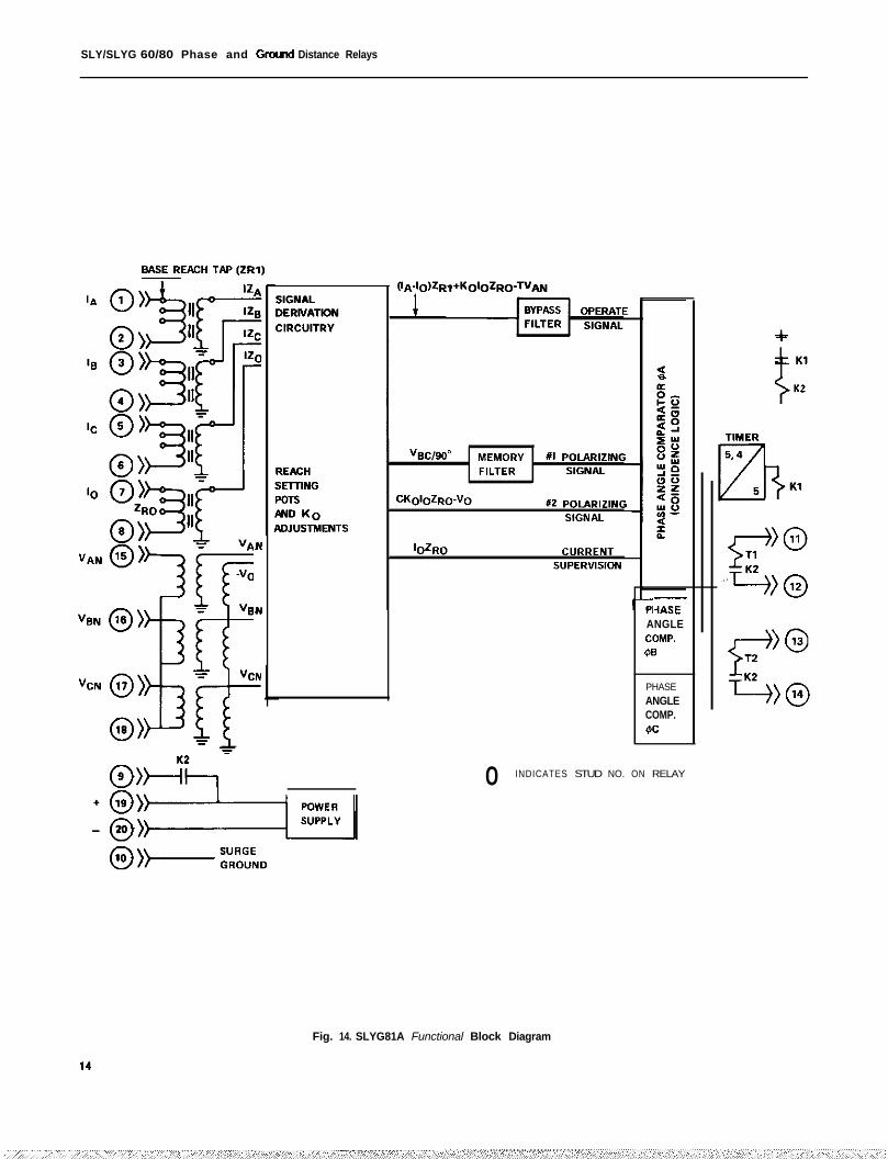
A functional block diagram of the SLYG81A trippingrelay is shown in Fig. 14. This diagram shows input currentsand voltages for all three phases, and coincidence logicsignals for phase A only. These signals are:
(IA-lO)ZRl + KoloZRo operate signal. where Kg is a
- TV~N compensating factor for theXB/X, ratio of the protectedline. and T is the percent re-straint setting.
No. 1 polarizing signal.
No. 2 polarizing signal, whereC is 0.5.
‘OZRO Current supervision signal.
In the operate signal, ID is subtracted from IA so that(If + 12) is multiplied by ZR,, and Kolo is multiplied byZRD. This permits a different impedance angle for ZB1 andZRo. The available Kg settings are 2.5, 3.0, 3.5, 4.0, or4.5.
The three line to neutral voltages are reduced by meansof a three gang precision potentiometer to produce therestraint voltage portion of the operating signal, (IZ-V).
In the second polarizing signal, Vg is obtained from abroken delta connection inside the relay.
The coincidence logic card receives the four input signalslisted above and produces an output block when all fourcard inputs are positive or all four are negative.
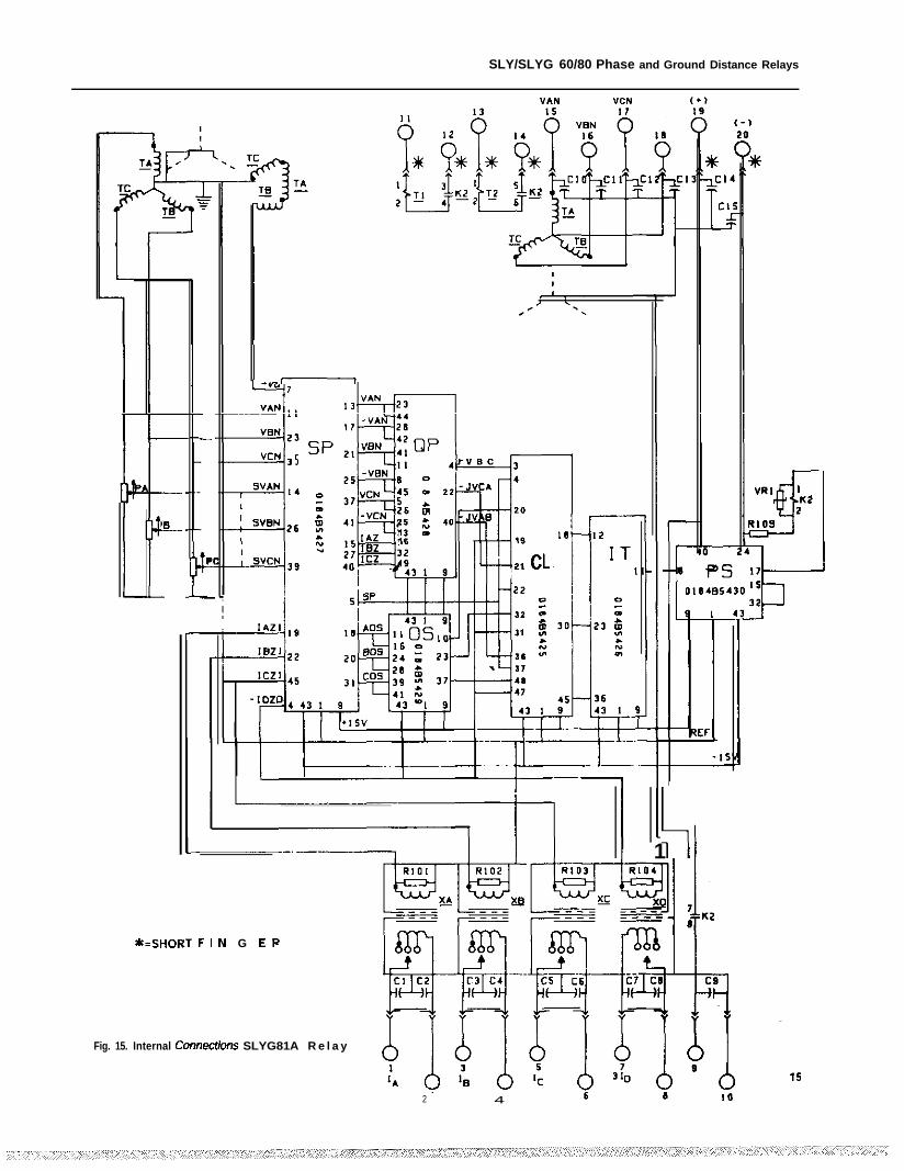
Fig. 15 is an internal connection diagram for theSLYG81A relay. The six cards in the relay are identified as:
SP Signal ProcessingQ P Quadrature PolarizingOS Operate SignalCL Coincidence LogicIT Integrating TimerPS Power Supply
Base reach lap settings are made by moving adjustableleads connected to studs 1, 3, 5, and 8 to one of three
positions. 0.1, 0.2 or 0.4 ohms for the short-reach relay,and 0.75. 1.5. or 3.0 ohms for the long-reach relay. Thepotentiometer settings marked as PA, PB. and PC are onthe ganged precision potentiometer. The Kg setting is madeby moving a jumper plug on the SP card to one of the avail-able Kg settings, which are 2.5, 3.0, 3.5, 4.0 and 4.5.
2. SLYG82 Relay (Blocking)
The SLYG82 relay is similar to the SLYG81 relay inbasic design but has two changes in the input signals to thecoincidence logic card. The No. 1 polarizing signal has anIZ quantity added to the quadrature polarizing voltage, andthe No. 2 polarizing quantity is (-‘IO) only
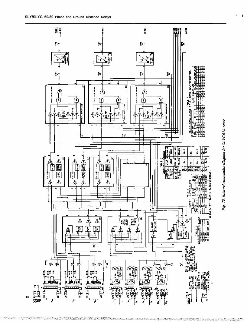
3. SLYG61A Relay
The SLYG61A relay is designed for first-zone applica-tions. The internal connection diagram for the SLYG61Arelay is shown in Fig. 16. In this diagram, card locations areshown in the lower right hand comer of the card block, andthe card-identification is given in Table 4.
Base reach settings (either 3 ohms or 1 ohm) are deter-mined by the current connections to the GA terminal blockon the back of the relay. and may be further adjusted bythe base reach multiplier (1.0, 0.5, 0.2, or 0.1) on the Ecard. The voltage restraint is adjusted by three separatepairs of tap blocks, and the D card develops the quadraturepolarizing voltage for each phase. The maximum reachimpedance angle can be changed by 10° by means of linksA, B, C and D.
The Kg selection, which is adjustable from 1.0 to 10.9in 0.1 steps, is on the G card, a s is the To selection. whichmay be either 0.0, 0.1, 0.2, 0.3. or 0.4.
The IZ and -V restraint signals are added at pins 3 and 4on the H, J, and K cards, and the polarizing voltage signals
SLY/SLYG 60/80 Phase and Gd Distance Relays
,N
IN PI
-HAS6
ANGLECOW.$B
PHASEANGLECOMP.w:
0 INDICATES STUD NO. ON RELAY
Fig. 14. SLYG81A Functional Block Diagram
-
!L
_
-
-
SLY/SLYG 60/80 Phase and Ground Distance Relays
..^I
i1
*=SHOR~ F I r4 G E R
Fig. 15. Internal Come&m SLYG81A R e l a y
2 4
SLY/SLYG 60/80 Phase and Ground Distance Relays ‘ I
r
-C---l 1 I I IL
-
SLY/SLYG 60/80 Phase and Ground Distance Relays
SLY/SLYG 60/80 Phase and Ground Distance Relays
are applied to pin 6 of these cards. The output signals onthese cards are A-C signals (both polarities) but are essenti-
ally square waves because of the high gain of the outputamplifiers on the H, J, and K cards.
The second polarizing quantity. Tg KG IoZRo-Vg is
introduced at pin 3 of the coincidence logic cards, whichrequires that all three inputs must be of the proper relativepolarity to produce an output block at pin 7.
The coincidence logic also provides for optional super-vision through the pin 8 input on the card. For example. anlo level detector in an SLC relay can be connected throughcable lead 018 to block an output if the zero sequence
current is below the 10 level detector setting.
The setting of the integrating timer determines the shapeof the relay characteristic. A setting equal to 90° (4.16 ms.at 60Hz) produces a circular characteristic.
4. SLYGGIP Relay
The SLYGGIP relay is similar to the SLYG61A relayexcept that the No. 1 polarizing quantity is tine-to-neutralplus K times positive sequence voltage. instead of quadra-ture polarizing. and the No. 2 polarizing quantity isIoZRo. This relay is intended for single-pole trippingapplications, and this change is made to prevent misopera-tion on one of the faulted phases while one pole is open.
5. SLYG62A Relay
The SLYG62A relay is designed for second-zone trippingapplications. It is similar to the SLYG61A relay except fora change in the filter design on the H, J, and K positioncards.
6. SLYG62P Relay
The SLYG62P relay is designed for second-zone applica-tion in single-pole tripping and reclosing schemes. It issimilar to the SLYG61P relay except for a change in thefilter design on the H, J, and K position cards.
7. SLYG63A Relay (Blocking)
The SLYG63A relay is similar to the SLYG62A relayexcept that the NO. 1 polarizing quantity has an IZ signaladded to it.
The No. 2 polarizing circuit has provision for an
IoZRo quantity to supplement the (-Vg) quantity, but itis recommended that a setting of To equal to zero shouldbe used on blocking relays so that the second polarizing
quantity is (-Vgl only.
8. SLYG63P Relay (Blocking)
The SLYG63P relay is similar to the SLYG62P relay
18
except that the No. 1 polarizing quantity has an IZ signal
added to it.
The No. 2 polarizing circuit has provision for an
IoZRo quantity to supplement the I-V01 quantity, but itis recommended that a setting of To equal to zero shouldbe used on blocking relays so that lhe second polarizingquantity is (-Vo) only.
APPLICATION CONSIDERATIONS, GROUND RELAYS
1. Reach Setting, First Zone Relays
The positive sequence reach of the SLYGGI or theSLYG81 relays can be set for values up to 65% of the lineimpedance if the angle of the positive sequence is 75° ormore and ii the reach does not have to be reduced due tozero sequence mutual impedance effects as described below.
The SLYG81 relay has a fixed positive sequence maxi.mum reach angle of 8S°. For lines where the positive
sequence impedance angle is less than 76°. the reactancecomponent of the line impedance should be used to esta-blish the positive sequence reach.
The SLYGGI relay provides a choice of 85° or 7 S °positive sequence and 75° or 65° zero sequence maximumreach angles. For lines that are less than 100 miles long,these guidelines are suggested for choosing the maximumreach angle: (a) for positive sequence, use 85° tap for anglesabove 80° and 75° tap for angles below 80’; (b) for zero
sequence. use 75° tap for angles above 70° and use 65° tapfor angles below 70°. For lines where the positive sequenceimpedance angle is less than 65°, the reactive componentof the line impedance should be used to establish the posi-
tive sequence reach.
The SLYGGI relay also has available a 15° leadingphase shift of the polarizing voltage, which would producean additional 15° clockwise shift of the relay characteristic.This additional phase shift is used only for specific load-flow conditions where such a shift would provide an
advantage.
The zero sequence base reach is determined by thecombination of the ZRo tap setting and the Kg setting.Usually the ZRo setting will be the same as the ZR1setting, and variations in zero sequence reach will be madeby changing KD. II there is no mutual coupling to a parallelline, the Kg setting should match the ZD/Z1 ratio of theline impedance. If there is mutual coupling. the reachsetting should be reduced to avoid overreach. See the sec.tion below on mutual impdance.
2. Reach Setting, Second Zone Relays
Second zone relays should be set to reach beyond theremote terminal of the line with substantial margin. If thereis mutual coupling from a parallel line, the zero sequence
base reach may have to be increased as described in the
SLY/SLYG 60/80 Phase and Ground Distance Relays
section below on mutual impedance. IF there is no parallelline, the setting of Kg should be approximately the sameas the zo/Zl ratio of the protected line.
IF the second zone relay is used with a timer For secondzone delayed tripping, the amount of overreach beyond theremote terminal will very likely have to be limited to pro-vide coordination with backup relays on adjacent lines. IF
the second zone relay is used only in a pilot scheme, theForward reach may be increased to obtain more Fault resis-tance coverage, keeping in mind the Fact that both thesource impedance and the Forward reach setting determinethe diameter of the no-load characteristic. For more de-
tails on Fault resistance coverage. see IEEE paper No.F78 743-7. “‘Design Considerations in the Development ofa New Ground Distance Relay” by Wilkinson. Mathewsand Keeney (GER 3089).
The Following values of reach setting as a percentage of
line length, and characteristic timer settings, are typical
values. As the line length increases, the amount of over-reach is decreased, and the operating time settings of thecharacteristic timer increase. The characteristic timersetting values are For 60 Hz applications.
Line LengthMiles
Reach% of Line
Characteristic Timer (msjFirst Pulse Steady State
O-SO ZOO 5.6 4.250-100 775 5.5 4.2
100-150 150 6.0 4.8150-200 135 6.0 5.5200-300 125 6.5 5.8
The SLYG61 and SLYG81 relays do not contain anycircuits For zero sequence mutual impedance compensation.The decision not to provide this compensation was basedon the Fact that such compensation is not effective for a
parallel line that is open and grounded at both ends. There.Fore the effect of the mutual impedance should be takeninto account when choosing the zero sequence reach settingo f the relay.
The zero sequence reach of these relays is determined by
the base reach tap. ZRo. the Kg compensation setting, andIhe restraint tap T. Usually the ZRo setting will be thesame as ZR~ (positive sequence base reach) and the Tsetting will be determined by the desired positive sequencereach. Therefore the only independent adjustment o f zerosequence reach is the Kg setting. The discussion below isaimed at choosing this setting.
In the examples given below, it is assumed that Zo ofthe protected line is 3 ohms and that Zy is 1.5 ohms. TheFirst two conditions are For parallel lines tied together at
both ends. and the next two are For lines connected to-
gether at one end only.
(a) First zone relays, both ends common
The worst case as Far as overreach is concernedwould be that of the parallel line out o f serviceand grounded at both ends. The current coupled
into the parallel line reduces the apparent impe-dance of the protected line. The apparent zero
sequence impedance is Zo
For example. if Zo= 3 and ZM = 1.5, then the
apparent impedance equals 3(1-2.25/g) or 2.25
ohms. The zero sequence apparent impedance,therefore, is 2.25/3.0 or 75% of the actual im-pedance, and the zero sequence reach of the relayshould be pulled back to 75% of the reach thatwould be used if there were no mutual effect.
(b) Second zone reach, both ends common
The condition to be considered here is that o f theparallel line in service. The apparent impedance For
the protected line in this case is ZG( )I+ %- ;a
Zo
using the typical Figures given above, Z apparent =3 (1 + 1.5/3.0) = 3 (1.5) = 4.5 ohms. Therefore4.5 ohms instead of 3 ohms should be used as thezero sequence impedance of the line in calculatinga second zone reach setting.
(c) First zone reach, one end common
2
In this case it is assumed that the current in theparallel line will flow in the opposite direction to
that in the protected line and that it will be lessthan that in the protected line. It is necessary tocalculate or assume a ratio between the currents in
the two lines. IF we let the current in the protectedline be 10 and that in the parallel line lo* then
z apparent = zoI )
lO’ZM1 - -IOZO
With the same typical values used above. and as-s u m i n g (lo’/lo) = 0.8. Z = 3 (1 - 0.8 x 1.5/3) =3 (0.60) = 1.80 ohms. Therefore the zero sequencereach should be reduced in the ratio of 1.80/3.0
ohms.
It should be noted that the positive sequence andzero sequence reach may be set independentlywithin the limits of the KG adjustment range. IF acalculation under this particular condition requires
a greater reduction in Z, reach than can be ob-tained by the available KG adjustment. then the
19
SLY/SLYG 60/80 Phase and Ground Distance Relays
positive sequence reach should be reduced untilthe desired 20 reach is obtained.
(b ) Second zone reach. one end common
If two parallel lines are permanently isolated atone end, the second zone reach setting et thecommon end should be based on the zero se-
quence impedance of the line. because the parallelline out of service gives the highest impedance.The second zone setting at the isolated end is Zo
apparent = zo10’
i )‘+ loZ#-J
In the data presented below, the basic sensitivity isgiven for a reduced reach, or pullback, error of 10%. Inaddition equations are given so that the sensitivity can be
calculated for other values of reach error.where 10 and 10’ are the currents in the protected
and the parallel lines respectively. 1. Phase Relays
However, if the lines could be temporarily con- The current sensitivity for each relay type, based onnected, es by a bus tie breaker, for-example. thenthe second zone settings should be based on the
10% reach error. is a constant IoZRf value, as given below,
calculations in paragraph (b) above.for phase-to-phase and 3-phase faults, where I,$ is phasecurrent and ZR 1 is base reach ohms:
First zone reach, both ends isolated
For this condition, the situation which wouldcause overreach would be the parallel line out ofservice and grounded et both ends. Therefore thezero sequence reach setting should be based on thecalculation in paragraph (a) on previous page.
Second zone reach, both ends isolated
If the two parallel lines are completely isolated eteach end so that there is no fault current flow inthe parallel line for a fault on the protected line.the impedance to be used as a basis for the secondzone setting would be the zero sequence of theline with no correction for mutual impedanceeffects.
$4 w
SLY61 1.0 1.15
s LY62 0.7 0.81
SLY63 0.7 0.91
SLY81 0.6 0.92
The actual current sensitivity can be determined bydividing the base reach ohms into the l,+ZR, value. Forexample, for the SLY61 relay, with a base reach of 3 ohms.and considering phase-to-phase faults. I,$ = 0.33 amperes;with a base reach of 1 ohm, I@= 1 ampere; and with a base
reach of 0.1 ohm, I+ = 10 amperes.
Coordination wilh other relays
The current sensitivity for other values of reach errorcan be calculated fmm the following equation. using theAB phase measuring unit es an example:
(I*-lgl Zff,= ;
If the second zone relays in the pilot schemeenergize second zone timers for backup protec-tion, then the second zone settings should also bechecked for the system condition which yields theminimum apparent impedance in the line to see ifthis setting coordinates with first zone relays in
adjacent lines. It may be necessary to use a com-promise setting.
where A is a constant es given below, and P is the reach
error in per unit (0.2 for 20% error).
A = 0.2 for SLY61A = 0.14 for SLY62 and 63A = 0.16 for SLY81 and 82
2. Ground Relays
R E L A Y S E N S I T I V I T Y
OPERATING CIRCUIT SENSITIVITY
The sensitivity of the operating circuit can be defined asthe lowest value of fault current that can be detected with.
out exceeding a specified error of distance measurement.
20
In mho distance relays, this is usually stated for a fault etthe maximum reach angle of the relay, and the errorcommonly used is 10%. In other words. the actual relayreach will be no less then 90% of the reach setting at thestated current level.
The current sensitivity value is a function of the basereach tap (in the 90 series) or the base reach setting (in the
60 series) and is not affected by the restraint tap used.
The calculation of current sensitivity for ground distancerelays is more complex because it is affected by the ratio ofzero sequence current to positive sequence current and by
the value of KG.
The basic current sensitivity values given below, in terms
of l$ZRl, assume that the reach error is 10%. that I0 =
310 that KG= 3. and that Z,q, = 2RO.
SLY/SLYG 60/80 Phase and Ground Distance Relays
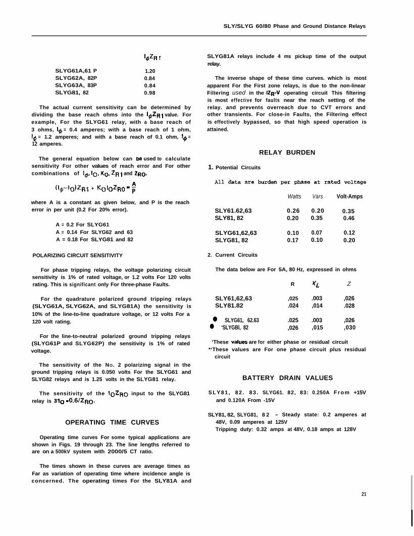
‘#I7 1
SLYG61A,61 P 1.20SLYG62A, 82P 0.84SLYG63A, 83P 0.84SLYG81, 82 0.98
The actual current sensitivity can be determined bydividing the base reach ohms into the l&j value. Forexample, For the SLYG61 relay, with a base reach of
3 ohms, I,$ = 0.4 amperes; with a base reach of 1 ohm,1~~ = 1.2 amperes; and with a base reach of 0.1 ohm, 16 =12 amperes.
The general equation below can be used to calculatesensitivity For other values of reach error and For othercombinations of ‘@lo, KU, ZRJ and ZRU.
(I~-IGlZRl + KGlGZRo=;
where A is a constant as given below, and P is the reacherror in per unit (0.2 For 20% error).
A = 0.2 For SLYG61
A = 0.14 For SLYG62 and 63A = 0.18 For SLYG81 and 82
POLARIZING CIRCUIT SENSITIVITY
For phase tripping relays, the voltage polarizing circuitsensitivity is 1% of rated voltage, or 1.2 volts For 120 voltsrating. This is significant only For three-phase Faults.
For the quadrature polarized ground tripping relays(SLYG61A, SLYG62A, and SLYG81A) the sensitivity is
10% of the line-to-line quadrature voltage, or 12 volts For a
120 volt rating.
For the line-to-neutral polarized ground tripping relays(SLYG61P and SLYG62P) the sensitivity is 1% of ratedvoltage.
The sensitivity of the NO. 2 polarizing signal in theground tripping relays is 0.050 volts For the SLYG61 andSLYG82 relays and is 1.25 volts in the SLYG81 relay.
The sensitivity of the IGZRG input to the SLYG81
relay is 310 =0.6/ZRo.
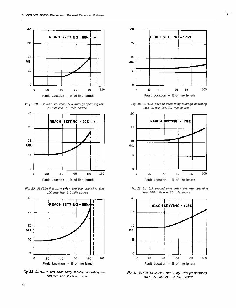
OPERATING TIME CURVES
Operating time curves For some typical applications areshown in Figs. 19 through 23. The line lengths referred toare on a 500kV system with 2000/5 CT ratio.
The times shown in these curves are average times as
Far as variation of operating time where incidence angle isconcerned. The operating times For the SLY81A and
SLYG81A relays include 4 ms pickup time of the output
relay.
The inverse shape of these time curves. which is most
apparent For the First zone relays, is due to the non-linearFiltering used in the IZR.V operating circuit This filteringis most effective for faults near the reach setting of therelay. and prevents overreach due to CVT errors andother transients. For close-in Faults, the Filtering effect
is effectively bypassed, so that high speed operation isattained.
RELAY BURDEN
1. Potential Circuits
Watts Vars Volt-Amps
SLY61.62,63 0.26 0.20 0.35SLY81, 82 0.20 0.35 0.46
SLYG61,62,63 0.10 0.07 0.12SLYG81, 82 0.17 0.10 0.20
2. Current Circuits
The data below are For 5A, 80 Hz, expressed in ohms
R XL Z
SLY61,62,63 ,025 .003 ,026SLY81.82 .024 ,014 .028
l SLYG61, 62.63 .025 .003 ,026l ‘SLYGBl, 82 ,026 ,015 ,030
‘These v&es are for either phase or residual circuit*‘These values are For one phase circuit plus residual
circuit
BATTERY DRAIN VALUES
S L Y 8 1 , 8 2 . 8 3 . SLYG61. 82, 83: 0.250A F r o m +15V
and 0.120A From -15V
SLY81, 82, SLYG81, 8 2 - Steady state: 0.2 amperes at48V, 0.09 amperes at 125VTripping duty: 0.32 amps at 48V, 0.18 amps at 128V
21
SLY/SLYG 60/80 Phase and Ground Distance. Relays.
10
0
0 20 40 60 80 100
Fault Location - % of line length
Fig. 18. SLY61A first zone relay average operating lime75 mile line, 2 5 mile source
40
2 0
15
10
MS.
5
0
0 20 40 60 80 100
Fault Location - % of line length
Fig. 19. SLY62A second zone relay average operatingtime 75 mile line, 25 mile source
20
30 15
10
MS.
10 5
00 20 4 0 60 8 0 100
Fault Location - % of line length
Fig. 20. SLY81A first zone r&y average operating time100 mile line, 2 5 mile source
40
0
0 20 40 60 80 100
Fault Location - % of line length
Fig. 21. SL Y81A second zone relay average operatingtime 700 mile he. 25 mile source
20
30 15
0
0 20 4 0 60 80 100
Fault Location - % of line length
0
0 20 40 60 80 100
Fault Location - % of line length
22
SLY/SLYG 60/80 Phase and Ground Distance Relays
RELAY SCHEMES
These relays may be used in a number of different
schemes, including step-distance protection without apilot channel. or directional comparison with a pilotchannel. Directional comparison includes blocking schemes
and permissive tripping schemes, and may be used withON-OFF power line carrier, frequency shift power linecarrier, or microwave channels. Direct trip functions maybe included as part of the schemes.
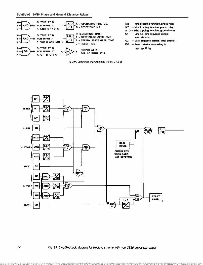
Three typical schemes are shown in Figs. 24. 25, and 26.A legend of logic diagram symbols is shown in Fig. 24A.
Figure 24 is a simplified logic diagram showing theSLY62, SLY63, SLYG62 and SLC51 relays in a directional
comparison blocking scheme using Type CS26 OFF-ONpower line carrier. This scheme uses overcurrent carrierstarting (G1) for all faults involving ground, and distancerelay carrier start (MB) for phase faults.
In this scheme, for external ground faults. MTG at one
end of the line will see the fault in the tripping directionand will operate to stop carrier transmission from that endvia OR-7 and the NOT input to AND-6. At the other end.MTG will not operate. and the blocking carrier transmissionwill continue. blocking the end where MTG has operated.
For external phase faults. carrier is transmitted onlyfrom the end closest to the fault, where MB, and not MT.has operated. This sends a blocking signal to the remoteend. where MT has operated. and prevents it from tripping.
For internal ground faults, MTG (and/or MT) at bothends will operate to stop carrier transmission and to pro-duce a pilot trip output. For internal phase faults. thedesign of MT and MB is coordinated so that MT is alwaysfaster than MB for those fault locations that are within theMB steady-state characteristic. Therefore carrier transmis-sion is either stopped or prevented for all internal faults.
Another feature of this scheme is transient blocking.which prevents incorrect tripping on the clearing of anexternal fault. The method of providing transient blockingis different for phase and ground relay operation. as des-
cribed below.
For external phase faults, where MB operates and MTdoes not. the output of MB is continued for 30 ms after thefault is cleared. This 30 ms reset time prevents the trippingfunctions from initiating a pilot trip, and prevents carrierfrom being stopped during that period.
For external ground faults. G1 at each end will start
carrier. apply the NOT input to AND-16 to block pilottripping, and energize timer TL-4 via AND-5. Timer TL-4will operate in 25 ms, before the external fault is cleared.When the fault is cleared and G1 resets, TL-4 output isextended for 35 ms by the reset delay of TL-4. If the faultwas on a parallel line, and clearing of one end caused a
reversal of the direction of fault current flow over the line,MTG at one end may operate before MTG has reset at theother end. and transient blocking will prevent false tripping
for this condition.
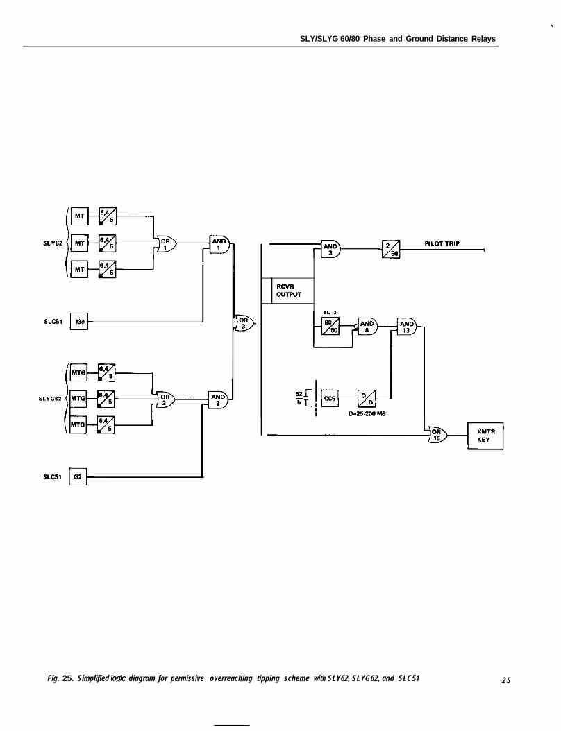
Figure 25 is a simplified logic diagram for a permissivetripping scheme using the SLY62 and SLYG62 relays.Either MT or MTG key the transmitter to send permission
to the opposite terminal. and they also provide a local tripsignal to AND-3. A trip output is obtained when there is alocal trip signal and a receiver output signal at AND-3 formore than 2 ms.
An additional feature of this particular scheme is therepeat (or echo) keying of the transmitter via TL-3. AND-O.and AND-13 if the breaker is open at one end of the line.This permits tripping via the pilot protection when closinginto a faulted line.
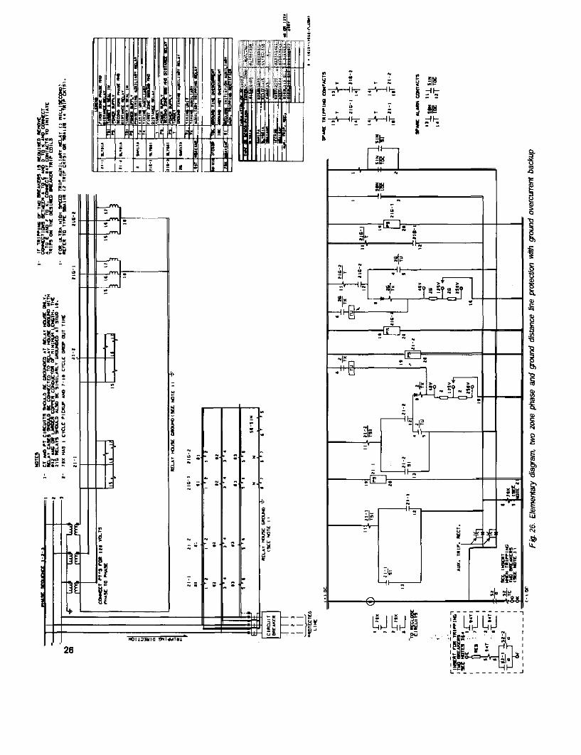
Figure 26 is an elementary diagram for a two zonestepped distance relaying scheme using the SLY81 andSLYG81 relays. This permits direct tripping and recloseinitiation for the first zone relays, and delayed tripping forfaults detected by the second zone relays.
23
SLY/SLYG 60/80 Phase and Ground Distance Relays
r
SLY/SLYG 60/80 Phase and Ground Distance Relays
Fig. 25. Simplified logic diagram for permissive overreaching tipping scheme with SLY62, SLYG62, and SLC51 2 5
’ ‘26