Embed Size (px)
Citation preview
EE589EE589--Power System Quality & HarmonicsPower System Quality & HarmonicsDr. E. A. Dr. E. A. FeilatFeilatElectrical Engineering DepartmentElectrical Engineering DepartmentSchool of EngineeringSchool of EngineeringUniversity of JordanUniversity of Jordan
POWER SYSTEMS QUALITYPOWER SYSTEMS QUALITY Topic 5: Topic 5: Principles for Controlling HarmonicsPrinciples for Controlling Harmonics
Dr. E. A. Feilat 1
Control of Harmonics
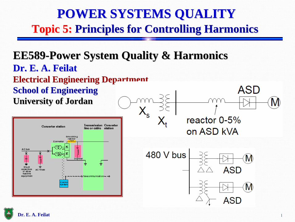
Two common causes of harmonic problemsNonlinear loads injecting excessive harmonic currentsInteraction between harmonic currents and the system
frequency.
Dr. E. A. Feilat 2
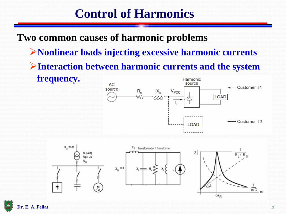
When a problem occurs, the basic options for controlling harmonics are:
1.
Reduce the harmonic currents produced by the load.2.
Add filters to either siphon the harmonic currents off the system, block the currents from entering the system, or supply the harmonic currents locally.
3.
Modify the frequency response of the system by filters, inductors, or capacitors.
Principles for Controlling HarmonicsPrinciples for Controlling Harmonics
Dr. E. A. Feilat 3
4
1. Adding a line reactor or transformer in series will significantly reduce harmonics, as well as provide transient protection benefits.
2. Transformer connections can be employed to reduce harmonic currents in three-phase systems.
I. Phase-shifting half of the 6-pulse power converters in a plant load by 30o
can approximate the benefits of 12-pulse loads by dramatically reducing the fifth and seventh harmonics.
II.
Delta-connected transformers can block the flow of zero- sequence harmonics (typically triplens) from the line.
III.
Zigzag and grounding transformers can shunt the triplens off the line.
1. Reducing harmonic Currents in Loads
Dr. E. A. Feilat
5
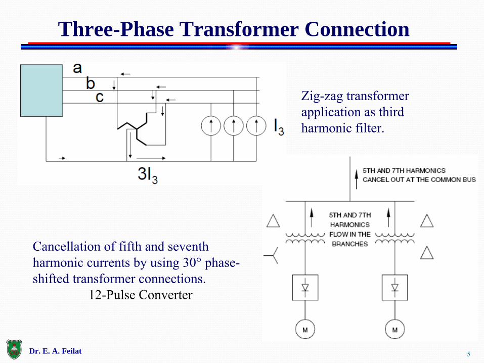
Three-Phase Transformer Connection
Zig-zag
transformer application as third harmonic filter.
Cancellation of fifth and seventh harmonic currents by using 30°
phase-
shifted transformer connections.12-Pulse Converter
Dr. E. A. Feilat
6
1. The shunt filter works by short-circuiting harmonic currents as close to the source of distortion as practical.
I. This keeps the currents out of the supply system.
II.
The most common type of filtering applied because of economics and because it also tends to correct the load power factor as well as remove the harmonic current.
2. Another approach is to apply a series filter that blocks the harmonic currents.
I. This is a parallel-tuned circuit that offers a high impedance to the harmonic current.
3. Active filters work by electronically supplying the harmonic component of the current into a nonlinear load.
2. Filtering
Dr. E. A. Feilat
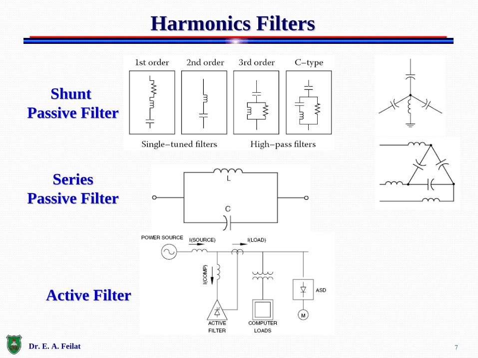
Harmonics FiltersHarmonics Filters
Shunt Shunt Passive FilterPassive Filter
SeriesSeriesPassive FilterPassive Filter
Active FilterActive Filter
Dr. E. A. Feilat 7
8
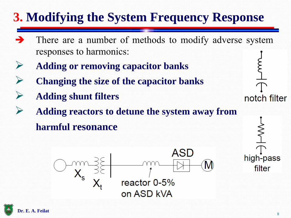
There are a number of methods to modify adverse system responses to harmonics:
Adding or removing capacitor banks
Changing the size of the capacitor banks
Adding shunt filters
Adding reactors to detune the system away from harmful resonance
3. Modifying the System Frequency Response
Dr. E. A. Feilat
9
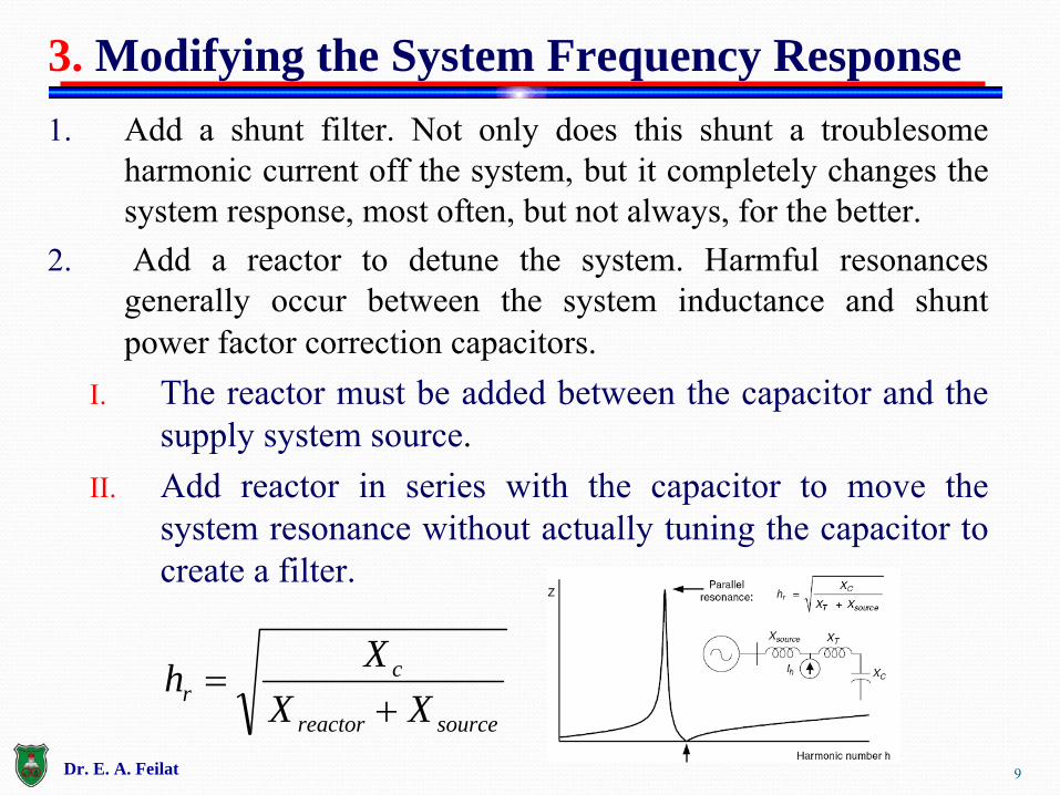
1. Add a shunt filter. Not only does this shunt a troublesome harmonic current off the system, but it completely changes the system response, most often, but not always, for the better.
2. Add a reactor to detune the system. Harmful resonances
generally occur between the system inductance and shunt power factor correction capacitors.
I.
The reactor must be added between the capacitor and the supply system source.
II.
Add reactor in series with the capacitor to move the system resonance without actually tuning the capacitor to create a filter.
3. Modifying the System Frequency Response
sourcereactor
cr XX
Xh
Dr. E. A. Feilat

10
3. Change the capacitor size. This is often one of the least expensive options for both utilities and industrial customers.
4. Move a capacitor to a point on the system with a different short-circuit impedance or higher losses.
5. Remove the capacitor and simply accept the higher losses, lower voltage, and power factor penalty. If technically feasible, this is occasionally the best economic choice.
3. Modifying the System Frequency Response
SC
c
C
scr X
XQ
MVAh
Dr. E. A. Feilat
11
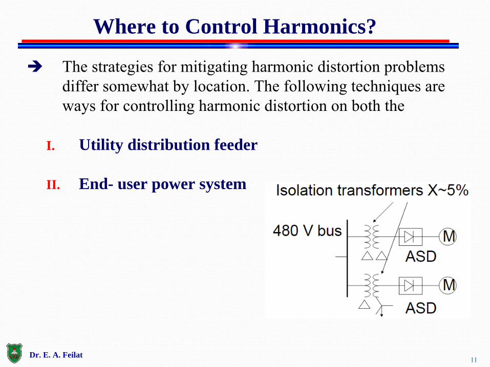
The strategies for mitigating harmonic distortion problems differ somewhat by location. The following techniques are ways for controlling harmonic distortion on both the
I. Utility distribution feeder
II. End- user power system
Where to Control Harmonics?
Dr. E. A. Feilat
12
● The
X/R ratio of a utility distribution feeder is generally low.
Therefore, the magnification of harmonics by resonance with feeder banks is usually minor in comparison to what might be found inside an industrial facility.
● Utility distribution engineers are accustomed to placing feeder banks where they are needed without concern about harmonics.
● However, voltage distortion from the resonance of feeder banks may exceed limits in a few cases and require mitigation.
● When problems do occur, the usual strategy is to first attempt a solution by moving the offending bank or changing the capacitor size or neutral connection.
Solution On Utility Distribution Feeders
Dr. E. A. Feilat
13
Some harmonic problems associated with feeder capacitor banks are due to increasing the triplen
harmonics in the neutral
circuit of the feeder.
To change the flow of zero-sequence harmonic currents, changes are made to the neutral connection of Y-connected banks.
To block the flow, the neutral is allowed to float (Ungrounded).
In other cases, it is more advantageous to aid the flow by putting a reactor in the neutral to convert the bank into a tuned resonant shunt for a zero-sequence harmonic.
Solution On Utility Distribution Feeders
Dr. E. A. Feilat

14
Harmonic problems on distribution feeders often exist only at light load.
The voltage rises, causing the distribution transformers to produce more harmonic currents and there is less load to damp out resonance.
Switching the capacitors off at this time frequently solves the problem.
Solution On Utility Distribution Feeders
Dr. E. A. Feilat

15
● When harmonic problems arise in an end-user facility, the first step is to determine if the main cause is resonance with power factor capacitors in the facility.
● When it is, first attempt a simple solution by using a different
capacitor size. ●
With automatic power factor controllers, it may be possible to select a control scheme that avoids the configuration that causes problems.
● In other cases, there will be so many capacitors switched at random with loads that it will be impossible to avoid resonant conditions.
● Filtering will be necessary.
Solution In end-user Facilities
Dr. E. A. Feilat
16
● Installation of filters on end-user low-voltage systems is generally more practical and economical than on utility distribution systems. The criteria for filter installation are more easily met, and filtering equipment is more readily available on
the market.●
When the magnitude of harmonic currents injected by loads is excessive, industrial users should also investigate means of reducing harmonics by using different transformer connections and line chokes.
● In office buildings, zigzag transformers and triplen
harmonic
filters can reduce the impact of triplen
harmonic currents on neutral circuits.
Solution In end-user Facilities
17
● Installation of filters on end-user low-voltage systems is generally more practical and economical than on utility distribution systems. The criteria for filter installation are more easily met, and filtering equipment is more readily available on
the market.●
When the magnitude of harmonic currents injected by loads is excessive, industrial users should also investigate means of reducing harmonics by using different transformer connections and line chokes.
● In office buildings, zigzag transformers and triplen
harmonic
filters can reduce the impact of triplen
harmonic currents on neutral circuits.
Solution In end-user Facilities
Dr. E. A. Feilat

18
● A simple, but often successful, method to control harmonic distortion generated by adjustable-speed drives involves a relatively small reactor, or choke, inserted at the line input side of the drive. This is particularly effective for PWM-type drives.
● A typical 3% input choke can reduce the harmonic current distortion for a PWM-type drive from approximately 80% to 40% percent.
● The choke size is computed on the drive kVA
base.
● Isolation transformers can provide the same benefit as a choke but may be more costly. However, isolation transformers with multiple drives offer the advantage of creating effective 12-pulse operation.
In-line Reactors or Chokes
Dr. E. A. Feilat

19
● A typical 3% input choke can reduce the harmonic current distortion for a PWM-type drive from approximately 80% to 40% percent.
In-line Reactors or Chokes
Typical line chokes used in 480-V ASD applications
Dr. E. A. Feilat
20
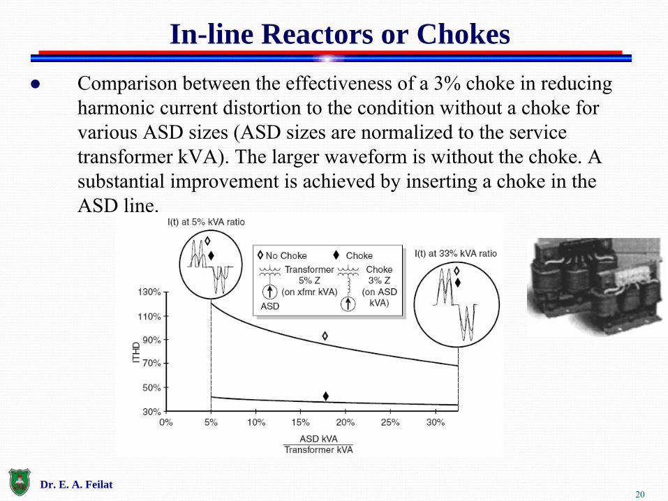
● Comparison between the effectiveness of a 3% choke in reducing harmonic current distortion to the condition without a choke for
various ASD sizes (ASD sizes are normalized to the service transformer kVA). The larger waveform is without the choke. A substantial improvement is achieved by inserting a choke in the ASD line.
In-line Reactors or Chokes
Dr. E. A. Feilat

21
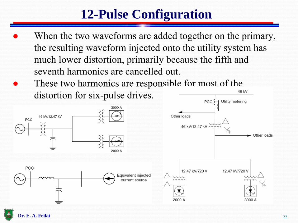
● A 12-pulse configuration can be achieved by supplying one drive through a -Y connected transformer, and another drive through a -
connected transformer.
12-Pulse Configuration
Current waveforms for two separate six-pulse ASDs.
Dr. E. A. Feilat
22
● When the two waveforms are added together on the primary, the resulting waveform injected onto the utility system has much lower distortion, primarily because the fifth and seventh harmonics are cancelled out.
● These two harmonics are responsible for most of the distortion for six-pulse drives.
12-Pulse Configuration
Dr. E. A. Feilat

23
Zigzag transformers are often applied in commercial facilities to control zero-sequence harmonic components.
A zigzag transformer acts like a filter to the zero-sequence current by offering a low-impedance path to neutral.
This reduces the amount of current that flows in the neutral back toward the supply by providing a shorter path for the current.
To be effective, the transformer must be located near the load on the circuit that is being protected drives.
Zigzag Transformers
Dr. E. A. Feilat
24
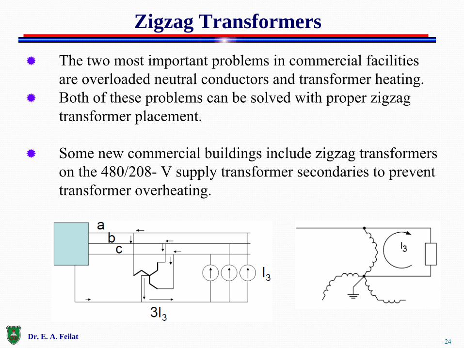
The two most important problems in commercial facilities are overloaded neutral conductors and transformer heating.
Both of these problems can be solved with proper zigzag transformer placement.
Some new commercial buildings include zigzag transformers on the 480/208-
V supply transformer secondaries
to prevent
transformer overheating.
Zigzag Transformers
Dr. E. A. Feilat
25
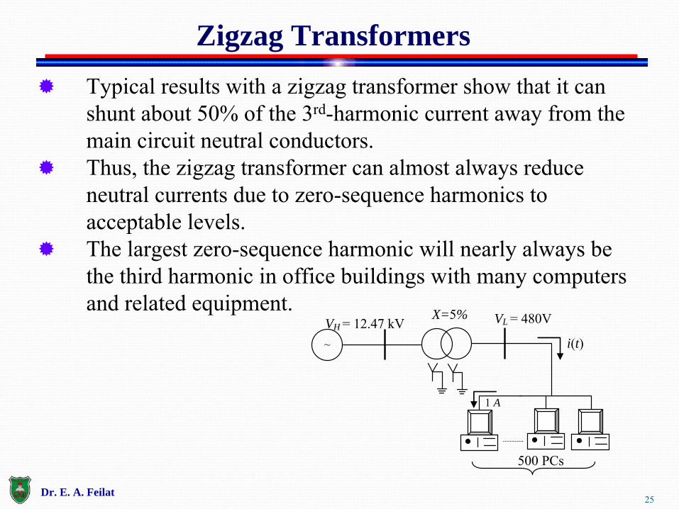
Typical results with a zigzag transformer show that it can shunt about 50% of the 3rd-harmonic current away from the main circuit neutral conductors.
Thus, the zigzag transformer can almost always reduce neutral currents due to zero-sequence harmonics to acceptable levels.
The largest zero-sequence harmonic will nearly always be the third harmonic in office buildings with many computers and related equipment.
Zigzag Transformers
~ i(t)
VL = 480V VH = 12.47 kV X=5%
1 A
500 PCs
Dr. E. A. Feilat


![Standby Power Systems - UNSJdea.unsj.edu.ar/ihospitalarias/Power Quality in... · assembled into standby power systems for critical loads and systems. They include the following [13.1]:](https://img.pdfslide.net/doc/110x75/5eb7ec6a44b6e07038322bc3/standby-power-systems-quality-in-assembled-into-standby-power-systems-for.jpg)