Embed Size (px)
Citation preview
PowerFlex 520-Series AC Drives
The Next Generation of Powerful Performance. Flexible Control.
PowerFlex 520-Series AC DrivesThe Next Generation of Powerful Performance. Flexible Control.
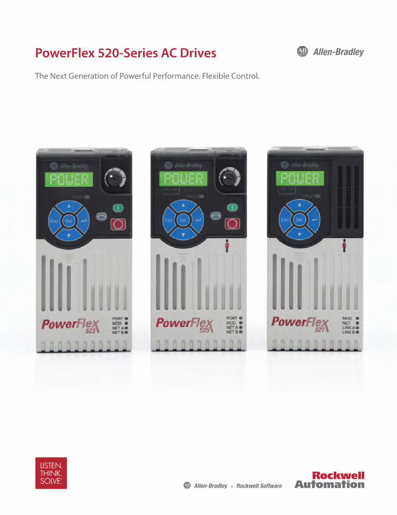
Allen-Bradley® PowerFlex® 520-Series AC drives combine innovation and ease of use to provide motor control solutions designed to maximize your system performance and reduce your time to design and deliver better machines. Each of the three drives in this family offers a unique set of features to distinctively match the needs of your application.
PowerFlex 523 AC drives are ideal for machines that require cost-effective motor control.
PowerFlex 525 AC drives are ideal for machines with simple system integration and offer standard features including built-in EtherNet/IP™ and safety.
PowerFlex 527 AC drives are designed to be used with an Allen-Bradley Logix Programmable Automation Controller (PAC). Ideal for machines that can benefit from the same drive configuration experience for both servo and AC drives, the PowerFlex 527 drive features a built-in dual port for EtherNet/IP and safety over the network.
2
PowerFlex 520-Series AC DrivesThe Next Generation of Powerful Performance. Flexible Control.
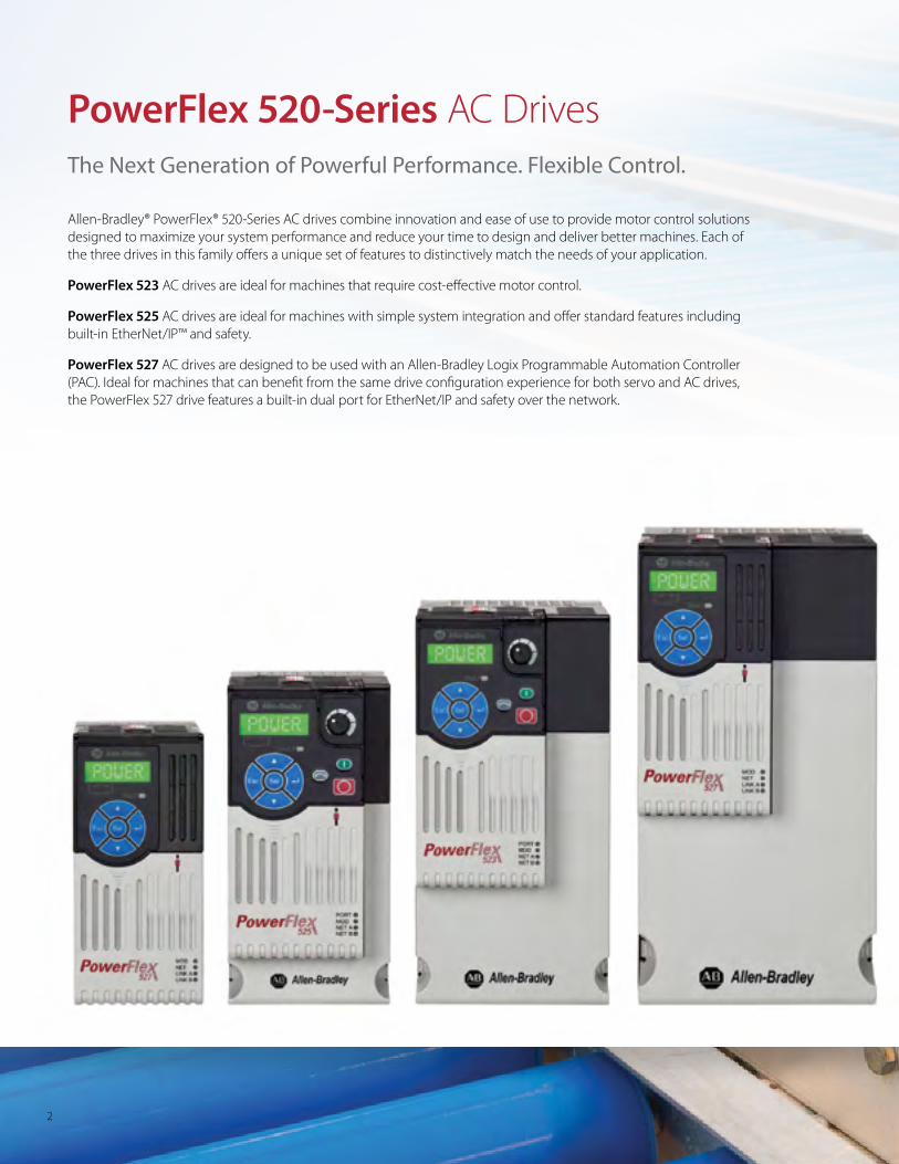
PowerFlex 520-Series AC drives are designed to help maximize your productivity both in machine design and in use.
• Power ratings
– PowerFlex 523 AC drives: 0.2...22 kW / 0.25...30 Hp in global voltage classes from 100-600V
– PowerFlex 525 AC drives: 0.4...22 kW / 0.5...30 Hp in global voltage classes from 100-600V
– PowerFlex 527 AC drives: 0.4...22 kW / 0.5...30 Hp in global voltage classes from 100-600V
• The modular design helps reduce spare parts inventory and provides a faster way to install and configure drives
• EtherNet/IP connectivity supports seamless integration into the Logix environment
• Built-in safety features for PowerFlex 525 and 527 drives help protect personnel and assets
• The PowerFlex 527 offers Integrated Safety – safety via an EtherNet/IP network
• A choice of easy-to-use software and tools helps simplify design, configuration and programming
• High operating temperatures of up to 50°C (122°F). With current derating and a control module fan kit, up to 70°C (158°F)
• Save panel space with a compact footprint that provides flexible installation
3
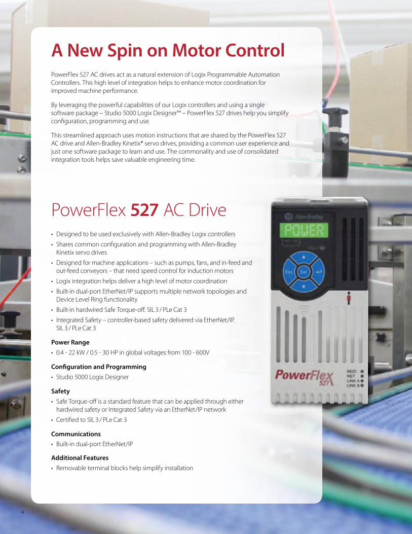
PowerFlex 527 AC Drive• Designed to be used exclusively with Allen-Bradley Logix controllers
• Shares common configuration and programming with Allen-Bradley Kinetix servo drives
• Designed for machine applications – such as pumps, fans, and in-feed and out-feed conveyors – that need speed control for induction motors
• Logix integration helps deliver a high level of motor coordination
• Built-in dual-port EtherNet/IP supports multiple network topologies and Device Level Ring functionality
• Built-in hardwired Safe Torque-off. SIL 3 / PLe Cat 3
• Integrated Safety – controller-based safety delivered via EtherNet/IP. SIL 3 / PLe Cat 3
Power Range• 0.4 - 22 kW / 0.5 - 30 HP in global voltages from 100 - 600V
Configuration and Programming• Studio 5000 Logix Designer
Safety• Safe Torque-off is a standard feature that can be applied through either
hardwired safety or Integrated Safety via an EtherNet/IP network
• Certified to SIL 3 / PLe Cat 3
Communications• Built-in dual-port EtherNet/IP
Additional Features• Removable terminal blocks help simplify installation
A New Spin on Motor Control PowerFlex 527 AC drives act as a natural extension of Logix Programmable Automation Controllers. This high level of integration helps to enhance motor coordination for improved machine performance.
By leveraging the powerful capabilities of our Logix controllers and using a single software package – Studio 5000 Logix Designer™ – PowerFlex 527 drives help you simplify configuration, programming and use.
This streamlined approach uses motion instructions that are shared by the PowerFlex 527 AC drive and Allen-Bradley Kinetix® servo drives, providing a common user experience and just one software package to learn and use. The commonality and use of consolidated integration tools helps save valuable engineering time.
4
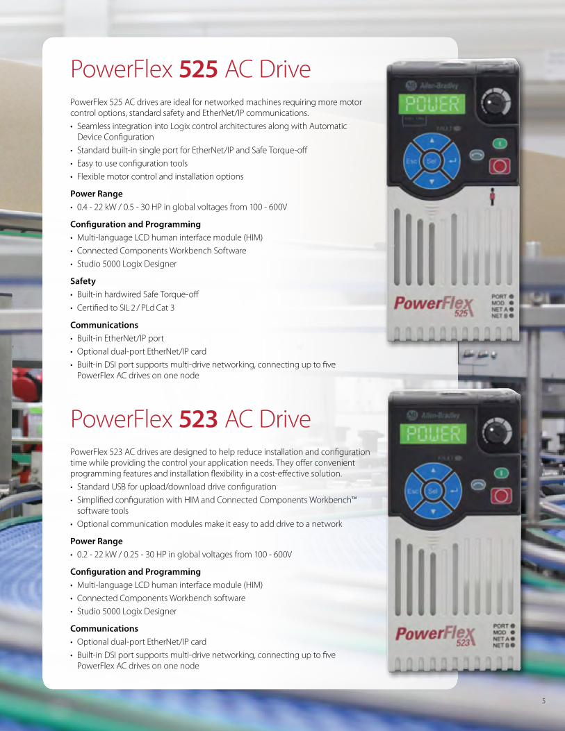
PowerFlex 525 AC DrivePowerFlex 525 AC drives are ideal for networked machines requiring more motor control options, standard safety and EtherNet/IP communications.
• Seamless integration into Logix control architectures along with Automatic Device Configuration
• Standard built-in single port for EtherNet/IP and Safe Torque-off
• Easy to use configuration tools
• Flexible motor control and installation options
Power Range• 0.4 - 22 kW / 0.5 - 30 HP in global voltages from 100 - 600V
Configuration and Programming• Multi-language LCD human interface module (HIM)
• Connected Components Workbench Software
• Studio 5000 Logix Designer
Safety• Built-in hardwired Safe Torque-off
• Certified to SIL 2 / PLd Cat 3
Communications• Built-in EtherNet/IP port
• Optional dual-port EtherNet/IP card
• Built-in DSI port supports multi-drive networking, connecting up to five PowerFlex AC drives on one node
PowerFlex 523 AC DrivePowerFlex 523 AC drives are designed to help reduce installation and configuration time while providing the control your application needs. They offer convenient programming features and installation flexibility in a cost-effective solution.
• Standard USB for upload/download drive configuration
• Simplified configuration with HIM and Connected Components Workbench™ software tools
• Optional communication modules make it easy to add drive to a network
Power Range • 0.2 - 22 kW / 0.25 - 30 HP in global voltages from 100 - 600V
Configuration and Programming• Multi-language LCD human interface module (HIM)
• Connected Components Workbench software
• Studio 5000 Logix Designer
Communications• Optional dual-port EtherNet/IP card
• Built-in DSI port supports multi-drive networking, connecting up to five PowerFlex AC drives on one node
5
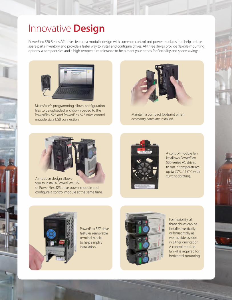
Innovative DesignPowerFlex 520-Series AC drives feature a modular design with common control and power modules that help reduce spare parts inventory and provide a faster way to install and configure drives. All three drives provide flexible mounting options, a compact size and a high temperature tolerance to help meet your needs for flexibility and space savings.
Maintain a compact footprint when accessory cards are installed.
A modular design allows you to install a PowerFlex 525 or PowerFlex 523 drive power module and configure a control module at the same time.
MainsFree™ programming allows configuration files to be uploaded and downloaded to the PowerFlex 525 and PowerFlex 523 drive control module via a USB connection.
A control module fan kit allows PowerFlex 520-Series AC drives to run in temperatures up to 70°C (158°F) with current derating.
For flexibility, all three drives can be installed vertically or horizontally as well as side by side in either orientation. A control module fan kit is required for horizontal mounting.
PowerFlex 527 drive features removable terminal blocks to help simplify installation.
6
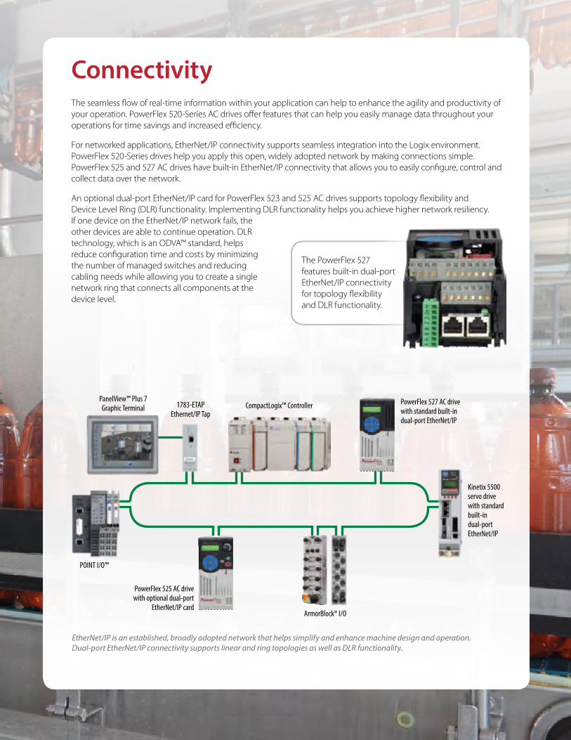
PowerFlex 525 AC drive with optional dual-port
EtherNet/IP card
PowerFlex 527 AC drive with standard built-in dual-port EtherNet/IP
Kinetix 5500 servo drive with standard built-in dual-port EtherNet/IP
POINT I/O™
1783-ETAPEthernet/IP Tap
ArmorBlock® I/O
CompactLogix™ ControllerPanelView™ Plus 7 Graphic Terminal
ConnectivityThe seamless flow of real-time information within your application can help to enhance the agility and productivity of your operation. PowerFlex 520-Series AC drives offer features that can help you easily manage data throughout your operations for time savings and increased efficiency.
For networked applications, EtherNet/IP connectivity supports seamless integration into the Logix environment. PowerFlex 520-Series drives help you apply this open, widely adopted network by making connections simple. PowerFlex 525 and 527 AC drives have built-in EtherNet/IP connectivity that allows you to easily configure, control and collect data over the network.
An optional dual-port EtherNet/IP card for PowerFlex 523 and 525 AC drives supports topology flexibility and Device Level Ring (DLR) functionality. Implementing DLR functionality helps you achieve higher network resiliency. If one device on the EtherNet/IP network fails, the other devices are able to continue operation. DLR technology, which is an ODVA™ standard, helps reduce configuration time and costs by minimizing the number of managed switches and reducing cabling needs while allowing you to create a single network ring that connects all components at the device level.
The PowerFlex 527 features built-in dual-port EtherNet/IP connectivity for topology flexibility and DLR functionality.
EtherNet/IP is an established, broadly adopted network that helps simplify and enhance machine design and operation. Dual-port EtherNet/IP connectivity supports linear and ring topologies as well as DLR functionality.
7
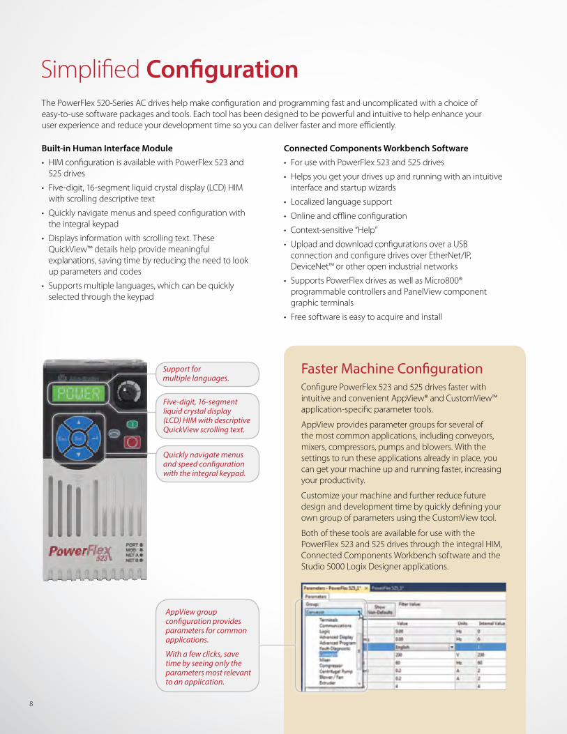
The PowerFlex 520-Series AC drives help make configuration and programming fast and uncomplicated with a choice of easy-to-use software packages and tools. Each tool has been designed to be powerful and intuitive to help enhance your user experience and reduce your development time so you can deliver faster and more efficiently.
Built-in Human Interface Module• HIM configuration is available with PowerFlex 523 and
525 drives
• Five-digit, 16-segment liquid crystal display (LCD) HIM with scrolling descriptive text
• Quickly navigate menus and speed configuration with the integral keypad
• Displays information with scrolling text. These QuickView™ details help provide meaningful explanations, saving time by reducing the need to look up parameters and codes
• Supports multiple languages, which can be quickly selected through the keypad
Faster Machine ConfigurationConfigure PowerFlex 523 and 525 drives faster with intuitive and convenient AppView® and CustomView™ application-specific parameter tools.
AppView provides parameter groups for several of the most common applications, including conveyors, mixers, compressors, pumps and blowers. With the settings to run these applications already in place, you can get your machine up and running faster, increasing your productivity.
Customize your machine and further reduce future design and development time by quickly defining your own group of parameters using the CustomView tool.
Both of these tools are available for use with the PowerFlex 523 and 525 drives through the integral HIM, Connected Components Workbench software and the Studio 5000 Logix Designer applications.
Connected Components Workbench Software• For use with PowerFlex 523 and 525 drives
• Helps you get your drives up and running with an intuitive interface and startup wizards
• Localized language support
• Online and offline configuration
• Context-sensitive “Help”
• Upload and download configurations over a USB connection and configure drives over EtherNet/IP, DeviceNet™ or other open industrial networks
• Supports PowerFlex drives as well as Micro800® programmable controllers and PanelView component graphic terminals
• Free software is easy to acquire and install
Simplified Configuration
Support for multiple languages.
Quickly navigate menus and speed configuration with the integral keypad.
Five-digit, 16-segment liquid crystal display (LCD) HIM with descriptive QuickView scrolling text.
AppView group configuration provides parameters for common applications.
With a few clicks, save time by seeing only the parameters most relevant to an application.
8
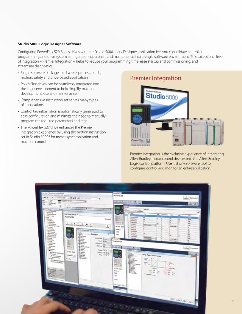
Studio 5000 Logix Designer Software
Configuring PowerFlex 520-Series drives with the Studio 5000 Logix Designer application lets you consolidate controller programming and drive system configuration, operation, and maintenance into a single software environment. This exceptional level of integration – Premier Integration – helps to reduce your programming time, ease startup and commissioning, and streamline diagnostics.
• Single software package for discrete, process, batch, motion, safety and drive-based applications
• PowerFlex drives can be seamlessly integrated into the Logix environment to help simplify machine development, use and maintenance
• Comprehensive instruction set serves many types of applications
• Control tag information is automatically generated to ease configuration and minimize the need to manually program the required parameters and tags
• The PowerFlex 527 drive enhances the Premier Integration experience by using the motion instruction set in Studio 5000® for motor synchronization and machine control
Premier Integration is the exclusive experience of integrating Allen-Bradley motor control devices into the Allen-Bradley Logix control platform. Use just one software tool to configure, control and monitor an entire application.
Premier Integration
9
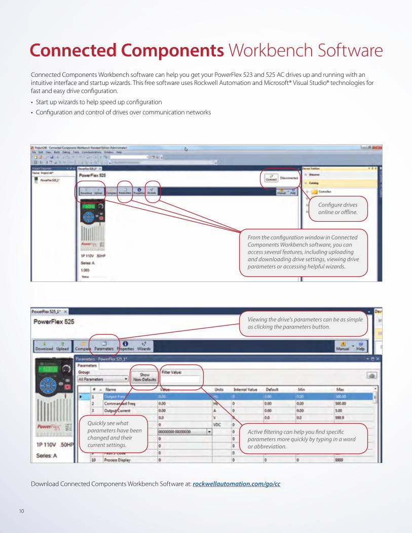
Connected Components Workbench SoftwareConnected Components Workbench software can help you get your PowerFlex 523 and 525 AC drives up and running with an intuitive interface and startup wizards. This free software uses Rockwell Automation and Microsoft® Visual Studio® technologies for fast and easy drive configuration.
• Start up wizards to help speed up configuration
• Configuration and control of drives over communication networks
From the configuration window in Connected Components Workbench software, you can access several features, including uploading and downloading drive settings, viewing drive parameters or accessing helpful wizards.
Viewing the drive’s parameters can be as simple as clicking the parameters button.
Configure drives online or offline.
Active filtering can help you find specific parameters more quickly by typing in a word or abbreviation.
Quickly see what parameters have been changed and their current settings.
Download Connected Components Workbench Software at: rockwellautomation.com/go/cc
10
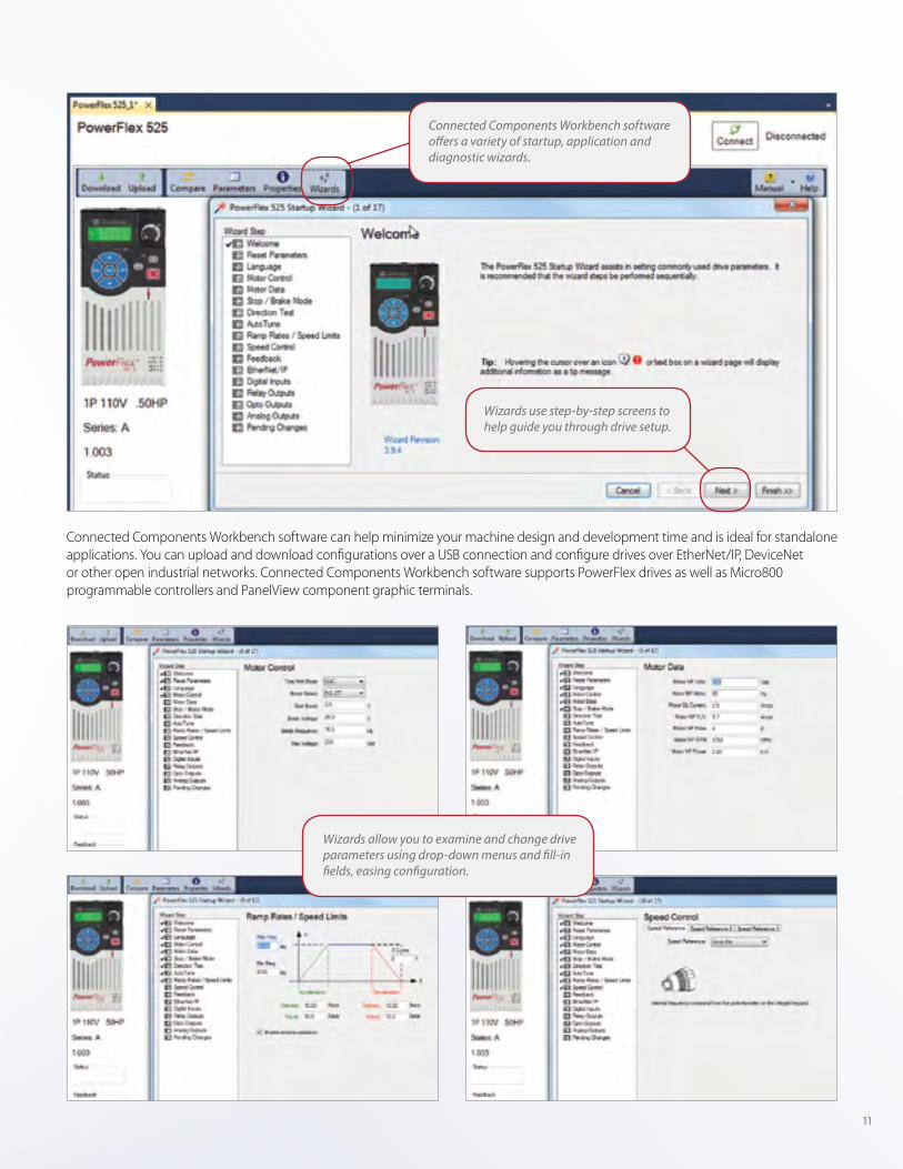
Connected Components Workbench software can help minimize your machine design and development time and is ideal for standalone applications. You can upload and download configurations over a USB connection and configure drives over EtherNet/IP, DeviceNet or other open industrial networks. Connected Components Workbench software supports PowerFlex drives as well as Micro800 programmable controllers and PanelView component graphic terminals.
Connected Components Workbench software offers a variety of startup, application and diagnostic wizards.
Wizards use step-by-step screens to help guide you through drive setup.
Wizards allow you to examine and change drive parameters using drop-down menus and fill-in fields, easing configuration.
11
CompactLogix Controller
Stratix 5700™ Switch
EtherNet/IP CONFIGURATION
IP ADDRESS
PowerFlex 525 AC Drive
If you’re searching for ways to be more efficient, consider Premier Integration. The integration of Allen-Bradley motor control devices into the Logix control platform helps reduce your programming time, ease startup and commissioning, and streamline diagnostics. By providing consolidated controller programming and device system configuration, operation and maintenance in a single software environment – Studio 5000 Logix Designer – Premier Integration helps reduce complication and errors.
Studio 5000 Logix Designer
• A single software solution using intuitive programming provides a common user experience
• Software interface streamlines device set up
• Easy access to system and machine level data as well as diagnostic information
• Configuration is centralized in Studio 5000 software for both the controllers and the drives
• Helps simplify configuration of multiple drives
• PowerFlex 520-Series AC drives use Premier Integration to help reduce development time and simplify system operation and diagnostics. The PowerFlex 527 drive enhances the user experience by utilizing the motion instruction set in the Studio 5000 Logix Designer application
Scalable, Information-enabled Programmable Automation ControllersMaximize the potential of your automation system with the exclusive experience of Premier Integration – integrating PowerFlex drives and PACs in one environment to complete your architecture. The benefits of this time-saving experience range from reduced development time to simplified maintenance. Use PowerFlex 520-Series drives with the Logix PAC® that best meets your application needs.
CompactLogix™ controllers are ideal for small to mid-size appli-cations and provide the benefits of Integrated Architecture® for lower-cost machines.
ControlLogix® systems use a common control engine with a common development environment to help achieve
high-speed, high-performance, multi-disciplined application control in an easy-to-use environment.
GuardLogix® Integrated Safety Systems provide the benefits of standard ControlLogix systems, plus safety features. When used with a GuardLogix PAC, the PowerFlex 527 AC drive offers the option of Integrated Safety via an
EtherNet/IP network to help reduce wiring, hardware and the potential for failures.
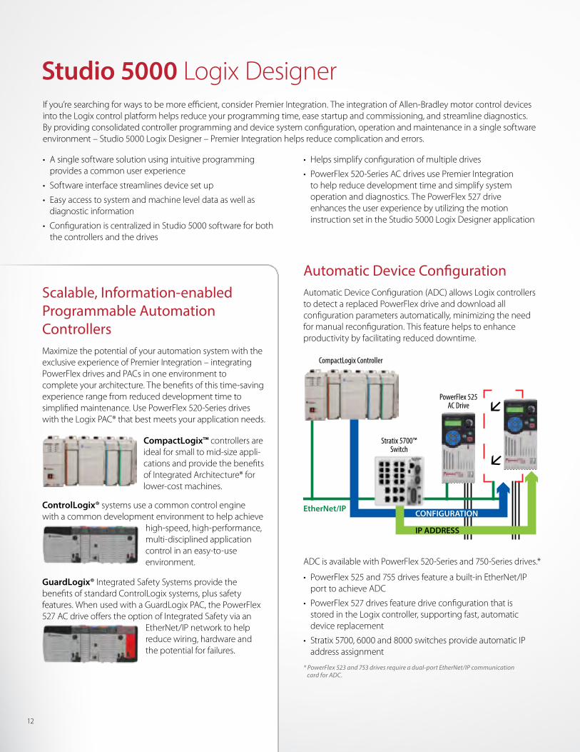
Automatic Device ConfigurationAutomatic Device Configuration (ADC) allows Logix controllers to detect a replaced PowerFlex drive and download all configuration parameters automatically, minimizing the need for manual reconfiguration. This feature helps to enhance productivity by facilitating reduced downtime.
ADC is available with PowerFlex 520-Series and 750-Series drives.*
• PowerFlex 525 and 755 drives feature a built-in EtherNet/IP port to achieve ADC
• PowerFlex 527 drives feature drive configuration that is stored in the Logix controller, supporting fast, automatic device replacement
• Stratix 5700, 6000 and 8000 switches provide automatic IP address assignment
* PowerFlex 523 and 753 drives require a dual-port EtherNet/IP communication card for ADC.
12
Drive Configuration with Studio 5000 Logix Designer
Simplify application development, use and maintenance
Studio 5000 software can help reduce programming time by automatically populating drive parameters in the controller memory as controller tags.
• Descriptive tag names are automatically generated
• Address mismatch errors can be eliminated
• Copy and paste function makes duplicating drives fast and easy
• Advanced graphical wizards walk you through drive configuration
When functioning as part of the Rockwell Automation Integrated Architecture, PowerFlex 520-Series drives can do much more than just respond to interlocking commands.
• Predict mechanical problems and help improve performance with diagnostics and real-time data
• Monitor performance either locally or remotely to make informed decisions about your assets
• Automatic Device Configuration downloads configuration parameters to a replaced drive, helping reduce downtime
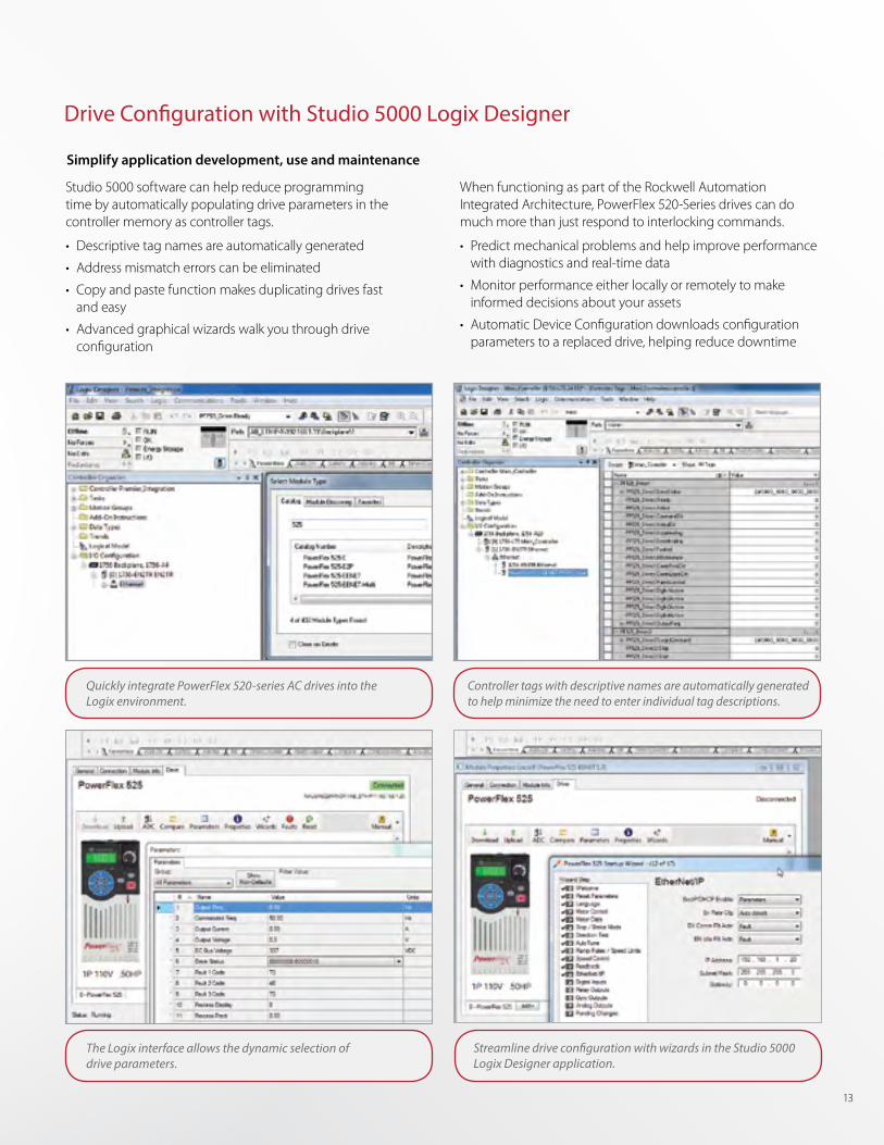
The Logix interface allows the dynamic selection of drive parameters.
Streamline drive configuration with wizards in the Studio 5000 Logix Designer application.
Quickly integrate PowerFlex 520-series AC drives into the Logix environment.
Controller tags with descriptive names are automatically generated to help minimize the need to enter individual tag descriptions.
13
Drive Programming with Studio 5000 Logix Designer Motion Instructions
When you think about it, the concept makes complete sense. A variable frequency drive that is configured and programmed like a servo drive. The benefits seem obvious. You can reduce complexity and save valuable engineering time by using a single software package with common instructions for both types of drives. And that’s just the beginning. Because the PowerFlex 527 AC drive was designed to work exclusively with Studio 5000 software and Logix Programmable Automation Controllers, the drive is able to leverage the benefits of our Logix controller capabilities and perform as a natural extension of the controller. The result is a solution that helps you achieve enhanced motor coordination.
• Machine safety is configured in the safety task of the Studio 5000 Logix Designer application. Safety connections are made on the EtherNet/IP network, and no additional wiring is required
• Synchronization – from very simple electronic gearing to electronic camming – can be accomplished using just a few instructions. This synchronization can be accomplished over the network without the need for any additional hardware devices
• Inherent automatic device replacement is a time-saving benefit of the PowerFlex 527 drive. The Logix controller maintains every aspect of the drive’s parameters, and resets them each time it connects to the drive. This creates inherent device replacement to help minimize machine downtime
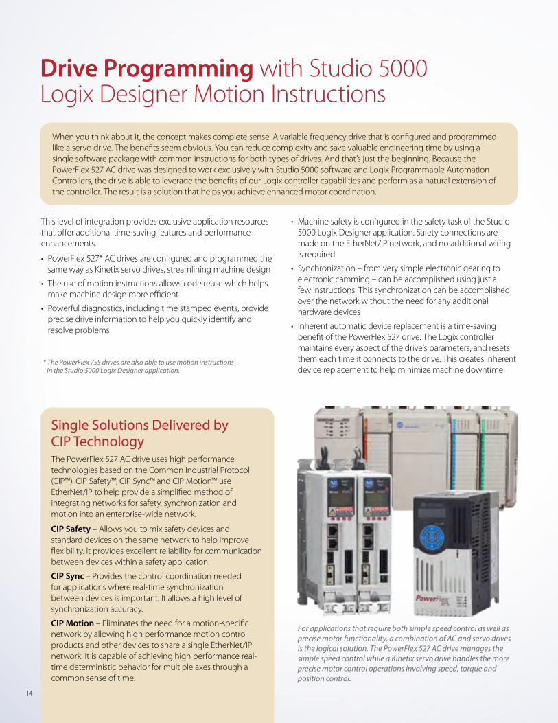
For applications that require both simple speed control as well as precise motor functionality, a combination of AC and servo drives is the logical solution. The PowerFlex 527 AC drive manages the simple speed control while a Kinetix servo drive handles the more precise motor control operations involving speed, torque and position control.
Single Solutions Delivered by CIP TechnologyThe PowerFlex 527 AC drive uses high performance technologies based on the Common Industrial Protocol (CIP™). CIP Safety™, CIP Sync™ and CIP Motion™ use EtherNet/IP to help provide a simplified method of integrating networks for safety, synchronization and motion into an enterprise-wide network.
CIP Safety – Allows you to mix safety devices and standard devices on the same network to help improve flexibility. It provides excellent reliability for communication between devices within a safety application.
CIP Sync – Provides the control coordination needed for applications where real-time synchronization between devices is important. It allows a high level of synchronization accuracy.
CIP Motion – Eliminates the need for a motion-specific network by allowing high performance motion control products and other devices to share a single EtherNet/IP network. It is capable of achieving high performance real-time deterministic behavior for multiple axes through a common sense of time.
This level of integration provides exclusive application resources that offer additional time-saving features and performance enhancements.
• PowerFlex 527* AC drives are configured and programmed the same way as Kinetix servo drives, streamlining machine design
• The use of motion instructions allows code reuse which helps make machine design more efficient
• Powerful diagnostics, including time stamped events, provide precise drive information to help you quickly identify and resolve problems
* The PowerFlex 755 drives are also able to use motion instructions in the Studio 5000 Logix Designer application.
14
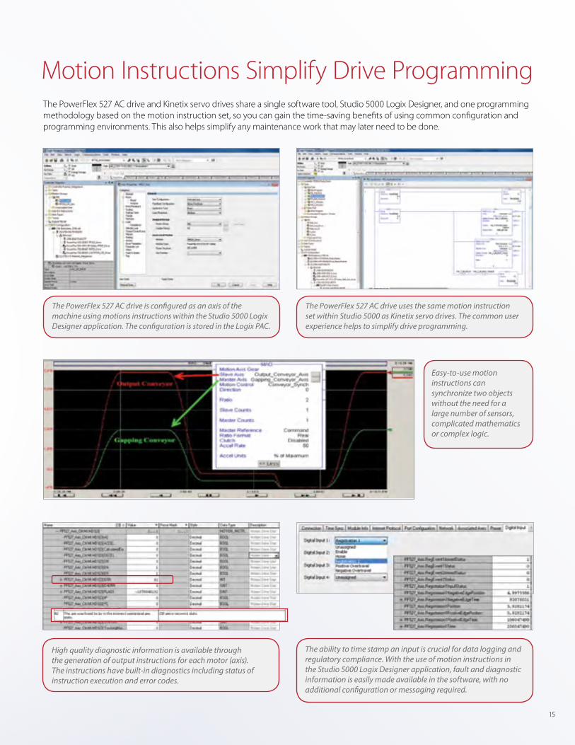
The PowerFlex 527 AC drive uses the same motion instruction set within Studio 5000 as Kinetix servo drives. The common user experience helps to simplify drive programming.
Motion Instructions Simplify Drive ProgrammingThe PowerFlex 527 AC drive and Kinetix servo drives share a single software tool, Studio 5000 Logix Designer, and one programming methodology based on the motion instruction set, so you can gain the time-saving benefits of using common configuration and programming environments. This also helps simplify any maintenance work that may later need to be done.
Easy-to-use motion instructions can synchronize two objects without the need for a large number of sensors, complicated mathematics or complex logic.
The ability to time stamp an input is crucial for data logging and regulatory compliance. With the use of motion instructions in the Studio 5000 Logix Designer application, fault and diagnostic information is easily made available in the software, with no additional configuration or messaging required.
High quality diagnostic information is available through the generation of output instructions for each motor (axis). The instructions have built-in diagnostics including status of instruction execution and error codes.
The PowerFlex 527 AC drive is configured as an axis of the machine using motions instructions within the Studio 5000 Logix Designer application. The configuration is stored in the Logix PAC.
15
POINT I/O
SensaGuard™
Stratix 5700
Motors
Guardmaster® 440R-ENETR
CompactLogix Controller
PowerFlex 525 AC drives with built-in
Safe Torque-off
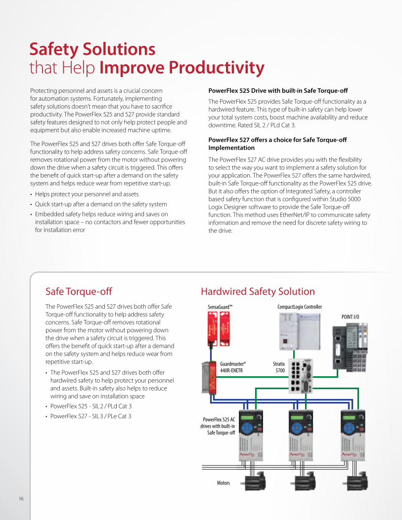
Safety Solutions that Help Improve Productivity
PowerFlex 525 Drive with built-in Safe Torque-off
The PowerFlex 525 provides Safe Torque-off functionality as a hardwired feature. This type of built-in safety can help lower your total system costs, boost machine availability and reduce downtime. Rated SIL 2 / PLd Cat 3.
PowerFlex 527 offers a choice for Safe Torque-off Implementation
The PowerFlex 527 AC drive provides you with the flexibility to select the way you want to implement a safety solution for your application. The PowerFlex 527 offers the same hardwired, built-in Safe Torque-off functionality as the PowerFlex 525 drive. But it also offers the option of Integrated Safety, a controller based safety function that is configured within Studio 5000 Logix Designer software to provide the Safe Torque-off function. This method uses EtherNet/IP to communicate safety information and remove the need for discrete safety wiring to the drive.
Protecting personnel and assets is a crucial concern for automation systems. Fortunately, implementing safety solutions doesn’t mean that you have to sacrifice productivity. The PowerFlex 525 and 527 provide standard safety features designed to not only help protect people and equipment but also enable increased machine uptime.
The PowerFlex 525 and 527 drives both offer Safe Torque-off functionality to help address safety concerns. Safe Torque-off removes rotational power from the motor without powering down the drive when a safety circuit is triggered. This offers the benefit of quick start-up after a demand on the safety system and helps reduce wear from repetitive start-up.
• Helps protect your personnel and assets
• Quick start-up after a demand on the safety system
• Embedded safety helps reduce wiring and saves on installation space – no contactors and fewer opportunities for installation error
Hardwired Safety SolutionSafe Torque-offThe PowerFlex 525 and 527 drives both offer Safe Torque-off functionality to help address safety concerns. Safe Torque-off removes rotational power from the motor without powering down the drive when a safety circuit is triggered. This offers the benefit of quick start-up after a demand on the safety system and helps reduce wear from repetitive start-up.
• The PowerFlex 525 and 527 drives both offer hardwired safety to help protect your personnel and assets. Built-in safety also helps to reduce wiring and save on installation space
• PowerFlex 525 - SIL2 / PLd Cat 3
• PowerFlex 527 - SIL3 / PLe Cat 3
16
POINT I/O with SafetySensaGuard
Motors
GuardLogix Controller
PowerFlex 527 AC drives with
Integrated Safety
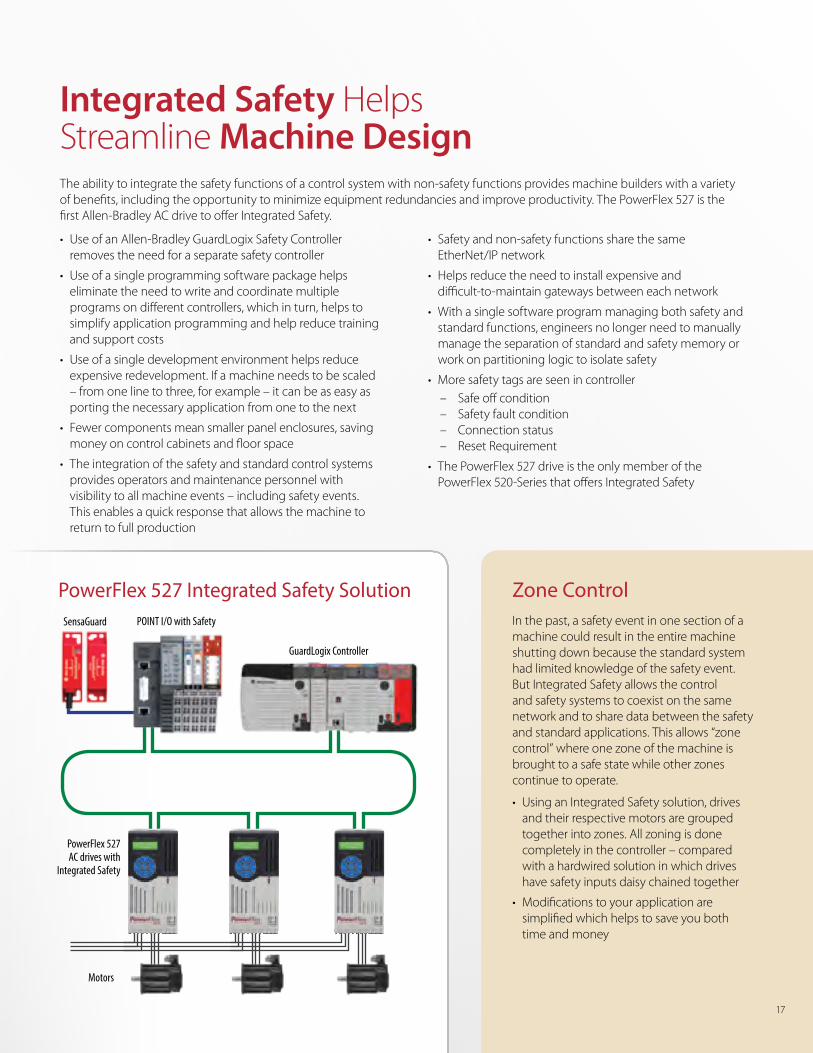
Integrated Safety Helps Streamline Machine DesignThe ability to integrate the safety functions of a control system with non-safety functions provides machine builders with a variety of benefits, including the opportunity to minimize equipment redundancies and improve productivity. The PowerFlex 527 is the first Allen-Bradley AC drive to offer Integrated Safety.
Zone ControlIn the past, a safety event in one section of a machine could result in the entire machine shutting down because the standard system had limited knowledge of the safety event. But Integrated Safety allows the control and safety systems to coexist on the same network and to share data between the safety and standard applications. This allows “zone control” where one zone of the machine is brought to a safe state while other zones continue to operate.
• Using an Integrated Safety solution, drives and their respective motors are grouped together into zones. All zoning is done completely in the controller – compared with a hardwired solution in which drives have safety inputs daisy chained together
• Modifications to your application are simplified which helps to save you both time and money
PowerFlex 527 Integrated Safety Solution
• Use of an Allen-Bradley GuardLogix Safety Controller removes the need for a separate safety controller
• Use of a single programming software package helps eliminate the need to write and coordinate multiple programs on different controllers, which in turn, helps to simplify application programming and help reduce training and support costs
• Use of a single development environment helps reduce expensive redevelopment. If a machine needs to be scaled – from one line to three, for example – it can be as easy as porting the necessary application from one to the next
• Fewer components mean smaller panel enclosures, saving money on control cabinets and floor space
• The integration of the safety and standard control systems provides operators and maintenance personnel with visibility to all machine events – including safety events. This enables a quick response that allows the machine to return to full production
• Safety and non-safety functions share the same EtherNet/IP network
• Helps reduce the need to install expensive and difficult-to-maintain gateways between each network
• With a single software program managing both safety and standard functions, engineers no longer need to manually manage the separation of standard and safety memory or work on partitioning logic to isolate safety
• More safety tags are seen in controller – Safe off condition – Safety fault condition – Connection status – Reset Requirement
• The PowerFlex 527 drive is the only member of the PowerFlex 520-Series that offers Integrated Safety
17
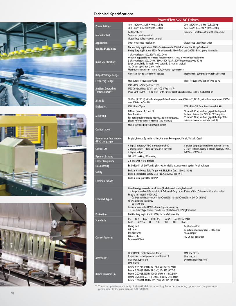
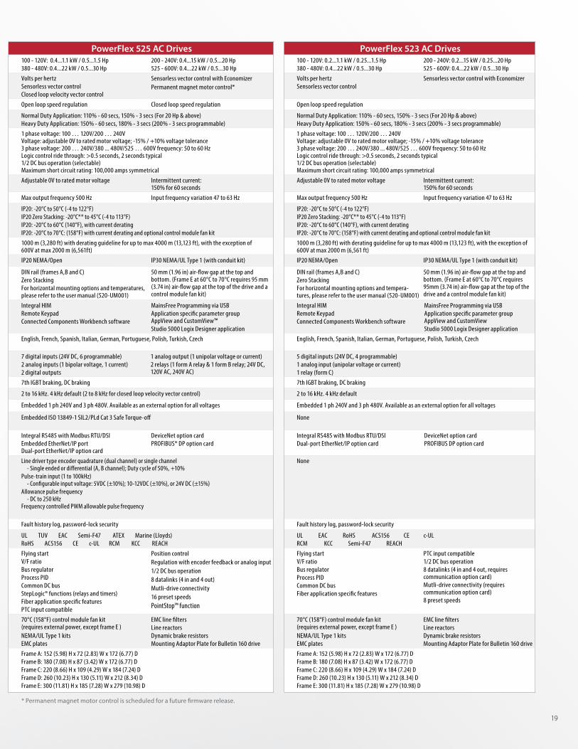
PowerFlex 527 AC Drives PowerFlex 525 AC Drives PowerFlex 523 AC Drives
Power Ratings 100 - 120V: 0.4...1.1 kW / 0.5...1.5 Hp 380 - 480V: 0.4...22 kW / 0.5...30 Hp
200 - 240V: 0.4...15 kW / 0.5...20 Hp 525 - 600V: 0.4...22 kW / 0.5...30 Hp
100 - 120V: 0.4...1.1 kW / 0.5...1.5 Hp 380 - 480V: 0.4...22 kW / 0.5...30 Hp
200 - 240V: 0.4...15 kW / 0.5...20 Hp 525 - 600V: 0.4...22 kW / 0.5...30 Hp
100 - 120V: 0.2...1.1 kW / 0.25...1.5 Hp 380 - 480V: 0.4...22 kW / 0.5...30 Hp
200 - 240V: 0.2...15 kW / 0.25...20 Hp 525 - 600V: 0.4...22 kW / 0.5...30 Hp
Motor ControlVolts per hertz Sensorless vector controlClosed loop velocity vector control
Sensorless vector control with Economizer Volts per hertz Sensorless vector controlClosed loop velocity vector control
Sensorless vector control with EconomizerPermanent magnet motor control*
Volts per hertz Sensorless vector control
Sensorless vector control with Economizer
Application Open loop speed regulation Closed loop speed regulation Open loop speed regulation Closed loop speed regulation Open loop speed regulation
Overload Capability Normal duty application: 110% for 60 seconds, 150% for 3 sec (For 20 Hp & above)Heavy duty application: 150% for 60 seconds, 180% for 3 sec (200% - 3 secs programmable)
Normal Duty Application: 110% - 60 secs, 150% - 3 secs (For 20 Hp & above)Heavy Duty Application: 150% - 60 secs, 180% - 3 secs (200% - 3 secs programmable)
Normal Duty Application: 110% - 60 secs, 150% - 3 secs (For 20 Hp & above)Heavy Duty Application: 150% - 60 secs, 180% - 3 secs (200% - 3 secs programmable)
Input Specifications
1 phase voltage: 100...120V / 200...240V Voltage: adjustable 0V to rated motor voltage; -15% / +10% voltage tolerance 3 phase voltage: 200...240V / 380...480V / 525...600V frequency: 50 to 60 Hz Logic control ride through: >0.5 seconds, 2 seconds typical 1/2 DC bus operation (selectable) Maximum short circuit rating: 100,000 amps symmetrical
1 phase voltage: 100 … 120V/200 … 240V Voltage: adjustable 0V to rated motor voltage; -15% / +10% voltage tolerance 3 phase voltage: 200 … 240V/380 ... 480V/525 … 600V frequency: 50 to 60 Hz Logic control ride through: >0.5 seconds, 2 seconds typical 1/2 DC bus operation (selectable) Maximum short circuit rating: 100,000 amps symmetrical
1 phase voltage: 100 … 120V/200 … 240V Voltage: adjustable 0V to rated motor voltage; -15% / +10% voltage tolerance 3 phase voltage: 200 … 240V/380 ... 480V/525 … 600V frequency: 50 to 60 Hz Logic control ride through: >0.5 seconds, 2 seconds typical 1/2 DC bus operation (selectable) Maximum short circuit rating: 100,000 amps symmetrical
Output Voltage Range Adjustable 0V to rated motor voltage Intermittent current: 150% for 60 seconds Adjustable 0V to rated motor voltage Intermittent current: 150% for 60 seconds
Adjustable 0V to rated motor voltage Intermittent current: 150% for 60 seconds
Frequency Range Max output frequency 590 Hz Input frequency variation 47 to 63 Hz Max output frequency 500 Hz Input frequency variation 47 to 63 Hz Max output frequency 500 Hz Input frequency variation 47 to 63 Hz
Ambient Operating Temperatures**
IP20: -20°C to 50°C (-4°F to 122°F)IP20 Zero Stacking: -20°C** to 45°C (-4°F to 113°F) IP20: -20°C to 70°C (-4°F to 158°F) with current derating and optional control module fan kit
IP20: -20°C to 50°C (-4 to 122°F)IP20 Zero Stacking: -20°C** to 45°C (-4 to 113°F)IP20: -20°C to 60°C (140°F), with current deratingIP20: -20°C to 70°C: (158°F) with current derating and optional control module fan kit
IP20: -20°C to 50°C (-4 to 122°F)IP20 Zero Stacking: -20°C** to 45°C (-4 to 113°F)IP20: -20°C to 60°C (140°F), with current deratingIP20: -20°C to 70°C: (158°F) with current derating and optional control module fan kit
Altitude 1000 m (3,280 ft) with derating guideline for up to max 4000 m (13,123 ft), with the exception of 600V at max 2000 m (6,561 ft)
1000 m (3,280 ft) with derating guideline for up to max 4000 m (13,123 ft), with the exception of 600V at max 2000 m (6,561ft)
1000 m (3,280 ft) with derating guideline for up to max 4000 m (13,123 ft), with the exception of 600V at max 2000 m (6,561 ft)
Enclosures IP20 NEMA/Open IP30 NEMA/UL Type 1 (with conduit kit) IP20 NEMA/Open IP30 NEMA/UL Type 1 (with conduit kit) IP20 NEMA/Open IP30 NEMA/UL Type 1 (with conduit kit)
Mounting
DIN rail (frames A,B and C)Zero StackingFor horizontal mounting options and temperatures, please refer to the user manual (520-UM001)
50 mm (1.96 in) air-flow gap at the top and bottom. (Frame E at 60°C to 70°C requires 95 mm (3.74 in) air-flow gap at the top of the drive and a control module fan kit)
DIN rail (frames A,B and C)Zero StackingFor horizontal mounting options and tempera-tures, please refer to the user manual (520-UM001)
50 mm (1.96 in) air-flow gap at the top and bottom. (Frame E at 60°C to 70°C requires 95mm (3.74 in) air-flow gap at the top of the drive and a control module fan kit)
Configuration
Studio 5000 Logix Designer application Integral HIM Remote KeypadConnected Components Workbench software
MainsFree Programming via USBApplication specific parameter group AppView and CustomView™Studio 5000 Logix Designer application
Integral HIMRemote KeypadConnected Components Workbench software
MainsFree Programming via USBApplication specific parameter group AppView and CustomViewStudio 5000 Logix Designer application
Human Interface Module (HIM) Languages
English, French, Spanish, Italian, German, Portuguese, Polish, Turkish, Czech English, French, Spanish, Italian, German, Portuguese, Polish, Turkish, Czech English, French, Spanish, Italian, German, Portuguese, Polish, Turkish, Czech
Control I/O4 digital inputs (24V DC, 3 programmable)2 analog inputs (1 bipolar voltage, 1 current)2 digital outputs
1 analog output (1 unipolar voltage or current)2 relays (1 form A relay & 1 form B relay; 24V DC, 120V AC, 240V AC)
7 digital inputs (24V DC, 6 programmable)2 analog inputs (1 bipolar voltage, 1 current)2 digital outputs
1 analog output (1 unipolar voltage or current)2 relays (1 form A relay & 1 form B relay; 24V DC, 120V AC, 240V AC)
5 digital inputs (24V DC, 4 programmable)1 analog input (unipolar voltage or current) 1 relay (form C)
Dynamic Braking 7th IGBT braking, DC braking 7th IGBT braking, DC braking 7th IGBT braking, DC braking
Carrier Frequency 2-8 kHz with 4 kHz default 2 to 16 kHz. 4 kHz default (2 to 8 kHz for closed loop velocity vector control) 2 to 16 kHz. 4 kHz default
EMC Filtering Embedded 1 ph 240V and 3 ph 480V. Available as an external option for all voltages Embedded 1 ph 240V and 3 ph 480V. Available as an external option for all voltages Embedded 1 ph 240V and 3 ph 480V. Available as an external option for all voltages
Safety Built-in Hardwired Safe Torque-off, SIL3, PLe, Cat 3. (ISO 13849-1)Built-in Integrated Safety SIL3, PLe, Cat 3. (ISO 13849-1)
Embedded ISO 13849-1 SIL2/PLd Cat 3 Safe Torque-off None
CommunicationsBuilt-in Dual-port EtherNet/IP Integral RS485 with Modbus RTU/DSI
Embedded EtherNet/IP port Dual-port EtherNet/IP option card
DeviceNet option cardPROFIBUS® DP option card
Integral RS485 with Modbus RTU/DSIDual-port EtherNet/IP option card
DeviceNet option cardPROFIBUS DP option card
Feedback Types
Line driver type encoder quadrature (dual channel) or single channel - Single ended or differential (A, B, Z channel) Duty cycle of 50%, +10% (Z channel with marker pulse)Pulse-train input (1 to 100k Hz) - Configurable input voltage: 5V DC (±10%); 10-12V DC (±10%), or 24V DC (±15%)Allowance pulse frequency - DC to 250 kHzFrequency controlled PWM allowable pulse frequency - Line Driver Type Encoder Quadrature (dual channel) or Single Channel
Line driver type encoder quadrature (dual channel) or single channel - Single ended or differential (A, B channel); Duty cycle of 50%, +10%Pulse-train input (1 to 100kHz) - Configurable input voltage: 5VDC (±10%); 10-12VDC (±10%), or 24V DC (±15%) Allowance pulse frequency - DC to 250 kHz Frequency controlled PWM allowable pulse frequency
None
Protection Fault history log in Studio 5000, FactoryTalk security Fault history log, password-lock security Fault history log, password-lock security
Standards UL TUV EAC Semi-F47 ATEX Marine (Lloyds)RoHS ACS156 CE c-UL RCM KCC REACH
UL TUV EAC Semi-F47 ATEX Marine (Lloyds)RoHS ACS156 CE c-UL RCM KCC REACH
UL EAC RoHS ACS156 CE c-UL RCM KCC Semi-F47 REACH
Control Features
Flying startV/F ratioBus regulatorProcess PIDCommon DC bus
Position controlRegulation with encoder feedback or analog input1/2 DC bus operation
Flying startV/F ratioBus regulatorProcess PIDCommon DC busStepLogic® functions (relays and timers)Fiber application specific featuresPTC input compatible
Position controlRegulation with encoder feedback or analog input1/2 DC bus operation8 datalinks (4 in and 4 out)Mutli-drive connectivity16 preset speedsPointStop™ function
Flying startV/F ratioBus regulatorProcess PIDCommon DC busFiber application specific features
PTC input compatible1/2 DC bus operation8 datalinks (4 in and 4 out, requires communication option card)Mutli-drive connectivity (requires communication option card)8 preset speeds
Accessories
70°C (158°F) control module fan kit (requires external power, except frame E ) NEMA/UL Type 1 kits EMC plates
EMC line filters Line reactorsDynamic brake resistors
70°C (158°F) control module fan kit (requires external power, except frame E ) NEMA/UL Type 1 kits EMC plates
EMC line filters Line reactorsDynamic brake resistorsMounting Adaptor Plate for Bulletin 160 drive
70°C (158°F) control module fan kit (requires external power, except frame E ) NEMA/UL Type 1 kits EMC plates
EMC line filters Line reactorsDynamic brake resistorsMounting Adaptor Plate for Bulletin 160 drive
Dimensions mm (in)
Frame A: 152 (5.98) H x 72 (2.83) W x 172 (6.77) D Frame B: 180 (7.08) H x 87 (3.42) W x 172 (6.77) DFrame C: 220 (8.66) H x 109 (4.29) W x 184 (7.24) D Frame D: 260 (10.23) H x 130 (5.11) W x 212 (8.34) DFrame E: 300 (11.81) H x 185 (7.28) W x 279 (10.98) D
Frame A: 152 (5.98) H x 72 (2.83) W x 172 (6.77) D Frame B: 180 (7.08) H x 87 (3.42) W x 172 (6.77) DFrame C: 220 (8.66) H x 109 (4.29) W x 184 (7.24) D Frame D: 260 (10.23) H x 130 (5.11) W x 212 (8.34) DFrame E: 300 (11.81) H x 185 (7.28) W x 279 (10.98) D
Frame A: 152 (5.98) H x 72 (2.83) W x 172 (6.77) DFrame B: 180 (7.08) H x 87 (3.42) W x 172 (6.77) D Frame C: 220 (8.66) H x 109 (4.29) W x 184 (7.24) DFrame D: 260 (10.23) H x 130 (5.11) W x 212 (8.34) DFrame E: 300 (11.81) H x 185 (7.28) W x 279 (10.98) D
** These temperatures are for typical vertical drive mounting. For other mounting options and temperatures, please refer to the user manual (520-UM001).
Technical Specifications
18
PowerFlex 527 AC Drives PowerFlex 525 AC Drives PowerFlex 523 AC Drives
Power Ratings 100 - 120V: 0.4...1.1 kW / 0.5...1.5 Hp 380 - 480V: 0.4...22 kW / 0.5...30 Hp
200 - 240V: 0.4...15 kW / 0.5...20 Hp 525 - 600V: 0.4...22 kW / 0.5...30 Hp
100 - 120V: 0.4...1.1 kW / 0.5...1.5 Hp 380 - 480V: 0.4...22 kW / 0.5...30 Hp
200 - 240V: 0.4...15 kW / 0.5...20 Hp 525 - 600V: 0.4...22 kW / 0.5...30 Hp
100 - 120V: 0.2...1.1 kW / 0.25...1.5 Hp 380 - 480V: 0.4...22 kW / 0.5...30 Hp
200 - 240V: 0.2...15 kW / 0.25...20 Hp 525 - 600V: 0.4...22 kW / 0.5...30 Hp
Motor ControlVolts per hertz Sensorless vector controlClosed loop velocity vector control
Sensorless vector control with Economizer Volts per hertz Sensorless vector controlClosed loop velocity vector control
Sensorless vector control with EconomizerPermanent magnet motor control*
Volts per hertz Sensorless vector control
Sensorless vector control with Economizer
Application Open loop speed regulation Closed loop speed regulation Open loop speed regulation Closed loop speed regulation Open loop speed regulation
Overload Capability Normal duty application: 110% for 60 seconds, 150% for 3 sec (For 20 Hp & above)Heavy duty application: 150% for 60 seconds, 180% for 3 sec (200% - 3 secs programmable)
Normal Duty Application: 110% - 60 secs, 150% - 3 secs (For 20 Hp & above)Heavy Duty Application: 150% - 60 secs, 180% - 3 secs (200% - 3 secs programmable)
Normal Duty Application: 110% - 60 secs, 150% - 3 secs (For 20 Hp & above)Heavy Duty Application: 150% - 60 secs, 180% - 3 secs (200% - 3 secs programmable)
Input Specifications
1 phase voltage: 100...120V / 200...240V Voltage: adjustable 0V to rated motor voltage; -15% / +10% voltage tolerance 3 phase voltage: 200...240V / 380...480V / 525...600V frequency: 50 to 60 Hz Logic control ride through: >0.5 seconds, 2 seconds typical 1/2 DC bus operation (selectable) Maximum short circuit rating: 100,000 amps symmetrical
1 phase voltage: 100 … 120V/200 … 240V Voltage: adjustable 0V to rated motor voltage; -15% / +10% voltage tolerance 3 phase voltage: 200 … 240V/380 ... 480V/525 … 600V frequency: 50 to 60 Hz Logic control ride through: >0.5 seconds, 2 seconds typical 1/2 DC bus operation (selectable) Maximum short circuit rating: 100,000 amps symmetrical
1 phase voltage: 100 … 120V/200 … 240V Voltage: adjustable 0V to rated motor voltage; -15% / +10% voltage tolerance 3 phase voltage: 200 … 240V/380 ... 480V/525 … 600V frequency: 50 to 60 Hz Logic control ride through: >0.5 seconds, 2 seconds typical 1/2 DC bus operation (selectable) Maximum short circuit rating: 100,000 amps symmetrical
Output Voltage Range Adjustable 0V to rated motor voltage Intermittent current: 150% for 60 seconds Adjustable 0V to rated motor voltage Intermittent current: 150% for 60 seconds
Adjustable 0V to rated motor voltage Intermittent current: 150% for 60 seconds
Frequency Range Max output frequency 590 Hz Input frequency variation 47 to 63 Hz Max output frequency 500 Hz Input frequency variation 47 to 63 Hz Max output frequency 500 Hz Input frequency variation 47 to 63 Hz
Ambient Operating Temperatures**
IP20: -20°C to 50°C (-4°F to 122°F)IP20 Zero Stacking: -20°C** to 45°C (-4°F to 113°F) IP20: -20°C to 70°C (-4°F to 158°F) with current derating and optional control module fan kit
IP20: -20°C to 50°C (-4 to 122°F)IP20 Zero Stacking: -20°C** to 45°C (-4 to 113°F)IP20: -20°C to 60°C (140°F), with current deratingIP20: -20°C to 70°C: (158°F) with current derating and optional control module fan kit
IP20: -20°C to 50°C (-4 to 122°F)IP20 Zero Stacking: -20°C** to 45°C (-4 to 113°F)IP20: -20°C to 60°C (140°F), with current deratingIP20: -20°C to 70°C: (158°F) with current derating and optional control module fan kit
Altitude 1000 m (3,280 ft) with derating guideline for up to max 4000 m (13,123 ft), with the exception of 600V at max 2000 m (6,561 ft)
1000 m (3,280 ft) with derating guideline for up to max 4000 m (13,123 ft), with the exception of 600V at max 2000 m (6,561ft)
1000 m (3,280 ft) with derating guideline for up to max 4000 m (13,123 ft), with the exception of 600V at max 2000 m (6,561 ft)
Enclosures IP20 NEMA/Open IP30 NEMA/UL Type 1 (with conduit kit) IP20 NEMA/Open IP30 NEMA/UL Type 1 (with conduit kit) IP20 NEMA/Open IP30 NEMA/UL Type 1 (with conduit kit)
Mounting
DIN rail (frames A,B and C)Zero StackingFor horizontal mounting options and temperatures, please refer to the user manual (520-UM001)
50 mm (1.96 in) air-flow gap at the top and bottom. (Frame E at 60°C to 70°C requires 95 mm (3.74 in) air-flow gap at the top of the drive and a control module fan kit)
DIN rail (frames A,B and C)Zero StackingFor horizontal mounting options and temperatures, please refer to the user manual (520-UM001)
50 mm (1.96 in) air-flow gap at the top and bottom. (Frame E at 60°C to 70°C requires 95 mm (3.74 in) air-flow gap at the top of the drive and a control module fan kit)
DIN rail (frames A,B and C)Zero StackingFor horizontal mounting options and tempera-tures, please refer to the user manual (520-UM001)
50 mm (1.96 in) air-flow gap at the top and bottom. (Frame E at 60°C to 70°C requires 95mm (3.74 in) air-flow gap at the top of the drive and a control module fan kit)
Configuration
Studio 5000 Logix Designer application Integral HIM Remote KeypadConnected Components Workbench software
MainsFree Programming via USBApplication specific parameter group AppView and CustomView™Studio 5000 Logix Designer application
Integral HIMRemote KeypadConnected Components Workbench software
MainsFree Programming via USBApplication specific parameter group AppView and CustomViewStudio 5000 Logix Designer application
Human Interface Module (HIM) Languages
English, French, Spanish, Italian, German, Portuguese, Polish, Turkish, Czech English, French, Spanish, Italian, German, Portuguese, Polish, Turkish, Czech English, French, Spanish, Italian, German, Portuguese, Polish, Turkish, Czech
Control I/O4 digital inputs (24V DC, 3 programmable)2 analog inputs (1 bipolar voltage, 1 current)2 digital outputs
1 analog output (1 unipolar voltage or current)2 relays (1 form A relay & 1 form B relay; 24V DC, 120V AC, 240V AC)
7 digital inputs (24V DC, 6 programmable)2 analog inputs (1 bipolar voltage, 1 current)2 digital outputs
1 analog output (1 unipolar voltage or current)2 relays (1 form A relay & 1 form B relay; 24V DC, 120V AC, 240V AC)
5 digital inputs (24V DC, 4 programmable)1 analog input (unipolar voltage or current) 1 relay (form C)
Dynamic Braking 7th IGBT braking, DC braking 7th IGBT braking, DC braking 7th IGBT braking, DC braking
Carrier Frequency 2-8 kHz with 4 kHz default 2 to 16 kHz. 4 kHz default (2 to 8 kHz for closed loop velocity vector control) 2 to 16 kHz. 4 kHz default
EMC Filtering Embedded 1 ph 240V and 3 ph 480V. Available as an external option for all voltages Embedded 1 ph 240V and 3 ph 480V. Available as an external option for all voltages Embedded 1 ph 240V and 3 ph 480V. Available as an external option for all voltages
Safety Built-in Hardwired Safe Torque-off, SIL3, PLe, Cat 3. (ISO 13849-1)Built-in Integrated Safety SIL3, PLe, Cat 3. (ISO 13849-1)
Embedded ISO 13849-1 SIL2/PLd Cat 3 Safe Torque-off None
CommunicationsBuilt-in Dual-port EtherNet/IP Integral RS485 with Modbus RTU/DSI
Embedded EtherNet/IP port Dual-port EtherNet/IP option card
DeviceNet option cardPROFIBUS® DP option card
Integral RS485 with Modbus RTU/DSIDual-port EtherNet/IP option card
DeviceNet option cardPROFIBUS DP option card
Feedback Types
Line driver type encoder quadrature (dual channel) or single channel - Single ended or differential (A, B, Z channel) Duty cycle of 50%, +10% (Z channel with marker pulse)Pulse-train input (1 to 100k Hz) - Configurable input voltage: 5V DC (±10%); 10-12V DC (±10%), or 24V DC (±15%)Allowance pulse frequency - DC to 250 kHzFrequency controlled PWM allowable pulse frequency - Line Driver Type Encoder Quadrature (dual channel) or Single Channel
Line driver type encoder quadrature (dual channel) or single channel - Single ended or differential (A, B channel); Duty cycle of 50%, +10%Pulse-train input (1 to 100kHz) - Configurable input voltage: 5VDC (±10%); 10-12VDC (±10%), or 24V DC (±15%) Allowance pulse frequency - DC to 250 kHz Frequency controlled PWM allowable pulse frequency
None
Protection Fault history log in Studio 5000, FactoryTalk security Fault history log, password-lock security Fault history log, password-lock security
Standards UL TUV EAC Semi-F47 ATEX Marine (Lloyds)RoHS ACS156 CE c-UL RCM KCC REACH
UL TUV EAC Semi-F47 ATEX Marine (Lloyds)RoHS ACS156 CE c-UL RCM KCC REACH
UL EAC RoHS ACS156 CE c-UL RCM KCC Semi-F47 REACH
Control Features
Flying startV/F ratioBus regulatorProcess PIDCommon DC bus
Position controlRegulation with encoder feedback or analog input1/2 DC bus operation
Flying startV/F ratioBus regulatorProcess PIDCommon DC busStepLogic® functions (relays and timers)Fiber application specific featuresPTC input compatible
Position controlRegulation with encoder feedback or analog input1/2 DC bus operation8 datalinks (4 in and 4 out)Mutli-drive connectivity16 preset speedsPointStop™ function
Flying startV/F ratioBus regulatorProcess PIDCommon DC busFiber application specific features
PTC input compatible1/2 DC bus operation8 datalinks (4 in and 4 out, requires communication option card)Mutli-drive connectivity (requires communication option card)8 preset speeds
Accessories
70°C (158°F) control module fan kit (requires external power, except frame E ) NEMA/UL Type 1 kits EMC plates
EMC line filters Line reactorsDynamic brake resistors
70°C (158°F) control module fan kit (requires external power, except frame E ) NEMA/UL Type 1 kits EMC plates
EMC line filters Line reactorsDynamic brake resistorsMounting Adaptor Plate for Bulletin 160 drive
70°C (158°F) control module fan kit (requires external power, except frame E ) NEMA/UL Type 1 kits EMC plates
EMC line filters Line reactorsDynamic brake resistorsMounting Adaptor Plate for Bulletin 160 drive
Dimensions mm (in)
Frame A: 152 (5.98) H x 72 (2.83) W x 172 (6.77) D Frame B: 180 (7.08) H x 87 (3.42) W x 172 (6.77) DFrame C: 220 (8.66) H x 109 (4.29) W x 184 (7.24) D Frame D: 260 (10.23) H x 130 (5.11) W x 212 (8.34) DFrame E: 300 (11.81) H x 185 (7.28) W x 279 (10.98) D
Frame A: 152 (5.98) H x 72 (2.83) W x 172 (6.77) D Frame B: 180 (7.08) H x 87 (3.42) W x 172 (6.77) DFrame C: 220 (8.66) H x 109 (4.29) W x 184 (7.24) D Frame D: 260 (10.23) H x 130 (5.11) W x 212 (8.34) DFrame E: 300 (11.81) H x 185 (7.28) W x 279 (10.98) D
Frame A: 152 (5.98) H x 72 (2.83) W x 172 (6.77) DFrame B: 180 (7.08) H x 87 (3.42) W x 172 (6.77) D Frame C: 220 (8.66) H x 109 (4.29) W x 184 (7.24) DFrame D: 260 (10.23) H x 130 (5.11) W x 212 (8.34) DFrame E: 300 (11.81) H x 185 (7.28) W x 279 (10.98) D
* Permanent magnet motor control is scheduled for a future firmware release.
19
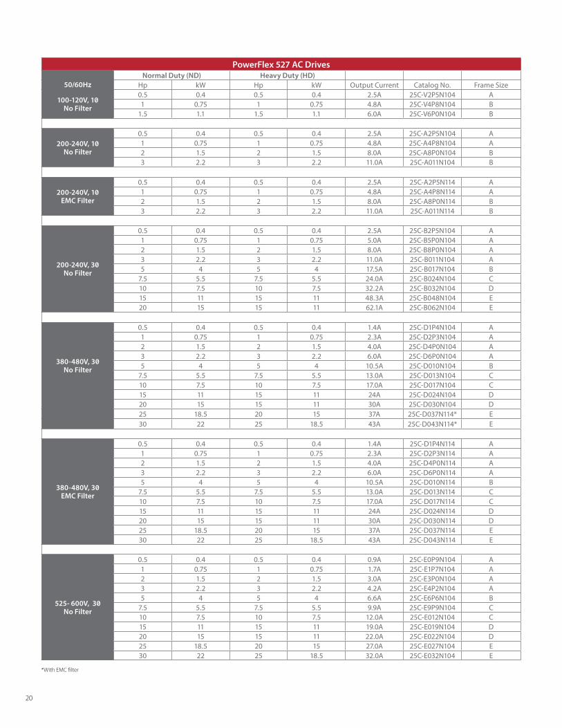
PowerFlex 527 AC Drives Normal Duty (ND) Heavy Duty (HD)
50/60Hz Hp kW Hp kW Output Current Catalog No. Frame Size
100-120V, 1 No Filter
0.5 0.4 0.5 0.4 2.5A 25C-V2P5N104 A1 0.75 1 0.75 4.8A 25C-V4P8N104 B
1.5 1.1 1.5 1.1 6.0A 25C-V6P0N104 B
200-240V, 1 No Filter
0.5 0.4 0.5 0.4 2.5A 25C-A2P5N104 A1 0.75 1 0.75 4.8A 25C-A4P8N104 A2 1.5 2 1.5 8.0A 25C-A8P0N104 B3 2.2 3 2.2 11.0A 25C-A011N104 B
200-240V, 1 EMC Filter
0.5 0.4 0.5 0.4 2.5A 25C-A2P5N114 A1 0.75 1 0.75 4.8A 25C-A4P8N114 A2 1.5 2 1.5 8.0A 25C-A8P0N114 B3 2.2 3 2.2 11.0A 25C-A011N114 B
200-240V, 3 No Filter
0.5 0.4 0.5 0.4 2.5A 25C-B2P5N104 A1 0.75 1 0.75 5.0A 25C-B5P0N104 A2 1.5 2 1.5 8.0A 25C-B8P0N104 A3 2.2 3 2.2 11.0A 25C-B011N104 A5 4 5 4 17.5A 25C-B017N104 B
7.5 5.5 7.5 5.5 24.0A 25C-B024N104 C10 7.5 10 7.5 32.2A 25C-B032N104 D15 11 15 11 48.3A 25C-B048N104 E20 15 15 11 62.1A 25C-B062N104 E
380-480V, 3 No Filter
0.5 0.4 0.5 0.4 1.4A 25C-D1P4N104 A1 0.75 1 0.75 2.3A 25C-D2P3N104 A2 1.5 2 1.5 4.0A 25C-D4P0N104 A3 2.2 3 2.2 6.0A 25C-D6P0N104 A5 4 5 4 10.5A 25C-D010N104 B
7.5 5.5 7.5 5.5 13.0A 25C-D013N104 C10 7.5 10 7.5 17.0A 25C-D017N104 C15 11 15 11 24A 25C-D024N104 D20 15 15 11 30A 25C-D030N104 D25 18.5 20 15 37A 25C-D037N114* E30 22 25 18.5 43A 25C-D043N114* E
380-480V, 3 EMC Filter
0.5 0.4 0.5 0.4 1.4A 25C-D1P4N114 A1 0.75 1 0.75 2.3A 25C-D2P3N114 A2 1.5 2 1.5 4.0A 25C-D4P0N114 A3 2.2 3 2.2 6.0A 25C-D6P0N114 A5 4 5 4 10.5A 25C-D010N114 B
7.5 5.5 7.5 5.5 13.0A 25C-D013N114 C10 7.5 10 7.5 17.0A 25C-D017N114 C15 11 15 11 24A 25C-D024N114 D20 15 15 11 30A 25C-D030N114 D25 18.5 20 15 37A 25C-D037N114 E30 22 25 18.5 43A 25C-D043N114 E
525- 600V, 3 No Filter
0.5 0.4 0.5 0.4 0.9A 25C-E0P9N104 A1 0.75 1 0.75 1.7A 25C-E1P7N104 A2 1.5 2 1.5 3.0A 25C-E3P0N104 A3 2.2 3 2.2 4.2A 25C-E4P2N104 A5 4 5 4 6.6A 25C-E6P6N104 B
7.5 5.5 7.5 5.5 9.9A 25C-E9P9N104 C10 7.5 10 7.5 12.0A 25C-E012N104 C15 11 15 11 19.0A 25C-E019N104 D20 15 15 11 22.0A 25C-E022N104 D25 18.5 20 15 27.0A 25C-E027N104 E30 22 25 18.5 32.0A 25C-E032N104 E
*With EMC filter
20

PowerFlex 525 AC Drives Normal Duty (ND) Heavy Duty (HD)
50/60Hz Hp kW Hp kW Output Current Catalog No. Frame Size
100-120V, 1 No Filter
0.5 0.4 0.5 0.4 2.5A 25B-V2P5N104 A1 0.75 1 0.75 4.8A 25B-V4P8N104 B
1.5 1.1 1.5 1.1 6.0A 25B-V6P0N104 B
200-240V, 1 No Filter
0.5 0.4 0.5 0.4 2.5A 25B-A2P5N104 A1 0.75 1 0.75 4.8A 25B-A4P8N104 A2 1.5 2 1.5 8.0A 25B-A8P0N104 B3 2.2 3 2.2 11.0A 25B-A011N104 B
200-240V, 1 EMC Filter
0.5 0.4 0.5 0.4 2.5A 25B-A2P5N114 A1 0.75 1 0.75 4.8A 25B-A4P8N114 A2 1.5 2 1.5 8.0A 25B-A8P0N114 B3 2.2 3 2.2 11.0A 25B-A011N114 B
200-240V, 3 No Filter
0.5 0.4 0.5 0.4 2.5A 25B-B2P5N104 A1 0.75 1 0.75 5.0A 25B-B5P0N104 A2 1.5 2 1.5 8.0A 25B-B8P0N104 A3 2.2 3 2.2 11.0A 25B-B011N104 A5 4 5 4 17.5A 25B-B017N104 B
7.5 5.5 7.5 5.5 24.0A 25B-B024N104 C10 7.5 10 7.5 32.2A 25B-B032N104 D15 11 15 11 48.3A 25B-B048N104 E20 15 15 11 62.1A 25B-B062N104 E
380-480V, 3 No Filter
0.5 0.4 0.5 0.4 1.4A 25B-D1P4N104 A1 0.75 1 0.75 2.3A 25B-D2P3N104 A2 1.5 2 1.5 4.0A 25B-D4P0N104 A3 2.2 3 2.2 6.0A 25B-D6P0N104 A5 4 5 4 10.5A 25B-D010N104 B
7.5 5.5 7.5 5.5 13.0A 25B-D013N104 C10 7.5 10 7.5 17.0A 25B-D017N104 C15 11 15 11 24A 25B-D024N104 D20 15 15 11 30A 25B-D030N104 D25 18.5 20 15 37A 25B-D037N114* E30 22 25 18.5 43A 25B-D043N114* E
380-480V, 3 EMC Filter
0.5 0.4 0.5 0.4 1.4A 25B-D1P4N114 A1 0.75 1 0.75 2.3A 25B-D2P3N114 A2 1.5 2 1.5 4.0A 25B-D4P0N114 A3 2.2 3 2.2 6.0A 25B-D6P0N114 A5 4 5 4 10.5A 25B-D010N114 B
7.5 5.5 7.5 5.5 13.0A 25B-D013N114 C10 7.5 10 7.5 17.0A 25B-D017N114 C15 11 15 11 24A 25B-D024N114 D20 15 15 11 30A 25B-D030N114 D25 18.5 20 15 37A 25B-D037N114 E30 22 25 18.5 43A 25B-D043N114 E
525- 600V, 3 No Filter
0.5 0.4 0.5 0.4 0.9A 25B-E0P9N104 A1 0.75 1 0.75 1.7A 25B-E1P7N104 A2 1.5 2 1.5 3.0A 25B-E3P0N104 A3 2.2 3 2.2 4.2A 25B-E4P2N104 A5 4 5 4 6.6A 25B-E6P6N104 B
7.5 5.5 7.5 5.5 9.9A 25B-E9P9N104 C10 7.5 10 7.5 12.0A 25B-E012N104 C15 11 15 11 19.0A 25B-E019N104 D20 15 15 11 22.0A 25B-E022N104 D25 18.5 20 15 27.0A 25B-E027N104 E30 22 25 18.5 32.0A 25B-E032N104 E
*With EMC filter
21
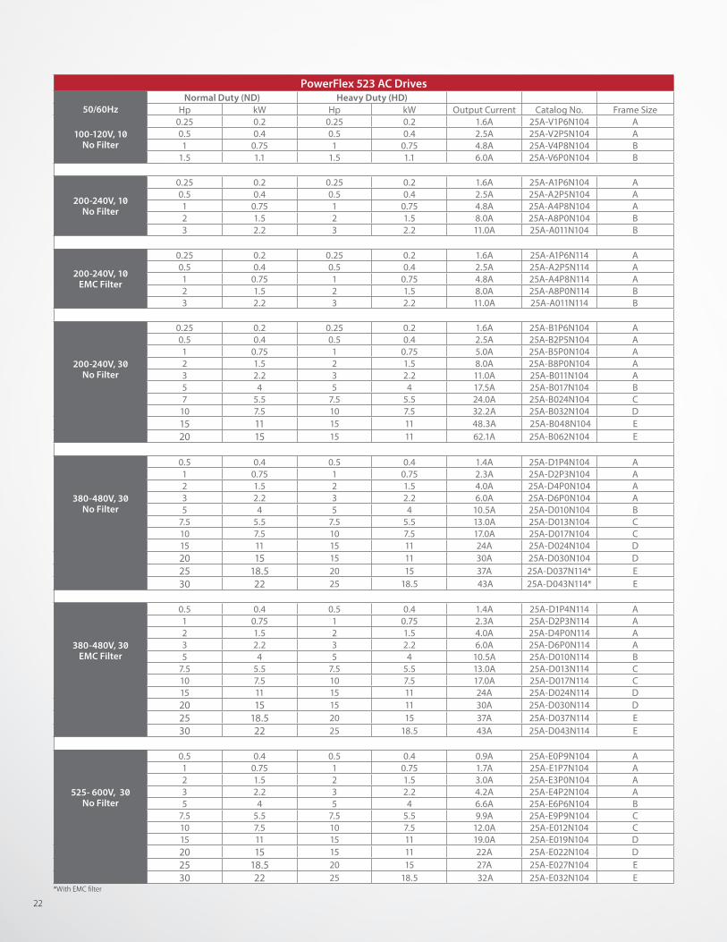
PowerFlex 523 AC Drives Normal Duty (ND) Heavy Duty (HD)
50/60Hz Hp kW Hp kW Output Current Catalog No. Frame Size
100-120V, 1 No Filter
0.25 0.2 0.25 0.2 1.6A 25A-V1P6N104 A0.5 0.4 0.5 0.4 2.5A 25A-V2P5N104 A1 0.75 1 0.75 4.8A 25A-V4P8N104 B
1.5 1.1 1.5 1.1 6.0A 25A-V6P0N104 B
200-240V, 1 No Filter
0.25 0.2 0.25 0.2 1.6A 25A-A1P6N104 A0.5 0.4 0.5 0.4 2.5A 25A-A2P5N104 A1 0.75 1 0.75 4.8A 25A-A4P8N104 A2 1.5 2 1.5 8.0A 25A-A8P0N104 B3 2.2 3 2.2 11.0A 25A-A011N104 B
200-240V, 1 EMC Filter
0.25 0.2 0.25 0.2 1.6A 25A-A1P6N114 A0.5 0.4 0.5 0.4 2.5A 25A-A2P5N114 A1 0.75 1 0.75 4.8A 25A-A4P8N114 A2 1.5 2 1.5 8.0A 25A-A8P0N114 B3 2.2 3 2.2 11.0A 25A-A011N114 B
200-240V, 3 No Filter
0.25 0.2 0.25 0.2 1.6A 25A-B1P6N104 A0.5 0.4 0.5 0.4 2.5A 25A-B2P5N104 A1 0.75 1 0.75 5.0A 25A-B5P0N104 A2 1.5 2 1.5 8.0A 25A-B8P0N104 A3 2.2 3 2.2 11.0A 25A-B011N104 A5 4 5 4 17.5A 25A-B017N104 B7 5.5 7.5 5.5 24.0A 25A-B024N104 C
10 7.5 10 7.5 32.2A 25A-B032N104 D15 11 15 11 48.3A 25A-B048N104 E 20 15 15 11 62.1A 25A-B062N104 E
380-480V, 3 No Filter
0.5 0.4 0.5 0.4 1.4A 25A-D1P4N104 A1 0.75 1 0.75 2.3A 25A-D2P3N104 A2 1.5 2 1.5 4.0A 25A-D4P0N104 A3 2.2 3 2.2 6.0A 25A-D6P0N104 A5 4 5 4 10.5A 25A-D010N104 B
7.5 5.5 7.5 5.5 13.0A 25A-D013N104 C10 7.5 10 7.5 17.0A 25A-D017N104 C15 11 15 11 24A 25A-D024N104 D20 15 15 11 30A 25A-D030N104 D25 18.5 20 15 37A 25A-D037N114* E30 22 25 18.5 43A 25A-D043N114* E
380-480V, 3 EMC Filter
0.5 0.4 0.5 0.4 1.4A 25A-D1P4N114 A1 0.75 1 0.75 2.3A 25A-D2P3N114 A2 1.5 2 1.5 4.0A 25A-D4P0N114 A3 2.2 3 2.2 6.0A 25A-D6P0N114 A5 4 5 4 10.5A 25A-D010N114 B
7.5 5.5 7.5 5.5 13.0A 25A-D013N114 C10 7.5 10 7.5 17.0A 25A-D017N114 C15 11 15 11 24A 25A-D024N114 D20 15 15 11 30A 25A-D030N114 D25 18.5 20 15 37A 25A-D037N114 E30 22 25 18.5 43A 25A-D043N114 E
525- 600V, 3 No Filter
0.5 0.4 0.5 0.4 0.9A 25A-E0P9N104 A1 0.75 1 0.75 1.7A 25A-E1P7N104 A2 1.5 2 1.5 3.0A 25A-E3P0N104 A3 2.2 3 2.2 4.2A 25A-E4P2N104 A5 4 5 4 6.6A 25A-E6P6N104 B
7.5 5.5 7.5 5.5 9.9A 25A-E9P9N104 C10 7.5 10 7.5 12.0A 25A-E012N104 C15 11 15 11 19.0A 25A-E019N104 D20 15 15 11 22A 25A-E022N104 D25 18.5 20 15 27A 25A-E027N104 E30 22 25 18.5 32A 25A-E032N104 E
*With EMC filter
22
ControlPowerFlex 523 AC Drive• Volts per Hertz• Sensorless Vector Control
PowerFlex 525 AC Drive• Volts per Hertz • Sensorless Vector Control • Closed Loop Velocity Vector Control• Permanent Magnet Motor Control*
PowerFlex 527 AC Drive• Volts per Hertz • Sensorless Vector Control • Closed Loop Velocity Vector Control
Position ControlPowerFlex 525 AC Drive• PointStop positioning control stops motor load in a
consistent position without encoder feedback• Closed loop feedback with an optional encoder card• Point-to-point positioning mode
Communications• Built-in EtherNet/IP for PowerFlex 525 and 527 AC drives
PowerFlex 523 and 525 AC Drive• Embedded DSI port• Dual-port EtherNet/IP option card• DeviceNet and PROFIBUS option cards
Energy Savings• Economizer mode in SVC adjusts current output to help
reduce energy costs• Energy data monitoring and reporting capability• Permanent magnet motor control* for PowerFlex 525 and
527 AC drives
Hardware• Modular design with removable control modules• Same control module for the entire power range• Addition of option cards does not affect footprint of the drive• Vertical, side-by-side mounting to reduce panel space• Flexible, time-saving installation using DIN rail mounting with
A, B and C frame drives• Horizontal mounting with a control module fan kit• Ambient operating temperatures from -20°C (-4°F) up to 70°C
(158°F) with current derating and a control module fan kit• IP20 NEMA/Open, IP30 NEMA/UL Type 1 (with conduit kit)• EMC filtering embedded at 200V and 400V; optional EMC
filtering available for all voltages• Conformal coating to IEC 60721 3C2 standards over the
circuitry helps improve the drives’ robustness (chemicals and gasses only)
Programming and CommissioningPowerFlex 523 and 525 AC Drives• HIM supports multiple languages and features QuickView
scrolling text• Application specific parameter groups and customized
application settings using AppView and CustomView tools• Simplified configuration and MainsFree programming using
standard USB cables• Connected Components Workbench software for fast and
easy drive configuration• Premier Integration with the Logix control platform with the
Studio 5000 Logix Designer application
PowerFlex 527 AC Drive• Premier Integration with the Logix control platform with the
Studio 5000 Logix Designer application• Shares motion instructions in Studio 5000 Logix Designer with
Kinetix servo drives to help simplify machine development• Configure, program and reuse application profiles to help
reduce engineering time and effort
PowerFlex 520-Series AC Drives Maximize System Performance
Tools and ResourcesA variety of tools and resources are available to help you select Allen-Bradley products and design application solutions using those products. Drives and Motion Accelerator Toolkit uses a System Development Wizard to take system data entered by the designer and automatically generate files such as a custom bill of material, CAD drawings and logic code for the specific drive and PAC used in the application.Integrated Architecture Builder provides an efficient way to design systems leveraging the Rockwell Automation Integrated Architecture Refer to www.ab.com/go/iatools for additional resources and downloads.
Motion Analyzer software helps machine builders by making it faster and easier to analyze, optimize, and select motion and drive control systems. A cloud-based architecture and a wide range of tools and features help users find the right set of products for their application.
Energy Savings Calculators demonstrate how installing a PowerFlex drive for your fan or pump can help reduce energy costs when compared with traditional flow control methods. Download the tools at: http://www.rockwellenergycalc.com/
* Permanent magnet motor control is scheduled for a future firmware release.
23
Rockwell Automation, Inc. (NYSE:ROK), the world’s largest company dedicated to industrial automation, makes its customers more productive and the world more sustainable. Throughout the world, our flagship Allen-Bradley and Rockwell Software® product brands are recognized for innovation and excellence.
Publication 520-BR001D-EN-P - June 2015 Copyright © 2015 Rockwell Automation, Inc. All Rights Reserved. Printed in USA.Supersedes Publication 520-BR001C-EN-P - March 2015
Allen-Bradley, AppView, ArmorBlock, CompactLogix, Connected Components Workbench, ControlLogix, CustomView, GuardLogix, Guardmaster, Integrated Architecture, Kinetix, LISTEN. THINK. SOLVE, Logix PAC, MainsFree, Micro800, PanelView, PointStop, PowerFlex, QuickView, Rockwell Software, SensaGuard, StepLogic, Stratix 5700, Studio 5000, Studio 5000 Logix Designer are trademarks of Rockwell Automation, Inc. CIP, CIP Motion, CIP Safety, CIP Sync, DeviceNet and EtherNet/IP are trademarks of the ODVA. Microsoft and Visual Studio are trademarks of Microsoft Corporation. PROFIBUS is a trademark of PROFIBUS & PROFINET International. Trademarks not belonging to Rockwell Automation are property of their respective companies.
www.rockwellautomation.com
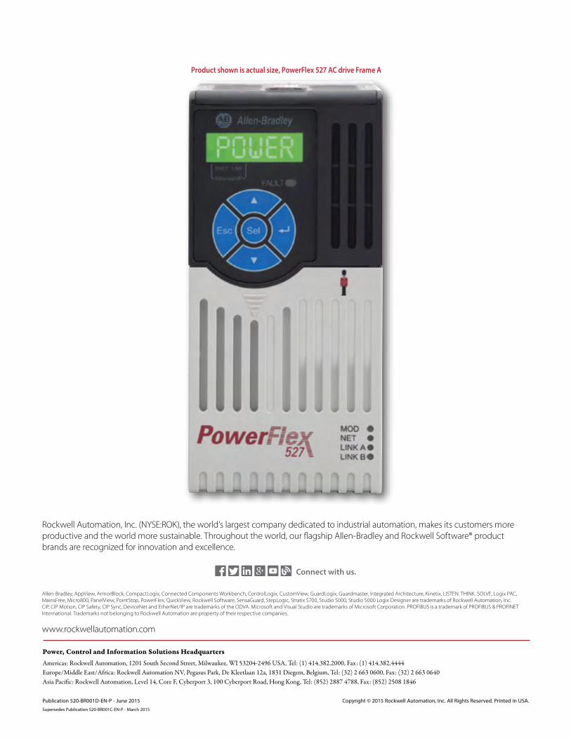
Product shown is actual size, PowerFlex 527 AC drive Frame A