Embed Size (px)
Citation preview

PowerFlex® 6000 Medium Voltage Variable Frequency DrivePublication 6000-UM001B-EN-P
User Manual

Important User Information
Read this document and the documents listed in the additional resources section about installation, configuration, and operation of this equipment before you install, configure, operate, or maintain this product. Users are required to familiarize themselves with installation and wiring instructions in addition to requirements of all applicable codes, laws, and standards.
Activities including installation, adjustments, putting into service, use, assembly, disassembly, and maintenance are required to be carried out by suitably trained personnel in accordance with applicable code of practice.
If this equipment is used in a manner not specified by the manufacturer, the protection provided by the equipment may be impaired.
In no event will Rockwell Automation, Inc. be responsible or liable for indirect or consequential damages resulting from the use or application of this equipment.
The examples and diagrams in this manual are included solely for illustrative purposes. Because of the many variables and requirements associated with any particular installation, Rockwell Automation, Inc. cannot assume responsibility or liability for actual use based on the examples and diagrams.
No patent liability is assumed by Rockwell Automation, Inc. with respect to use of information, circuits, equipment, or software described in this manual.
Reproduction of the contents of this manual, in whole or in part, without written permission of Rockwell Automation, Inc., is prohibited.
Throughout this manual, when necessary, we use notes to make you aware of safety considerations.
Labels may also be on or inside the equipment to provide specific precautions.
Allen-Bradley, Rockwell Software, Rockwell Automation, and TechConnect are trademarks of Rockwell Automation, Inc.
Trademarks not belonging to Rockwell Automation are property of their respective companies.
WARNING: Identifies information about practices or circumstances that can cause an explosion in a hazardous environment, which may lead to personal injury or death, property damage, or economic loss.
ATTENTION: Identifies information about practices or circumstances that can lead to personal injury or death, property damage, or economic loss. Attentions help you identify a hazard, avoid a hazard, and recognize the consequence.
IMPORTANT Identifies information that is critical for successful application and understanding of the product.
SHOCK HAZARD: Labels may be on or inside the equipment, for example, a drive or motor, to alert people that dangerous voltage may be present.
BURN HAZARD: Labels may be on or inside the equipment, for example, a drive or motor, to alert people that surfaces may reach dangerous temperatures.
ARC FLASH HAZARD: Labels may be on or inside the equipment, for example, a motor control center, to alert people to potential Arc Flash. Arc Flash will cause severe injury or death. Wear proper Personal Protective Equipment (PPE). Follow ALL Regulatory requirements for safe work practices and for Personal Protective Equipment (PPE).

Table of Contents
Preface Introduction. . . . . . . . . . . . . . . . . . . . . . . . . . . . . . . . . . . . . . . . . . . . . . . . . . . . . . . 7Who Should Use This Manual . . . . . . . . . . . . . . . . . . . . . . . . . . . . . . . . . . . . . . 7What Is Not in This Manual . . . . . . . . . . . . . . . . . . . . . . . . . . . . . . . . . . . . . . . . 7Additional Resources . . . . . . . . . . . . . . . . . . . . . . . . . . . . . . . . . . . . . . . . . . . . . . . 7General Precautions . . . . . . . . . . . . . . . . . . . . . . . . . . . . . . . . . . . . . . . . . . . . . . . . 8Service and Support . . . . . . . . . . . . . . . . . . . . . . . . . . . . . . . . . . . . . . . . . . . . . . . . 8
Commissioning Support . . . . . . . . . . . . . . . . . . . . . . . . . . . . . . . . . . . . . . . . 8
Chapter 1Introduction Safety Considerations . . . . . . . . . . . . . . . . . . . . . . . . . . . . . . . . . . . . . . . . . . . . . . 9
Environmental Conditions . . . . . . . . . . . . . . . . . . . . . . . . . . . . . . . . . . . . . . . 10How it Works . . . . . . . . . . . . . . . . . . . . . . . . . . . . . . . . . . . . . . . . . . . . . . . . . . . 10
Cascaded “H” Bridge (CHB) Topology . . . . . . . . . . . . . . . . . . . . . . . . 10Simplified Electrical Diagrams . . . . . . . . . . . . . . . . . . . . . . . . . . . . . . . . . . . . 12Standards Compliance. . . . . . . . . . . . . . . . . . . . . . . . . . . . . . . . . . . . . . . . . . . . 15
Chapter 2Drive System Layout Elevation Drawings . . . . . . . . . . . . . . . . . . . . . . . . . . . . . . . . . . . . . . . . . . . . . . 17
Isolation Transformer Cabinet . . . . . . . . . . . . . . . . . . . . . . . . . . . . . . . . . . . . 18Isolation Transformer . . . . . . . . . . . . . . . . . . . . . . . . . . . . . . . . . . . . . . . . 20Isolation Transformer Temperature Monitor . . . . . . . . . . . . . . . . . . . 21Isolation Transformer Auxiliary Cooling Fans . . . . . . . . . . . . . . . . . . 22Top-mounted Main Cooling Fan(s) . . . . . . . . . . . . . . . . . . . . . . . . . . . 22Incoming Line Power Cable Connections . . . . . . . . . . . . . . . . . . . . . . 22Outgoing Motor Cable Connections. . . . . . . . . . . . . . . . . . . . . . . . . . . 22Door Position Limit Switch . . . . . . . . . . . . . . . . . . . . . . . . . . . . . . . . . . . 23Voltage Sensing Board . . . . . . . . . . . . . . . . . . . . . . . . . . . . . . . . . . . . . . . . 24
Power Module Cabinet . . . . . . . . . . . . . . . . . . . . . . . . . . . . . . . . . . . . . . . . . . . 25Power Modules. . . . . . . . . . . . . . . . . . . . . . . . . . . . . . . . . . . . . . . . . . . . . . . 26Hall Effect Current Sensors (HECs) . . . . . . . . . . . . . . . . . . . . . . . . . . . 28Top-mounted Main Cooling Fan(s) . . . . . . . . . . . . . . . . . . . . . . . . . . . 28
LV Control Cabinet. . . . . . . . . . . . . . . . . . . . . . . . . . . . . . . . . . . . . . . . . . . . . . 29Control Unit (all modules). . . . . . . . . . . . . . . . . . . . . . . . . . . . . . . . . . . . 30PLC. . . . . . . . . . . . . . . . . . . . . . . . . . . . . . . . . . . . . . . . . . . . . . . . . . . . . . . . . 32HMI . . . . . . . . . . . . . . . . . . . . . . . . . . . . . . . . . . . . . . . . . . . . . . . . . . . . . . . . 32UPS . . . . . . . . . . . . . . . . . . . . . . . . . . . . . . . . . . . . . . . . . . . . . . . . . . . . . . . . . 32
Chapter 3Setup and Operation Overview . . . . . . . . . . . . . . . . . . . . . . . . . . . . . . . . . . . . . . . . . . . . . . . . . . . . . . . . 33
Main Interface . . . . . . . . . . . . . . . . . . . . . . . . . . . . . . . . . . . . . . . . . . . . . . . . . . . 33Drive Setup and Configuration Controls . . . . . . . . . . . . . . . . . . . . . . . 34Status Indicators . . . . . . . . . . . . . . . . . . . . . . . . . . . . . . . . . . . . . . . . . . . . . 34Operation Bar. . . . . . . . . . . . . . . . . . . . . . . . . . . . . . . . . . . . . . . . . . . . . . . . 35Setup and Monitor Box . . . . . . . . . . . . . . . . . . . . . . . . . . . . . . . . . . . . . . . 35
Rockwell Automation Publication 6000-UM001B-EN-P - October 2014 3

Table of Contents
Main Interface Controls . . . . . . . . . . . . . . . . . . . . . . . . . . . . . . . . . . . . . . . . . . 35Set Frequency (Hz) . . . . . . . . . . . . . . . . . . . . . . . . . . . . . . . . . . . . . . . . . . . 36Drive Operation Controls . . . . . . . . . . . . . . . . . . . . . . . . . . . . . . . . . . . . . 37View Version Information. . . . . . . . . . . . . . . . . . . . . . . . . . . . . . . . . . . . . 38
Alarm . . . . . . . . . . . . . . . . . . . . . . . . . . . . . . . . . . . . . . . . . . . . . . . . . . . . . . . . . . . 39Alarm History. . . . . . . . . . . . . . . . . . . . . . . . . . . . . . . . . . . . . . . . . . . . . . . . 40
Trends . . . . . . . . . . . . . . . . . . . . . . . . . . . . . . . . . . . . . . . . . . . . . . . . . . . . . . . . . . 41View Voltage, Current or Frequency Trends . . . . . . . . . . . . . . . . . . . . 42
Operation . . . . . . . . . . . . . . . . . . . . . . . . . . . . . . . . . . . . . . . . . . . . . . . . . . . . . . . 43Confirm Bypass Mode . . . . . . . . . . . . . . . . . . . . . . . . . . . . . . . . . . . . . . . . 43Choose Local/Remote Operation . . . . . . . . . . . . . . . . . . . . . . . . . . . . . . 45Open/Close Drive Input and Output Contactors . . . . . . . . . . . . . . . 46Open/Close Bypass Contactors . . . . . . . . . . . . . . . . . . . . . . . . . . . . . . . . 47
Settings . . . . . . . . . . . . . . . . . . . . . . . . . . . . . . . . . . . . . . . . . . . . . . . . . . . . . . . . . . 48System Settings . . . . . . . . . . . . . . . . . . . . . . . . . . . . . . . . . . . . . . . . . . . . . . . 48User Settings . . . . . . . . . . . . . . . . . . . . . . . . . . . . . . . . . . . . . . . . . . . . . . . . . 50Change User Parameters . . . . . . . . . . . . . . . . . . . . . . . . . . . . . . . . . . . . . . 50Setup Settings . . . . . . . . . . . . . . . . . . . . . . . . . . . . . . . . . . . . . . . . . . . . . . . . 53View/Change P or T Parameters . . . . . . . . . . . . . . . . . . . . . . . . . . . . . . . 53Restore “P” or “T” Parameters . . . . . . . . . . . . . . . . . . . . . . . . . . . . . . . . . 55
Chapter 4Parameters and Function Codes P Parameters . . . . . . . . . . . . . . . . . . . . . . . . . . . . . . . . . . . . . . . . . . . . . . . . . . . . . 57
T Parameters. . . . . . . . . . . . . . . . . . . . . . . . . . . . . . . . . . . . . . . . . . . . . . . . . . . . . 63Alarm List . . . . . . . . . . . . . . . . . . . . . . . . . . . . . . . . . . . . . . . . . . . . . . . . . . . . . . . 64
Chapter 5Preventative Maintenance and Component Replacement
Safety. . . . . . . . . . . . . . . . . . . . . . . . . . . . . . . . . . . . . . . . . . . . . . . . . . . . . . . . . . . . 77Introduction . . . . . . . . . . . . . . . . . . . . . . . . . . . . . . . . . . . . . . . . . . . . . . . . . . . . . 77
Daily Inspection . . . . . . . . . . . . . . . . . . . . . . . . . . . . . . . . . . . . . . . . . . . . . . 78Regular Maintenance Intervals . . . . . . . . . . . . . . . . . . . . . . . . . . . . . . . . . 78
Physical Checks (No Medium Voltage or Control Power) . . . . . . . . . . . 79Power Connection Inspection . . . . . . . . . . . . . . . . . . . . . . . . . . . . . . . . . 79Physical Inspection . . . . . . . . . . . . . . . . . . . . . . . . . . . . . . . . . . . . . . . . . . . 79Medium Voltage Testing . . . . . . . . . . . . . . . . . . . . . . . . . . . . . . . . . . . . . . 80Maintenance after a Fault Condition . . . . . . . . . . . . . . . . . . . . . . . . . . . 80
Final Report . . . . . . . . . . . . . . . . . . . . . . . . . . . . . . . . . . . . . . . . . . . . . . . . . . . . . 80Isolation Transformer Cabinet . . . . . . . . . . . . . . . . . . . . . . . . . . . . . . . . . . . . 81
Replace/Clean Door Mounted Air Filters. . . . . . . . . . . . . . . . . . . . . . . 81Inspect Top Mounted Main Cooling Fans . . . . . . . . . . . . . . . . . . . . . . 82Replace Top Mounted Main Cooling Fans. . . . . . . . . . . . . . . . . . . . . . 83Fan Balance . . . . . . . . . . . . . . . . . . . . . . . . . . . . . . . . . . . . . . . . . . . . . . . . . . 84Inspect Isolation Transformer Auxiliary Cooling Fans . . . . . . . . . . . 85Replace Isolation Transformer Auxiliary Cooling Fans. . . . . . . . . . . 86Inspect Isolation Transformer . . . . . . . . . . . . . . . . . . . . . . . . . . . . . . . . . 86Inspect Voltage Sensing Board . . . . . . . . . . . . . . . . . . . . . . . . . . . . . . . . . 87
4 Rockwell Automation Publication 6000-UM001B-EN-P - October 2014

Table of Contents
Replace Voltage Sensing Board . . . . . . . . . . . . . . . . . . . . . . . . . . . . . . . . 87Inspect Door Position Limit Switch. . . . . . . . . . . . . . . . . . . . . . . . . . . . 88Replace Door Position Limit Switch . . . . . . . . . . . . . . . . . . . . . . . . . . . 89
Power Module Cabinet . . . . . . . . . . . . . . . . . . . . . . . . . . . . . . . . . . . . . . . . . . . 90Inspect, Clean, or Replace Door Mounted Air Filters . . . . . . . . . . . . 90Inspect or Replace Top Mounted Main Cooling Fans . . . . . . . . . . . 90Inspect Power Modules . . . . . . . . . . . . . . . . . . . . . . . . . . . . . . . . . . . . . . . 90Replace Power Module. . . . . . . . . . . . . . . . . . . . . . . . . . . . . . . . . . . . . . . . 91Replace Power Module Fuses . . . . . . . . . . . . . . . . . . . . . . . . . . . . . . . . . . 97Inspect or Replace HECS . . . . . . . . . . . . . . . . . . . . . . . . . . . . . . . . . . . . . 99Inspect or Replace Door Position Limit Switch . . . . . . . . . . . . . . . . 100
LV Control Cabinet. . . . . . . . . . . . . . . . . . . . . . . . . . . . . . . . . . . . . . . . . . . . . 101Inspect AC/DC Power Supplies . . . . . . . . . . . . . . . . . . . . . . . . . . . . . . 101Replace AC/DC Power Supplies. . . . . . . . . . . . . . . . . . . . . . . . . . . . . . 102Inspect UPS . . . . . . . . . . . . . . . . . . . . . . . . . . . . . . . . . . . . . . . . . . . . . . . . 104Replace UPS . . . . . . . . . . . . . . . . . . . . . . . . . . . . . . . . . . . . . . . . . . . . . . . . 105Replace UPS Batteries . . . . . . . . . . . . . . . . . . . . . . . . . . . . . . . . . . . . . . . 106Inspect PLC . . . . . . . . . . . . . . . . . . . . . . . . . . . . . . . . . . . . . . . . . . . . . . . . 108Inspect/Replace Control Unit or Control Boards . . . . . . . . . . . . . . 108Inspect the HMI . . . . . . . . . . . . . . . . . . . . . . . . . . . . . . . . . . . . . . . . . . . . 111Replace the HMI . . . . . . . . . . . . . . . . . . . . . . . . . . . . . . . . . . . . . . . . . . . . 111Replace LV Control Relays . . . . . . . . . . . . . . . . . . . . . . . . . . . . . . . . . . . 113Replace LV Control Circuit Breakers . . . . . . . . . . . . . . . . . . . . . . . . . 114Inspect Coils . . . . . . . . . . . . . . . . . . . . . . . . . . . . . . . . . . . . . . . . . . . . . . . . 116Inspect Contacts . . . . . . . . . . . . . . . . . . . . . . . . . . . . . . . . . . . . . . . . . . . . 116Inspect Pilot Lights . . . . . . . . . . . . . . . . . . . . . . . . . . . . . . . . . . . . . . . . . . 116Inspect Locking and Interlocking Devices . . . . . . . . . . . . . . . . . . . . . 116
Connections . . . . . . . . . . . . . . . . . . . . . . . . . . . . . . . . . . . . . . . . . . . . . . . . . . . . 117Inspect LV Component Terminal and Plug-in Connections . . . . 117Inspect Medium Voltage Cable Connections . . . . . . . . . . . . . . . . . . 117Inspect Power Cable and Control Wire Terminals . . . . . . . . . . . . . 117Inspect Transformer Secondary Windings . . . . . . . . . . . . . . . . . . . . . 117Inspect Power Module Input and Output Power Connections . . 118
General . . . . . . . . . . . . . . . . . . . . . . . . . . . . . . . . . . . . . . . . . . . . . . . . . . . . . . . . 118Review Firmware and Hardware . . . . . . . . . . . . . . . . . . . . . . . . . . . . . . 118Inspect/Review Spare Parts. . . . . . . . . . . . . . . . . . . . . . . . . . . . . . . . . . . 118
Appendix ATechnical Specifications . . . . . . . . . . . . . . . . . . . . . . . . . . . . . . . . . . . . . . . . . . . . . . . . . . . . . . . . . . . . . . . . 119
Appendix BCatalog Number Explanation . . . . . . . . . . . . . . . . . . . . . . . . . . . . . . . . . . . . . . . . . . . . . . . . . . . . . . . . . . . . . . . . 121
Appendix CPreventative Maintenance Schedule PowerFlex 6000 Maintenance Schedule . . . . . . . . . . . . . . . . . . . . . . . . . . . 123
Rockwell Automation Publication 6000-UM001B-EN-P - October 2014 5
Table of Contents
Appendix DSpare Parts Spare Parts List. . . . . . . . . . . . . . . . . . . . . . . . . . . . . . . . . . . . . . . . . . . . . . . . . . 127
Appendix ETorque Requirements Torque Requirements . . . . . . . . . . . . . . . . . . . . . . . . . . . . . . . . . . . . . . . . . . . 129
Index
6 Rockwell Automation Publication 6000-UM001B-EN-P - October 2014
Preface
Introduction This document provides procedural information for managing daily or recurring tasks involving PowerFlex 6000 medium voltage variable frequency drives.
Who Should Use This Manual This manual is intended for use by personnel familiar with operating medium voltage and solid-state variable speed drive equipment. The manual contains material that enables operation and regular maintenance of the drive system.
What Is Not in This Manual This manual provides information specific to maintaining the PowerFlex 6000 medium voltage variable frequency drive. It does not include topics such as:
• Dimensional and electrical drawings generated for each customer’s order• Spare parts lists compiled for each customer’s order
Please refer to the following documents for additional product detail or instruction relating to PowerFlex 6000 drives:
• PowerFlex 6000 Medium Voltage Variable Frequency Drive Shipping, Handling, and Installation Instructions (6000-IN006_-EN-P). This document provides procedural information for physically unloading, moving, and installing PowerFlex 6000 medium voltage drives.
• PowerFlex 6000 Medium Voltage Variable Frequency Drive Commissioning Manual (6000-IN007_-EN-P). This document provides information for commissioning PowerFlex 6000 medium voltage drives.
Rockwell Automation provides the site- and installation-specific electrical and design information for each drive during the order process cycle. If they are not available on site with the drive, contact Rockwell Automation.
Additional Resources These documents contain additional information concerning related products from Rockwell Automation.
You can view or download publications athttp:/www.rockwellautomation.com/literature/. To order paper copies of technical documentation, contact your local Allen-Bradley distributor or Rockwell Automation sales representative.
Resource Description
Industrial Automation Wiring and Grounding Guidelines, publication 1770-4.1
Provides general guidelines for installing a Rockwell Automation industrial system.
Product Certifications website, http://www.ab.com Provides declarations of conformity, certificates, and other certification details.
Rockwell Automation Publication 6000-UM001B-EN-P - October 2014 7

Preface
General Precautions
Service and Support Commissioning Support
After installation, Rockwell Automation is responsible for commissioning activities for the PowerFlex 6000 product line. Contact your local Rockwell Automation sales representative to arrange commissioning.
Rockwell Automation support includes, but is not limited to:• quoting and managing product on-site start-ups• quoting and managing field modification projects• quoting and managing customer in-house and on-site product training
The user or its representatives are responsible for pre-commissioning activities to prepare the drive for commissioning. Failure to complete these activities prior to the commissioning process will delay the start-up of the drive. Please refer to the Pre-commissioning Checklist in the PowerFlex 6000 Medium Voltage Variable Frequency Drive Shipping, Handling, and Installation Instructions (6000-IN006_-EN-P).
ATTENTION: This drive contains ESD (Electrostatic Discharge) sensitive parts and assemblies. Static control precautions are required when installing, testing, servicing or repairing this assembly. Component damage may result if ESD control procedures are not followed. If you are not familiar with static control procedures, reference Allen-Bradley publication 8000-4.5.2, “Guarding Against Electrostatic Damage” or any other applicable ESD protection handbook.
ATTENTION: An incorrectly applied or installed drive can result in component damage or a reduction in product life. Wiring or application errors, such as, undersizing the motor, incorrect or inadequate AC supply, or excessive ambient temperatures may result in malfunction of the system.
ATTENTION: Only personnel familiar with the PowerFlex 6000 Adjustable Speed Drive (ASD) and associated machinery should plan or implement the installation, start-up and subsequent maintenance of the system. Failure to comply may result in personal injury and/or equipment damage.
8 Rockwell Automation Publication 6000-UM001B-EN-P - October 2014

Chapter 1
Introduction
Around the world, Allen-Bradley® PowerFlex® medium voltage drives from Rockwell Automation have built a reputation for providing efficient and reliable motor control for industry's most demanding applications. From the hardware designed to help optimize production to the power of networked control platforms, users can quickly and easily gain access to valuable information from their systems. Better information leads to higher asset availability, reduced energy and maintenance costs, and asset and personnel protection - all resulting in an increased return on your investment and real bottom-line savings. No matter where your applications are located - and whether your requirements are simple or complex, count on PowerFlex medium voltage drives for the optimal solution.
Safety Considerations
Lockout and tagout the device feeding power to the input of the drive before performing any drive maintenance or component replacements. After the input device cabinet doors are opened, immediately test the outgoing power cables feeding the drive with a live-line tool (hot stick) while wearing high voltage gloves. Repeat the live-line tool (hot stick) testing at the drive incoming line power cable connections to verify that medium voltage is not present. Pay special attention to any capacitors connected to medium voltage that can retain a charge for a period of time. Only after the drive equipment has been verified as isolated and de-energized can subsequent work be performed. Even though the input to the drive may be open, it is still possible for hazardous voltage to be present.
SHOCK HAZARD: Energized industrial control equipment can be dangerous. Severe injury or death can result from electrical shock, burn, or unintended actuation of control equipment. Hazardous voltages may exist in the drive cabinet even with the input circuit breaker in the off position. If it is necessary to work in the vicinity of energized equipment, the safety related work practices outlined in Electrical Safety requirements for Employee Work places must be followed. Before attempting any work, verify the system has been locked out and tested to have no potential.
Rockwell Automation Publication 6000-UM001B-EN-P - October 2014 9

Chapter 1 Introduction
Refer to national and local safety guidelines for detailed procedures on how to safely isolate the equipment from hazards.
Environmental Conditions • Elevation above sea level must be less than 1000 m (3250 ft)(1).• Ambient air temperature must be between 0...40°C (32...104°F)(2).• Relative humidity must be less than 90%, non-condensing.• The drive must be installed indoors; there must be no dripping water or
other fluids in the room.• Cooling air must be clean without significant concentrations of sand,
corrosive or conductive dust (defined by IEC 721-1 as being less than 0.2 mg/m of dust), or explosive gas.
• Free from significant vibration.• The drive must be anchored on a level floor. Please refer to the dimension
drawing for the anchor point sizes and locations.
For the equipment to operate in conditions other than those specified, consult the local Rockwell Automation Sales Office.
How it Works Cascaded “H” Bridge (CHB) Topology
The proven CHB topology combines an integrally mounted phase shifting isolation transformer and series-connected power modules for each phase. In addition to stepping down the input voltage, the isolation transformer also provides two other principal functions:
• Mitigate common mode voltage stress so motors with standard insulation levels can be used.
• Reduce Total Harmonic Distortion (THD), due to the phase shifting of its secondary windings, so input side harmonics don’t negatively impact the plant or utility power grid.
ATTENTION: The national and local electrical codes outline provisions for safely installing and working on electrical equipment. Installation must comply with specifications regarding wire type, conductor sizes, branch circuit protection and disconnect devices. Failure to do so may result in personal injury and/or equipment damage.
(1) Options are available for operation up to 3000 m.a.s.l. However, these must be stated at the time of order and cannot be retrofitted in the field.
(2) Options are available for ambient temperatures up to 50 ºC. However, these must be stated at the time of order and cannot be retrofitted in the field.
10 Rockwell Automation Publication 6000-UM001B-EN-P - October 2014

Introduction Chapter 1
A number of identical low voltage power modules are series-connected (cascaded) together to produce the medium voltage levels required to operate the motor.
The voltage step for each module is relatively small and a Pulse Width Modulation (PWM) switching pattern is used so output harmonics and torque pulsations at the motor are minimal, even at lower speeds. This technology is very motor friendly so standard motors can be used for new applications and it also is ideal for retrofitting existing motors. This also allows for the motor cable lengths required for most applications, without the requirement for output filtering.
This power module concept makes maintenance quick and easy. Each module has powerful built in diagnostics to identify and isolate a module needing replacement, in the unlikely event of a failure. This minimizes power module replacement time, so process uptime is maximized.
Figure 1 - 6/6.6 kV Example Power Structure
Input Power3 Phase AC
Power Modules
Isolation Transformer
Rockwell Automation Publication 6000-UM001B-EN-P - October 2014 11

Chapter 1 Introduction
Simplified Electrical Diagrams
Figure 2 - 3000V / 3300V (18 Pulse - 9 Power Modules)
Figure 3 - 6000V /6600V (36 Pulse - 18 Power Modules)
Figure 4 - 10,000V (54 Pulse - 27 Power Modules)
Isolation Transformer Secondary Windings
U
V
W
Isolation Transformer Secondary Windings
U
V
W
Isolation Transformer Secondary Windings
U
V
W
12 Rockwell Automation Publication 6000-UM001B-EN-P - October 2014
Introduction Chapter 1
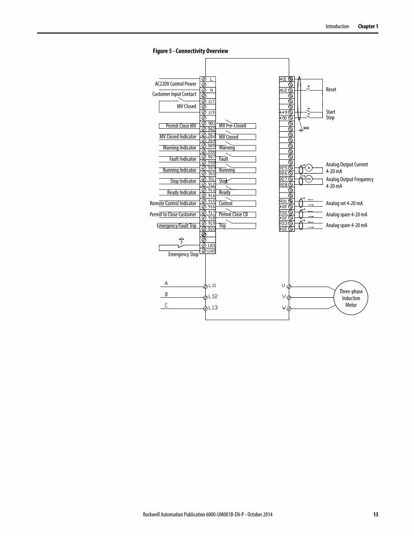
Figure 5 - Connectivity Overview
Reset
StartStop
Analog Output Current 4-20 mAAnalog Output Frequency 4-20 mA
Analog set 4-20 mA
Analog spare 4-20 mA
Analog spare 4-20 mA
AC220V Control Power
MV Closed
Customer Input Contact
Permit Close MV
MV Closed Indicator
Warning Indicator
Fault Indicator
Running Indicator
Stop Indicator
Ready Indicator
Remote Control Indicator
Permit to Close Customer
Emergency/Fault Trip
Emergency Stop
MV Pre-Closed
MV Closed
Warning
Fault
Running
Stop
Ready
Control
Permit Close CB
Trip
Three-phase Induction
Motor
Rockwell Automation Publication 6000-UM001B-EN-P - October 2014 13

Chapter 1 Introduction
Figure 6 - PowerFlex 6000 Principal Components
Generous space for terminating incoming line cables.
Generous space for terminating outgoing load cables.
Integrally mounted Multi-pulse Isolation Transformer (3 wires in & 3 wires out) ensures low line side harmonics and high input power factor
Cabinet ships in two sections to minimize shipping and handling issues.
All Power Modules are identical to minimize spare parts.
All Power Modules are designed for easy removal and replacement to minimize MTTR.
Power Module has a PWM pattern to reduce output harmonics
All MV doors are electrically interlocked with input switching device
Isolation Transformer Temperature Monitor
All door filters can be changed while the drive is running
All cooling fans are internally powered by a dedicated winding in the Isolation Transformer – no separate fan power supply is needed from customer
All MV doors are lockable
Intuitive, easy-to-use, color touchscreen HMI
Many communication modules are available, such as EtherNet I/P and Profibus DP
Automatic switchover (no trip) to internally supplied control power if customer-supplied single phase control power is lost
On-line UPS supplied as standard
Incoming Line Cables
Outgoing Load Cables
Isolation Transformer Power Modules
Door Filters
Transformer Temperature Monitor Cooling Fans
HMI
14 Rockwell Automation Publication 6000-UM001B-EN-P - October 2014
Introduction Chapter 1
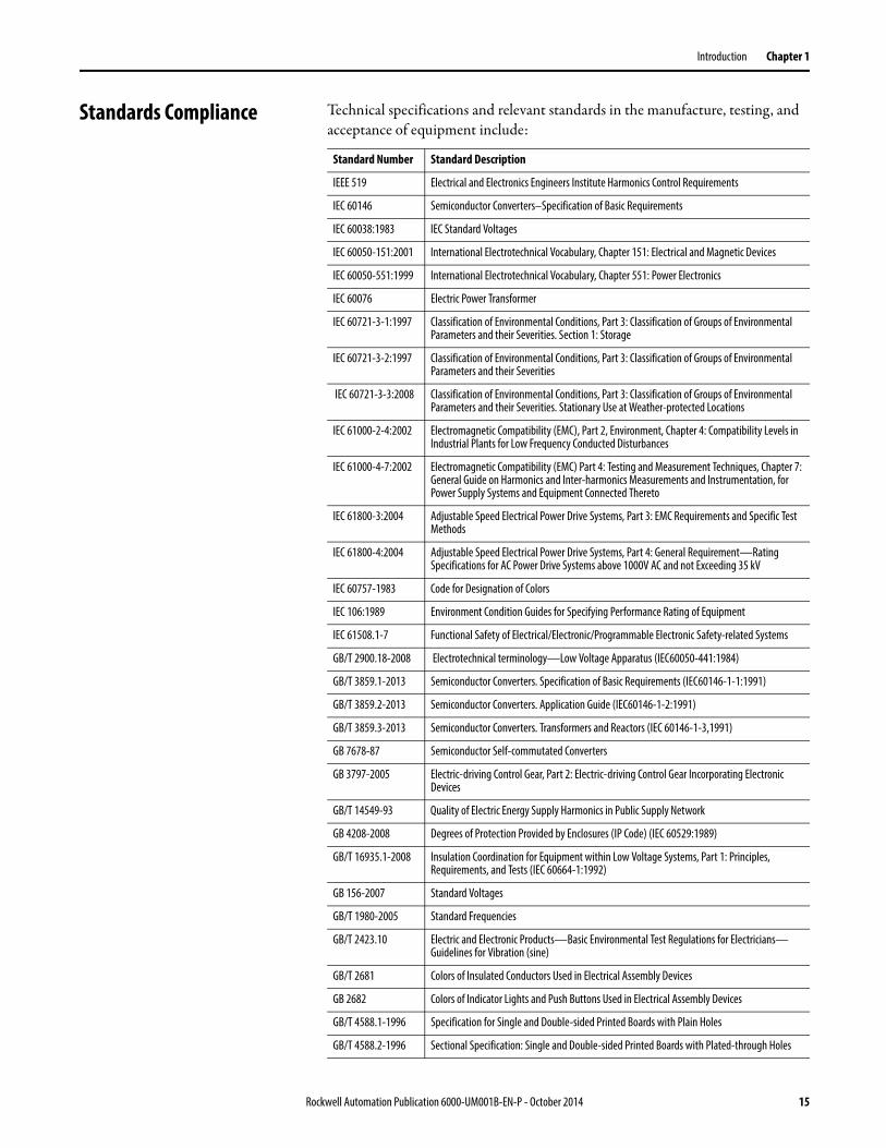
Standards Compliance Technical specifications and relevant standards in the manufacture, testing, and acceptance of equipment include:
Standard Number Standard Description
IEEE 519 Electrical and Electronics Engineers Institute Harmonics Control Requirements
IEC 60146 Semiconductor Converters–Specification of Basic Requirements
IEC 60038:1983 IEC Standard Voltages
IEC 60050-151:2001 International Electrotechnical Vocabulary, Chapter 151: Electrical and Magnetic Devices
IEC 60050-551:1999 International Electrotechnical Vocabulary, Chapter 551: Power Electronics
IEC 60076 Electric Power Transformer
IEC 60721-3-1:1997 Classification of Environmental Conditions, Part 3: Classification of Groups of Environmental Parameters and their Severities. Section 1: Storage
IEC 60721-3-2:1997 Classification of Environmental Conditions, Part 3: Classification of Groups of Environmental Parameters and their Severities
IEC 60721-3-3:2008 Classification of Environmental Conditions, Part 3: Classification of Groups of Environmental Parameters and their Severities. Stationary Use at Weather-protected Locations
IEC 61000-2-4:2002 Electromagnetic Compatibility (EMC), Part 2, Environment, Chapter 4: Compatibility Levels in Industrial Plants for Low Frequency Conducted Disturbances
IEC 61000-4-7:2002 Electromagnetic Compatibility (EMC) Part 4: Testing and Measurement Techniques, Chapter 7: General Guide on Harmonics and Inter-harmonics Measurements and Instrumentation, for Power Supply Systems and Equipment Connected Thereto
IEC 61800-3:2004 Adjustable Speed Electrical Power Drive Systems, Part 3: EMC Requirements and Specific Test Methods
IEC 61800-4:2004 Adjustable Speed Electrical Power Drive Systems, Part 4: General Requirement—Rating Specifications for AC Power Drive Systems above 1000V AC and not Exceeding 35 kV
IEC 60757-1983 Code for Designation of Colors
IEC 106:1989 Environment Condition Guides for Specifying Performance Rating of Equipment
IEC 61508.1-7 Functional Safety of Electrical/Electronic/Programmable Electronic Safety-related Systems
GB/T 2900.18-2008 Electrotechnical terminology—Low Voltage Apparatus (IEC60050-441:1984)
GB/T 3859.1-2013 Semiconductor Converters. Specification of Basic Requirements (IEC60146-1-1:1991)
GB/T 3859.2-2013 Semiconductor Converters. Application Guide (IEC60146-1-2:1991)
GB/T 3859.3-2013 Semiconductor Converters. Transformers and Reactors (IEC 60146-1-3,1991)
GB 7678-87 Semiconductor Self-commutated Converters
GB 3797-2005 Electric-driving Control Gear, Part 2: Electric-driving Control Gear Incorporating Electronic Devices
GB/T 14549-93 Quality of Electric Energy Supply Harmonics in Public Supply Network
GB 4208-2008 Degrees of Protection Provided by Enclosures (IP Code) (IEC 60529:1989)
GB/T 16935.1-2008 Insulation Coordination for Equipment within Low Voltage Systems, Part 1: Principles, Requirements, and Tests (IEC 60664-1:1992)
GB 156-2007 Standard Voltages
GB/T 1980-2005 Standard Frequencies
GB/T 2423.10 Electric and Electronic Products—Basic Environmental Test Regulations for Electricians—Guidelines for Vibration (sine)
GB/T 2681 Colors of Insulated Conductors Used in Electrical Assembly Devices
GB 2682 Colors of Indicator Lights and Push Buttons Used in Electrical Assembly Devices
GB/T 4588.1-1996 Specification for Single and Double-sided Printed Boards with Plain Holes
GB/T 4588.2-1996 Sectional Specification: Single and Double-sided Printed Boards with Plated-through Holes
Rockwell Automation Publication 6000-UM001B-EN-P - October 2014 15

Chapter 1 Introduction
GB 10233.2005 Basic Test Method for Low Voltage Switchgear and Controlgear
GB 12668.4-2006 Adjustable Speed Drive Electrical System, Part 4: General Requirement for Voltage up to 35 kV
GB 12668.3-2006 Adjustable Speed Drive Electrical System, Part 3: EMC Requirement and Testing Method
GB 12668.701-2013 Adjustable Speed Drive Electrical System, Part 701: Communication
GB/T 15139-94 General Technical Standard for Electrical Equipment Structure
GB/ 13422-2013 Semiconductor Converters—Electrical Test Methods
IEEE 519-1992 Practices and Requirements for Harmonic Control in Electrical Power Systems
GB/T 12668.4-2006 Adjustable Speed Electrical Power Drive Systems, Part 4: General Requirements. Rating Specifications for AC Power
GB1094.11-2007 Power Transformer, Part 11: Dry-type Transformer
Standard Number Standard Description
16 Rockwell Automation Publication 6000-UM001B-EN-P - October 2014

Chapter 2
Drive System Layout
There are two basic power cell configurations offered in the PowerFlex 6000 product line. For a drive amperage rating ≤200 A, a fixed-mounted power module design is supplied. Fixed-mounted modules are shipped installed in the drive. For a drive amperage rating of >200 A, a drawout power module design is supplied.
The PowerFlex 6000 drive is shipped in two sections, the Isolation Transformer Cabinet and the Power Module/LV Control Cabinet. Refer to PowerFlex 6000 Medium Voltage Variable Frequency Drive Shipping, Handling, and Installation Instructions (6000-IN006_-EN-P).
Elevation Drawings Figure 7 - Fixed-mounted Power Module Drive Configuration
Isolation Transformer Cabinet 18
Power Module Cabinet 25
LV Control Cabinet 29
Isolation Transformer Cabinet Power Module Cabinet LV Control Cabinet
Rockwell Automation Publication 6000-UM001B-EN-P - October 2014 17

Chapter 2 Drive System Layout
Figure 8 - Drawout Power Module Drive Configuration
Isolation Transformer Cabinet
Isolation Transformer Cabinet Power Module CabinetLV Control Cabinet
Isolation Transformer 20
Isolation Transformer Temperature Monitor 21
Isolation Transformer Auxiliary Cooling Fans 22
Top-mounted Main Cooling Fan(s) 22
Incoming Line Power Cable Connections 22
Outgoing Motor Cable Connections 22
Door Position Limit Switch 23
Voltage Sensing Board 24
18 Rockwell Automation Publication 6000-UM001B-EN-P - October 2014

Drive System Layout Chapter 2
Figure 9 - Isolation Transformer Cabinet (Fixed-mounted Power Module Drive Configuration)
Figure 10 - Isolation Transformer Cabinet (Drawout Power Module Drive Configuration)
Isolation Transformer
Cable Clamp
Voltage Sensing Board
Door PositionLimit Switches
L11L12L13
UVW
Isolation Transformer Auxiliary Cooling Fans
Power Cable Connections to Power Modules
Incoming Line PowerCable Connections
Outgoing Motor PowerCable Connections
Top-mounted Main Cooling Fan(s)
Cable Clamp
Voltage Sensing Board
Isolation Transformer
Door Position Limit Switches
L13 L12 L11 W V U
Incoming Line PowerCable Connections
Outgoing Motor PowerCable Connections
Isolation Transformer Auxiliary Cooling Fans
Top-mounted Main Cooling Fans
Rockwell Automation Publication 6000-UM001B-EN-P - October 2014 19

Chapter 2 Drive System Layout
Isolation Transformer
The primary winding of the isolation transformer is rated for the voltage of the distribution system. It is connected to the distribution system by the incoming line power cables. The secondary windings of the isolation transformer are connected to the inputs of the power modules. The secondary winding voltage is typically 690V, to feed the low voltage power modules.
There are between 9 and 27 three-phase secondary side windings, dependent on the motor voltage requirements. The phase relationship between the secondary windings are optimized to provide the highest reduction of line side harmonics.
The isolation transformer’s three-phase primary coils are oriented C, B, and A from left to right, as viewed from the front. The secondary windings are also divided into three principal sections from top to bottom. The upper third are to feed the power modules in the U output phase. The middle third are to feed the power modules in the V output phase. The bottom third are to feed the power modules in the W output phase (Figure 11).
Figure 11 - Isolation Transformer Primary and Secondary Winding Orientation
The secondary windings are brought out to corresponding vertical isolated stand-offs on the body of the transformer (orientated C, B, and A from left to right as viewed from the front).
PRIMARY WINDING INPUT
SECO
NDAR
Y WIN
DING
OUT
PUT
C (L3) B (L2) A (L1)
U
V
W
20 Rockwell Automation Publication 6000-UM001B-EN-P - October 2014

Drive System Layout Chapter 2
For drives with fixed-mounted power modules, the U and W phase interconnections to the isolation transformer secondary windings are on the front of the isolation transformer and the connections to the V phase are on the rear of the isolation transformer. The power cable connections to the power modules are made at the factory. Therefore, the field power cable connections need to be made at the isolation transformer secondary winding termination points (see 6000-IN006_-EN-P).
For drives with drawout power modules, all of the interconnections between the isolation transformer secondary windings and the power modules are made in the rear of the isolation transformer and the connection to the power modules are also in the rear. The power cable connections to the isolation transformer secondary winding termination point are made at the factory. Therefore, the field power cable connections must be made at the power module input points (see 6000-IN006_-EN-P).
Isolation Transformer Temperature Monitor
A discrete transformer temperature monitor is mounted on the LV door in the isolation transformer cabinet. Three temperature sensors are embedded in the isolation transformer. The monitor can be set to indicate an alarm condition or a trip condition, dependent on the temperature detected.
Figure 12 - Isolation Transformer Temperature Monitor
A separate user manual from the manufacturer is included in the documentation package.
Rockwell Automation Publication 6000-UM001B-EN-P - October 2014 21

Chapter 2 Drive System Layout
Isolation Transformer Auxiliary Cooling Fans
Six fans are mounted directly underneath the isolation transformer to force air directly through the windings - to ensure reliable cooling. A baffle structure surrounds the periphery of the transformer structure to ensure the cooling air does not bypass the interior of the transformer windings. These fans are powered by a tertiary winding in the isolation transformer. Separate fan control power is not required.
Top-mounted Main Cooling Fan(s)
The top mounted cooling fan(s) work with the auxiliary cooling fans to ensure reliable cooling of the isolation transformer. They ensure the air is exhausted from the cabinet by creating an induced draft.
Incoming Line Power Cable Connections
The incoming line cables connect to the line side terminals on the isolation transformer. Incoming line cables can be brought in through the top or bottom of the isolation transformer cabinet. Generous working space is provided, if stress cones are required. See publication 6000-IN006_-EN-P for additional details.
Outgoing Motor Cable Connections
The outgoing motor cables connect to a cable stand-off assembly on the cabinet side sheet (Fixed-mounted Power Module configuration) or to the cable stand-offs mounted on the Isolation Transformer (Drawout Power Module configuration).
The outgoing motor cables connect to output phase of the power module array. Outgoing motor cables can be brought in through the top or bottom of the isolation transformer cabinet. Generous working space is provided. See publication 6000-IN006_-EN-P for additional details.
22 Rockwell Automation Publication 6000-UM001B-EN-P - October 2014

Drive System Layout Chapter 2
Door Position Limit Switch
Each cabinet door that allows access to medium voltage components is lockable and also has a Guardmaster® safety limit switch. If the cabinet door is opened when the input switching device feeding power to the drive is closed, the input device will be tripped off.
Figure 13 - Door Position Limit Switch Location
ATTENTION: The door position interlock is a safety feature. It must not be used solely as a part of the plant operation process to ensure the drive has been disconnected from input medium voltage. Keep the medium voltage doors locked as standard practice. If access to the medium voltage rated cabinets is required, always go to the input device feeding the drive to verify if it is open. Lock out and tagout the input device before performing any work on the drive or bypass units.
Door Position Limit Switch
Rockwell Automation Publication 6000-UM001B-EN-P - October 2014 23

Chapter 2 Drive System Layout
Voltage Sensing Board
The Voltage Sensing Board (VSB) is connected to the drive output terminals that connect to the motor. The VSB converts motor voltage to low voltage levels which allows the drive to monitor the output voltage to the motor.
Figure 14 - Voltage Sensing Board
Figure 15 - Power Cabling Overview (3.3 kV Fixed-mounted Power Module Configuration)
L11
L12
L13
A1B1C1
A2B2C2
A3B3C3
A4B4C4
A5B5C5
A6B6C6
A7B7C7
A8B8C8
A9B9C9
U
V
W
PC A1
PC A2
PC A3
PC B1
PC B2
PC B3
PC C1
PC C2
PC C3
U
V
W
Input power 3-phase AC any voltage
Isolation Transformer
Motor
Voltage Sensing Board
Isolation Transformer Cabinet Power Module/LV Control Cabinet
24 Rockwell Automation Publication 6000-UM001B-EN-P - October 2014
Drive System Layout Chapter 2
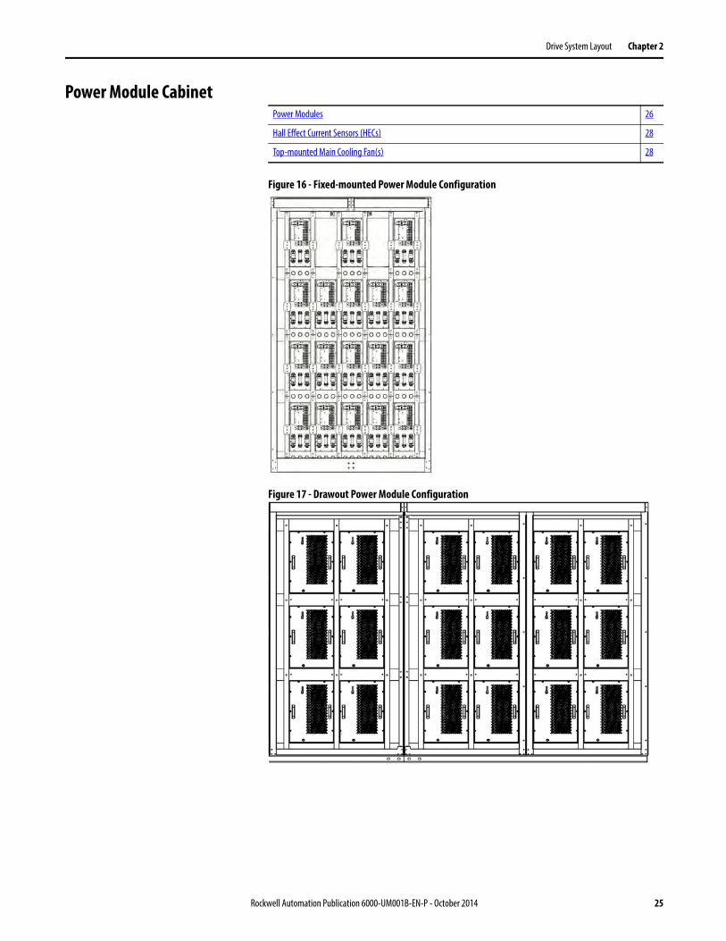
Power Module Cabinet
Figure 16 - Fixed-mounted Power Module Configuration
Figure 17 - Drawout Power Module Configuration
Power Modules 26
Hall Effect Current Sensors (HECs) 28
Top-mounted Main Cooling Fan(s) 28
Rockwell Automation Publication 6000-UM001B-EN-P - October 2014 25

Chapter 2 Drive System Layout
Power Modules
Power Modules are available in a wide variety of amperage ratings relating to the required motor current. Power Modules rated up to and including 200 A are fixed-mounted in the drive and ship already installed.
Drawout power modules are supplied for a drive current rating of >200 A. The power modules are shipped separately and must be installed in the cabinet. A Power Module lift cart is included and shipped together with the other components.
Basic Principle of Power Module
The Power Module combines a three phase rectifier and an “H” bridge inverter, powered from the secondary side windings of the Isolation Transformer. After rectifying and filtering, it outputs AC current with variable frequency and variable voltage under the control of four IGBTs using a PWM switching pattern. Several Power Modules, after being connected in series and superposed, can output three-phase AC current with adjustable frequency and voltage to control an AC motor.
Figure 18 - Low Voltage Power Module
Control signals to the Power Module and the feedback signals from the Power Module are transmitted by fiber optic cables which provide electrical isolation between the medium voltage and low voltage sections of the drive, and protects against electromagnetic interference.
Although the voltage produced by each power unit is typically less than 690V, the voltage-to-ground can reach the VFD rated output voltage, if operating at rated frequency.
The control signals from the main control unit, through the optical-electrical converter, are sent to the Power Module control board for further processing and to the corresponding gate drive circuits to turn the IGBTs on or off.
Input U
Input V
Input W
Fuse 1
Fuse 2
Three-phase Diode Rectifier Bridge
DC BusCapacitor Network
Single Phase IGBT Inverter Network
IGBT 1 IGBT 2
Output A Output B
D1 D2 D3
D4 D5 D6
C1 R1
C2 R2
C3 R3
26 Rockwell Automation Publication 6000-UM001B-EN-P - October 2014

Drive System Layout Chapter 2
The status information of the Power Module is transmitted through the electrical-optical converter and sent to the main control unit. When there is a fault, the main control unit sends control signals to lockout or bypass the affected Power Module.
The Power Module cabinet consists of Power Modules, current transformers and high-voltage cable.
The Power Modules are divided evenly into three phases (U, V, and W). The units in each phase are connected end-to-end at the output terminals. Then individual phases are formed, using a star connection. Current transformers are installed into the U phase and W phase.
Different models of Power Modules are used for VFDs of different power ratings (Figure 19).
Figure 19 - Typical Fixed-mounted Power Module
Line Terminals
Fuse
Optic Fiber Socketand Status Indicator
Output Terminal
Rockwell Automation Publication 6000-UM001B-EN-P - October 2014 27

Chapter 2 Drive System Layout
Table 1 - Power Module Ratings
Hall Effect Current Sensors (HECs)
The Hall Effect Current Sensors are current transformers capable of measuring current throughout the output frequency range of the drive. They monitor the current waveform in each of the phases going to the motor and provide feedback to the control system.
Top-mounted Main Cooling Fan(s)
The Top-mounted Cooling Fans ensure reliable cooling of the Power Modules. They draw cool air in through the vents in the Power Module Cabinet doors, through the Power Modules, and exhaust the heated air out through the top of the cabinet.
Catalog Number Spare Part Number Current Rating (Amps)
TPUxx/030-AC3 HTPUXX/030-AC3-R 30
TPUxx/040-AC3 HTPUXX/040-AC3-R 40
TPUxx/050-AC3 HTPUXX/050-AC3-R 50
TPUxx/060-AC3 HTPUXX/060-AC3-R 60
TPUxx/075-AC3 HTPUXX/075-AC3-R 75
TPUxx/080-AC3 HTPUXX/080-AC3-R 80
TPUxx/100-AC3 HTPUXX/100-AC3-R 100
TPUxx/120-AC3 HTPUXX/120-AC3-R 120
TPUxx/150-AC3 HTPUXX/150-AC3-R 150
TPUxx/180-AC3 HTPUXX/180-AC3-R 180
TPUxx/200-AC3 HTPUXX/200-AC3-R 200
TPUxx/300-AC3 HTPUXX/300-AC3-R 300
TPUxx/380-AC3 HTPUXX/380-AC3-R 380
TPUxx/420-AC3 HTPUXX/420-AC3-R 420
28 Rockwell Automation Publication 6000-UM001B-EN-P - October 2014

Drive System Layout Chapter 2
LV Control Cabinet
The LV Control Cabinet consists of the Control Unit, the human-machine Interface (HMI), PLC, AC/DC power supplies, contactors and relays.
The HMI is located on the front door of the LV Control Cabinet, where an operator can setup, monitor, and control the drive.
Control Unit (all modules) 30
PLC 32
HMI 32
UPS 32
Control Unit
PLC
LV Circuit Breakers
LV Control Relays
UPS
Rockwell Automation Publication 6000-UM001B-EN-P - October 2014 29
Chapter 2 Drive System Layout
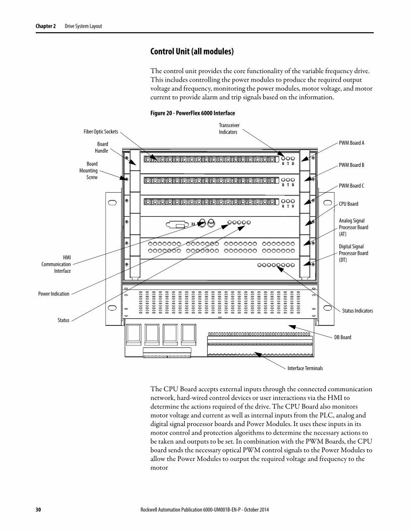
Control Unit (all modules)
The control unit provides the core functionality of the variable frequency drive. This includes controlling the power modules to produce the required output voltage and frequency, monitoring the power modules, motor voltage, and motor current to provide alarm and trip signals based on the information.
Figure 20 - PowerFlex 6000 Interface
The CPU Board accepts external inputs through the connected communication network, hard-wired control devices or user interactions via the HMI to determine the actions required of the drive. The CPU Board also monitors motor voltage and current as well as internal inputs from the PLC, analog and digital signal processor boards and Power Modules. It uses these inputs in its motor control and protection algorithms to determine the necessary actions to be taken and outputs to be set. In combination with the PWM Boards, the CPU board sends the necessary optical PWM control signals to the Power Modules to allow the Power Modules to output the required voltage and frequency to the motor
Transceiver Indicators
PWM Board A
PWM Board B
PWM Board C
CPU Board
Analog Signal Processor Board (AT)
Digital Signal Processor Board (DT)
Status Indicators
Interface Terminals
Fiber Optic Sockets
BoardHandle
BoardMounting
Screw
HMICommunication
Interface
Power Indication
Status
DB Board
30 Rockwell Automation Publication 6000-UM001B-EN-P - October 2014

Drive System Layout Chapter 2
Figure 21 - Control Unit Layout
Table 2 - Control Unit description
HMI
PWM Board A
DCS
Phase APower Modules
Fieldbus
VSB
HECS
PLC
Communication Board
PWM Board B PWM Board C
Phase CPower Modules
DT AT
DB
CPU Board
Phase BPower Modules
RJ45 Modbus TCP/IP
RS-485 Modbus
Modbus
Board FunctionPWM Board A, B, C Output PWM and control signals to Power Modules
Collect and process fault and state information from Power Modules to CPU boardEach phase PWM board can control up to nine power cells
CPU Board Process analog input signals, switch and fault information, control DA and switch signal output, realize V/F algorithm, set and change parameters in communication with HMI
Analog Signal Processor Board (AT)
Collect and process analog input signals to CPU Board, output analog signals processed by DT board
Digital Signal Processor Board (DT)
Collect and output digital signals, digital to analog conversion function
DB Board Acts as a base board in the Control Unit and interfaces the digital and analog signal cablesConnectorHMI Communication Interface
Connection between HMI and Control Unit. Provides inputs from the HMI and PLC to the CPU Board
Fiber Optic Socket Connection between Power Modules and Control Unit (two per module)Interface Terminals Connects external inputs, outputs and the CPU BoardStatus IndicatorsPhase control board transceiver indicator light
B: board healthy indicator T: transmit data to power module indicator R: receive data from power module indicator
CPU Board Indicator Lights5V 5V power supply indicator 3.3V 3.3V power supply indicatorFPGA FPGA healthy indicatorDSP1 DSP1 healthy indicatorDSP2 DSP2 healthy indicator
Rockwell Automation Publication 6000-UM001B-EN-P - October 2014 31

Chapter 2 Drive System Layout
PLC
The PowerFlex 6000 uses a Micro850 PLC to perform many of its internal control functions. The PLC controls and monitors the cooling fans, input and bypass switching devices, door switch status, etc. The PLC is also responsible for interfacing with the user's automation control system via many optional communication protocols. Standard communication protocols are EtherNet/IP, Modbus/TCP Server and Modbus RTU. Optional communication modules are available to support other communication protocols.
Figure 22 - PLC Location
HMI
The PowerFlex 6000 HMI is a PanelView Plus 700 series, catalog number 2711P-T7C4D9.
The HMI is connected to the Master Control board through a communication interface (standard RJ45 EtherNet/IP connection). The HMI configures operating parameters and input operation commands, and displays the operation status, operation parameters, and fault messages.
UPS
The UPS supplies power to the LV Control cabinet using internal batteries if the customer-supplied control power and isolation transformer control power is off. The UPS provides control power in the event of transient power loss to ensure the drive control can operate without interruption.
Digital Signal Processor Board Indicator LightsHVEN Allow High voltage switching on indicatorRUN Drive Running indicatorFault Drive is in fault stateTrip Drive is in trip state; any fault can result in tripAlarm Drive in alarm stateReserved
Power Input
Extend I/O Extend I/OPlug inPLC Plug in Plug in
EtherNet/IP Port
32 Rockwell Automation Publication 6000-UM001B-EN-P - October 2014

Chapter 3
Setup and Operation
Overview The structure of the touchscreen operation is shown in Figure 23.
Figure 23 - HMI Overview
Main Interface The Main Interface Screen contains configuration and operation controls, monitoring parameters and actual speed.
Figure 24 - Main Interface Screen
User Setup R&D
Set Several P Parameters
Set Several P Parameters
Set AllP Parameters
Set AllT Parameters
View K Parameters
Settings
Default
Select Language
Select Bypass Mode
Operation
No Bypass
Manual Bypass
Auto Bypass
Local/Remote
Switch Status
Open/Close Switch
Local/Remote
Local/Remote
Switch Status
Switch Status
Trends
V
I
Act. Freq.
Alarm
Alarm Status
Alarm HistorySet Frequency
Start/Stop/Reset
Accel/Decel
Main OperationData Display
Set Frequency
Actual Frequency
Motor Voltage
Motor Current
Status Info.
Version Info.
Home
Main Interface
1
2
3
5
6
7
Screen Layout
1 Top Menu Bar
2 Status Bar
3 Set and Monitor Box
4 Actual Frequency Display Box
5 Version Information Box
6 Actual Date and Time
7 Operation Bar
4
Rockwell Automation Publication 6000-UM001B-EN-P - October 2014 33

Chapter 3 Setup and Operation
Drive Setup and Configuration Controls
There are five buttons in the Top Menu Bar. A description of the functionality is described in Table 3.
Status Indicators
There are eight status indicators on Status Bar.
Table 3 - Setup and Configuration Controls
• Return to Main Interface screen
• Check warnings• Check faults• Reset alarm status• Show alarm history
• Check voltage trends• Check current trends• Check frequency trends• Pause trending
• Confirm/change bypass configuration• Change from local to remote control• Close/open drive contactors (auto bypass)
• Access System Settings– Change Language– Change Bypass Mode
• Access P and T Parameters
Table 4 - Status Indicators
Allowed The drive is in a state that will allow MV to be applied
MVClosd Indicates that the input switching device feeding MV power to the drive is closed
Ready Drive is ready to start
Connect Being connected with medium voltage
Running The drive is running
Warning The system has faults or warnings
Local The system is under Local Control
Remote The system is under Remote Control
34 Rockwell Automation Publication 6000-UM001B-EN-P - October 2014

Setup and Operation Chapter 3
Operation Bar
Setup and Monitor Box
The set frequency field is the only one which is user-configurable. See Set Frequency (Hz) for instruction on how to set the frequency.
Main Interface Controls From the Main Interface screen, you can:
Table 5 - Operation Bar Buttons
Start Starts the drive only if no fault is found during self test at startup; otherwise, this button is invalid
Accel Increases the frequency by the set step
Decel Decreases the frequency by the set step
Stop Stop output of the drive
Reset(1)
(1) The drive must not be running to complete this operation.
Resets the drive (under fault conditions) once
Table 6 - Monitoring Parameters
Set Frequency Frequency set for the drive (Hz)
Actual Frequency Actual frequency of the drive (Hz)
Motor Speed Speed of the motor (%)
Motor Voltage Voltage of the motor stator (V)
Motor Current Current of the motor stator (A)
Set Frequency (Hz) 36
Drive Operation Controls 37
View Version Information 38
Rockwell Automation Publication 6000-UM001B-EN-P - October 2014 35
Chapter 3 Setup and Operation
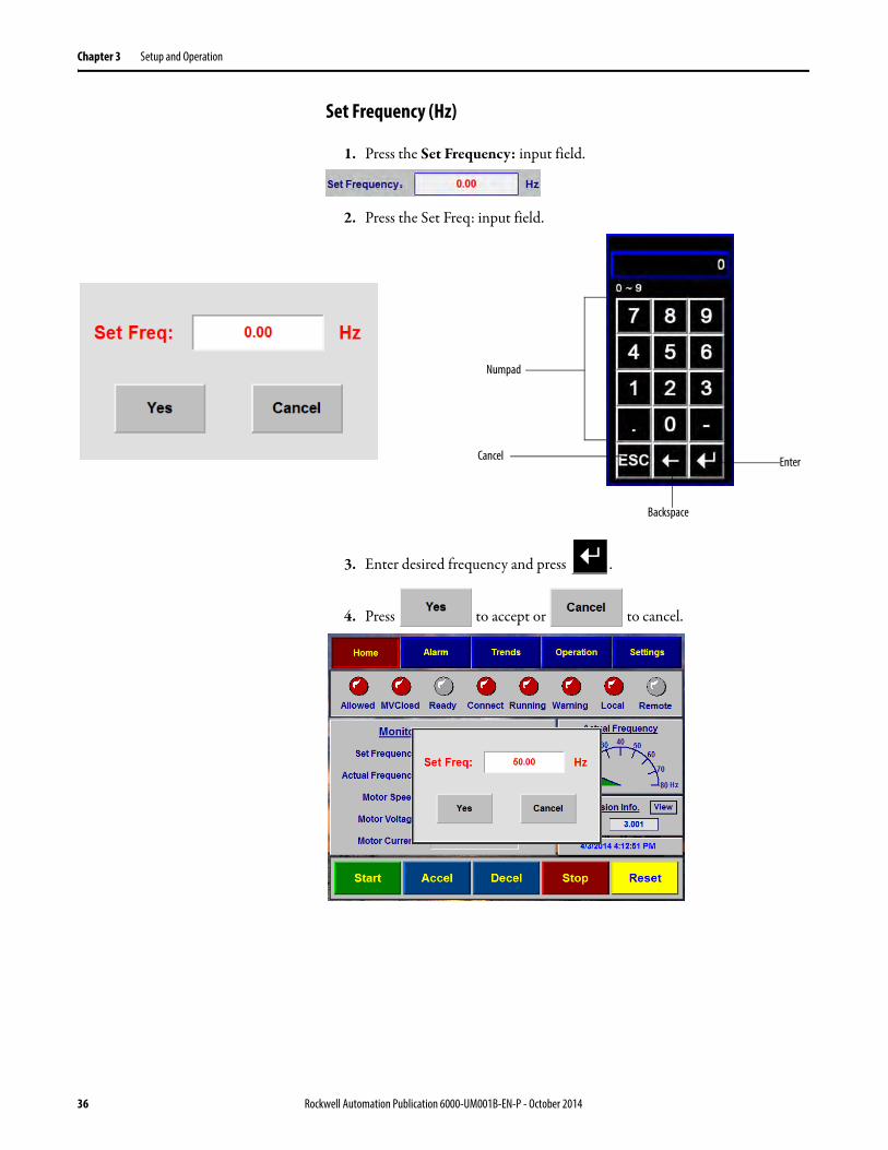
Set Frequency (Hz)
1. Press the Set Frequency: input field.
2. Press the Set Freq: input field.
3. Enter desired frequency and press .
4. Press to accept or to cancel.
Numpad
Cancel
Backspace
Enter
36 Rockwell Automation Publication 6000-UM001B-EN-P - October 2014
Setup and Operation Chapter 3
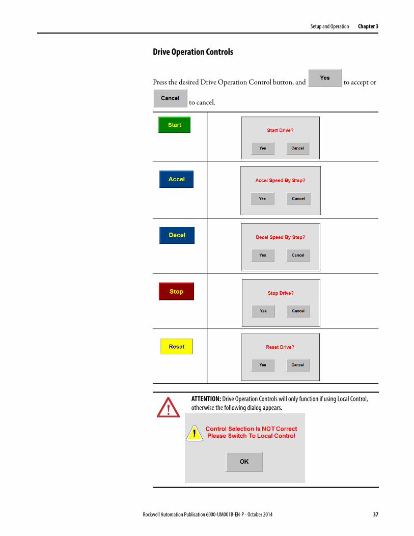
Drive Operation Controls
Press the desired Drive Operation Control button, and to accept or
to cancel.
ATTENTION: Drive Operation Controls will only function if using Local Control, otherwise the following dialog appears.
Rockwell Automation Publication 6000-UM001B-EN-P - October 2014 37

Chapter 3 Setup and Operation
View Version Information
Press under Version Info. to view the currently installed Firmware.
The Version Information screen shows the most current firmware installed for the applicable devices.
Will alwaysappear blue
The number ofPower Modules in
the drive willappear as blue; therest appear as grey
Fields show thefirmware version,where applicable
38 Rockwell Automation Publication 6000-UM001B-EN-P - October 2014

Setup and Operation Chapter 3
AlarmIf the drive encounters and alarm or warnings, will blink, indicating an active alarm.
Press the button in the Top Menu Bar to see the active alarms.
Active Alarms Controls
Reset Status
will reset just the quantity and accumulated time of the alarms. This
function does not reset the drive.
List of ActiveAlarms
Alarm Code
Quantity
Accumulated Time
Alarm
Code Alarm code. Codes beginning with W indicates a warning, codes beginning with F indicates a fault.
QTY How many times the alarm has occurred
Acc Time Time which has elapsed since the alarm
Message Description of the warning or fault
Reset Status Scroll to Top or Bottom of List
Scroll Alarm by Entry
Page Up/Page Down
Shows Alarm History
Rockwell Automation Publication 6000-UM001B-EN-P - October 2014 39

Chapter 3 Setup and Operation
Alarm History
Press to see a detailed listed of all warnings and faults on the drive.
The controls to scroll through the alarms are the same.
Sort Alarms
Press once to sort once to sort by time. Press again to sort by message.
TIP Current alarms appear as red; past alarms appear as gray.
40 Rockwell Automation Publication 6000-UM001B-EN-P - October 2014
Setup and Operation Chapter 3
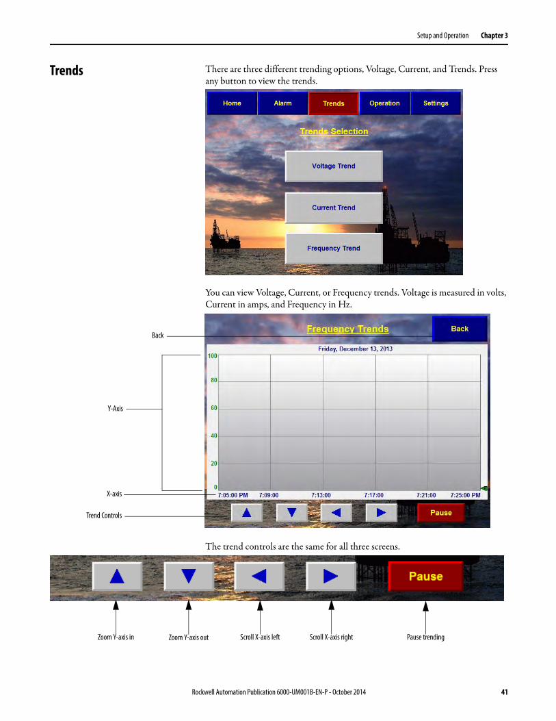
Trends There are three different trending options, Voltage, Current, and Trends. Press any button to view the trends.
You can view Voltage, Current, or Frequency trends. Voltage is measured in volts, Current in amps, and Frequency in Hz.
The trend controls are the same for all three screens.
Back
Y-Axis
X-axis
Trend Controls
Zoom Y-axis in Zoom Y-axis out Scroll X-axis left Scroll X-axis right Pause trending
Rockwell Automation Publication 6000-UM001B-EN-P - October 2014 41

Chapter 3 Setup and Operation
View Voltage, Current or Frequency Trends
1. From the Main Interface screen, press .
2. Press , , or
in the Trends Selection screen.
3. Use the and buttons to zoom in or out.
Press the and buttons to scroll.
4. Press to pause the trend capture.
5. Press to return to the Trends Selection screen.
TIP The time shown in the X-axis captures 20 minutes. Scrolling left or right will scroll in 10 minute increments.
42 Rockwell Automation Publication 6000-UM001B-EN-P - October 2014
Setup and Operation Chapter 3
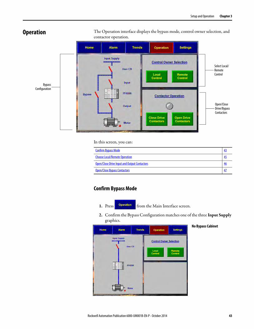
Operation The Operation interface displays the bypass mode, control owner selection, and contactor operation.
In this screen, you can:
Confirm Bypass Mode
1. Press from the Main Interface screen.
2. Confirm the Bypass Configuration matches one of the three Input Supply graphics.
BypassConfiguration
Select Local/Remote Control
Open/Close Drive/Bypass Contactors
Confirm Bypass Mode 43
Choose Local/Remote Operation 45
Open/Close Drive Input and Output Contactors 46
Open/Close Bypass Contactors 47
No Bypass Cabinet
Rockwell Automation Publication 6000-UM001B-EN-P - October 2014 43

Chapter 3 Setup and Operation
3. To change the Bypass Mode:
a. Press .
b. Press .
c. Choose desired Bypass Mode under Select Bypass Mode.
d. Press .
e. Press to confirm operation.
Manual Bypass Cabinet
Automatic Bypass Cabinet
Note the Contactor Operation selection appears when Automatic Bypass is selected
44 Rockwell Automation Publication 6000-UM001B-EN-P - October 2014

Setup and Operation Chapter 3
Choose Local/Remote Operation
1. Press from the Main Interface screen.
2. Under Control Owner Selection, press either or
.
3. Select to confirm in the Select Local Control? or Select Remote Control? dialog box.
ATTENTION: This operation can only operate while drive is not running.
Rockwell Automation Publication 6000-UM001B-EN-P - October 2014 45

Chapter 3 Setup and Operation
Open/Close Drive Input and Output Contactors
1. Under Contactor Operation, press either or .
2. Select to confirm in the Close Drive Input & Output Contactors? or Open Drive Input & Output Contactors? dialog box.
IMPORTANT Turn the 3-position on the selector switch on the front of the LV Cabinet to the Drive position.
ATTENTION: Operations in this graphic can only operate while on local control.
ATTENTION: This operation can only operate while drive is not running.
46 Rockwell Automation Publication 6000-UM001B-EN-P - October 2014

Setup and Operation Chapter 3
Open/Close Bypass Contactors
1. Under Contactor Operation, press either or .
2. Select to confirm in the Close Bypass Contactors? or Open Bypass Contactors? dialog box.
IMPORTANT Turn the 3-position on the selector switch on the front of the LV Cabinet to the Bypass position.
ATTENTION: Operations in this graphic can only operate while on local control.
ATTENTION: This operation can only operate while drive is not running.
Rockwell Automation Publication 6000-UM001B-EN-P - October 2014 47
Chapter 3 Setup and Operation
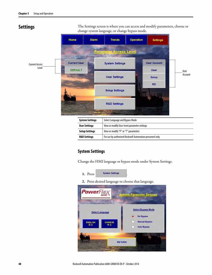
Settings The Settings screen is where you can access and modify parameters, choose or change system language, or change bypass mode.
System Settings
Change the HMI language or bypass mode under System Settings.
1. Press .
2. Press desired language to choose that language.
Current AccessLevel
User Account
System Settings Select Language and Bypass Mode
User Settings View or modify User-level parameter settings
Setup Settings View or modify “P” or “T” parameters
R&D Settings For use by authorized Rockwell Automation personnel only.
48 Rockwell Automation Publication 6000-UM001B-EN-P - October 2014

Setup and Operation Chapter 3
3. Select bypass mode and press to accept or to cancel.
4. Press to accept.
ATTENTION: Operations in this graphic can only operate while on local control.
ATTENTION: This operation can only be performed when any switch is closed.
Rockwell Automation Publication 6000-UM001B-EN-P - October 2014 49
Chapter 3 Setup and Operation
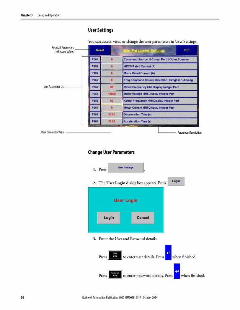
User Settings
You can access, view, or change the user parameters in User Settings.
Change User Parameters
1. Press .
2. The User Login dialog box appears. Press .
3. Enter the User and Password details.
Press to enter user details. Press when finished.
Press to enter password details. Press when finished.
User Parameter List
User Parameter Value
Reset all Parametersto Factory Values
Parameter Description
50 Rockwell Automation Publication 6000-UM001B-EN-P - October 2014

Setup and Operation Chapter 3
4. Press to login.
5. If the login was successful, the Current User will show as User.
6. Press .
In the User Parameters Settings screen, the user parameters automatically refresh.
Press the parameter input field to change the parameter value.
IMPORTANT If the login information was incorrect, you will be prompted to login again.
Numpad
Cancel
Backspace
Enter
Rockwell Automation Publication 6000-UM001B-EN-P - October 2014 51

Chapter 3 Setup and Operation
Press to restore all user parameters to the factory setting.
Press to return to the Parameter Access Level screen.
ATTENTION: Operations in this graphic can only operate while on local control.
ATTENTION: This operation can only operate while drive is not running.
TIP User parameter access will logout when you exit User Settings.
52 Rockwell Automation Publication 6000-UM001B-EN-P - October 2014

Setup and Operation Chapter 3
Setup Settings
View or modify “P” or “T” Parameters in the Setup Settings interface.
View/Change P or T Parameters
1. Press under Parameter Access Level.
The Setup Login dialog box appears. Press .
2. Enter the User and Password details.
Page Up
Page Down
ParameterNumber
ParameterField
Select a Parameternumber to see the
description here
Reset ParameterValues
IMPORTANT You must have Setup login access to view or modify “P” or “T” parameters.
Rockwell Automation Publication 6000-UM001B-EN-P - October 2014 53

Chapter 3 Setup and Operation
Press to enter user details. Press when finished.
Press to enter password details. Press when finished.
3. Press to login.
The Current User will now display Setup, indicating appropriate access has been granted.
4. Once logged in, press to proceed.
5. Press or in the Setup Parameter Type.
6. Press the Parameter Field and enter desired value on the keypad dialog and
press .
7. Press or to Page Up or Page Down through the parameters.
IMPORTANT If the login information was incorrect, you will be prompted to login again.
54 Rockwell Automation Publication 6000-UM001B-EN-P - October 2014

Setup and Operation Chapter 3
Restore “P” or “T” Parameters
Press to restore the parameters to factory settings.
Press to accept or to cancel.
ATTENTION: Operations in this graphic can only operate while on local control.
ATTENTION: This operation can only operate while drive is not running.
Rockwell Automation Publication 6000-UM001B-EN-P - October 2014 55

Chapter 3 Setup and Operation
Notes:
56 Rockwell Automation Publication 6000-UM001B-EN-P - October 2014
Chapter 4
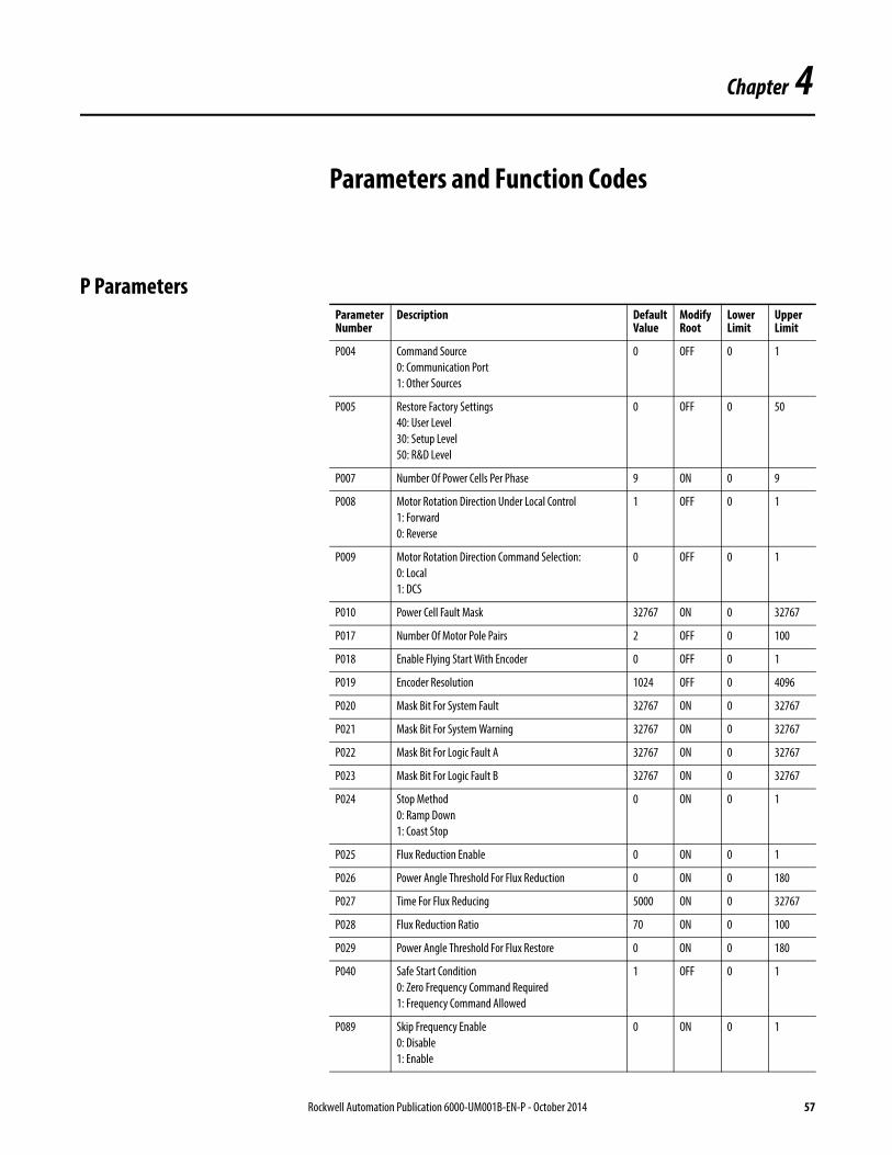
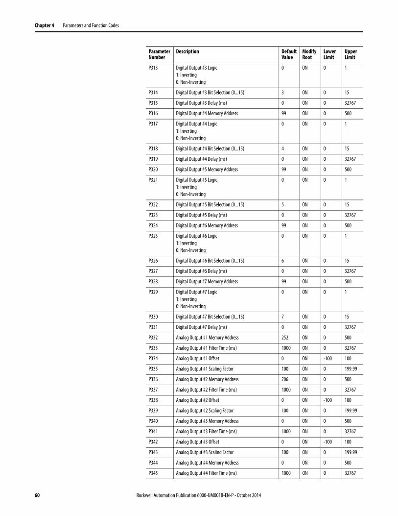
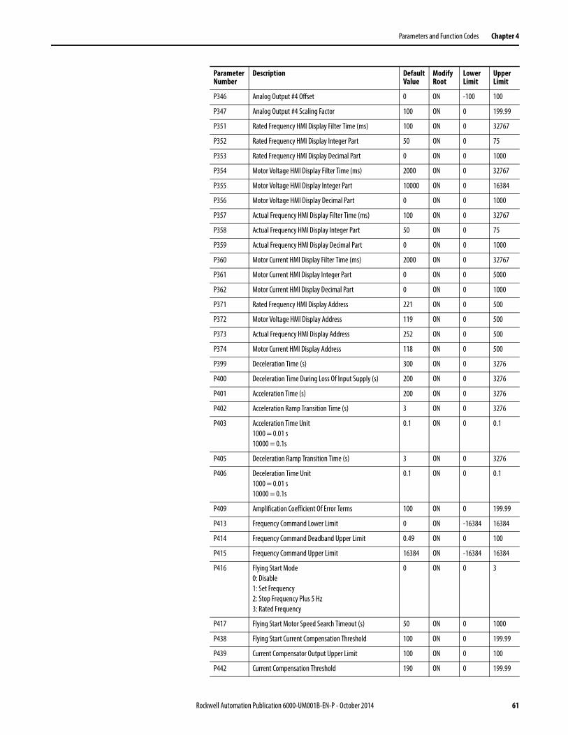
Parameters and Function Codes
P ParametersParameter Number
Description Default Value
Modify Root
Lower Limit
Upper Limit
P004 Command Source0: Communication Port1: Other Sources
0 OFF 0 1
P005 Restore Factory Settings40: User Level30: Setup Level50: R&D Level
0 OFF 0 50
P007 Number Of Power Cells Per Phase 9 ON 0 9
P008 Motor Rotation Direction Under Local Control1: Forward0: Reverse
1 OFF 0 1
P009 Motor Rotation Direction Command Selection:0: Local1: DCS
0 OFF 0 1
P010 Power Cell Fault Mask 32767 ON 0 32767
P017 Number Of Motor Pole Pairs 2 OFF 0 100
P018 Enable Flying Start With Encoder 0 OFF 0 1
P019 Encoder Resolution 1024 OFF 0 4096
P020 Mask Bit For System Fault 32767 ON 0 32767
P021 Mask Bit For System Warning 32767 ON 0 32767
P022 Mask Bit For Logic Fault A 32767 ON 0 32767
P023 Mask Bit For Logic Fault B 32767 ON 0 32767
P024 Stop Method0: Ramp Down1: Coast Stop
0 ON 0 1
P025 Flux Reduction Enable 0 ON 0 1
P026 Power Angle Threshold For Flux Reduction 0 ON 0 180
P027 Time For Flux Reducing 5000 ON 0 32767
P028 Flux Reduction Ratio 70 ON 0 100
P029 Power Angle Threshold For Flux Restore 0 ON 0 180
P040 Safe Start Condition0: Zero Frequency Command Required1: Frequency Command Allowed
1 OFF 0 1
P089 Skip Frequency Enable0: Disable1: Enable
0 ON 0 1
Rockwell Automation Publication 6000-UM001B-EN-P - October 2014 57

Chapter 4 Parameters and Function Codes
P090 Skip Frequency 1 Lower Limit 0 ON 0 75
P091 Skip Frequency 1 Upper Limit 0 ON 0 75
P092 Skip Frequency 2 Lower Limit 0 ON 0 75
P093 Skip Frequency 2 Upper Limit 0 ON 0 75
P113 Flying Start-Initial Output Voltage Percentage (%) 5 ON 0 100
P114 Flying Start-Current Comparison Delay For Motor Speed Search (ms)
1000 ON 0 5000
P115 Flying Start-Current Threshold For Successful Motor Speed Search
5 ON 0 100
P198 HECS Rated Current (A) 0 ON 0 5000
P199 Motor Rated Current (A) 0 ON 0 5000
P200 Ia Motor Current Memory Address 13 ON 0 500
P201 Motor Ia Scaling Correction Factor 100 ON 0 199.99
P202 Ib Motor Current Memory Address 14 ON 0 500
P203 Motor Ib Scaling Correction Factor 100 ON 0 199.99
P204 Motor Uab Voltage Address 11 ON 0 500
P205 Motor Uab Voltage Scaling Factor Correction 199.99 ON 0 199.99
P206 Motor Uac Voltage Scaling Factor Correction 199.99 ON 0 199.99
P211 Filter Time For Abnormal Output Voltage (ms) 1000 ON 0 32767
P212 Filter Time For Output Short-Circuit (ms) 10 ON 0 32767
P213 Output Short-Circuit Fault Threshold 180 ON 0 199.99
P214 Over Current Low/High Speed Region Boundary 5 ON 0 100
P215 Filter Time For Output Over Current (0.1 s) 200 ON 0 32767
P216 High-Frequency Output Over Current Threshold 120 ON 0 199.99
P217 Low-Frequency Output Over Current Threshold 70 ON 0 199.99
P218 Filter Time For Motor Over Temperature (0.1 s) 6000 ON 0 32767
P219 Motor Over Temperature Warning Threshold 110 ON 0 199.99
P220 Motor Over Temperature Fault Threshold 120 ON 0 199.99
P221 Filter Time For Output Over Voltage (ms) 100 ON 0 32767
P222 Output Over Voltage Fault Threshold 130 ON 0 199.99
P223 Output Voltage Deviation Warning Threshold 60 ON 0 199.99
P224 Output Voltage Deviation Fault Threshold 80 ON 0 199.99
P225 Motor Over Temperature Warning Cancellation Temperature
100 ON 0 199.99
P226 Output Voltage Abnormality Warning Cancellation Threshold
50 ON 0 199.99
P227 Ground Fault Detection Scaling Correction Factor 100 ON 0 199.99
P228 Filter Time For Ground Fault (ms) 1000 ON 0 32767
P229 Ground Fault Warning Threshold 20 ON 0 199.99
P230 Ground Fault Trip Threshold 60 ON 0 199.99
P231 Filter Time For Overspeed Fault (Upper Limit) 100 ON 0 32767
Parameter Number
Description Default Value
Modify Root
Lower Limit
Upper Limit
58 Rockwell Automation Publication 6000-UM001B-EN-P - October 2014

Parameters and Function Codes Chapter 4
P232 Filter Time For Overspeed Fault (Lower Limit) 100 ON 0 32767
P233 Threshold Of Over-Speed Fault At Lower Frequency Limit 20 ON 0 199.99
P234 Threshold Of Over-Speed Fault At Upper Frequency Limit 20 ON 0 199.99
P235 Frequency Deviation Warning Cancellation Threshold 0.99 ON 0 199.99
P236 Frequency Deviation Warning Threshold 6 ON 0 199.99
P237 Frequency Deviation Warning Delay (ms) 8 ON 0 32767
P238 Motor Stall Fault Threshold 10 ON 0 199.99
P239 Motor Stall Fault Delay (ms) 6000 ON 0 32767
P240 Transformer Over Temperature Fault Delay (ms) 5000 ON 0 32767
P241 Transformer Over Temperature Warning Delay (ms) 5000 ON 0 32767
P247 Software Interlock: 1-Disable, 0-Enable 1 ON 0 1
P250 Input Contactor/Circuit Breaker Close Delay (ms) 5000 ON 0 10000
P251 Frequency Command-Low Frequency Region Boundary 0.5 ON 0 100
P252 Motor In Stopping Condition Threshold 1 ON 0 100
P253 Motor Coast Stop Time 10 ON 0 10000
P256 Ground Fault Warning Cancellation Threshold 10 ON 0 199.99
P257 Motor Stall Warning Cancellation Threshold 2.98 ON 0 199.99
P259 Frequency Command Analog Offset 0 ON -100 199.99
P260 Frequency Command Analog Scaling Factor 100 ON 0 199.99
P261 Frequency Command Analog Minimum 0.49 ON 0 199.99
P262 Frequency Command Source Selection: 0-Digital, 1-Analog
0 OFF 0 1
P270 Delayed Lockout Time Of Stop Operation (ms) 2000 ON 0 5000
P271 Flux Delay (ms) 50 ON 0 5000
P300 Digital Output #0 Memory Address 99 ON 0 500
P301 Digital Output #0 Logic: 1-Inverting, 0-Non-Inverting 0 ON 0 1
P302 Digital Output #0 Bit Selection (0...15) 0 ON 0 15
P303 Digital Output #0 Delay (ms) 0 ON 0 32767
P304 Digital Output #1 Memory Address 99 ON 0 500
P305 Digital Output #1 Logic: 1-Inverting, 0-Non-Inverting 0 ON 0 1
P306 Digital Output #1 Bit Selection (0...15) 1 ON 0 15
P307 Digital Output #1 Delay (ms) 0 ON 0 32767
P308 Digital Output #2 Memory Address 99 ON 0 500
P309 Digital Output #2 Logic1: Inverting0: Non-Inverting
0 ON 0 1
P310 Digital Output #2 Bit Selection (0...15) 2 ON 0 15
P311 Digital Output #2 Delay (ms) 0 ON 0 32767
P312 Digital Output #3 Memory Address 99 ON 0 500
Parameter Number
Description Default Value
Modify Root
Lower Limit
Upper Limit
Rockwell Automation Publication 6000-UM001B-EN-P - October 2014 59
Chapter 4 Parameters and Function Codes
P313 Digital Output #3 Logic1: Inverting0: Non-Inverting
0 ON 0 1
P314 Digital Output #3 Bit Selection (0...15) 3 ON 0 15
P315 Digital Output #3 Delay (ms) 0 ON 0 32767
P316 Digital Output #4 Memory Address 99 ON 0 500
P317 Digital Output #4 Logic1: Inverting0: Non-Inverting
0 ON 0 1
P318 Digital Output #4 Bit Selection (0...15) 4 ON 0 15
P319 Digital Output #4 Delay (ms) 0 ON 0 32767
P320 Digital Output #5 Memory Address 99 ON 0 500
P321 Digital Output #5 Logic1: Inverting0: Non-Inverting
0 ON 0 1
P322 Digital Output #5 Bit Selection (0...15) 5 ON 0 15
P323 Digital Output #5 Delay (ms) 0 ON 0 32767
P324 Digital Output #6 Memory Address 99 ON 0 500
P325 Digital Output #6 Logic1: Inverting0: Non-Inverting
0 ON 0 1
P326 Digital Output #6 Bit Selection (0...15) 6 ON 0 15
P327 Digital Output #6 Delay (ms) 0 ON 0 32767
P328 Digital Output #7 Memory Address 99 ON 0 500
P329 Digital Output #7 Logic1: Inverting0: Non-Inverting
0 ON 0 1
P330 Digital Output #7 Bit Selection (0...15) 7 ON 0 15
P331 Digital Output #7 Delay (ms) 0 ON 0 32767
P332 Analog Output #1 Memory Address 252 ON 0 500
P333 Analog Output #1 Filter Time (ms) 1000 ON 0 32767
P334 Analog Output #1 Offset 0 ON -100 100
P335 Analog Output #1 Scaling Factor 100 ON 0 199.99
P336 Analog Output #2 Memory Address 206 ON 0 500
P337 Analog Output #2 Filter Time (ms) 1000 ON 0 32767
P338 Analog Output #2 Offset 0 ON -100 100
P339 Analog Output #2 Scaling Factor 100 ON 0 199.99
P340 Analog Output #3 Memory Address 0 ON 0 500
P341 Analog Output #3 Filter Time (ms) 1000 ON 0 32767
P342 Analog Output #3 Offset 0 ON -100 100
P343 Analog Output #3 Scaling Factor 100 ON 0 199.99
P344 Analog Output #4 Memory Address 0 ON 0 500
P345 Analog Output #4 Filter Time (ms) 1000 ON 0 32767
Parameter Number
Description Default Value
Modify Root
Lower Limit
Upper Limit
60 Rockwell Automation Publication 6000-UM001B-EN-P - October 2014
Parameters and Function Codes Chapter 4
P346 Analog Output #4 Offset 0 ON -100 100
P347 Analog Output #4 Scaling Factor 100 ON 0 199.99
P351 Rated Frequency HMI Display Filter Time (ms) 100 ON 0 32767
P352 Rated Frequency HMI Display Integer Part 50 ON 0 75
P353 Rated Frequency HMI Display Decimal Part 0 ON 0 1000
P354 Motor Voltage HMI Display Filter Time (ms) 2000 ON 0 32767
P355 Motor Voltage HMI Display Integer Part 10000 ON 0 16384
P356 Motor Voltage HMI Display Decimal Part 0 ON 0 1000
P357 Actual Frequency HMI Display Filter Time (ms) 100 ON 0 32767
P358 Actual Frequency HMI Display Integer Part 50 ON 0 75
P359 Actual Frequency HMI Display Decimal Part 0 ON 0 1000
P360 Motor Current HMI Display Filter Time (ms) 2000 ON 0 32767
P361 Motor Current HMI Display Integer Part 0 ON 0 5000
P362 Motor Current HMI Display Decimal Part 0 ON 0 1000
P371 Rated Frequency HMI Display Address 221 ON 0 500
P372 Motor Voltage HMI Display Address 119 ON 0 500
P373 Actual Frequency HMI Display Address 252 ON 0 500
P374 Motor Current HMI Display Address 118 ON 0 500
P399 Deceleration Time (s) 300 ON 0 3276
P400 Deceleration Time During Loss Of Input Supply (s) 200 ON 0 3276
P401 Acceleration Time (s) 200 ON 0 3276
P402 Acceleration Ramp Transition Time (s) 3 ON 0 3276
P403 Acceleration Time Unit1000 = 0.01 s10000 = 0.1s
0.1 ON 0 0.1
P405 Deceleration Ramp Transition Time (s) 3 ON 0 3276
P406 Deceleration Time Unit1000 = 0.01 s10000 = 0.1s
0.1 ON 0 0.1
P409 Amplification Coefficient Of Error Terms 100 ON 0 199.99
P413 Frequency Command Lower Limit 0 ON -16384 16384
P414 Frequency Command Deadband Upper Limit 0.49 ON 0 100
P415 Frequency Command Upper Limit 16384 ON -16384 16384
P416 Flying Start Mode0: Disable1: Set Frequency2: Stop Frequency Plus 5 Hz3: Rated Frequency
0 ON 0 3
P417 Flying Start Motor Speed Search Timeout (s) 50 ON 0 1000
P438 Flying Start Current Compensation Threshold 100 ON 0 199.99
P439 Current Compensator Output Upper Limit 100 ON 0 100
P442 Current Compensation Threshold 190 ON 0 199.99
Parameter Number
Description Default Value
Modify Root
Lower Limit
Upper Limit
Rockwell Automation Publication 6000-UM001B-EN-P - October 2014 61

Chapter 4 Parameters and Function Codes
P443 Upper Limit Of Current Compensation Input Deadband 0 ON -16384 32767
P444 Lower Limit Of Current Compensation Input Deadband 0 ON -16384 32767
P445 Proportional Coefficient Of Current Compensation (%) 5 ON 0 199.99
P446 Integral Coefficient Of Current Compensation (ms) 100 ON 0 32767
P447 Lower Limit Of Current Compensation Output -100 ON -100 0
P448 Minimum Frequency For Current Compensation 5 ON 0 100
P449 Proportional Coefficient Of Current Compensation Output (%)
0.99 ON 0 199.99
P450 Upper Limit Of Frequency Compensation Output 100 ON 0 100
P451 Low Speed Voltage Compensation (%) 0.99 OFF 0 10
P452 Low Speed Voltage Compensation Frequency Threshold 20 ON 0 100
P453 V/F Curve0: Linear1: Parabolic Curve2: Predefined Curve #13: Predefined Curve #2
1 OFF 0 3
P454 Flux Time (s) 0.5 OFF 0 10
P455 Modulation Index 87.99 ON 0 199.99
P456 Motor Voltage Upper Limit 87.99 ON 0 199.99
P457 Flying Start Voltage Recovery Time (s) (Low Speed Region)
5 ON 0 163.84
P458 Coefficient A 40 OFF 0 100
P459 Flying Start Voltage Recovery Time (s) (High Speed Region)
5 ON 0 163.84
P460 Rated Output Frequency 50 OFF 0 75
P461 Restart Enable 0 ON 0 1
P462 Fault Reset Timeout (s) 120 ON 0 120
P463 Flying Start Low/High Speed Regions Boundary (%) 16 ON 0 100
P465 Power Cell Fault Auto Reset Delay (s) 4 ON 0 10
P466 Maximum Output Frequency 50 OFF 0 75
P467 Over Speed Enable 0 OFF 0 1
P470 Version Compatibility Enable 1 OFF 0 1
P497 Major Rev # Of DSP Main Firmware 0 CannotModify
—— ——
P498 Minor Rev # Of DSP Main Firmware 2 CannotModify
—— ——
P499 Display Fault Masks Button 0 ON 0 1
P500 Display DSP Variables 0 ON 0 1
Parameter Number
Description Default Value
Modify Root
Lower Limit
Upper Limit
62 Rockwell Automation Publication 6000-UM001B-EN-P - October 2014

Parameters and Function Codes Chapter 4
T Parameters Parameter Number
Description Default Value
Modify Root
Lower Limit
Upper Limit
T01 Fault-To-Bypass0: Disable1: Enable
0 ON 0 1
T02 Fault-To-Bypass Delay 3 ON 0 60
T03 Fault-To-Bypass Delay When Starting the Motor (0...60s)
60 ON 0 60
T04 Fault-To-Bypass Minimum Frequency0...Rated Frequency (Hz)
5 ON 0 Rated Frequency
T05 Auto Restart After Input Supply Power Loss0: Disable1: Enable
0 ON 0 1
T06 Input Supply Power Loss Time forAuto Restart (0...20s)
20 ON 0 20
T07 Local Frequency Command Selection0: Digital1: Analog
0 ON 0 1
T08 Remote Frequency Command Selection1: Analog2: 4-Step Speed4: Communication Port
1 ON 1 4
T09 Frequency Step For Accel or Decel 1 ON 1 Rated Frequency
T10 Exit Config Environment Password 555 OFF
T11 Automatic Bypass-To-Drive or Drive-To-Bypass Selection
T12 PID Parameter Settings
P 0.01 ON 0 32767
I 0.01 ON 0 32767
D 0 ON 0 32767
D Gain 0 ON 0 32767
T13 4-Step Variable Speed(available only when T8=2)
Speed 1 10 ON 0 Rated Frequency
Speed 2 20 ON 0 Rated Frequency
Speed 3 30 ON 0 Rated Frequency
Speed 4 40 ON 0 Rated Frequency
Rockwell Automation Publication 6000-UM001B-EN-P - October 2014 63

Chapter 4 Parameters and Function Codes
Alarm ListCode Alarm
F0000 IGBT Set #1 Over Current In Power Cell #1
F0001 IGBT Set #2 Over Current In Power Cell #1
F0002 Input Over Voltage In Power Cell #1
F0004 Communication Error In Power Cell #1
F0005 No PWM1 Pulse For IGBT Set #1 In Power Cell #1
F0006 No PWM2 Pulse For IGBT Set #2 In Power Cell #1
F0007 IGBT Set #1 Failed To Turn On In Power Cell #1
F0008 IGBT Set #2 Failed To Turn On In Power Cell #1
F0009 Power Cell #1 Bypassed
F0010 Over Temperature In Power Cell #1
F0011 Power Cell #1 Failed To Bypass
F0012 One Phase Lost In Power Cell #1
F0013 Two Phases Lost In Power Cell #1
F0100 IGBT Set #1 Over Current In Power Cell #2
F0101 IGBT Set #2 Over Current In Power Cell #2
F0102 Input Over Voltage In Power Cell #2
F0104 Communication Error In Power Cell #2
F0105 No PWM1 Pulse For IGBT Set #1 In Power Cell #2
F0106 No PWM2 Pulse For IGBT Set #2 In Power Cell #2
F0107 IGBT Set #1 Failed To Turn On In Power Cell #2
F0108 IGBT Set #2 Failed To Turn On In Power Cell #2
F0109 Power Cell #2 Bypassed
F0110 Over Temperature In Power Cell #2
F0111 Power Cell #2 Failed To Bypass
F0112 One Phase Lost In Power Cell #2
F0113 Two Phases Lost In Power Cell #2
F0200 IGBT Set #1 Over Current In Power Cell #3
F0201 IGBT Set #2 Over Current In Power Cell #3
F0202 Input Over Voltage In Power Cell #3
F0204 Communication Error In Power Cell #3
F0205 No PWM1 Pulse For IGBT Set #1 In Power Cell #3
F0206 No PWM2 Pulse For IGBT Set #2 In Power Cell #3
F0207 IGBT Set #1 Failed To Turn On In Power Cell #3
F0208 IGBT Set #2 Failed To Turn On In Power Cell #3
F0209 Power Cell #3 Bypassed
F0210 Over Temperature In Power Cell #3
F0211 Power Cell #3 Failed To Bypass
F0212 One Phase Lost In Power Cell #3
F0213 Two Phases Lost In Power Cell #3
64 Rockwell Automation Publication 6000-UM001B-EN-P - October 2014

Parameters and Function Codes Chapter 4
F0300 IGBT Set #1 Over Current In Power Cell #4
F0301 IGBT Set #2 Over Current In Power Cell #4
F0302 Input Over Voltage In Power Cell #4
F0304 Communication Error In Power Cell #4
F0305 No PWM1 Pulse For IGBT Set #1 In Power Cell #4
F0306 No PWM2 Pulse For IGBT Set #2 In Power Cell #4
F0307 IGBT Set #1 Failed To Turn On In Power Cell #4
F0308 IGBT Set #2 Failed To Turn On In Power Cell #4
F0309 Power Cell #4 Bypassed
F0310 Over Temperature In Power Cell #4
F0311 Power Cell #4 Failed To Bypass
F0312 One Phase Lost In Power Cell #4
F0313 Two Phases Lost In Power Cell #4
F0400 IGBT Set #1 Over Current In Power Cell #5
F0401 IGBT Set #2 Over Current In Power Cell #5
F0402 Input Over Voltage In Power Cell #5
F0404 Communication Error In Power Cell #5
F0405 No PWM1 Pulse For IGBT Set #1 In Power Cell #5
F0406 No PWM2 Pulse For IGBT Set #2 In Power Cell #5
F0407 IGBT Set #1 Failed To Turn On In Power Cell #5
F0408 IGBT Set #2 Failed To Turn On In Power Cell #5
F0409 Power Cell #5 Bypassed
F0410 Over Temperature In Power Cell #5
F0411 Power Cell #5 Failed To Bypass
F0412 One Phase Lost In Power Cell #5
F0413 Two Phases Lost In Power Cell #5
F0500 IGBT Set #1 Over Current In Power Cell #6
F0501 IGBT Set #2 Over Current In Power Cell #6
F0502 Input Over Voltage In Power Cell #6
F0504 Communication Error In Power Cell #6
F0505 No PWM1 Pulse For IGBT Set #1 In Power Cell #6
F0506 No PWM2 Pulse For IGBT Set #2 In Power Cell #6
F0507 IGBT Set #1 Failed To Turn On In Power Cell #6
F0508 IGBT Set #2 Failed To Turn On In Power Cell #6
F0509 Power Cell #6 Bypassed
F0510 Over Temperature In Power Cell #6
F0511 Power Cell #6 Failed To Bypass
F0512 One Phase Lost In Power Cell #6
F0513 Two Phases Lost In Power Cell #6
F0600 IGBT Set #1 Over Current In Power Cell #7
Code Alarm
Rockwell Automation Publication 6000-UM001B-EN-P - October 2014 65

Chapter 4 Parameters and Function Codes
F0601 IGBT Set #2 Over Current In Power Cell #7
F0602 Input Over Voltage In Power Cell #7
F0604 Communication Error In Power Cell #7
F0605 No PWM1 Pulse For IGBT Set #1 In Power Cell #7
F0606 No PWM2 Pulse For IGBT Set #2 In Power Cell #7
F0607 IGBT Set #1 Failed To Turn On In Power Cell #7
F0608 IGBT Set #2 Failed To Turn On In Power Cell #7
F0609 Power Cell #7 Bypassed
F0610 Over Temperature In Power Cell #7
F0611 Power Cell #7 Failed To Bypass
F0612 One Phase Lost In Power Cell #7
F0613 Two Phases Lost In Power Cell #7
F0700 IGBT Set #1 Over Current In Power Cell #8
F0701 IGBT Set #2 Over Current In Power Cell #8
F0702 Input Over Voltage In Power Cell #8
F0704 Communication Error In Power Cell #8
F0705 No PWM1 Pulse For IGBT Set #1 In Power Cell #8
F0706 No PWM2 Pulse For IGBT Set #2 In Power Cell #8
F0707 IGBT Set #1 Failed To Turn On In Power Cell #8
F0708 IGBT Set #2 Failed To Turn On In Power Cell #8
F0709 Power Cell #8 Bypassed
F0710 Over Temperature In Power Cell #8
F0711 Power Cell #8 Failed To Bypass
F0712 One Phase Lost In Power Cell #8
F0713 Two Phases Lost In Power Cell #8
F0800 IGBT Set #1 Over Current In Power Cell #9
F0801 IGBT Set #2 Over Current In Power Cell #9
F0802 Input Over Voltage In Power Cell #9
F0804 Communication Error In Power Cell #9
F0805 No PWM1 Pulse For IGBT Set #1 In Power Cell #9
F0806 No PWM2 Pulse For IGBT Set #2 In Power Cell #9
F0807 IGBT Set #1 Failed To Turn On In Power Cell #9
F0808 IGBT Set #2 Failed To Turn On In Power Cell #9
F0809 Power Cell #9 Bypassed
F0810 Over Temperature In Power Cell #9
F0811 Power Cell #9 Failed To Bypass
F0812 One Phase Lost In Power Cell #9
F0813 Two Phases Lost In Power Cell #9
F0900 IGBT Set #1 Over Current In Power Cell #10
F0901 IGBT Set #2 Over Current In Power Cell #10
Code Alarm
66 Rockwell Automation Publication 6000-UM001B-EN-P - October 2014

Parameters and Function Codes Chapter 4
F0902 Input Over Voltage In Power Cell #10
F0904 Communication Error In Power Cell #10
F0905 No PWM1 Pulse For IGBT Set #1 In Power Cell #10
F0906 No PWM2 Pulse For IGBT Set #2 In Power Cell #10
F0907 IGBT Set #1 Failed To Turn On In Power Cell #10
F0908 IGBT Set #2 Failed To Turn On In Power Cell #10
F0909 Power Cell #10 Bypassed
F0910 Over Temperature In Power Cell #10
F0911 Power Cell #10 Failed To Bypass
F0912 One Phase Lost In Power Cell #10
F0913 Two Phases Lost In Power Cell #10
F1000 IGBT Set #1 Over Current In Power Cell #11
F1001 IGBT Set #2 Over Current In Power Cell #11
F1002 Input Over Voltage In Power Cell #11
F1004 Communication Error In Power Cell #11
F1005 No PWM1 Pulse For IGBT Set #1 In Power Cell #11
F1006 No PWM2 Pulse For IGBT Set #2 In Power Cell #11
F1007 IGBT Set #1 Failed To Turn On In Power Cell #11
F1008 IGBT Set #2 Failed To Turn On In Power Cell #11
F1009 Power Cell #11 Bypassed
F1010 Over Temperature In Power Cell #11
F1011 Power Cell #11 Failed To Bypass
F1012 One Phase Lost In Power Cell #11
F1013 Two Phases Lost In Power Cell #11
F1100 IGBT Set #1 Over Current In Power Cell #12
F1101 IGBT Set #2 Over Current In Power Cell #12
F1102 Input Over Voltage In Power Cell #12
F1104 Communication Error In Power Cell #12
F1105 No PWM1 Pulse For IGBT Set #1 In Power Cell #12
F1106 No PWM2 Pulse For IGBT Set #2 In Power Cell #12
F1107 IGBT Set #1 Failed To Turn On In Power Cell #12
F1108 IGBT Set #2 Failed To Turn On In Power Cell #12
F1109 Power Cell #12 Bypassed
F1110 Over Temperature In Power Cell #12
F1111 Power Cell #12 Failed To Bypass
F1112 One Phase Lost In Power Cell #12
F1113 Two Phases Lost In Power Cell #12
F1200 IGBT Set #1 Over Current In Power Cell #13
F1201 IGBT Set #2 Over Current In Power Cell #13
F1202 Input Over Voltage In Power Cell #13
Code Alarm
Rockwell Automation Publication 6000-UM001B-EN-P - October 2014 67

Chapter 4 Parameters and Function Codes
F1204 Communication Error In Power Cell #13
F1205 No PWM1 Pulse For IGBT Set #1 In Power Cell #13
F1206 No PWM2 Pulse For IGBT Set #2 In Power Cell #13
F1207 IGBT Set #1 Failed To Turn On In Power Cell #13
F1208 IGBT Set #2 Failed To Turn On In Power Cell #13
F1209 Power Cell #13 Bypassed
F1210 Over Temperature In Power Cell #13
F1211 Power Cell #13 Failed To Bypass
F1212 One Phase Lost In Power Cell #13
F1213 Two Phases Lost In Power Cell #13
F1300 IGBT Set #1 Over Current In Power Cell #14
F1301 IGBT Set #2 Over Current In Power Cell #14
F1302 Input Over Voltage In Power Cell #14
F1304 Communication Error In Power Cell #14
F1305 No PWM1 Pulse For IGBT Set #1 In Power Cell #14
F1306 No PWM2 Pulse For IGBT Set #2 In Power Cell #14
F1307 IGBT Set #1 Failed To Turn On In Power Cell #14
F1308 IGBT Set #2 Failed To Turn On In Power Cell #14
F1309 Power Cell #14 Bypassed
F1310 Over Temperature In Power Cell #14
F1311 Power Cell #14 Failed To Bypass
F1312 One Phase Lost In Power Cell #14
F1313 Two Phases Lost In Power Cell #14
F1400 IGBT Set #1 Over Current In Power Cell #15
F1401 IGBT Set #2 Over Current In Power Cell #15
F1402 Input Over Voltage In Power Cell #15
F1404 Communication Error In Power Cell #15
F1405 No PWM1 Pulse For IGBT Set #1 In Power Cell #15
F1406 No PWM2 Pulse For IGBT Set #2 In Power Cell #15
F1407 IGBT Set #1 Failed To Turn On In Power Cell #15
F1408 IGBT Set #2 Failed To Turn On In Power Cell #15
F1409 Power Cell #15 Bypassed
F1410 Over Temperature In Power Cell #15
F1411 Power Cell #15 Failed To Bypass
F1412 One Phase Lost In Power Cell #15
F1413 Two Phases Lost In Power Cell #15
F1500 IGBT Set #1 Over Current In Power Cell #16
F1501 IGBT Set #2 Over Current In Power Cell #16
F1502 Input Over Voltage In Power Cell #16
F1504 Communication Error In Power Cell #16
Code Alarm
68 Rockwell Automation Publication 6000-UM001B-EN-P - October 2014

Parameters and Function Codes Chapter 4
F1505 No PWM1 Pulse For IGBT Set #1 In Power Cell #16
F1506 No PWM2 Pulse For IGBT Set #2 In Power Cell #16
F1507 IGBT Set #1 Failed To Turn On In Power Cell #16
F1508 IGBT Set #2 Failed To Turn On In Power Cell #16
F1509 Power Cell #16 Bypassed
F1510 Over Temperature In Power Cell #16
F1511 Power Cell #16 Failed To Bypass
F1512 One Phase Lost In Power Cell #16
F1513 Two Phases Lost In Power Cell #16
F1600 IGBT Set #1 Over Current In Power Cell #17
F1601 IGBT Set #2 Over Current In Power Cell #17
F1602 Input Over Voltage In Power Cell #17
F1604 Communication Error In Power Cell #17
F1605 No PWM1 Pulse For IGBT Set #1 In Power Cell #17
F1606 No PWM2 Pulse For IGBT Set #2 In Power Cell #17
F1607 IGBT Set #1 Failed To Turn On In Power Cell #17
F1608 IGBT Set #2 Failed To Turn On In Power Cell #17
F1609 Power Cell #17 Bypassed
F1610 Over Temperature In Power Cell #17
F1611 Power Cell #17 Failed To Bypass
F1612 One Phase Lost In Power Cell #17
F1613 Two Phases Lost In Power Cell #17
F1700 IGBT Set #1 Over Current In Power Cell #18
F1701 IGBT Set #2 Over Current In Power Cell #18
F1702 Input Over Voltage In Power Cell #18
F1704 Communication Error In Power Cell #18
F1705 No PWM1 Pulse For IGBT Set #1 In Power Cell #18
F1706 No PWM2 Pulse For IGBT Set #2 In Power Cell #18
F1707 IGBT Set #1 Failed To Turn On In Power Cell #18
F1708 IGBT Set #2 Failed To Turn On In Power Cell #18
F1709 Power Cell #18 Bypassed
F1710 Over Temperature In Power Cell #18
F1711 Power Cell #18 Failed To Bypass
F1712 One Phase Lost In Power Cell #18
F1713 Two Phases Lost In Power Cell #18
F1800 IGBT Set #1 Over Current In Power Cell #19
F1801 IGBT Set #2 Over Current In Power Cell #19
F1802 Input Over Voltage In Power Cell #19
F1804 Communication Error In Power Cell #19
F1805 No PWM1 Pulse For IGBT Set #1 In Power Cell #19
Code Alarm
Rockwell Automation Publication 6000-UM001B-EN-P - October 2014 69

Chapter 4 Parameters and Function Codes
F1806 No PWM2 Pulse For IGBT Set #2 In Power Cell #19
F1807 IGBT Set #1 Failed To Turn On In Power Cell #19
F1808 IGBT Set #2 Failed To Turn On In Power Cell #19
F1809 Power Cell #19 Bypassed
F1810 Over Temperature In Power Cell #19
F1811 Power Cell #19 Failed To Bypass
F1812 One Phase Lost In Power Cell #19
F1813 Two Phases Lost In Power Cell #19
F1900 IGBT Set #1 Over Current In Power Cell #20
F1901 IGBT Set #2 Over Current In Power Cell #20
F1902 Input Over Voltage In Power Cell #20
F1904 Communication Error In Power Cell #20
F1905 No PWM1 Pulse For IGBT Set #1 In Power Cell #20
F1906 No PWM2 Pulse For IGBT Set #2 In Power Cell #20
F1907 IGBT Set #1 Failed To Turn On In Power Cell #20
F1908 IGBT Set #2 Failed To Turn On In Power Cell #20
F1909 Power Cell #20 Bypassed
F1910 Over Temperature In Power Cell #20
F1911 Power Cell #20 Failed To Bypass
F1912 One Phase Lost In Power Cell #20
F1913 Two Phases Lost In Power Cell #20
F2000 IGBT Set #1 Over Current In Power Cell #21
F2001 IGBT Set #2 Over Current In Power Cell #21
F2002 Input Over Voltage In Power Cell #21
F2004 Communication Error In Power Cell #21
F2005 No PWM1 Pulse For IGBT Set #1 In Power Cell #21
F2006 No PWM2 Pulse For IGBT Set #2 In Power Cell #21
F2007 IGBT Set #1 Failed To Turn On In Power Cell #21
F2008 IGBT Set #2 Failed To Turn On In Power Cell #21
F2009 Power Cell #21 Bypassed
F2010 Over Temperature In Power Cell #21
F2011 Power Cell #21 Failed To Bypass
F2012 One Phase Lost In Power Cell #21
F2013 Two Phases Lost In Power Cell #21
F2100 IGBT Set #1 Over Current In Power Cell #22
F2101 IGBT Set #2 Over Current In Power Cell #22
F2102 Input Over Voltage In Power Cell #22
F2104 Communication Error In Power Cell #22
F2105 No PWM1 Pulse For IGBT Set #1 In Power Cell #22
F2106 No PWM2 Pulse For IGBT Set #2 In Power Cell #22
Code Alarm
70 Rockwell Automation Publication 6000-UM001B-EN-P - October 2014

Parameters and Function Codes Chapter 4
F2107 IGBT Set #1 Failed To Turn On In Power Cell #22
F2108 IGBT Set #2 Failed To Turn On In Power Cell #22
F2109 Power Cell #22 Bypassed
F2110 Over Temperature In Power Cell #22
F2111 Power Cell #22 Failed To Bypass
F2112 One Phase Lost In Power Cell #22
F2113 Two Phases Lost In Power Cell #22
F2200 IGBT Set #1 Over Current In Power Cell #23
F2201 IGBT Set #2 Over Current In Power Cell #23
F2202 Input Over Voltage In Power Cell #23
F2204 Communication Error In Power Cell #23
F2205 No PWM1 Pulse For IGBT Set #1 In Power Cell #23
F2206 No PWM2 Pulse For IGBT Set #2 In Power Cell #23
F2207 IGBT Set #1 Failed To Turn On In Power Cell #23
F2208 IGBT Set #2 Failed To Turn On In Power Cell #23
F2209 Power Cell #23 Bypassed
F2210 Over Temperature In Power Cell #23
F2211 Power Cell #23 Failed To Bypass
F2212 One Phase Lost In Power Cell #23
F2213 Two Phases Lost In Power Cell #23
F2300 IGBT Set #1 Over Current In Power Cell #24
F2301 IGBT Set #2 Over Current In Power Cell #24
F2302 Input Over Voltage In Power Cell #24
F2304 Communication Error In Power Cell #24
F2305 No PWM1 Pulse For IGBT Set #1 In Power Cell #24
F2306 No PWM2 Pulse For IGBT Set #2 In Power Cell #24
F2307 IGBT Set #1 Failed To Turn On In Power Cell #24
F2308 IGBT Set #2 Failed To Turn On In Power Cell #24
F2309 Power Cell #24 Bypassed
F2310 Over Temperature In Power Cell #24
F2311 Power Cell #24 Failed To Bypass
F2312 One Phase Lost In Power Cell #24
F2313 Two Phases Lost In Power Cell #24
F2400 IGBT Set #1 Over Current In Power Cell #25
F2401 IGBT Set #2 Over Current In Power Cell #25
F2402 Input Over Voltage In Power Cell #25
F2404 Communication Error In Power Cell #25
F2405 No PWM1 Pulse For IGBT Set #1 In Power Cell #25
F2406 No PWM2 Pulse For IGBT Set #2 In Power Cell #25
F2407 IGBT Set #1 Failed To Turn On In Power Cell #25
Code Alarm
Rockwell Automation Publication 6000-UM001B-EN-P - October 2014 71

Chapter 4 Parameters and Function Codes
F2408 IGBT Set #2 Failed To Turn On In Power Cell #25
F2409 Power Cell #25 Bypassed
F2410 Over Temperature In Power Cell #25
F2411 Power Cell #25 Failed To Bypass
F2412 One Phase Lost In Power Cell #25
F2413 Two Phases Lost In Power Cell #25
F2500 IGBT Set #1 Over Current In Power Cell #26
F2501 IGBT Set #2 Over Current In Power Cell #26
F2502 Input Over Voltage In Power Cell #26
F2504 Communication Error In Power Cell #26
F2505 No PWM1 Pulse For IGBT Set #1 In Power Cell #26
F2506 No PWM2 Pulse For IGBT Set #2 In Power Cell #26
F2507 IGBT Set #1 Failed To Turn On In Power Cell #26
F2508 IGBT Set #2 Failed To Turn On In Power Cell #26
F2509 Power Cell #26 Bypassed
F2510 Over Temperature In Power Cell #26
F2511 Power Cell #26 Failed To Bypass
F2512 One Phase Lost In Power Cell #26
F2513 Two Phases Lost In Power Cell #26
F2600 IGBT Set #1 Over Current In Power Cell #27
F2601 IGBT Set #2 Over Current In Power Cell #27
F2602 Input Over Voltage In Power Cell #27
F2604 Communication Error In Power Cell #27
F2605 No PWM1 Pulse For IGBT Set #1 In Power Cell #27
F2606 No PWM2 Pulse For IGBT Set #2 In Power Cell #27
F2607 IGBT Set #1 Failed To Turn On In Power Cell #27
F2608 IGBT Set #2 Failed To Turn On In Power Cell #27
F2609 Power Cell #27 Bypassed
F2610 Over Temperature In Power Cell #27
F2611 Power Cell #27 Failed To Bypass
F2612 One Phase Lost In Power Cell #27
F2613 Two Phases Lost In Power Cell #27
F2700 Output Short Circuit
F2701 Output Over Current
F2702 Motor Over Temperature
F2703 Output Over Voltage
F2704 Abnormal Output Voltage
F2705 Ground Fault
F2706 Over Speed Fault
F2707 Motor Stalled
Code Alarm
72 Rockwell Automation Publication 6000-UM001B-EN-P - October 2014

Parameters and Function Codes Chapter 4
F2900 Cabinet Door Opened While Drive Energized
F2901 E-Stop Trip
F2902 Input Circuit Breaker Opened (Not Initiated By The Drive)
F2903 Non-Zero Frequency Command Exists Upon Start
F2904 Flying Start Failed
F2905 Input Circuit Breaker Tripped
F2909 System Locked
F2910 CPU Board In Wrong Position
F2911 AT Board In Wrong Position
F2912 5V Power Supply Fault
F2913 15V Power Supply Fault
F2914 24V DCS Power Supply Fault
F2915 24V PLC Power Supply Fault
F3000 PWMA Board In Wrong Position
F3001 PWMB Board In Wrong Position
F3002 PWMC Board In Wrong Position
F3003 DT Board In Wrong Position
F3100 PWMA Board Not Compatible With PUA1 Board
F3101 PWMA Board Not Compatible With PUA2 Board
F3102 PWMA Board Not Compatible With PUA3 Board
F3103 PWMA Board Not Compatible With PUA4 Board
F3104 PWMA Board Not Compatible With PUA5 Board
F3105 PWMA Board Not Compatible With PUA6 Board
F3106 PWMA Board Not Compatible With PUA7 Board
F3107 PWMA Board Not Compatible With PUA8 Board
F3108 PWMA Board Not Compatible With PUA9 Board
F3109 PWMA Board Not Compatible With PUA10 Board
F3110 PWMA Board Not Compatible With PUA11 Board
F3111 PWMA Board Not Compatible With PUA12 Board
F3112 PWMA Board Not Compatible With PUA13 Board
F3113 Primary FPGA Not Compatible With PWMA Board
F3114 Primary FPGA Not Compatible With PWMB Board
F3115 Primary FPGA Not Compatible With PWMC Board
F3200 PWMB Board Not Compatible With PUB1 Board
F3201 PWMB Board Not Compatible With PUB2 Board
F3202 PWMB Board Not Compatible With PUB3 Board
F3203 PWMB Board Not Compatible With PUB4 Board
F3204 PWMB Board Not Compatible With PUB5 Board
F3205 PWMB Board Not Compatible With PUB6 Board
F3206 PWMB Board Not Compatible With PUB7 Board
Code Alarm
Rockwell Automation Publication 6000-UM001B-EN-P - October 2014 73
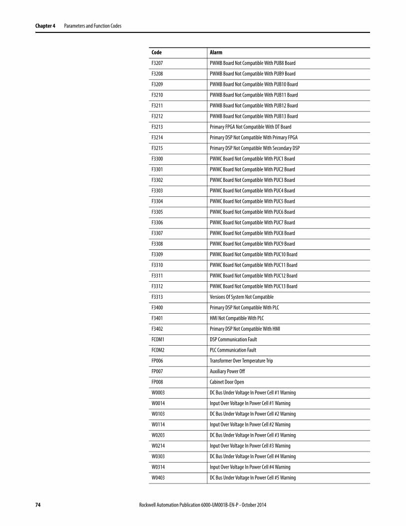
Chapter 4 Parameters and Function Codes
F3207 PWMB Board Not Compatible With PUB8 Board
F3208 PWMB Board Not Compatible With PUB9 Board
F3209 PWMB Board Not Compatible With PUB10 Board
F3210 PWMB Board Not Compatible With PUB11 Board
F3211 PWMB Board Not Compatible With PUB12 Board
F3212 PWMB Board Not Compatible With PUB13 Board
F3213 Primary FPGA Not Compatible With DT Board
F3214 Primary DSP Not Compatible With Primary FPGA
F3215 Primary DSP Not Compatible With Secondary DSP
F3300 PWMC Board Not Compatible With PUC1 Board
F3301 PWMC Board Not Compatible With PUC2 Board
F3302 PWMC Board Not Compatible With PUC3 Board
F3303 PWMC Board Not Compatible With PUC4 Board
F3304 PWMC Board Not Compatible With PUC5 Board
F3305 PWMC Board Not Compatible With PUC6 Board
F3306 PWMC Board Not Compatible With PUC7 Board
F3307 PWMC Board Not Compatible With PUC8 Board
F3308 PWMC Board Not Compatible With PUC9 Board
F3309 PWMC Board Not Compatible With PUC10 Board
F3310 PWMC Board Not Compatible With PUC11 Board
F3311 PWMC Board Not Compatible With PUC12 Board
F3312 PWMC Board Not Compatible With PUC13 Board
F3313 Versions Of System Not Compatible
F3400 Primary DSP Not Compatible With PLC
F3401 HMI Not Compatible With PLC
F3402 Primary DSP Not Compatible With HMI
FCOM1 DSP Communication Fault
FCOM2 PLC Communication Fault
FP006 Transformer Over Temperature Trip
FP007 Auxiliary Power Off
FP008 Cabinet Door Open
W0003 DC Bus Under Voltage In Power Cell #1 Warning
W0014 Input Over Voltage In Power Cell #1 Warning
W0103 DC Bus Under Voltage In Power Cell #2 Warning
W0114 Input Over Voltage In Power Cell #2 Warning
W0203 DC Bus Under Voltage In Power Cell #3 Warning
W0214 Input Over Voltage In Power Cell #3 Warning
W0303 DC Bus Under Voltage In Power Cell #4 Warning
W0314 Input Over Voltage In Power Cell #4 Warning
W0403 DC Bus Under Voltage In Power Cell #5 Warning
Code Alarm
74 Rockwell Automation Publication 6000-UM001B-EN-P - October 2014

Parameters and Function Codes Chapter 4
W0414 Input Over Voltage In Power Cell #5 Warning
W0503 DC Bus Under Voltage In Power Cell #6 Warning
W0514 Input Over Voltage In Power Cell #6 Warning
W0603 DC Bus Under Voltage In Power Cell #7 Warning
W0614 Input Over Voltage In Power Cell #7 Warning
W0703 DC Bus Under Voltage In Power Cell #8 Warning
W0714 Input Over Voltage In Power Cell #8 Warning
W0803 DC Bus Under Voltage In Power Cell #9 Warning
W0814 Input Over Voltage In Power Cell #9 Warning
W0903 DC Bus Under Voltage In Power Cell #10 Warning
W0914 Input Over Voltage In Power Cell #10 Warning
W1003 DC Bus Under Voltage In Power Cell #11 Warning
W1014 Input Over Voltage In Power Cell #11 Warning
W1103 DC Bus Under Voltage In Power Cell #12 Warning
W1114 Input Over Voltage In Power Cell #12 Warning
W1203 DC Bus Under Voltage In Power Cell #13 Warning
W1214 Input Over Voltage In Power Cell #13 Warning
W1303 DC Bus Under Voltage In Power Cell #14 Warning
W1314 Input Over Voltage In Power Cell #14 Warning
W1403 DC Bus Under Voltage In Power Cell #15 Warning
W1414 Input Over Voltage In Power Cell #15 Warning
W1503 DC Bus Under Voltage In Power Cell #16 Warning
W1514 Input Over Voltage In Power Cell #16 Warning
W1603 DC Bus Under Voltage In Power Cell #17 Warning
W1614 Input Over Voltage In Power Cell #17 Warning
W1703 DC Bus Under Voltage In Power Cell #18 Warning
W1714 Input Over Voltage In Power Cell #18 Warning
W1803 DC Bus Under Voltage In Power Cell #19 Warning
W1814 Input Over Voltage In Power Cell #19 Warning
W1903 DC Bus Under Voltage In Power Cell #20 Warning
W1914 Input Over Voltage In Power Cell #20 Warning
W2003 DC Bus Under Voltage In Power Cell #21 Warning
W2014 Input Over Voltage In Power Cell #21 Warning
W2103 DC Bus Under Voltage In Power Cell #22 Warning
W2114 Input Over Voltage In Power Cell #22 Warning
W2203 DC Bus Under Voltage In Power Cell #23 Warning
W2214 Input Over Voltage In Power Cell #23 Warning
W2303 DC Bus Under Voltage In Power Cell #24 Warning
W2314 Input Over Voltage In Power Cell #24 Warning
W2403 DC Bus Under Voltage In Power Cell #25 Warning
Code Alarm
Rockwell Automation Publication 6000-UM001B-EN-P - October 2014 75

Chapter 4 Parameters and Function Codes
W2414 Input Over Voltage In Power Cell #25 Warning
W2503 DC Bus Under Voltage In Power Cell #26 Warning
W2514 Input Over Voltage In Power Cell #26 Warning
W2603 DC Bus Under Voltage In Power Cell #27 Warning
W2614 Input Over Voltage In Power Cell #27 Warning
W2800 Motor Over Temperature Warning
W2801 Abnormal Output Voltage Warning
W2802 Ground Fault Warning
W2803 Output Frequency Deviation Warning
W3314 Version Fault Identification Code Error
WP001 Control Power Switch Warning
WP002 Transformer Cabinet Fan Fault
WP003 Power Module Cabinet Fan Fault
WP004 Transformer Over Temperature Warning
WP005 Analog Loss Warning
WP009 Power Module Cabinet Fan Circuit Breaker Open
WP010 Transformer Cabinet Fan Circuit Breaker Open
Code Alarm
76 Rockwell Automation Publication 6000-UM001B-EN-P - October 2014

Chapter 5
Preventative Maintenance and Component Replacement
Safety
Introduction The drive can experience reduced service life if operated outside of its design parameters. Ensure the operating environment is within specifications. Daily inspection and regular maintenance will maximize the service life of the equipment.
ATTENTION: Servicing energized Medium Voltage Motor Control Equipment can be hazardous. Severe injury or death can result from electrical shock, bump, or unintended actuation of controlled equipment. Recommended practice is to disconnect and lockout control equipment from power sources, and release stored energy, if present.For countries following NEMA standards, refer to National Fire Protection Association Standard No. NFPA70E, Part II and (as applicable) OSHA rules for Control of Hazardous Energy Sources (Lockout/Tagout) and OSHA Electrical Safety Related Work Practices safety related work practices, including procedural requirements for lockout/tagout, and appropriate work practices, personnel qualifications and training requirements, where it is not feasible to de-energize and lockout or tagout electric circuits and equipment before working on or near exposed circuit parts.For countries following IEC standards, refer to local codes and regulations.
ATTENTION: Use suitable personal protective equipment (PPE) per local codes or regulations. Failure to do so may results in severe burns, injury, or death.
ATTENTION: Always perform Power Lockout procedure before servicing equipment. Verify with a hot stick or appropriate voltage measuring device that all circuits are voltage free. Failure to do so may result in severe burns, injury, or death.
ATTENTION: These tasks require person(s) skilled in this type of detailed work. Read and understand this manual thoroughly before commencing. Contact Rockwell Automation with any questions or for clarification.
Rockwell Automation Publication 6000-UM001B-EN-P - October 2014 77
Chapter 5 Preventative Maintenance and Component Replacement
Daily Inspection
Check the following items during normal operation of the drive:• abnormal noise or vibration in the drive or motor• abnormal temperature in the drive or motor• ambient temperature in the control room above nominal• accumulation of dust or particulate on control room floor or surfaces• abnormal load current above nominal
Regular Maintenance Intervals
The annual maintenance requirements are summarized on page 123 as a guideline. Detailed procedures referred to in the Preventative Maintenance Schedule are described beginning on page 81.
Medium Voltage Motor control equipment should be inspected periodically. Inspection intervals should be based on environmental and operating conditions and adjusted as indicated by experience. An initial comprehensive inspection, within 3 to 4 months after installation, is suggested. Refer to the following standards for general guidelines for setting-up a periodic maintenance program.For countries following NEMA standards, refer to National Electrical Manufacturers Association (NEMA) Standard No. ICS 1.1 (Safety Guidelines for the Application, Installation, and Maintenance of Solid-Sate Control) for MV Drives and ICS 1.3 (Preventive Maintenance of Industrial Control and Systems Equipment) for MV Controllers. For countries following IEC standards, refer to IEC 61800-5-1 Sec. 6.5 for MV Drives and IEC 60470 Sec. 10, IEC 62271-1 Sec. 10.4 for MV Controllers.
If inspection reveals that dust, dirt, moisture or other contamination has reached the control equipment, the cause must be eliminated. This could indicate unsealed enclosure openings (conduit or other) or incorrect operating procedures. Replace any damaged or embrittled seals, and repair or replace any other damaged or malfunctioning parts. Replace dirty, wet, or contaminated control devices unless they can be cleaned effectively by vacuuming or wiping.
IMPORTANT Compressed air is not recommended for cleaning because it may displace dirt, dust, or debris into other parts or equipment, or damage delicate parts.
78 Rockwell Automation Publication 6000-UM001B-EN-P - October 2014

Preventative Maintenance and Component Replacement Chapter 5
Physical Checks (No Medium Voltage or Control Power)
Power Connection Inspection• Inspect PowerFlex 6000 drive, input/output/bypass sections, and all
associated drive components for loose power cable connections and ground cable connections: torque them based on the required torque specifications.
• Inspect the bus bars and check for any signs of overheating / discoloration and tighten the bus connections to the required torque specifications.
• Clean all cables and bus bars that exhibit dust build-up. • The torques of incoming / outgoing cable screws of the power unit shall be
check if they are in the specified range.• Use torque sealer on all connections. Carry out the integrity checks on the
signal ground and safety grounds.
Physical Inspection• Check for any visual/physical evidence of damage or degradation of
components in the low voltage compartments. – This includes Relays, Contactors, Timers, Terminal connectors, Circuit
breakers, Ribbon cables, Control Wires, UPS, AC/DC Power Supplies etc.; Causes could be corrosion, excessive temperature, or contamination.
• Check for any visual/physical evidence of damage or degradation of components in the medium voltage compartments (cables, contactors, circuit breakers, isolation disconnecting blades, power units, etc.). – This includes main cooling fan, power devices, heat sinks, circuit
boards, insulators, cables, capacitors, current transformers, potential transformers, fuses, wiring, etc.; Causes could be corrosion, excessive temperature, or contamination.
• Clean all contaminated components using a vacuum cleaner (DO NOT use a blower), and wipe clean components where appropriate.
• Carry out the physical inspection and verification for the proper operation of the contactor/isolator interlocks, and door interlocks.
• Carry out the physical inspection and verification for the proper operation of the key interlocks.
• Carry out the cleaning of the fans and ensure that the ventilation passages are not blocked and the impellers are freely rotating without any obstruction.
• Carry out the insulation megger test on the transformer, motor, and associated cabling.
• Check all bolts for fastening and adjust them as necessary.
Rockwell Automation Publication 6000-UM001B-EN-P - October 2014 79

Chapter 5 Preventative Maintenance and Component Replacement
Medium Voltage Testing
Medium voltage insulation resistance (IR) or dielectric withstanding voltage (megger) tests should not be used to check solid-state control equipment. When meggering electrical equipment, such as transformers or motors, solid-state devices must be bypassed before performing the test. Even though no damage may be readily apparent after a megger test, the solid-state devices are degraded and repeated application of high voltage can lead to failure.
Maintenance after a Fault Condition
Opening of the short circuit protective device (such as fuses or circuit breakers) in a properly coordinated motor branch circuit is an indication of a fault condition in excess of operating overload. Such conditions can cause damage to medium voltage motor control equipment. Before restoring power, the fault condition must be corrected and any necessary repairs or replacements must be made to restore the medium voltage motor control equipment to good working order. Refer to NEMA Standards Publication No. ICS-2, Part ICS2-302 for procedures. Use only replacement parts and devices recommended by Rockwell Automation to maintain the integrity of the equipment. Ensure the parts are properly matched to the model, series and revision level of the equipment. After maintenance or repair of the equipment, always test the control system for proper functioning under controlled conditions (that avoid hazards in the event of a control malfunction). For additional information, refer to NEMA ICS 1.3, PREVENTIVE MAINTENANCE OF INDUSTRIAL CONTROL AND SYSTEMS EQUIPMENT, published by the National Electrical Manufacturers Association, and NFPA70B, ELECTRICAL EQUIPMENT MAINTENANCE, published by the National Fire Protection Association.
Final Report A complete, detailed report on all steps in the Preventive Maintenance procedures should be recorded to identify changes.
A detailed description of all adjustments and measurements that were taken during the process must be recorded (Interlock Adjustments, Loose Connections, Voltage Readings, Megger Results, Parameters, etc.).
80 Rockwell Automation Publication 6000-UM001B-EN-P - October 2014

Preventative Maintenance and Component Replacement Chapter 5
Isolation Transformer Cabinet
Replace/Clean Door Mounted Air Filters
Periodically remove and clean, or remove and replace, the air filters according to the Preventative Maintenance table on page 124. The frequency with which you renew the filters depends on the cleanliness of the available cooling air.
The cabinet door filters are installed in six locations, including four locations on the Power Module Cabinet, and two locations on the Isolation Transformer Cabinet. However, the method to remove or clean the air filters is the same. The screens may be replaced while the drive is operating, but the procedure is easier to perform while the drive is shut down.
If the drive is running, you must replace the filter as soon as possible to prevent foreign material from entering into the drive.
Recommended Cleaning Method of Filters:• Vacuum Cleaner – A vacuum cleaner on the inlet side of the filter will
remove accumulated dust and dirt.• Blow with Compressed Air – point compressed air nozzle in opposite
direction of operating air flow (Blow from exhaust side toward intake side)• Cold Water Rinse – Under normal conditions the foam media used in the
filters, require no oily adhesives. Collected dirt is washed away quickly and easily using just a standard hose nozzle with plain water.
• Immersion in Warm Soapy Water – Where stubborn air-borne dirt is present, the filter may be dipped in a solution of warm water and mild detergent. Rinse in clear clean water, let stand until completely dry and free of moisture.
Replace/Clean Door Mounted Air Filters 81
Inspect Top Mounted Main Cooling Fans 82
Replace Top Mounted Main Cooling Fans 83
Fan Balance 84
Inspect Isolation Transformer Auxiliary Cooling Fans 85
Replace Isolation Transformer Auxiliary Cooling Fans 86
Inspect Isolation Transformer 86
Inspect Voltage Sensing Board 87
Replace Voltage Sensing Board 87
Inspect Door Position Limit Switch 88
Replace Door Position Limit Switch 89
ATTENTION: The filter must be completely dry before reinstalling.
Rockwell Automation Publication 6000-UM001B-EN-P - October 2014 81

Chapter 5 Preventative Maintenance and Component Replacement
Use only Rockwell Automation-supplied or -approved replacement filters (see Spare Parts List on page 127). Replace the filters in the reverse order of its removal. Check that there are no openings to allow foreign matter to enter the drive.
1. Unlatch and open the cabinet filter door more than 90°.
2. Remove the screens by pulling up out of the door.
3. Re-install the cleaned or new air filter using reverse order of removal. Ensure the door is fully closed and locked.
Inspect Top Mounted Main Cooling Fans
Inspect fans used for forced air cooling. Replace any that have bent, chipped, or missing blades, or if the shaft does not turn freely. Apply power momentarily to check operation. If unit does not operate, check and replace wiring, fuse, or fan motor as appropriate. Clean or change air filters as recommended in the Users Manual. Ensure the aviation plug has a proper hand-tight connection. Ensure that the ventilation passages are not blocked and the impellers can rotate freely without any obstruction.
IMPORTANT When removing the filter, prevent accumulated dirt on the inlet side of the filter from being sucked into the drive. It may be difficult to remove the filter material without tearing due to the suction at the air inlet.
82 Rockwell Automation Publication 6000-UM001B-EN-P - October 2014

Preventative Maintenance and Component Replacement Chapter 5
Replace Top Mounted Main Cooling Fans
The top fan housing consists of a motor and impeller assembly. To replace the fan, it is necessary to remove the Fan Housing Lid.
1. Remove and retain four tapping screws around the Fan Housing Lid, and remove the Lid.
2. Remove and retain eight M6 x 12 bolts from the Fan Housing Assembly which connect to the Fan Support Bracket.
ATTENTION: Fan replacement requires working at a significant height from the floor. Complete this procedure on a safe, stable platform.
ATTENTION: Always perform Power Lockout procedure before servicing equipment. Verify with a hot stick or appropriate voltage measuring device that all circuits are voltage free. Failure to do so may result in severe burns, injury, or death.
M6 x 12 Bolt (4)
Lock washer (4)
Washer (4)
Tapping Screw (4)
M6 x 12 Bolt (8)
Washer (16)
Washer (16)
Lock washer (8)
Fan Housing Lid
Fan Support Bracket
Fan Housing Assembly
Fan Assembly
Wiring Cover
Aviation Plug
Rockwell Automation Publication 6000-UM001B-EN-P - October 2014 83

Chapter 5 Preventative Maintenance and Component Replacement
3. Remove and retain four M6 x 12 bolts from the top of the Fan Support Bracket, and remove the bracket from the Fan Assembly.
4. Remove the Wiring Cover and disconnect the wiring.
5. Install the fan in the reverse order of its removal. Rotate the impeller by hand to ensure that there is no contact with the Fan Housing Assembly.
Fan Balance
Fan impellers are statically and dynamically balanced within acceptable tolerances at the factory. Damage in shipping or from incorrect handling or installation may upset the balance. An improperly balanced impeller can lead to excessive vibration causing undue wear on the entire unit.
If vibration is excessive, shut down the fan and determine the cause. Common causes of excessive vibration include:
• Drive support structure not sufficiently rigid or level• Loose mounting bolts• Loose impeller or bushing
ATTENTION: The fan must be handled with extreme care. Failure to do so can alter the fan balance and will negatively impact performance and life span.
84 Rockwell Automation Publication 6000-UM001B-EN-P - October 2014

Preventative Maintenance and Component Replacement Chapter 5
Inspect Isolation Transformer Auxiliary Cooling Fans
When the drive is running, verify that each of the coil temperatures are the same on the Isolation Transformer Temperature Monitor display. If there is more than a 5 °C difference between the highest and lowest temperature, check the Isolation Transformer Auxiliary Cooling Fans.
Test the Isolation Transformer Auxiliary Cooling Fans:
1. Open the LV Control Door on the Isolation Transformer Cabinet.
Locate the correct circuit breaker(s).
2. Disconnect the wires from the load side of the Isolation Transformer Auxiliary Cooling Fan circuit breaker. Refer to Electrical Drawings.
Figure 25 - Circuit Breaker Location on LV Control Door
3. Connect 380V power to the wires to verify operation of the fans.
If a fan is not operational, see Replace Isolation Transformer Auxiliary Cooling Fans on page 86.
4. Remove the power source and reconnect the wires to the circuit breaker.
ATTENTION: Verify that all circuits are voltage-free, using a hot stick or appropriate high voltage-measuring device. Failure to do so may result in injury or death.
Rockwell Automation Publication 6000-UM001B-EN-P - October 2014 85
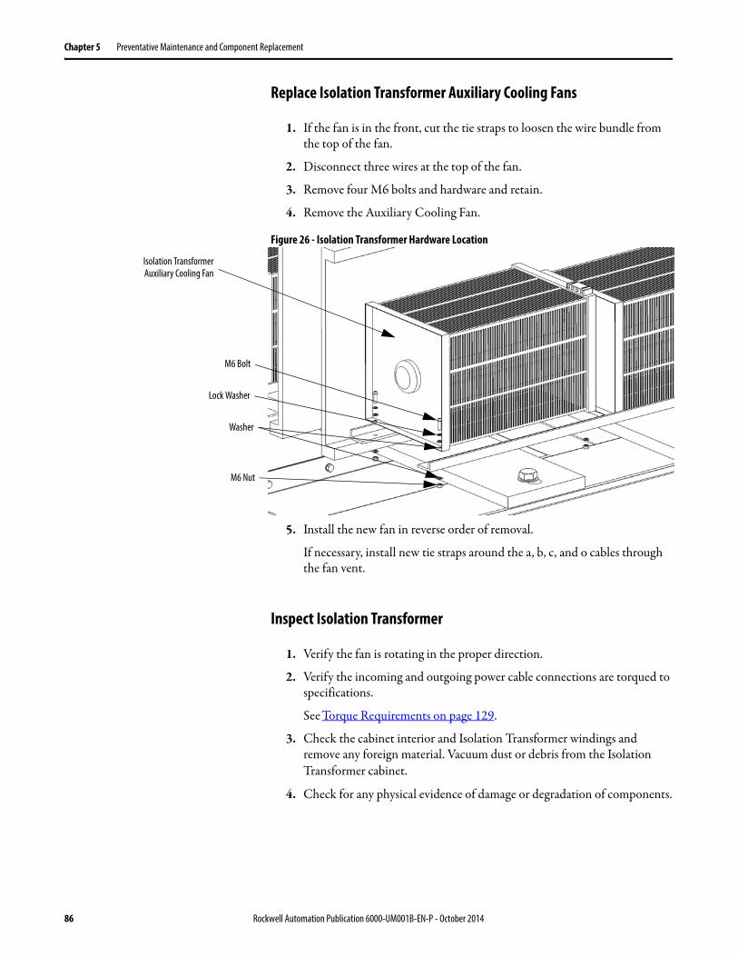
Chapter 5 Preventative Maintenance and Component Replacement
Replace Isolation Transformer Auxiliary Cooling Fans
1. If the fan is in the front, cut the tie straps to loosen the wire bundle from the top of the fan.
2. Disconnect three wires at the top of the fan.
3. Remove four M6 bolts and hardware and retain.
4. Remove the Auxiliary Cooling Fan.
Figure 26 - Isolation Transformer Hardware Location
5. Install the new fan in reverse order of removal.
If necessary, install new tie straps around the a, b, c, and o cables through the fan vent.
Inspect Isolation Transformer
1. Verify the fan is rotating in the proper direction.
2. Verify the incoming and outgoing power cable connections are torqued to specifications.
See Torque Requirements on page 129.
3. Check the cabinet interior and Isolation Transformer windings and remove any foreign material. Vacuum dust or debris from the Isolation Transformer cabinet.
4. Check for any physical evidence of damage or degradation of components.
M6 Bolt
Lock Washer
Washer
M6 Nut
Isolation TransformerAuxiliary Cooling Fan
86 Rockwell Automation Publication 6000-UM001B-EN-P - October 2014
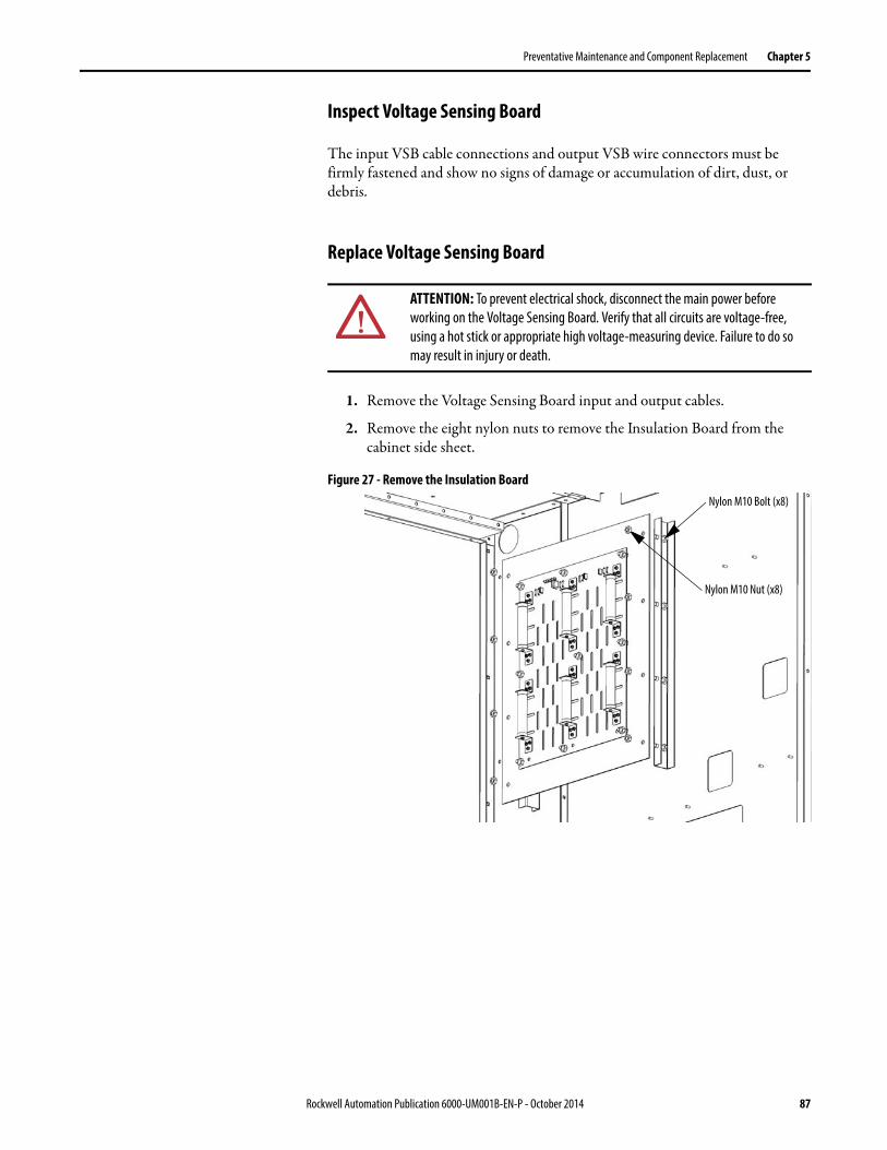
Preventative Maintenance and Component Replacement Chapter 5
Inspect Voltage Sensing Board
The input VSB cable connections and output VSB wire connectors must be firmly fastened and show no signs of damage or accumulation of dirt, dust, or debris.
Replace Voltage Sensing Board
1. Remove the Voltage Sensing Board input and output cables.
2. Remove the eight nylon nuts to remove the Insulation Board from the cabinet side sheet.
Figure 27 - Remove the Insulation Board
ATTENTION: To prevent electrical shock, disconnect the main power before working on the Voltage Sensing Board. Verify that all circuits are voltage-free, using a hot stick or appropriate high voltage-measuring device. Failure to do so may result in injury or death.
Nylon M10 Nut (x8)
Nylon M10 Bolt (x8)
Rockwell Automation Publication 6000-UM001B-EN-P - October 2014 87

Chapter 5 Preventative Maintenance and Component Replacement
3. Remove the nylon nuts which connect the Voltage Sensing Board to the Insulation Board.
Figure 28 - Remove the Voltage Sensing Board from the Insulation Board
4. Install the new Voltage Sensing Board to the Insulation Board in reverse order of removal.
5. Reinstall the Insulation Board to the cabinet side sheet in reverse order of removal.
6. Reconnect the input and output cables according to the Electrical Drawings.
Inspect Door Position Limit Switch
Check for obvious signs of damage, dust, or foreign material. Remove any dirt or foreign material. Wipe components with an anti-static cloth, where applicable. Check the aviation plug has a hand-tight connection.
Nylon M10 Nut (x9)
Nylon M10 Nut (x9)
Insulation Board
Voltage Sensing Board
88 Rockwell Automation Publication 6000-UM001B-EN-P - October 2014

Preventative Maintenance and Component Replacement Chapter 5
Replace Door Position Limit Switch
1. Open the drive cabinet door.
2. Disconnect the aviation plug from the back of the Limit Switch.
3. Remove two M4 x 35 bolts and hardware from the mounting bracket.
4. Install the new Limit Switch in reverse order of removal.
Figure 29 - Replace Door Position Limit Switch
ATTENTION: Ensure the input circuit breaker feeding the drive is open. Lock out and tagout the input circuit breaker before performing any work on the drive or bypass units.
Nut
Lock washer
Washer
M4 x 35 Bolt
Aviation Plug
Rockwell Automation Publication 6000-UM001B-EN-P - October 2014 89

Chapter 5 Preventative Maintenance and Component Replacement
Power Module Cabinet
Inspect, Clean, or Replace Door Mounted Air Filters
See Replace/Clean Door Mounted Air Filters on page 81.
Inspect or Replace Top Mounted Main Cooling Fans
See Inspect Top Mounted Main Cooling Fans on page 82.
Inspect Power Modules
1. Check for damage or degradation of the Power Modulesa. Inspect the power connections for loose connections or any evidence of
discoloration of connections from heatingb. For Drawout Power Module configurations, remove the back plates
from the Power Module Cabinet and inspect the plug-in connectors on the back of each Power Module. Look for evidence of discoloration from overheating.
2. Remove dust or debris from all ventilation openings on the Power Module
3. Inspect the electrolytic capacitors, located in the ventilation openings of the Power Module.a. Inspect for signs of discoloration, odor, or leakage.b. Replace Power Modules if the capacitors have discoloration, odor, or
leakage.
Inspect, Clean, or Replace Door Mounted Air Filters 90
Inspect or Replace Top Mounted Main Cooling Fans 90
Inspect Power Modules 90
Replace Power Module 91
Install Drawout Power Modules 95
Replace Power Module Fuses 97
Inspect or Replace HECS 99
Inspect or Replace Door Position Limit Switch 100
90 Rockwell Automation Publication 6000-UM001B-EN-P - October 2014

Preventative Maintenance and Component Replacement Chapter 5
Replace Power Module
Table 7 - Power Module Specifications
Fixed-mounted Power Module
1. Remove the positioning barriers from both sides of the Power Module.
2. Disconnect the Three-phase Input Power Cables.
Figure 30 - Fixed-mounted Power Module Component Location
Type Output Rating (Amps) Dimensions (HxWxD), approx. Weight, approx.
Fixed-mounted ≤150 A 420 x 180 x 615 mm (16.5 x 7.1 x 24.2 in.) 20 kg (44.1 lb)
151...200 A 420 x 260 x 615 mm (16.5 x 10.2 x 24.2 in.) 25 kg (55.1 lb)
Drawout 201...380 A 575 x 342 x 691 mm (22.6 x 13.5 x 27.2 in.) 40 kg (88.2 lb)
381...420 A 575 x 342 x 910 mm (22.6 x 13.5 x 35.8 in.) 50 kg (110.2 lb)
ATTENTION: Two people are required to handle the Power Modules. Always handle the drawout Power Modules using the two recessed lifting handles on both mounting rails (Figure 33).
ATTENTION: The high-voltage power source must be switched off before replacing a Fixed-mounted Power Module. Wait for 20 minutes before opening the cabinet doors. Verify that all circuits are voltage-free, using a hot stick or appropriate high voltage-measuring device. Failure to do so may result in injury or death.
Fuse
Positioning Barriers
Output Copper Bar (not shown)Connection Location
Fiber Optic Cables Connection Point
Three-phase Input Cablesfrom Isolation Transformer
Center Jumper Bar
Rockwell Automation Publication 6000-UM001B-EN-P - October 2014 91

Chapter 5 Preventative Maintenance and Component Replacement
3. Remove the Output Copper Bars that connect adjacent Power Modules (Figure 31).
If the Power Module is at the end of a row, remove the VSB and Motor cable instead of an output copper bus.
4. Disconnect the fiber optic cables.
Figure 31 - Close up of Fiber Optic Location and Power Cables
5. Carefully withdraw the Power Module.
6. Install the new Power Module in reverse order of removal.
ATTENTION: When removing the fiber optic cables, be careful to prevent the cables from straining or crimping as the resulting loss in light transmission will impact performance.
ATTENTION: Minimum bend radius permitted for the fiber optic cables is 50 mm (2.0 in.). Any bends with a shorter inside radius can permanently damage the fiber-optic cable.
Motor Cable
VSB Cable
Output Copper Bar
Fiber Optic Cables
92 Rockwell Automation Publication 6000-UM001B-EN-P - October 2014

Preventative Maintenance and Component Replacement Chapter 5
Replace Drawout Power Module
Lift Carts are supplied and shipped separately with drawout power module configurations. The unit’s hydraulic cylinder can be operated by either a hand or foot crank. The lifting capacity is 1000 kg (2206 lb).
Figure 32 - Lift Cart Procedure
ATTENTION: Only authorized personnel should operate the lift cart. Keep hands and feet away from the lifting mechanism. Do not stand under the lift tray when in use. Store the lift cart with the tray fully lowered.
Hand Crank
Foot Crank
Pressure Release Knob
1. Visually inspect the lift cart to ensure it is fully operational.
2. Turn the Pressure Release Knob clockwise until tight.
3. Raise the lift tray using the Hand Crank or the Foot Crank.
4. Lower the lift tray by turning the Pressure Release Knob counter-clockwise.
TIP The Foot Crank raises the lift tray faster than the Hand Crank. Use this to raise the Power Module to just below the tray assembly in the drive. Use the Hand Crank for final precise positioning.
Lift Tray
Release Pressure in Cylinder
Seal Pressure in Cylinder
Rockwell Automation Publication 6000-UM001B-EN-P - October 2014 93

Chapter 5 Preventative Maintenance and Component Replacement
Figure 33 - Drawout Power Module Lifting Handles
Recessed Lifting Handles
Mounting RailFinger Assemblies
ATTENTION: Do not use the front mounted positioning handles for lifting the Power Modules. They are designed to position or withdraw the Power Module when on the tray assembly.
94 Rockwell Automation Publication 6000-UM001B-EN-P - October 2014

Preventative Maintenance and Component Replacement Chapter 5
Install Drawout Power Modules
1. Place the Power Module module on the lift cart.
Ensure the Power Module is properly oriented; the finger assemblies must face towards the drive.
2. Position the lift cart in front of the cabinet and raise the Power Module to the proper height.
3. Align the wheels on the Power Module with the tray assembly guides on each side of the Power Module tray assembly.
4. Push the Power Module slowly backwards into the cabinet until the cam mechanism contacts the pin mounted on the tray assembly.
Wheels
Tray Assembly Guides
Cam Mechanism Actuator
Power Module Positioning
Handles
Rockwell Automation Publication 6000-UM001B-EN-P - October 2014 95

Chapter 5 Preventative Maintenance and Component Replacement
5. Insert the locking key into the cam mechanism actuator and rotate clockwise while gently pushing on the face of the Power Module.
The cam mechanism will catch the pin on the tray assembly.
6. Continue rotating the locking key until the Power Module is fully seated.
This ensures the finger assemblies at the back of the Power Module are fully connected to the stab assemblies at the back of the Power Module compartment.
Locking Key
Pin
Cam Mechanism
CabinetStab
AssembliesFinger
Assemblies
SIDE VIEW
Connection toMotor Phase Bus
Three PhaseInput Power
from IsolationTransformer
Pin
Cam MechanismTOP VIEW
Locking Key
Cam Mechanism Actuator
ATTENTION: The Power Module finger assemblies must be fully seated on the cabinet stab assemblies.
96 Rockwell Automation Publication 6000-UM001B-EN-P - October 2014
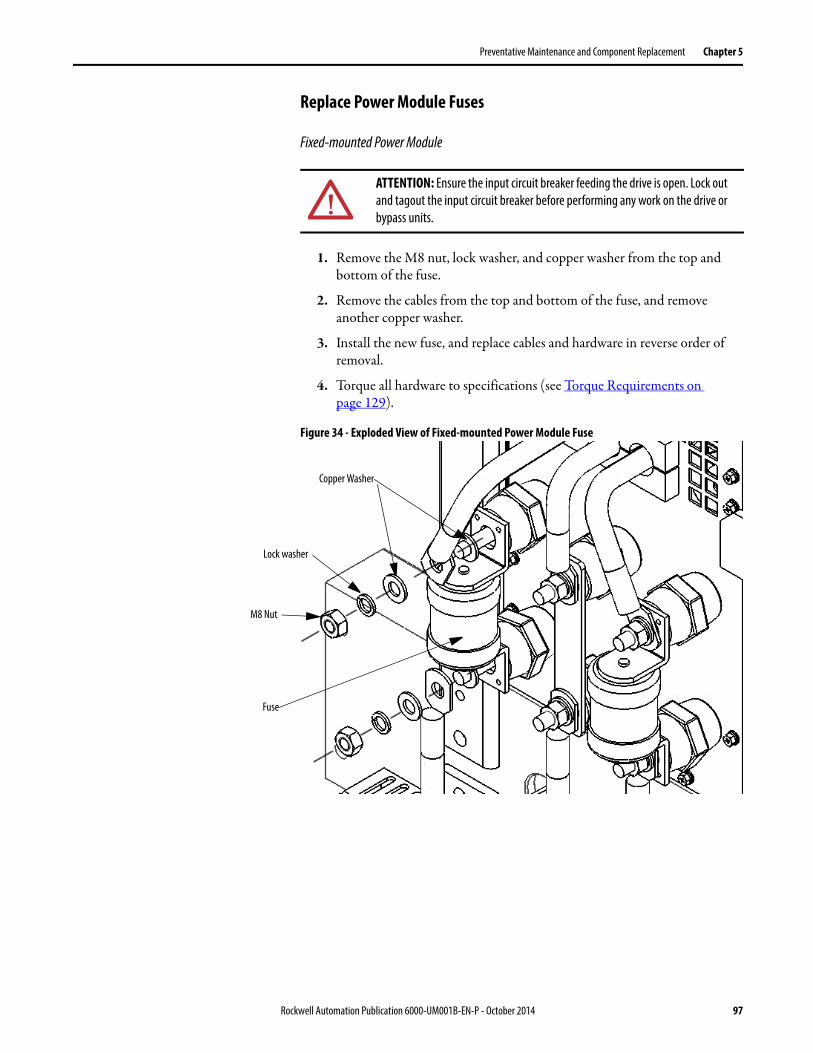
Preventative Maintenance and Component Replacement Chapter 5
Replace Power Module Fuses
Fixed-mounted Power Module
1. Remove the M8 nut, lock washer, and copper washer from the top and bottom of the fuse.
2. Remove the cables from the top and bottom of the fuse, and remove another copper washer.
3. Install the new fuse, and replace cables and hardware in reverse order of removal.
4. Torque all hardware to specifications (see Torque Requirements on page 129).
Figure 34 - Exploded View of Fixed-mounted Power Module Fuse
ATTENTION: Ensure the input circuit breaker feeding the drive is open. Lock out and tagout the input circuit breaker before performing any work on the drive or bypass units.
Copper Washer
Lock washer
M8 Nut
Fuse
Rockwell Automation Publication 6000-UM001B-EN-P - October 2014 97

Chapter 5 Preventative Maintenance and Component Replacement
Drawout Power Module
1. Remove and retain the M12 bolt, washer, lock washer, and nut from the top and bottom of the fuse.
2. Remove the fuse from between the fixed bracket and the power cable and bus bar.
3. Install the new fuse, and the hardware in reverse order of removal.
4. Torque all hardware to specifications (see Torque Requirements on page 129).
Figure 35 - Exploded View of Fixed-mounted Power Module Fuse
ATTENTION: Ensure the input circuit breaker feeding the drive is open. Lock out and tagout the input circuit breaker before performing any work on the drive or bypass units.
ATTENTION: The hardware connecting the Drawout Power Modules MUST be reinstalled facing up, as shown in Figure 35. Failure to install the hardware in this manner will affect clearance distance between bolts and can cause an arc.
Washer
Lock washer
M12 x 30 Bolt
Fuse
Washer
Nut
Power Cable
Bus bar
98 Rockwell Automation Publication 6000-UM001B-EN-P - October 2014

Preventative Maintenance and Component Replacement Chapter 5
Inspect or Replace HECS
Two current sensors are located at the top inside the Power Module Cabinet. Verify that the current sensor wire connector is properly seated. Check for obvious signs of damage.
1. Unplug the Current Sensor Connector from the HECS.
2. Disconnect one end of the power cable that goes through the HECS from the Power Module.
3. Remove the Mounting Bracket with the HECS still attached.
ATTENTION: To prevent electrical shock, disconnect the main power before working on the drive. Verify that all circuits are voltage-free, using a hot stick or appropriate high voltage-measuring device. Failure to do so may result in injury or death.
Current Sensor Connection
HECS
Mounting Bracket
Rockwell Automation Publication 6000-UM001B-EN-P - October 2014 99

Chapter 5 Preventative Maintenance and Component Replacement
4. Remove and retain M5 x 12 hardware connecting the HECS to the Mounting Bracket.
Figure 36 - Exploded view of the HECS and Mounting Bracket
5. Install the HECS on the Mounting Bracket using the existing hardware.
6. Install the Mounting Bracket to the cabinet using existing hardware.
7. Reroute the power cable through the HECS and reattach to the Power Module.
Inspect or Replace Door Position Limit Switch
See Replace Door Position Limit Switch on page 89.
IMPORTANT Note the orientation of the HECS on the bracket. The new HECS must be installed facing the same direction.
M5 x 12 Nut
M5 x 12 Nut
Washer
ATTENTION: Verify that the current sampling direction is correct. This is indicated by an arrow symbol on the top of the HECS.
100 Rockwell Automation Publication 6000-UM001B-EN-P - October 2014

Preventative Maintenance and Component Replacement Chapter 5
LV Control Cabinet
Inspect AC/DC Power Supplies
Ensure the input and output terminal connections are tight.
Use a voltmeter to check the output voltage. A green LED indicates normal operation.
Figure 37 - AC/DC Power Supplies
Inspect AC/DC Power Supplies 101
Replace AC/DC Power Supplies 102
Inspect UPS 104
Replace UPS 105
Replace UPS Batteries 106
Inspect PLC 108
Inspect/Replace Control Unit or Control Boards 108
Inspect the HMI 111
Replace the HMI 111
Replace LV Control Relays 113
Replace LV Control Circuit Breakers 114
Inspect Coils 116
Inspect Contacts 116
Inspect Pilot Lights 116
Inspect Locking and Interlocking Devices 116
N L N L
G1
G2
G3
Rockwell Automation Publication 6000-UM001B-EN-P - October 2014 101

Chapter 5 Preventative Maintenance and Component Replacement
Replace AC/DC Power Supplies
G1 or G2 Power Supplies
1. Open the LV Control cabinet door.
2. Loosen the top and bottom terminal screws and remove the wires on the G1 or G2 power supplies.
Figure 38 - Remove AC/DC Power Supply wires (G3 Power Supply not shown for clarity)
3. Release the spring-loaded latches at the bottom of the power supply and lift the control relay off the DIN rail.
Figure 39 - Release the latches on the Power Supplies (G3 Power Supply not shown for clarity)
4. Install the new power supply in reverse order of removal.
ATTENTION: Always perform Power Lockout procedure before servicing equipment. Verify with a hot stick or appropriate voltage measuring device that all circuits are voltage free. Failure to do so may result in severe burns, injury, or death.
Unscrew the connecting wires on the top and bottom
102 Rockwell Automation Publication 6000-UM001B-EN-P - October 2014

Preventative Maintenance and Component Replacement Chapter 5
G3 Power Supply
1. Loosen, but do not remove, the screws on the top of the G3 Power Supply.
2. Remove the wires.
Figure 40 - Remove G3 Power Supply wires (G1 and G2 Power Supply not shown for clarity)
3. Remove two M3 Tapping screws to remove the unit.
Figure 41 - Remove AC/DC Power Supply
4. Install the new power supply in reverse order of removal.
Loosen screws and remove all wires
M3 Tapping Screw
Rockwell Automation Publication 6000-UM001B-EN-P - October 2014 103

Chapter 5 Preventative Maintenance and Component Replacement
Inspect UPS
1. Check there are no obstructions or dirt/debris in the exhaust heat fan.
2. Ensure there are no visible signs of damage.
Check UPS Output Voltage
1. Open the LV Control cabinet door.
2. Turn off the back-up control power circuit breaker (Q5) and the customer-supplied power supply circuit breaker (Q1).
Figure 42 - Circuit Breaker Location in LV Control Cabinet
3. Press ON on the front of the UPS.
4. Using a voltmeter, check the output voltage of the UPS by checking the input voltage on the line side of the Q2 circuit breaker (equivalent electrical point).
The input voltage must be 220V AC.
IMPORTANT If the drive has not been turned on for more than 3 months, the UPS batteries must be charged for at least 10 hours. Apply either MV to the drive or customer-supplied control power.
Q1 Q2 Q3 Q6Q5
Circuit Breakers
PLC
LV Control Relays
104 Rockwell Automation Publication 6000-UM001B-EN-P - October 2014

Preventative Maintenance and Component Replacement Chapter 5
Replace UPS
1. Turn off the Q2, Q3, and Q6 circuit breakers in the LV Control Cabinet (Figure 42).
2. Press and hold OFF on the front of the UPS.
Figure 43 - Front Display of UPS
3. Turn off the Q1 and Q5 circuit breakers in the LV Control Cabinet.
4. Unplug the UPS input and output power cables and disconnect the ground wire.
5. Remove and retain four screws from the mounting bracket.
ATTENTION: Always perform Power Lockout procedure before servicing equipment. Verify with a hot stick or appropriate voltage measuring device that all circuits are voltage free. Failure to do so may result in severe burns, injury, or death.
Press and hold for3 seconds to turn
the UPS off
M5 x 12 Bolt (x4)
Mounting Bracket
Rockwell Automation Publication 6000-UM001B-EN-P - October 2014 105

Chapter 5 Preventative Maintenance and Component Replacement
6. Install the replacement UPS, and reconnect input and output cables.
7. Turn the Q1 circuit break and press the ON button on the UPS.
Wait for 2...3 seconds.
8. Using a voltmeter, check the input voltage on the line side of the Q2 circuit breaker.
The input voltage must be 220V AC.
9. Turn on Q2, Q3, Q5, and Q6 circuit breakers to complete the procedure.
Replace UPS Batteries
The UPS must be removed from the LV Control Cabinet in order to access and replace the batteries. See steps 1...5 of Replace UPS on page 105 for instruction on safely removing the UPS.
Remove the UPS Batteries
1. Remove and retain seven screws from the outside of the UPS enclosure (two screws on either side and three screws on the back).
2. Remove the outer UPS cover and set aside.
Figure 44 - Remove the UPS enclosure hardware
ATTENTION: During removal and installation of the UPS, do not omit the UPS ground wire.
ATTENTION: Do not handle batteries that have leaked electrolytes, as they are corrosive and can cause burns.
UPS Enclosure
106 Rockwell Automation Publication 6000-UM001B-EN-P - October 2014

Preventative Maintenance and Component Replacement Chapter 5
3. Remove the cables from the top battery one at a time, and immediately wrap insulating tape around end of each cable.
Indicate on the tape the positive or negative terminal, as appropriate.
4. Repeat step 2 for the two remaining batteries.
5. Remove and retain two screws on either side of the mounting bracket, and remove the bracket.
Figure 45 - Remove the mounting bracket
6. Remove the batteries from the UPS.
7. Place the new batteries in the enclosure, and reinstall the mounting bracket using the hardware removed in step 5.
8. Reconnect the cables to the correct terminals on each battery.
9. Use a voltmeter to check the output of the batteries. The total voltage must be 37...40V DC.
10. Install the UPS enclosure using the hardware removed in step 1.
See step 6...9 of Replace UPS on page 105 to reinstall the UPS.
ATTENTION: Do not touch the positive and negative battery wires to each other or the UPS enclosure.
Do NOT throw batteries in the garbage. Dispose of the batteries according to local regulations.
Rockwell Automation Publication 6000-UM001B-EN-P - October 2014 107

Chapter 5 Preventative Maintenance and Component Replacement
Inspect PLC
1. Verify all input and output terminal connections are secure.
2. Verify all LEDs are working and indicate normal status.
See publication 2080-UM002_-EN-P for further information for the PLC, or publication 2080-WD002_-EN-P for further information regarding the Isolated Serial Port Plug-in Modules.
Inspect/Replace Control Unit or Control Boards
• Verify that the terminal connections on the bottom of the Control Unit are secure and are free of dirt, dust, or foreign material. Clean with an anti-static cloth.
• Verify the fiber optic cables are properly connected to the A/B/C PWM boards. Verify an appropriate bend radius (if applicable).
• Check all boards for damage and properly working LEDs.
Replace a Control Unit
1. Turn off all the control power, turn off the UPS, and confirm the LV Control Cabinet is unenergized before operation.
2. Disconnect all of the bottom terminals.
3. Disconnect the fiber optic wires from A/B/C Phase board.
4. Disconnect the HMI communication cable from the CPU board.
5. Remove four M6 x 12 bolts, and remove the Control Unit.
ATTENTION: Always perform Power Lockout procedure before servicing equipment. Verify with a hot stick or appropriate voltage measuring device that all circuits are voltage free. Failure to do so may result in severe burns, injury, or death.
IMPORTANT The Control Unit does not have to be removed to replace Control Boards.
ATTENTION: When removing the fiber optic cables, be careful to prevent the cables from straining or crimping as a resulting loss in light transmission will impact performance.
108 Rockwell Automation Publication 6000-UM001B-EN-P - October 2014

Preventative Maintenance and Component Replacement Chapter 5
Figure 46 - Remove Retaining Screws of Control Unit
6. Install the new Control Unit in reverse order of removal. Refer to Electrical Drawings for exact placement of all wires and connections.
Replace a Control Board
1. Turn off all the control power, turn off the UPS, and confirm the LV Control Cabinet is unenergized before operation.
If applicable, remove the fiber optic wires.
2. Remove the fastening screws on the both sides of the board.
Washer
Lock washer
M6 x 12 Bolt
ATTENTION: Some circuit boards can be destroyed by static charges. Use of damaged circuit boards may also damage related components. Use a grounding wrist strap when handling sensitive circuit boards.
ATTENTION: When removing the fiber optic cables, be careful to prevent the cables from straining or crimping as a resulting loss in light transmission will impact performance.
Fastening Screws
Rockwell Automation Publication 6000-UM001B-EN-P - October 2014 109

Chapter 5 Preventative Maintenance and Component Replacement
3. Use both hands and carefully remove the board by using the handles on either side on the front of the board.
4. Install the new boards in the reverse order of removal.
Only remove the board usingthe two handles on the front
110 Rockwell Automation Publication 6000-UM001B-EN-P - October 2014

Preventative Maintenance and Component Replacement Chapter 5
5. Refer to the Electrical Drawings for reconnecting the fiber optic wires.
Inspect the HMI
1. Verify the input and output cables and communication cables are hand-tight.
2. Power up the HMI.
3. Verify the HMI display is operating normally.
Replace the HMI
The touch screen is located on the LV Control Cabinet door.
Connect Fiber Optic Wires here(Refer to Electrical Drawings)
Reconnect the HMICommunication Cable
Reconnect the bottom terminal
ATTENTION: Always perform Power Lockout procedure before servicing equipment. Verify with a hot stick or appropriate voltage measuring device that all circuits are voltage free. Failure to do so may result in severe burns, injury, or death.
Rockwell Automation Publication 6000-UM001B-EN-P - October 2014 111

Chapter 5 Preventative Maintenance and Component Replacement
1. Disconnect the data cable from communication board, the EtherNet/IP cable from PLC, the ground cable, and the 24V power supply cable.
2. Remove and retain four screws from HMI.
3. Install the new HMI from the inside of the LV Control Cabinet door.
4. Reconnect all cables in reverse order of removal.
Data Cable fromCommunication Board
EtherNet/IP Cable from PLC Ground Cable
24V Power Supply
HMI
IMPORTANT Support the HMI from the outside of the door to prevent it from falling through the front of the door.
HMI Hardware
TIP The following HMI components can be replaced:• Logic Module• Display Module• Bezel• Backlight• BatterySee publication 2711P-UM006_-EN-P for further information.
112 Rockwell Automation Publication 6000-UM001B-EN-P - October 2014

Preventative Maintenance and Component Replacement Chapter 5
Replace LV Control Relays
1. Open the LV Control cabinet door.
Figure 47 - LV Control Relay Location
2. Loosen the top and bottom screws and remove the wires on the control relay.
Figure 48 - Loosen screws on the LV Control Relay
ATTENTION: Always perform Power Lockout procedure before servicing equipment. Verify with a hot stick or appropriate voltage measuring device that all circuits are voltage free. Failure to do so may result in severe burns, injury, or death.
Loosen screws andremove wires
Loosen screws andremove wires
Rockwell Automation Publication 6000-UM001B-EN-P - October 2014 113

Chapter 5 Preventative Maintenance and Component Replacement
3. Release the spring-loaded latches at the bottom of the control relay and lift the control relay off the DIN rail.
Figure 49 - Release the spring-loaded latch on the LV Control Relay
4. Install the new control relay in reverse order of removal.
Replace LV Control Circuit Breakers
1. Open the LV Control cabinet door.
2. Switch the circuit breaker to the off position.
Figure 50 - Circuit Breaker Location in LV Control Cabinet
ATTENTION: Always perform Power Lockout procedure before servicing equipment. Verify with a hot stick or appropriate voltage measuring device that all circuits are voltage free. Failure to do so may result in severe burns, injury, or death.
114 Rockwell Automation Publication 6000-UM001B-EN-P - October 2014
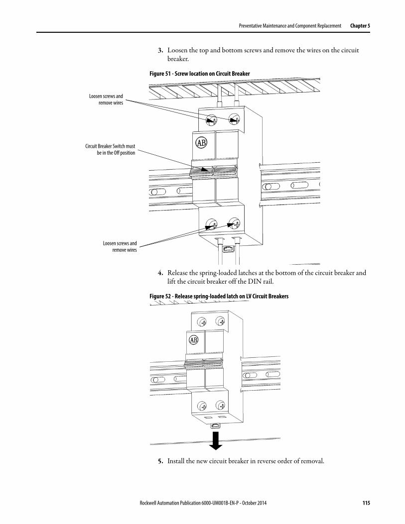
Preventative Maintenance and Component Replacement Chapter 5
3. Loosen the top and bottom screws and remove the wires on the circuit breaker.
Figure 51 - Screw location on Circuit Breaker
4. Release the spring-loaded latches at the bottom of the circuit breaker and lift the circuit breaker off the DIN rail.
Figure 52 - Release spring-loaded latch on LV Circuit Breakers
5. Install the new circuit breaker in reverse order of removal.
Circuit Breaker Switch mustbe in the Off position
Loosen screws andremove wires
Loosen screws andremove wires
Rockwell Automation Publication 6000-UM001B-EN-P - October 2014 115

Chapter 5 Preventative Maintenance and Component Replacement
Inspect Coils
If a coil exhibits evidence of overheating (cracked, melted or burned insulation), it must be replaced. In that event, check for and correct overvoltage or undervoltage conditions, which can cause coil failure. Be sure to clean any residue of melted coil insulation from other parts of the device or replace such parts.
Inspect Contacts
Check contacts for excessive wear and dirt accumulations. Vacuum or wipe contacts with a soft cloth if necessary to remove dirt. Contacts are not harmed by discoloration and slight pitting. Do not file contacts. Do not use contact spray cleaners as residues on magnet pole faces or in operating mechanisms can cause sticking and can interfere with electrical continuity. Replace contacts only after the contact face material is badly worn. Replace contacts in complete sets to avoid misalignment and uneven contact pressure.
Inspect Pilot Lights
Replace any burned out lamps or damaged lenses. Do not use solvents or cleaning agents on the lenses.
Do not use test equipment for solid-state controls which is not factory recommended. Doing so can result in damage to the control or test equipment, or unintended actuation of the controlled equipment.
Solid-state devices require little more than a periodic visual inspection. Replace discolored, charred, or burned components. Necessary replacements should be made only at the PC board or plug-in component level. Verify the printed circuit boards are seated in the edge board connectors. Board locking tabs should also be in place. Protect solid-state devices from contamination, and maintain appropriate cooling provisions. Do not use solvents on printed circuit boards.
Inspect Locking and Interlocking Devices
Check these devices to verify proper working condition. Make any necessary replacements only with Allen-Bradley renewal parts or kits. Adjust or repair only in accordance with Allen-Bradley instructions found in the product User Manuals.
116 Rockwell Automation Publication 6000-UM001B-EN-P - October 2014

Preventative Maintenance and Component Replacement Chapter 5
Connections
Inspect LV Component Terminal and Plug-in Connections
All LV control connections must be secure. Check for dirt, debris, or foreign material, and clean with anti-static cloth if necessary.
Check relays, contactors, timers, terminal connectors, circuit breakers, ribbon cables, control wires, etc. Check for corrosion, excessive temperature, or contamination. Clean all components using a vacuum cleaner.
Inspect Medium Voltage Cable Connections
Verify that all MV power cable connections and grounding cables are torqued to specification. Apply torque sealer where necessary. Check for corrosion, excessive temperature, or contamination.
Inspect Power Cable and Control Wire Terminals
Loose connections in power circuits can cause overheating that can lead to equipment malfunction or failure. Loose connections in control circuits can cause control malfunctions. Loose bonding or grounding connections can increase hazards of electrical shock and contribute to electromagnetic interference (EMI). Check the tightness of all terminals and bus bar connections and tighten securely any loose connections. Replace any parts or wiring damaged by overheating, and any broken wires or bonding straps. Refer to the User Manual for torque values required for power cable and bus hardware connections.
Inspect Transformer Secondary Windings
Check the Incoming Line Power Cable connections (L1, L2, and L3), the Outgoing Motor Power Cable connections (U, V, W), and the Isolation Transformer Power Cable Connections are torqued to specifications. See Figure 9 on page 19 and Figure 10 on page 19.
Inspect LV Component Terminal and Plug-in Connections 117
Inspect Medium Voltage Cable Connections 117
Inspect Power Cable and Control Wire Terminals 117
Inspect Transformer Secondary Windings 117
Inspect Power Module Input and Output Power Connections 118
Rockwell Automation Publication 6000-UM001B-EN-P - October 2014 117

Chapter 5 Preventative Maintenance and Component Replacement
Inspect the bus bars and cable connections. Check for any signs of overheating / discoloration and tighten the bus connections to the required torque specifications. Clean all cables and bus bars that exhibit dust build-up. Check for corrosion, excessive temperature, or contamination.
Inspect Power Module Input and Output Power Connections
Verify that all Power Module input line cables and output bus connections are properly torqued. Verify the output cables, VSB Cables and star connection cables are properly torqued. Apply torque sealer if required. Check for corrosion, excessive temperature, or contamination.
General Review Firmware and Hardware
Verify the firmware version on the HMI. Contact Rockwell Automation to determine whether there are any enhancements or changes made to the Drive Hardware and Control that would be valuable to the application.
Verify that the HMI is operational. Check the status indicators on the Control Unit in the LV Control Cabinet register as normal.
Remove any dirt or foreign material. Wipe components with an anti-static cloth, where applicable.
Inspect/Review Spare Parts
Check for signs of damage, dirt, or foreign material. See Spare Parts on page 127.
ATTENTION: Ensure there is no power to the drive and wear an anti-static wristband.
ATTENTION: Some circuit boards can be destroyed by static charges. Use of damaged circuit boards may also damage related components. Use a grounding wrist strap when handling sensitive circuit boards.
118 Rockwell Automation Publication 6000-UM001B-EN-P - October 2014

Appendix A
Technical Specifications
DescriptionPower Rating Range @ 3 kV motor voltage 320…1600 kW
Power Rating Range @ 3.3 kV motor voltage 360…1720 kW
Power Rating Range @ 6 kV motor voltage 200…3360 kW
Power Rating Range @ 6.6 kV motor voltage 220…3720 kW
Power Rating Range @ 10 kV motor voltage 200…5600 kW
Motor Type Induction (asynchronous) motors
Input Voltage Rating 3 kV, 3.3 kV, 6 kV, 6.6 kV, 10 kV, 11 kV
Input Voltage Tolerance ±10% of Nominal
Input Voltage Sag -20% of Nominal, duration – 60 seconds
Input Frequency 50/60 Hz, ±5%
Input Impedance Device Multiphase Isolation Transformer
Output Voltage 0…3000V, 0…3300V, 0…6000V, 0…6600V, 0…10,000V
Rectifier Configurations 18 pulse (3 kV, 3.3 kV), 36 pulse (6 kV, 6.6 kV), 54 pulse (10 kV, 11 kV)
Inverter Configuration Pulse Width Modulated (PWM) power modules
Power Semiconductors Diodes (rectifier), IGBTs (inverter)
Output Current THD (1st…49th) < 5%
Output Waveform to Motor Near Sinusoidal Current / Voltage
Medium Voltage Isolation Fiber Optic
Control Method Volts per hertz
Output Frequency Range 0.5…75 Hz
Acceleration/Deceleration time 0...3276 seconds
Flying Start Capability Yes
Service Duty Rating 120% Overload for 1 min every 10 min
Input Power Factor >.95
VFD Efficiency(1) >96.5%
VFD Noise Level < 80 dB
Operator Interface 7 in. WinCE Color Touchscreen
Languages English, Chinese
Control Power 120V 60 Hz, 240V 60 Hz, 110V 50 Hz, or 220V 50 Hz (3 kVA)
External Input Ratings 24V DC
External Output Ratings 240V AC/2 A
Analog Inputs (Optional) Four non-isolated, 4…20 mA or 0…10V DC (two spare)
Analog Outputs (Optional) Two isolated: 4…20 mA, two isolated: 0…5V DC (spare)
Communications Protocols (Optional) RS232/422/485, Modbus, Modbus Plus, Profibus DP, EtherNet I/P
Enclosure IP31 (standard), IP42 (optional)
Structure Finish Epoxy Powder - PaintExterior Sandtex Light Grey (RAL 7038) - Black (RAL 8022)Internal - Control Sub Plates - High Gloss White (RAL 9003)
Corrosion Protection Unpainted Parts (Zinc Plated / Bronze Chromate)
Ambient Temperature (Operating) 0…40 °C (standard), 0…50 °C (optional with derating)
Ambient Temperature (Storage) -25…55 °C
Relative Humidity Max. 95% non-condensing
Altitude 0…1000 m (standard)1001…3000 m (optional)
(1) Average for Product Portfolio.
Rockwell Automation Publication 6000-UM001B-EN-P - October 2014 119

Appendix A Technical Specifications
Notes:
120 Rockwell Automation Publication 6000-UM001B-EN-P - October 2014

Appendix B
Catalog Number Explanation
(4) A A A Drive Current Ratings shown are only for Normal Duty, 0...1000 m altitude, and 0...40 ºC ambient temperature. Not all drive current ratings are available in all voltages. Refer to the PowerFlex 6000 Selection Guide.
aBulletin Number
Code Description
6000 All Drive Products
bService Duty/Altitude/Ambient Temperature Code
Code Type
• •Service Duty (First Position)A: Normal DutyZ: Custom (Contact Factory)
• •Altitude (Second Position)A: 0...1000 m(1)
B: 1001...2000 m(2)
C: 2001...3000 m(2)
Z: Custom (Contact Factory)
(1) 0...1000 m (• A B) is the only valid altitude for 50 ºC, as a standard supported option.(2) Derating for altitude is 10% of the stated A A A Drive Current Rating for 1001...2000 m, and
20% of the stated A A A Drive Current Rating for 2001...3000 m.(3) Derating for ambient temperature is 2.5% of the stated A A A Drive Current Rating per degree
over 40 ºC.
• • Ambient Temperature (Third Position)A: 0...40 ºCB: 0...50 ºC (1)(3)
Z: Custom (Contact Factory)
cA A A Drive Current Rating(4)
Code Description Code Description
15 15 Amp 25 25 Amp
16 16 Amp 26 26 Amp
18 18 Amp 28 28 Amp
20 20 Amp 30 30 Amp
24 24 Amp 32 32 Amp
c (continued)A A A Drive Current Rating(4)
Code Description Code Description
33 33 Amp 112 112 Amp
36 36 Amp 120 120 Amp
40 40 Amp 125 125 Amp
41 41 Amp 138 138 Amp
45 45 Amp 140 140 Amp
48 48 Amp 150 150 Amp
50 50 Amp 160 160 Amp
54 54 Amp 168 168 Amp
56 56 Amp 180 180 Amp
60 60 Amp 192 192 Amp
63 63 Amp 200 200 Amp
66 66 Amp 225 225 Amp
71 71 Amp 250 250 Amp
75 75 Amp 280 280 Amp
80 80 Amp 300 300 Amp
84 84 Amp 315 315 Amp
90 90 Amp 350 350 Amp
96 96 Amp 380 380 Amp
100 100 Amp 420 420 Amp
108 108 Amp
Position
1 2 3 4 5 6 7 8 9
6000 A A A 41 M R 5 AL R 1...etc.a b c d e f g h i
Rockwell Automation Publication 6000-UM001B-EN-P - October 2014 121

Appendix B Catalog Number Explanation
(5) The only control voltage/frequency combinations available as a standard supported option are 110V/50 Hz, 220V/50 Hz, 120V/60 Hz, and 240V/60 Hz.
(6) Nominal line voltage equals nominal load voltage except for 11 kV line voltage, where 11 kV is NOT available as a load voltage. For 11 kV line voltage, the only valid load voltage options are 3.3 kV and 6.6 kV.
dEnclosure Type
Code Description
M IP31
W IP42
eNominal Line Voltage
Code Description
B 3.0 kV
C 3.3 kV
F 6.0 kV
J 6.6 kV
R 10 kV
S 11 kV
fLine Frequency
Code Description
5 50 Hz
6 60 Hz
gControl Voltage(5)
Code Description
AG 110V
AJ 120V
AL 220V
AP 240V
hNominal Load (Motor) Voltage(6)
Code Description
B 3.0 kV
C 3.3 kV
F 6.0 kV
J 6.6 kV
R 10 kV
iOptions
Refer to PowerFlex 6000 Medium Voltage Drives Options List.
Position
1 2 3 4 5 6 7 8 9
6000 A A A 41 M R 5 AL R 1...etca b c d e f g h i
122 Rockwell Automation Publication 6000-UM001B-EN-P - October 2014

Appendix C
Preventative Maintenance Schedule
PowerFlex 6000 Maintenance Schedule
This Annual Preventative Maintenance Program includes a visual inspection of all drive components visible from the front of the unit, power supply voltage level checks, general cleaning and maintenance, checking of all accessible power connections for tightness, and other tasks.
I – Inspection
This indicates that the component should be inspected for signs of excessive accumulation of dust/dirt/etc. or external damage.
M – Maintenance
This indicates a maintenance task that is outside the normal preventative maintenance tasks.
R – Replacement
This indicates that the component has reached its mean operational life, and should be replaced to decrease the chance of component failure. It is very likely that components will exceed the design life in the drive, and that is dependent on many factors such as usage, heating, etc.
C – Cleaning
This indicates the cleaning of a part that can be reused, and refers specifically to the door-mounted air filters.
Rv – Review
This refers to a discussion with Rockwell Automation to determine whether any of the enhancements/changes made to the Drive Hardware and Control would be valuable to the application.
RFB/R – Refurbishment/Replacement
The parts can be refurbished at lower cost OR the parts can be replaced with new ones.
Rockwell Automation Publication 6000-UM001B-EN-P - October 2014 123

Appendix C Preventative Maintenance Schedule
Table 8 - Preventative Maintenance Schedule (0...10 yrs.)
Interval Period (in years from commissioning date)
0 1 2 3 4 5 6 7 8 9 10Component Location
ComponentCategory
Component/Item
IsolationTransformerCabinet
Air-cooling system Door Mounted Air Filters C / R C / R C / R C / R C / R C / R C / R C / R C / R C / R C / R
Top-Mounted Main Cooling Fans
I I I I RFB/R I I I I RFB/R
Auxiliary Cooling Fans I I I R I I I R I I
Integral Magnetics Isolation Transformer I I I I I I I I I I
LV Control Isolation Transformer Temperature Monitor
I I I I I R I I I I
Voltage Sensing Board I I I I I I I I I I
Power Module Cabinet
Air-cooling system Door Mounted Air Filters C / R C / R C / R C / R C / R C / R C / R C / R C / R C / R C / R
Top Mounted Main Cooling Fans
I I I I RFB/R I I I I RFB/R
Power Module Electrolytic Capacitors(1) I I I I R I I I I I
Misc. HECS I I I I I I I I I I
LVControl Cabinet
Misc. AC/DC Power Supplies I I I I R I I I I I
UPS UPS I I I I I I I I I I
Batteries (UPS)(2) M M R M M R M M R M
LV Control PLC I I I I I I I I I I
Control Unit I I I I I I I I I I
HMI I I I I I I I I I I
LV Control Relays I I I I I I I I I I
LV Control Circuit Breakers I I I I I I I I I I
All Connections LV Component Terminal & Plug-in Connections
I I I I I I I I I I
Medium Voltage Cable Connections
I I I I I I I I I I
Transformer Secondary Winding Connections
I I I I I I I I I I
Power Module Input and Output Power Connections
I I I I I I I I I I
General Enhancements Firmware Rv Rv Rv Rv Rv Rv Rv Rv Rv Rv
Hardware — — Rv — — Rv — — Rv —
Operational Conditions
Parameters / Variables I I Rv I I Rv I I Rv I
Spare Parts Inventory Needs I I Rv I I Rv I I Rv I
(1) Power Modules are refurbished at factory as part of an exchange program.
(2) Fully discharge and recharge the UPS batteries every 6 months, to extend battery life.
124 Rockwell Automation Publication 6000-UM001B-EN-P - October 2014

Preventative Maintenance Schedule Appendix C
Table 9 - Preventative Maintenance Schedule (11...20 yrs.)
Interval Period (in years from commissioning date)
11 12 13 14 15 16 17 18 19 20Component Location
ComponentCategory
Component/Item
IsolationTransformerCabinet
Air-cooling system Door Mounted Air Filters C / R C / R C / R C / R C / R C / R C / R C / R C / R C / R
Top Mounted Main Cooling Fans
I I I I RFB/R I I I I I
Auxiliary Cooling Fans I R I I I R I I I R
Integral Magnetics Isolation Transformer I I I I I I I I I I
LV Control Isolation Transformer Temperature Monitor
I R I I I I I R I I
Voltage Sensing Board I I I I I I I I I I
Power Module Cabinet
Air-cooling system Door Mounted Air Filters C / R C / R C / R C / R C / R C / R C / R C / R C / R C / R
Top Mounted Main Cooling Fans
I I I I RFB/R I I I I I
Power Module Electrolytic Capacitors(1) R I I I I I R I I I
Misc. HECS I I I I I I I I I I
LVControl Cabinet
Misc. AC/DC Power Supplies R I I I I I R I I I
UPS UPS I I I I I I I I I I
Batteries (UPS)(2) M R M M R M M R M M
LV Control PLC I I I I I I I I I I
Control Unit I I I I I I I I I I
HMI I I I I I I I I I I
LV Control Relays I I I I I I I I I I
LV Control Circuit Breakers I I I I I I I I I I
All Connections LV Component Terminal & Plug-in Connections
I I I I I I I I I I
Medium Voltage Cable Connections
I I I I I I I I I I
Transformer Secondary Winding Connections
I I I I I I I I I I
Power Module Input and Output Power Connections
I I I I I I I I I I
General Enhancements Firmware Rv Rv Rv Rv Rv Rv Rv Rv Rv Rv
Hardware — Rv — — Rv — — Rv — —
Operational Conditions
Parameters / Variables I Rv I I Rv I I Rv I I
Spare Parts Inventory Needs I Rv I I Rv I I Rv I I
(1) Power Modules are refurbished at factory as part of an exchange program.
(2) Fully discharge and recharge the UPS batteries every 6 months, to extend battery life.
Rockwell Automation Publication 6000-UM001B-EN-P - October 2014 125

Appendix C Preventative Maintenance Schedule
Notes:
126 Rockwell Automation Publication 6000-UM001B-EN-P - October 2014

Appendix D
Spare Parts
Spare Parts ListPart Number Part Description Repair Replace
H5JZ-065-276-R Power Module Control Board 315
H5JZ-065-269-R DB Board, Ver. 1.0.0
H5JZ-065-271-01-R Control Unit Digital Signal Processor Board (H5JZ-065-271-01)
H5JZ-065-270-R Control Unit Analog Signal Processor Board (Version 1.0.0)
H5JZ-065-272-01-R CPU Board (H5JZ-065-272-01)
H5JZ-065-277-01-R PWM Board (H5JZ-065-277-01)
H5JZ.065.152-R 1200V HV DC-DC BAR-TYPE Board Assembly
H5JZ.065.065-R HMI Communication Board Assembly
H5JZ-065-032-R Power Module Balance Board Assembly
H3M45014-3.0KV-R 3 kV Voltage Sensing Board Assembly
H3M45014-R 6 kV Voltage Sensing Board Assembly
H3M45048-R 10 kV Voltage Sensing Board Assembly
H02040199-01-R Control Unit (H02040199-01), (including all boards)
H01012343-R Control Unit Enclosure
HTPUXX/030-AC3-R 30 Amp Power Module
HTPUXX/040-AC3-R 40 Amp Power Module
HTPUXX/050-AC3-R 50 Amp Power Module
HTPUXX/060-AC3-R 60 Amp Power Module
HTPUXX/075-AC3-R 75 Amp Power Module
HTPUXX/080-AC3-R 80 Amp Power Module
HTPUXX/100-AC3-R 100 Amp Power Module
HTPUXX/120-AC3-R 120 Amp Power Module
HTPUXX/150-AC3-R 150 Amp Power Module
HTPUXX/180-AC3-R 180 Amp Power Module
HTPUXX/200-AC3-R 200 Amp Power Module
HTPUXX/300-AC3-R 300 Amp Power Module
HTPUXX/380-AC3-R 380 Amp Power Module
HTPUXX/420-AC3-R 420 Amp Power Module
2711-T7C4D9 PanelView Plus 6 HMI
HRH40M-50-60-R 50/60HZ Centrifugal Fan RH40M
HRH45M-50-60-R 50/60HZ Centrifugal Fan RH45M
H01020062-R Door Filter (005 BK 25P P2 1700*1000*10)
HFL-000090-R Standby Fiber (Plug) T -R 5 Meters
Rockwell Automation Publication 6000-UM001B-EN-P - October 2014 127

Appendix D Spare Parts
H01220097-R UPS KR1000 1000VAH-AC220V I/O
H01200077-R Hall Effect Current Sensor CHF (100G 100A-15V-5V-D35)
H01200078-R Hall Effect Current Sensor CHF (200G 200A-15V-5V-D35)
H01200079-R Hall Effect Current Sensor CHF (300G 300A-15V-5V-D35)
HDQ-000015-R Hall Effect Current Sensor CHF (400G 400A-15V-5V-D35)
H01200112-R Hall Effect Current Sensor CHF (500G 500A-15V-5V-D35)
H0109010169-R Fuse RGS7-700V-63A
H0109010163-R Fuse RGS7-700V-80A
H0109010164-R Fuse RGS7-700V-100A
H0109010170-R Fuse RGS7-700V-125A
H0109010165-R Fuse RGS7-700V-160A
H01340697-R Fuse RGS7-700V-200A
H01340698-R Fuse RGS7-700V-250A
H0109020029-R Fuse RS98E-700V-350A
H0109020099-R Fuse RS98G-700V-500A
H5JZ-065-234-R IGBT FF450R17ME3 drive board assembly
H5JZ-065-235-R IGBT module FS450R17KE3 drive interface board
Part Number Part Description Repair Replace
128 Rockwell Automation Publication 6000-UM001B-EN-P - October 2014

Appendix E
Torque Requirements
Torque Requirements Proper tightening torque must be used for installation and wiring. Table 10 - Torque Requirements
Thread SizeTorque
N•m lb•ft
M4 1.4 1.0
M5 2.8 2.1
M6 4.6 3.4
M8 11 8.1
M10 22 16.2
M12 39 28.8
M14 62 45.7
M16 95 70.1
M20 184 135.7
Rockwell Automation Publication 6000-UM001B-EN-P - October 2014 129

Appendix E Torque Requirements
Notes:
130 Rockwell Automation Publication 6000-UM001B-EN-P - October 2014

Index
AAC/DC Power Supplies 101
Check Output Voltage 101Inspect 101Maintenance Schedule 124Replace 102Replace G1 102Replace G2 102Replace G3 103
Acc Time 39Accel 35
Function 37Actual Frequency 35Additional Resources 7Air Filters 81
Clean 81Location 81Replace 81
AlarmAcc Time 39Code 39History 39List 64Message 39QTY 39Reset Alarm 39Reset Status 39Sort 40
Alarm History 40Alarm Status 39Allowed 34Altitude 121Ambient Air Temperature 10Ambient Temperature Code 121Analog Signal Processor Board (AT) 30Auto Bypass 49
BBatteries
Disposal 107Battery
Replace UPS Batteries 106Bulletin Number 121Button Function
Alarm 34Home 34Operation 34Settings 34Trends 34
Bypass ContactorOpen/Close 47
Bypass ModeAuto Bypass 49Manual Bypass 49No Bypass 49
CCatalog Number Explanation 121Close Bypass Contactor 47Close Drive Input Contactors 46Close Drive Output Contactors 46Code 39Coils
Maintenance 116Commissioning Support 8Confirm Bypass Mode 43Connect 34Connectivity Overview 13Control Board
Hardware 109Replace 109
Control Unit 30Analog Signal Processor Board 30Component Layout 30CPU Board 30Description 30Digital Signal Processor Board (DT) 30Fiber Optic Socket Location 30Function Summary 30Hardware 109HMI Communication Interface Location 30Inspect 108Interface Terminals 30Maintenance Schedule 124Part Description 31PWM Board A 30PWM Board B 30PWM Board C 30Replace 108Replace Control Board 109Schematic 31
Control Voltage 122CPU Board 30Current Trends 42Current User
User 50
DDB Board
Control UnitDB Board 30
Decel 35Function 37
Digital Signal Processor Board (DT) 30Door Mounted Air Filters
Maintenance Schedule 124Door Position Limit Switch
Inspect 88Drawount Power Module
Basic Principles 26
Rockwell Automation Publication 6000-UM001B-EN-P - October 2014 131
Index
Drawout Power ModuleCatalog Number 28Configuration 25Dimensions 91Lift Cart 93Locking Key 96Low Voltage Power Module 26Output Rating 91Replace 93, 95Replace Fuse 98Spare Part NumberDrawout Power Module
Current Rating 28Weight 91
Drive Current Rating 121Drive Input Contactors
Close 46Open 46
Drive Output ContactorsClose 46Open 46
Drive Setup and Configuration Controls 34
EElevation 10Elevation Drawings 17
Drawout Power Module Configuration 18Fixed-mounted Power Module Configuration
17Enclosure Type 122Environmental Conditions 10
Ambient Air Temperature 10Elevation 10IEC721-1 10
FFirmware
Maintenance Schedule 124Firmware Version 38Fixed-mounted Power Module
Basic Principles 26Catalog Number 28Components 27, 91Configuration 25Current Rating 28Dimensions 91Fuse Location 27Hardware 91Line Terminal Location 27Low Voltage Power Module 26Output Rating 91Output Terminal Location 27Replace 91Replace Fuse 97Spare Part Number 28Specifications 91Weight 91
Frequency Trends 42
FuseDrawout Power Module Fuse Hardware 98Fixed-Mounted Power Module Fuse Hardware
97Replace Drawout Power Module 98Replace Fixed-mounted Power Module 97
GG1 Power Supply
Location 101Replace 102
G2 Power SupplyLocation 101Replace 102
G3 Power SupplyLocation 101Replace 103
General Precautions 8Guardmaster Safety Limit Switch 23
HHECS
Hardware 99Inspect 99Maintenance Schedule 124Mounting Bracket 100Replace 99
HistoryAlarm 39
132 Rockwell Automation Publication 6000-UM001B-EN-P - October 2014

Index
HMI24V Power Supply 112Acc Time 39Additional Information 112Alarm 34Alarm History 40Alarm Status 39Change Interface Language 48Change P Parameters 53Change Parameters 50Change T Parameters 53Choose Local/Remote Operation 45Code 39Configuration Controls 34Confirm Bypass Mode 43Connect 34Current Trends 42Data Cable 112Drive Setup Controls 34EtherNet/IP 112Firmware 118Frequency Trends 42Ground Cable 112Home 34Local 34Maintenance Schedule 124Message 39MVClsd 34Open/Close Bypass Contactor 47Open/Close Drive Input Contactors 46Open/Close Drive Output Contactors 46Operation 34Operation Bar 35Operation Layout 43Overview 33QTY 39Ready 34Remote 34Restore P Parameters 55Restore T Parameters 55Running 34Select Bypass Mode 49Set Frequency 36Settings 34, 48Setup and Monitor Box 35Sort Alarms 40Status Indicators 34Trend Selection 41Trends 34, 41User Login 50Version Information 38Voltage Trends 42Warning 34
IIEC721-1 10Incoming Line Power Cable Connection
Location 19
Isolation Transformer3-phase Primary Coils 20Auxiliary Cooling Fans 22Clean/Replace Air Filters 81Fan Balance 84Inspect 86Inspect Secondary Windings 117Location 19Maintenance Schedule 124Power Cabling Overview 24Primary Winding Voltage Rating 20Replace HECS 99Replace Isolation Transformer Auxiliary
Cooling Fan 86Replace Voltage Sensing Board 87Secondary Winding Voltage 20Temperature Monitor 21Top Mounted Main Cooling Fans 82Voltage Sensing Board 24
Isolation Transformer Auxiliary Cooling Fan 85Circuit Breaker Location 85Hardware 86Inspect 85Replace 86Test 85
Isolation Transformer Auxiliary Cooling Fans 19, 22
Maintenance Schedule 124Isolation Transformer Cabinet
Drawout Power Module Drive Configuration Components 19
Layout 19Isolation Transformer LV Door
Temperature Monitor 21Isolation Transformer MV Door Safety
Interlock 23Isolation TransformerReplace
Top Mounted Main Cooling Fans 83
LLanguage
Change HMI Language 48LC Control Cabinet
Circuit Breaker Location 104Replace UPS 105UPS 104
Lift Cart 93Operation 93
Line Frequency 122Local 34Local Operation 45Lockout and tagout 9Login 50
Setup 53
Rockwell Automation Publication 6000-UM001B-EN-P - October 2014 133

Index
LV Control Cabinet 29AC/DC Power Supplies 101Component Layout 29HMI Firmware 118Inspect PLC 108LV Control Circuit Breakers Hardware 115LV Control Relay Hardware 113Replace AC/DC Power Supplies 102Replace Control Boards 108Replace Control Unit 108Replace G1 AC/DC Power Supply 102Replace G2 AC/DC Power Supply 102Replace G3 AC/DC Power Supply 103Replace LV Control Circuit Breakers 114Replace LV Control Relay 113Replace the HMI
HMIReplace 111
Replace UPS Batteries 106Test UPS Battery Voltage 107
LV Control Circuit BreakersHardware 115Location 114Replace 114
LV Control RelayHardware 113Location 113Replace 113
LV Control RelaysMaintenance Schedule 124
LV Control Unit 30
MMain Interface
Screen Layout 33Maintenance 77
Inspect Power Connection 79Inspect Power Module Input Connections 118Inspect Power Module Output Power
Connections 118Isolation Transformer Secondary Windings
117LV Component Terminals 117MV Connections 117Physical Checks 79Regular 78Report 80Schedule 123
Manual Bypass 49Medium Voltage Cable Connections
Maintenance Schedule 124Monitoring Parameters Display 35Motor Current 35Motor Speed 35Motor Voltage 35Mounting Bracket, HECS 100MV Door Safety Interlock 23
Location 23MVClsd 34
NNominal Line Voltage 122Nominal Load (Motor) Voltage 122
OOpen Bypass Contactor 47Open Drive Input Contactors 46Open Drive Output Contactors 46Operation
Layout 43Operation Bar
Accel 35Decel 35Reset 35Start 35Stop 35
Outgoing Motor Power Cable ConnectionsLocation 19
Output VoltageAC/DC Power Supplies 101
PP Parameters
Restore 55Parameter Access Level
Setup Settings 53Parameters
Change 50Physical Maintenance Checks 79
Inspect Power Connections 79Pilot Lights
Maintenance 116PLC 32
Additional Information 108Components 32Inspect 108Maintenance Schedule 124
Power ModuleInspect Input Power Connections 118Inspect Output Power Connections 118Replace Drawout Power Module 93Replace Fixed-mounted Power Module 91
Power Module Cabinet 25Clean/Replace Air Filters 81Drawout Power Module Configuration 25Fan Balance 84Fixed-mounted Power Module Configuration
25Power Cabling Overview 24Replace HECS 99Replace Isolation Transformer Auxiliary
Cooling Fan 86Replace Top Mounted Main Cooling Fans 83Top Mounted Main Cooling Fans 82
134 Rockwell Automation Publication 6000-UM001B-EN-P - October 2014
Index
PowerFlex 6000Altitude Rating 121Ambient Temperature Code 121Bulletin Number 121Catalog Number Explanation 121Drive Current Rating 121Elevation Drawings 17, 18Enclosure Type 122Firmware Version 38Isolation Transformer Cabinet 18Isolation Transformer Cabinet Layout 19Line Frequency 122Maintenance Schedule 123Nominal Line Voltage 122Nominal Load (Motor) Voltage 122Power Cabling Overview 24Service Duty 121Technical Specifications 119Torque Requirements 129
Principal Components 14Pulse Width Modulation 11
QQTY 39
RR&D Settings
Function 48Ready 34Remote 34Remote Operation 45Reset 35
Function 37Reset Alarm 39Running 34
SSafety Door Switches
Location 19Secondary Windings
Inspect 117Service and Support 8Service Duty 121Set Frequency 35, 36Settings
Overview 48R&D Settings 48Setup Settings 48System Settings 48User Settings 48
Setup and Monitor Box 35Actual Frequency 35Motor Current 35Motor Speed 35Motor Voltage 35Set Frequency 35
Setup Login 53
Setup SettingsChange P Parameters 53Change T Parameters 53Function 48P Parameters 53T Parameters 53
Simplified Electrical Diagrams 1210,000V (54 Pulse - 27 Power Modules) 123000V/3300V (18 Pulse - 9 Power Modules)
126000V/6600V (36 Pulse - 18 Power Modules)
12Spare Parts 127
Inspect 118Standards Compliance 15
16GB 10233.2005 16GB 12668.4-2006 16GB 12668.701-2013 16GB 156-2007 15GB 2682 15GB 3797-2005 15GB 4208-2008 15GB 7678-87 15GB/ 13422-2013 16GB/T 12668.4-2006 16GB/T 14549-93 15GB/T 15139-94 16GB/T 16935.1-2008 15GB/T 1980-2005 15GB/T 2423.10 15GB/T 2681 15GB/T 2900.18-2008 15GB/T 3859.1-2013 15GB/T 3859.2-2013 15GB/T 3859.3-2013 15GB/T 4588.1-1996 15GB/T 4588.2-1996 15GB1094.11 -2007 16IEC 106, 1989 15IEC 60038, 1983 15IEC 60050-151, 2001 15IEC 60050-551, 1999 15IEC 60076 15IEC 60146 15IEC 60721-3-1, 1997 15IEC 60721-3-2, 1997 15IEC 60721-3-3, 2008 15IEC 60757-1983 15IEC 61000-2-4, 2002 15IEC 61000-4-7, 2002 15IEC 61508.1-7 15IEC 61800-3, 2004 15IEC 61800-4, 2004 15IEEE 519 15IEEE 519-1992 16
Start 35Function 37
Stop 35Function 37
System SettingsFunction 48
Rockwell Automation Publication 6000-UM001B-EN-P - October 2014 135
Index
TT Parameters
List 63Restore 55
Technical Specifications 119Temperature Monitor 21
Layout 21User Manual 21
Top Mounted Main Cooling FanHardware 83
Top Mounted Main Cooling FansFan Balance 84Inspect 82Replace 83
Top-mounted Main Cooling Fan 22Location 19
Top-mounted Main Cooling Fans 28Maintenance Schedule 124
Topology 10Connectivity Overview 13Pulse Width Modulation 11Typical Power Structure 11
Torque Requirements 129Transformer Secondary Winding Connections
Maintenance Schedule 124Trends 41
Scroll Controls 41Typical Power Structure 11
UUPS 32
Enclosure 106Front Display 105Inspect 104LV Circuit Breaker Location 104Maintenance Schedule 124Mounting Bracket 107Replace 105Replace Batteries 106Test Battery Output Voltage 107
UPS BatteriesMaintenance Schedule 124
User Login 50User Parameter Settings 51
Change 51User Settings
Function 48
VVersion Information 38
Screen Layout 38
Voltage Sensing Board 19, 24Hardware 88Inspect 87Insulation Board 87Location (Drawout Power Module
Configuration) 19Location (Fixed-mounted Configuration) 19Maintenance Schedule 124Power Cabling Overview 24Replace 87
Voltage Trends 42
WWarning 34
136 Rockwell Automation Publication 6000-UM001B-EN-P - October 2014


Publication 6000-UM001B-EN-P - October 2014 Copyright © 2014 Rockwell Automation, Inc. All rights reserved. Printed in Canada.
Rockwell Automation Support
Rockwell Automation provides technical information on the Web to assist you in using its products. At http://www.rockwellautomation.com/support, you can find technical manuals, technical and application notes, sample code and links to software service packs, and a MySupport feature that you can customize to make the best use of these tools. You can also visit our Knowledgebase at http://www.rockwellautomation.com/knowledgebase for FAQs, technical information, support chat and forums, software updates, and to sign up for product notification updates.
For an additional level of technical phone support for installation, configuration, and troubleshooting, we offer TechConnectSM support programs. For more information, contact your local distributor or Rockwell Automation representative, or visit http://www.rockwellautomation.com/support/.
Installation Assistance
If you experience a problem within the first 24 hours of installation, review the information that is contained in this manual. You can contact Customer Support for initial help in getting your product up and running.
New Product Satisfaction Return
Rockwell Automation tests all of its products to help ensure that they are fully operational when shipped from the manufacturing facility. However, if your product is not functioning and needs to be returned, follow these procedures.
Documentation Feedback
Your comments will help us serve your documentation needs better. If you have any suggestions on how to improve this document, complete this form, publication RA-DU002, available at http://www.rockwellautomation.com/literature/.
United States or Canada 1.440.646.3434
Outside United States or Canada Use the Worldwide Locator at http://www.rockwellautomation.com/rockwellautomation/support/overview.page, or contact your local Rockwell Automation representative.
United States Contact your distributor. You must provide a Customer Support case number (call the phone number above to obtain one) to your distributor to complete the return process.
Outside United States Please contact your local Rockwell Automation representative for the return procedure.
Medium Voltage Products, 135 Dundas Street, Cambridge, ON, N1R 5X1 Canada, Tel: (1) 519.740.4100, Fax: (1) 519.623.8930Online: www.ab.com/mvb
Allen-Bradley, Rockwell Software, Rockwell Automation, and TechConnect are trademarks of Rockwell Automation, Inc.
Trademarks not belonging to Rockwell Automation are property of their respective companies.