Embed Size (px)
Citation preview
1
4 - 1© P. Raatikainen Switching Technology / 2003
Switch Fabrics
Switching Technology S38.165http://www.netlab.hut.fi/opetus/s38165
4 - 2© P. Raatikainen Switching Technology / 2003
Switch fabrics
• Basic concepts• Time and space switching
• Two stage switches• Three stage switches• Cost criteria• Multi-stage switches and path search
2
4 - 3© P. Raatikainen Switching Technology / 2003
Cost criteria for switch fabrics
• Number of cross-points• Fan-out• Log ical depth• Blocking p robabili ty• Complexity of swi tch control• Total number of conn ection states• Path search
4 - 4© P. Raatikainen Switching Technology / 2003
Cross-points
• Number of cross-points gives the number of on-off gates(usually “ and-gates” ) in space switching equivalent of a fabric
• minimization of cross-point count is essential when cross-pointtechnology is expensive (e.g. electro-mechanical and opticalcross-points)
• Very Large Scale Integration (VLSI) technology implementscross-point complexity in Integrated Circuits (ICs)=> more relevant to minimize number of ICs than number ofcross-points
• Due to increasing switching speeds, large fabric constructionsand increased integration density of ICs, power consumption hasbecome a crucial design criteria- higher speed => more power- large fabrics => long buses, fan-out problem and more driving power- increased integration degree of ICs => heating problem
3
4 - 5© P. Raatikainen Switching Technology / 2003
Fan-out and logical depth
• VLSI chips can hide cross-point complexity, but introducepin count and fan-out problem
• length of interconnections between ICs can be long loweringswitching speed and increasing power consumption
• parallel processing of switched signals may be limited by thenumber of available pins of ICs
• fan-out gives the driving capacity of a switching gate, i.e. numberof inputs (gates/cross-points) that can be connected to an output
• long buses connecting cross-points may lower the number of gatesthat can be connected to a bus
• Logical depth gives the number of cross-points a signaltraverses on its way through a switch
• large logical depth causes excessive delay and signal deterioration
4 - 6© P. Raatikainen Switching Technology / 2003
Blocking probability
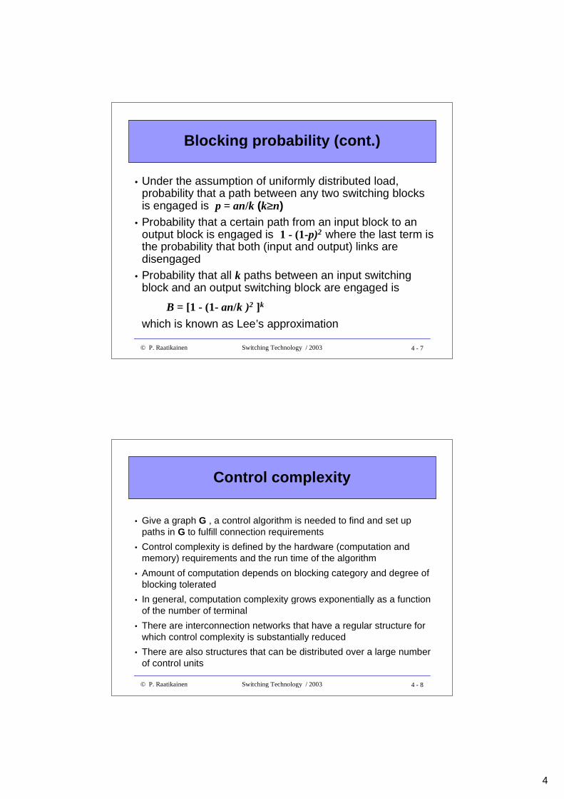
• Blocking probability of a multi-stage switching networkdifficult to determine
• Lee’s approximation gives a coarse measure of blocking• Assume uniformly distributed load
• equal load in each input• load distributed uniformly among
intermediate stages (and theiroutputs) and among outputsof the switch
• Probability that an input isengaged is a = = λλS where- λ = input rate on an input link- S = average holding time of a link
kxn
nxk
2
1
...
k
1
n
1
n
4
4 - 7© P. Raatikainen Switching Technology / 2003
Blocking probability (cont.)
• Under the assumption of uniformly distributed load,probability that a path between any two switching blocksis engaged is p = an/k (k≥≥n)
• Probability that a certain path from an input block to anoutput block is engaged is 1 - (1-p)2 where the last term isthe probability that both (input and output) links aredisengaged
• Probability that all k paths between an input switchingblock and an output switching block are engaged is
B = [1 - (1- an/k )2 ]k
which is known as Lee’s approximation
4 - 8© P. Raatikainen Switching Technology / 2003
Control complexity
• Give a graph G , a control algorithm is needed to find and set uppaths in G to fulfill connection requirements
• Control complexity is defined by the hardware (computation andmemory) requirements and the run time of the algorithm
• Amount of computation depends on blocking category and degree ofblocking tolerated
• In general, computation complexity grows exponentially as a functionof the number of terminal
• There are interconnection networks that have a regular structure forwhich control complexity is substantially reduced
• There are also structures that can be distributed over a large numberof control units
5
4 - 9© P. Raatikainen Switching Technology / 2003
Management complexity
• Network management involves adaptation and maintenance of aswitching network after the switching system has been put in place
• Network management deals with• failure events and growth in connectivity demand• changes of traffic patterns from day to day• overload situations• diagnosis of hardware failures in switching system, control system
as well as in access and trunk network- in case of failure, traffic is rerouted through redundant built-inhardware or via other switching facilities- diagnosis and failure maintenance constitute a significant part ofsoftware of a switching system
• In order for switching cost to grow linearly in respect to total traffic,switching functions (such as control, maintenance, call processing andinterconnection network) should be as modular as possible
4 - 10© P. Raatikainen Switching Technology / 2003
Example 1
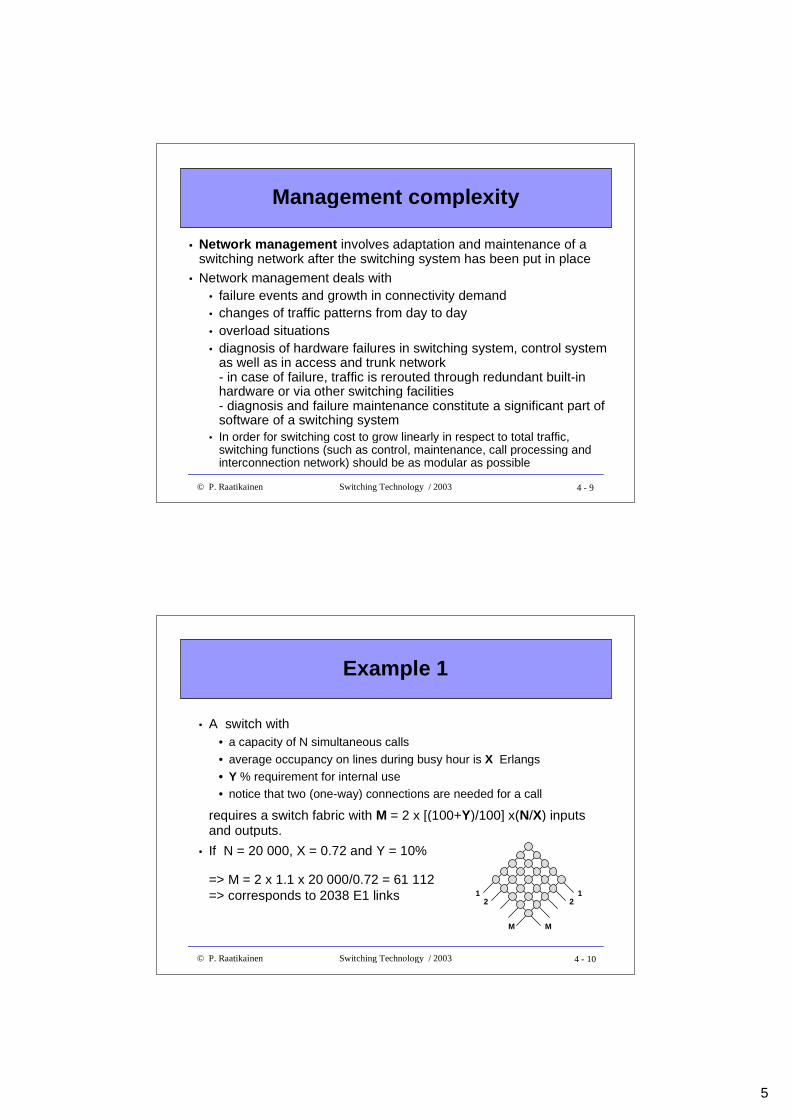
• A switch with• a capacity of N simultaneous calls
• average occupancy on lines during busy hour is X Erlangs• Y % requirement for internal use• notice that two (one-way) connections are needed for a call
requires a switch fabric with M = 2 x [(100+Y)/100] x(N/X) inputsand outputs.
• If N = 20 000, X = 0.72 and Y = 10%
=> M = 2 x 1.1 x 20 000/0.72 = 61 112=> corresponds to 2038 E1 links 1
2
M
12
M
6
4 - 11© P. Raatikainen Switching Technology / 2003
Amount of traff ic in Erlangs
• Erlang defines the amount of traffic flowing through acommunication system - it is given as the aggregate holding time ofall channels of a system divided by the observation time period
• Example 1:- During an hour period three calls are made (5 min, 15 min and 10min) using a single telephone channel => the amount of trafficcarried by this channel is (30 min/60 min) = 0.5 Erlang
• Example 2:- a telephone exchange supports 1000 channels and during a busyhour (10.00 - 11.00) each channel is occupied 45 minutes on theaverage => the amount of traffic carried through the switch duringthe busy hour is (1000x45 min / 60 min) = 75 Erlangs
4 - 12© P. Raatikainen Switching Technology / 2003
Erlang’s first formula
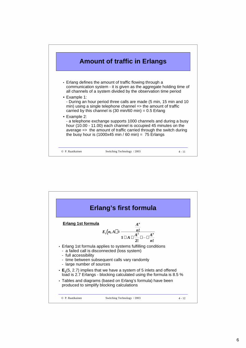
• Erlang 1st formula applies to systems fulfilling conditions- a failed call is disconnected (loss system)- full accessibility- time between subsequent calls vary randomly- large number of sources
• E1(5, 2.7) implies that we have a system of 5 inlets and offeredload is 2.7 Erlangs - blocking calculated using the formula is 8.5 %
• Tables and diagrams (based on Erlang’s formula) have beenproduced to simplify blocking calculations
(( ))E n A
An
AA A
n
n
n1 2
12
, !
! !
==++ ++ ++ ++�
Erlang 1st formula
7
4 - 13© P. Raatikainen Switching Technology / 2003
Example 2
• An exchange for 2000 subscribers is to be installed and it isrequired that the blocking probability should be below 10 %.If E2 links are used to carry the subscriber traffic totelephone network, how many E2 links are needed ?- average call lasts 6 min- a subscriber places one call during a 2-hour busy period(on the average)
• Amount of offered traffic is (2000x6 min /2x60 min) = 100 Erl.
• Erlang 1st formula gives for 10 % blocking and load of 100 Erl.that n = 97=> required number of E1 links is ceil(97/30) = 4
4 - 14© P. Raatikainen Switching Technology / 2003
Example 3
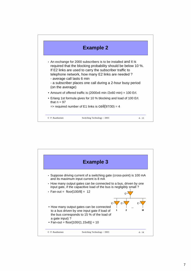
• Suppose driving current of a switching gate (cross-point) is 100 mAand its maximum input current is 8 mA
• How many output gates can be connected to a bus, driven by oneinput gate, if the capacitive load of the bus is negligibly small ?
• Fan-out = floor[100/8] = 12 c
c c c
1…
2 M• How many output gates can be connected
to a bus driven by one input gate if load ofthe bus corresponds to 15 % of the load ofa gate input) ?
• Fan-out = floor[100/(1.15x8)] = 10
8
4 - 15© P. Raatikainen Switching Technology / 2003
Switch fabrics
• Basic concepts• Time and space switching
• Two stage switches• Three stage switches• Cost criteria
• Multi-stage switches and path search
4 - 16© P. Raatikainen Switching Technology / 2003
Multi-stage switching
• Large switch fabrics could be constructed by using asingle NxN crossbar, interconnecting N inputs to Noutputs- such an array would require N2 cross-points- logical depth = 1- considering the limited driving power of electronic or opticalswitching gates, large N means problems with signal quality (e.g.delay, deterioration)
• Multi-stage structures can be used to avoid aboveproblems
• Major design problems with multi-stages- find a non-blocking structure- find non-conflicting paths through the switching network
9
4 - 17© P. Raatikainen Switching Technology / 2003
Multi-stage switching (cont.)
• Let’s take a network of K stages• Stage k (1≤k≤K) has rk switch blocks (SB)• Switch block j (1≤j≤ rk) in stage k is denoted by S(j,k)• Switch j has mk inputs and nk outputs• Input i of S(j,k) is represented by e(i,j,k)• Output i of S(j,k) is represented by o(i,j,k)• Relation o(i,j,k)= e(i’,j’,k+1) gives interconnection between output i
and input i’ of switch blocks j and j’ in consecutive stages k and k+1• Special class of switches:
• nk = rk+1 and mk = rk-1
• each SB in each stage connected to each SB in the next stage
4 - 18© P. Raatikainen Switching Technology / 2003
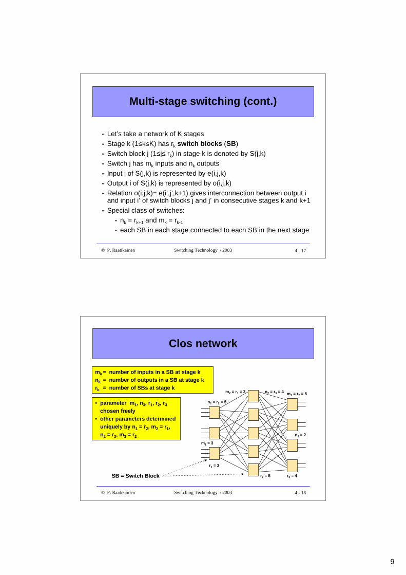
Clos network
• parameter m1, n3, r1, r2, r3
chosen freely• other parameters determined
uniquely by n1 = r2, m2 = r1,n2 = r3, m3 = r2
mk = number of inputs in a SB at stage knk = number of outputs in a SB at stage krk = number of SBs at stage k
SB = Switch Block
m1 = 3
n1 = r2 = 5
m2 = r1 = 3 n2 = r3 = 4 m3 = r2 = 5
r1 = 3
r3 = 4r2 = 5
n3 = 2
10
4 - 19© P. Raatikainen Switching Technology / 2003
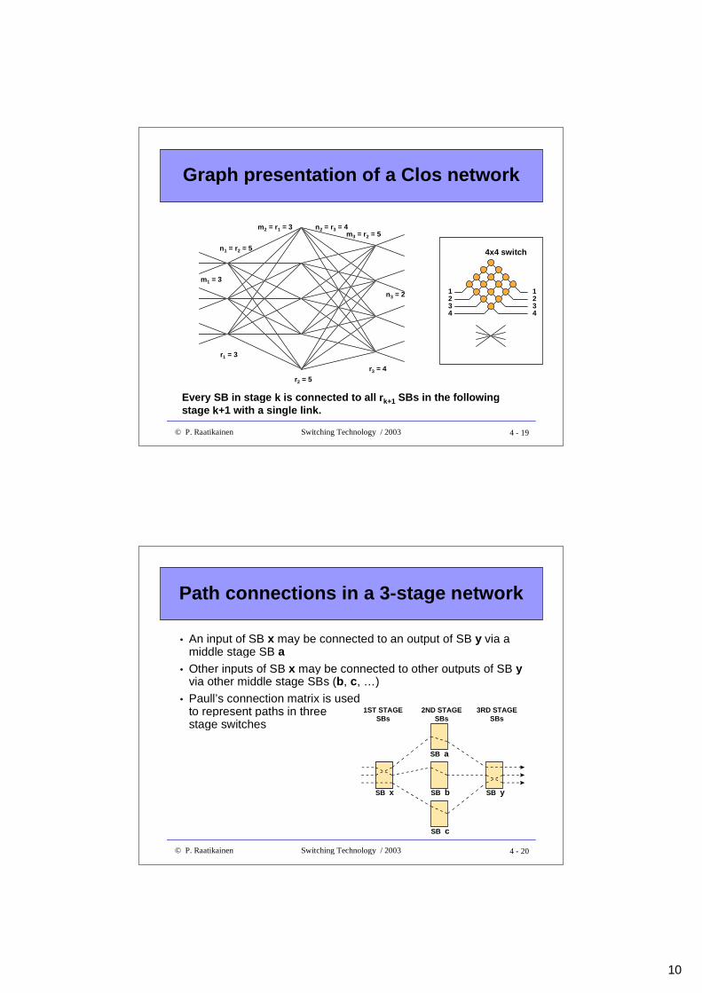
Graph presentation of a Clos network
n3 = 2
r1 = 3
r2 = 5r3 = 4
n1 = r2 = 5
m2 = r1 = 3 n2 = r3 = 4m3 = r2 = 5
m1 = 3
Every SB in stage k is connected to all rk+1 SBs in the followingstage k+1 with a single link.
1234
1234
4x4 switch
4 - 20© P. Raatikainen Switching Technology / 2003
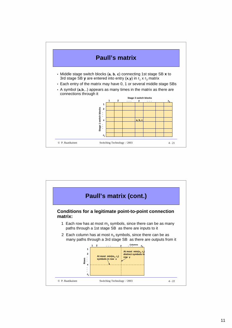
Path connections in a 3-stage network
1ST STAGESBs
SB a
2ND STAGESBs
3RD STAGESBs
SB b
SB c
SB x SB y
• An input of SB x may be connected to an output of SB y via amiddle stage SB a
• Other inputs of SB x may be connected to other outputs of SB yvia other middle stage SBs (b, c, …)
• Paull’s connection matrix is usedto represent paths in threestage switches
11
4 - 21© P. Raatikainen Switching Technology / 2003
Paull’s matrix
a, b, c
r3y1 2 . . . . . .
1
2
. . .
x
r1
. . .
Sta
ge
1 sw
itch
blo
cks
Stage 3 swi tch blocks
• Middle stage switch blocks (a, b, c) connecting 1st stage SB x to3rd stage SB y are entered into entry (x,y) in r1 x r3 matrix
• Each entry of the matrix may have 0, 1 or several middle stage SBs• A symbol (a,b,..) appears as many times in the matrix as there are
connections through it
4 - 22© P. Raatikainen Switching Technology / 2003
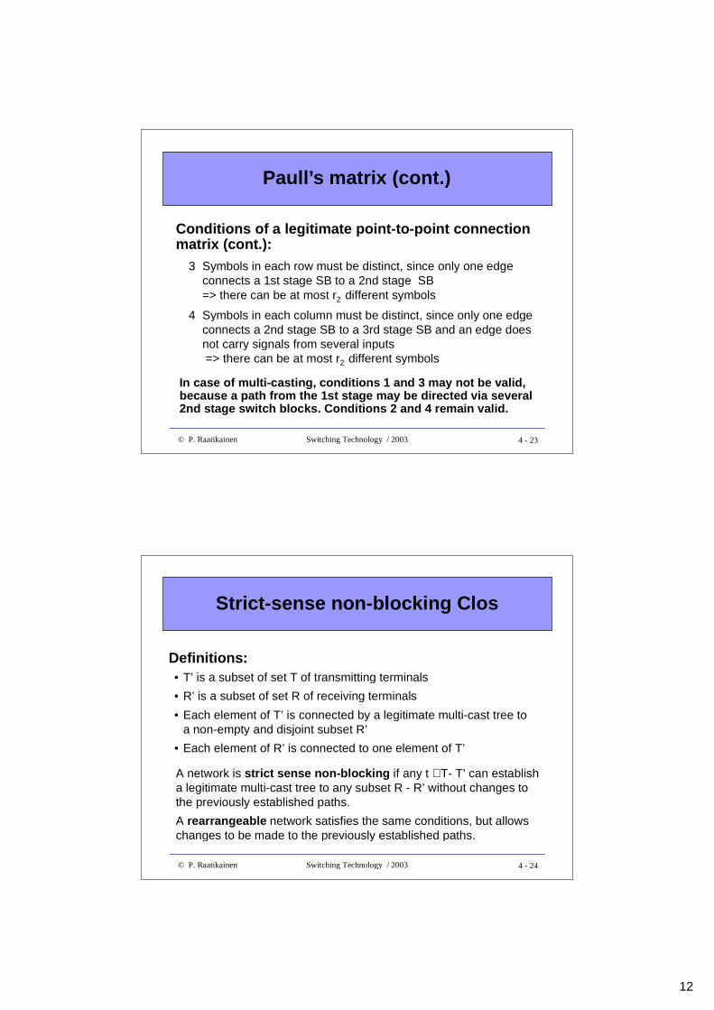
Paull’s matrix (cont.)
Conditions for a legitimate point-to-point connectionmatrix:
1 Each row has at most m1 symbols, since there can be as manypaths through a 1st stage SB as there are inputs to it
Columns
At most min(m1, r2) symbols in row x
r3y1 2 . . . . . .
1
2
. . .
x
r1
. . .
At most min(n3, r2) distinct symbols in row y
Ro
ws
2 Each column has at most n3 symbols, since there can be asmany paths through a 3rd stage SB as there are outputs from it
12
4 - 23© P. Raatikainen Switching Technology / 2003
Paull’s matrix (cont.)
Conditions of a legitimate point-to-point connectionmatrix (cont.):
In case of multi-casting, conditions 1 and 3 may not be valid,because a path from the 1st stage may be directed via several2nd stage switch blocks. Conditions 2 and 4 remain valid.
3 Symbols in each row must be distinct, since only one edgeconnects a 1st stage SB to a 2nd stage SB=> there can be at most r2 different symbols
4 Symbols in each column must be distinct, since only one edgeconnects a 2nd stage SB to a 3rd stage SB and an edge doesnot carry signals from several inputs => there can be at most r2 different symbols
4 - 24© P. Raatikainen Switching Technology / 2003
Strict-sense non-blocking Clos
A network is strict sense non-blocking if any t ∈T- T’ can establisha legitimate multi-cast tree to any subset R - R’ without changes tothe previously established paths.
A rearrangeable network satisfies the same conditions, but allowschanges to be made to the previously established paths.
• T’ is a subset of set T of transmitting terminals
• R’ is a subset of set R of receiving terminals
• Each element of T’ is connected by a legitimate multi-cast tree toa non-empty and disjoint subset R’
• Each element of R’ is connected to one element of T’
Definitions:
13
4 - 25© P. Raatikainen Switching Technology / 2003
Clos theorem
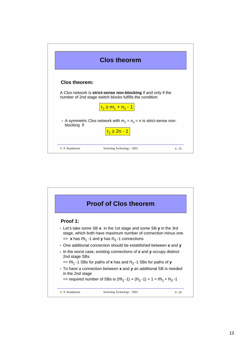
A Clos network is strict-sense non-blocking if and only if thenumber of 2nd stage switch blocks fulfills the condition
r2 ≥ m1 + n3 - 1
r2 ≥ 2n - 1
Clos theorem:
• A symmetric Clos network with m1 = n3 = n is strict-sense non-blocking if
4 - 26© P. Raatikainen Switching Technology / 2003
Proof of Clos theorem
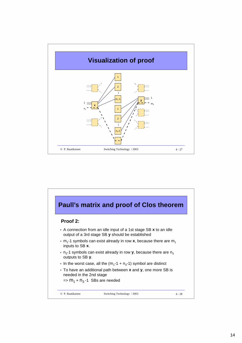
• Let’s take some SB x in the 1st stage and some SB y in the 3rdstage, which both have maximum number of connection minus one.=> x has m1 -1 and y has n3 -1 connections
• One additional connection should be established between x and y
• In the worst case, existing connections of x and y occupy distinct2nd stage SBs=> m1 -1 SBs for paths of x has and n3 -1 SBs for paths of y
• To have a connection between x and y an additional SB is neededin the 2nd stage=> required number of SBs is (m1 -1) + (n3 -1) + 1 = m1 + n3 -1
Proof 1:
14
4 - 27© P. Raatikainen Switching Technology / 2003
Visualization of proof
y
x
m1-1
2
1
...
n3-1
2
1
...
1
n1
1
m3
4 - 28© P. Raatikainen Switching Technology / 2003
Paull’s matrix and proof of Clos theorem
• A connection from an idle input of a 1st stage SB x to an idleoutput of a 3rd stage SB y should be established
• m1-1 symbols can exist already in row x, because there are m1
inputs to SB x.
• n3-1 symbols can exist already in row y, because there are n3
outputs to SB y.
• In the worst case, all the (m1-1 + n3-1) symbol are distinct
• To have an additional path between x and y, one more SB isneeded in the 2nd stage=> m1 + n3 -1 SBs are needed
Proof 2:
15
4 - 29© P. Raatikainen Switching Technology / 2003
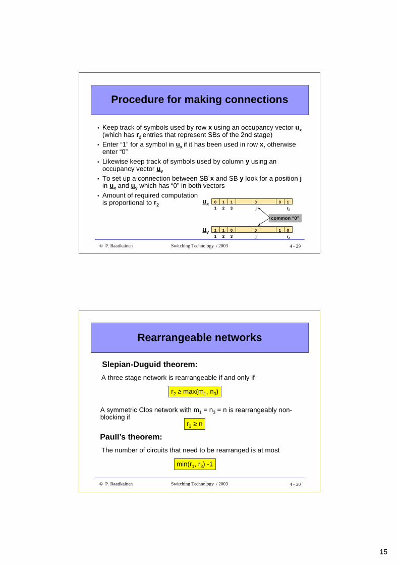
Procedure for making connections
• Keep track of symbols used by row x using an occupancy vector ux(which has r2 entries that represent SBs of the 2nd stage)
• Enter “1” for a symbol in ux if it has been used in row x, otherwiseenter “0”
• Likewise keep track of symbols used by column y using anoccupancy vector uy
• To set up a connection between SB x and SB y look for a position jin ux and uy which has “0” in both vectors
• Amount of required computationis proportional to r2
ux 0 1 1 0 0 1
1 2 3 j r2
1 1 0 0 1 0
1 2 3 j r2
uy
common “ 0”
4 - 30© P. Raatikainen Switching Technology / 2003
Rearrangeable networks
A three stage network is rearrangeable if and only if
r2 ≥ max(m1, n3)
Slepian-Dugu id theorem:
A symmetric Clos network with m1 = n3 = n is rearrangeably non-blocking if
r2 ≥ n
Paull ’s theorem:
The number of circuits that need to be rearranged is at most
min(r1, r3) -1
16
4 - 31© P. Raatikainen Switching Technology / 2003
Connection rearrangement byPaull’s matrix
• If there is no common symbol (position j) found in ux and uy, we lookfor symbols in ux that are not in uy and symbols in uy not found in ux
=> a new connection can be set up only by rearrangement
• Let’s suppose there is symbol a in ux (not in uy) and symbol b in uy(not in ux) and let’s choose either one as a starting point
• Let it be a then b is searched from the column in which a resides (inrow x) - let it be column j1 in which b is found in row i1
• In row i1 search for a - let this position be column j2 n
• This procedure continues until symbol a or b cannot be found in thecolumn or row visited
1 1 0 1 1
1 2 b r2
uy 1
a
ux 1 1 0 1 1
1 2 a r2
1
b
4 - 32© P. Raatikainen Switching Technology / 2003
Connection rearrangement by Paull’smatrix (cont.)
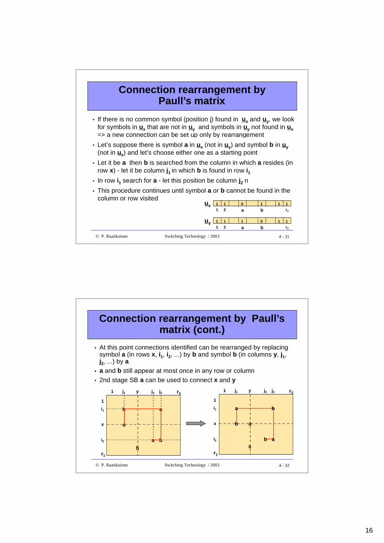
• At this point connections identified can be rearranged by replacingsymbol a (in rows x, i1, i2, ...) by b and symbol b (in columns y, j1,j2, ...) by a
• a and b still appear at most once in any row or column• 2nd stage SB a can be used to connect x and y
r3
b
1 j1
1
a
r1
y j3 j2
i1
x
i2 a
b
b a
r31 j1
1
r1
y j3 j2
i1
x
i2b
a
b
b
a b
a
17
4 - 33© P. Raatikainen Switching Technology / 2003
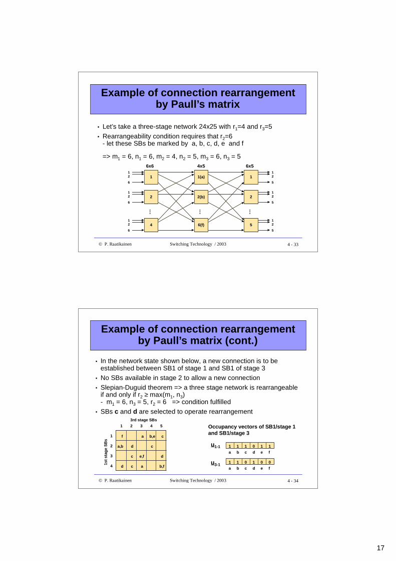
Example of connection rearrangementby Paull’s matrix
• Let’s take a three-stage network 24x25 with r1=4 and r3=5• Rearrangeability condition requires that r2=6
- let these SBs be marked by a, b, c, d, e and f
=> m1 = 6, n1 = 6, m2 = 4, n2 = 5, m3 = 6, n3 = 5
1
2
4
1(a)
2(b)
6(f)
6x6 4x5
1
2
5
6x512
6
12
6
12
6
12
5
12
5
12
5
…
…
…
4 - 34© P. Raatikainen Switching Technology / 2003
Example of connection rearrangementby Paull’s matrix (cont.)
1st
stag
e S
Bs
1 2
1
2
3
4
3 4 5
3rd stage SBs
f a b,e c
a,b
e,f
b,fd c
d
d
a
c
c
• In the network state shown below, a new connection is to beestablished between SB1 of stage 1 and SB1 of stage 3
• No SBs available in stage 2 to allow a new connection• Slepian-Duguid theorem => a three stage network is rearrangeable
if and only if r2 ≥ max(m1, n3)- m1 = 6, n3 = 5, r2 = 6 => condition fulfilled
• SBs c and d are selected to operate rearrangement
u1-1
u3-1
1 1 1 10
a b c
1
d e f
1 1 0 01
a b c
0
d e f
Occupancy vec tors of SB1/stage 1and SB1/stage 3
18
4 - 35© P. Raatikainen Switching Technology / 2003
Example of connection rearrangementby Paull’s matrix (cont.)
1st
stag
e S
Bs
1 2
1
2
3
4
3 4 53rd stage SBs
c,f a b,e d
a,b
e,f
b,fd c
c
c
a
d
d
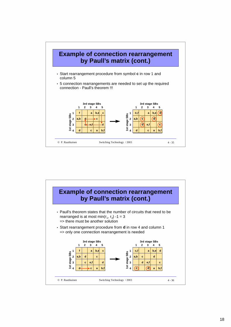
• Start rearrangement procedure from symbol c in row 1 andcolumn 5
• 5 connection rearrangements are needed to set up the requiredconnection - Paull’s theorem !!!
1st
stag
e S
Bs
1 2
1
2
3
4
3 4 53rd stage SBs
f a b,e c
a,b
e,f
b,fd c
d
d
a
c
c
4 - 36© P. Raatikainen Switching Technology / 2003
Example of connection rearrangementby Paull’s matrix (cont.)
1st
stag
e S
Bs
1 2
1
2
3
4
3 4 53rd stage SBs
f a b,e c
a,b
e,f
b,fd c
d
d
a
c
c
1st
stag
e S
Bs
1 2
1
2
3
4
3 4 53rd stage SBs
c,f a b,e d
a,b
e,f
b,fc d
c
c
a
d
d
• Paull’s theorem states that the number of circuits that need to berearranged is at most min(r1, r3) -1 = 3=> there must be another solution
• Start rearrangement procedure from d in row 4 and column 1=> only one connection rearrangement is needed
19
4 - 37© P. Raatikainen Switching Technology / 2003
Recursive construction of switchingnetworks
• To reduce cross-point complexity of three stage switches individualstages can be factored further
• Suppose we want to construct an NxN switching network and letN = pxq
• A rearrangeably non-blocking Clos network is constructedrecursively by connecting a pxp, qxq and pxp rearrangeably non-blocking switch together in respective order=> under certain conditions result may be a strict-sense non-blocking network
• A strict-sense non-blocking network is constructed recursively byconnecting a p(2p - 1), qxq and p(2p - 1) strict-sense non-blockingswitch together in respective order=> result may be a rearrangeable non-blocking network
4 - 38© P. Raatikainen Switching Technology / 2003
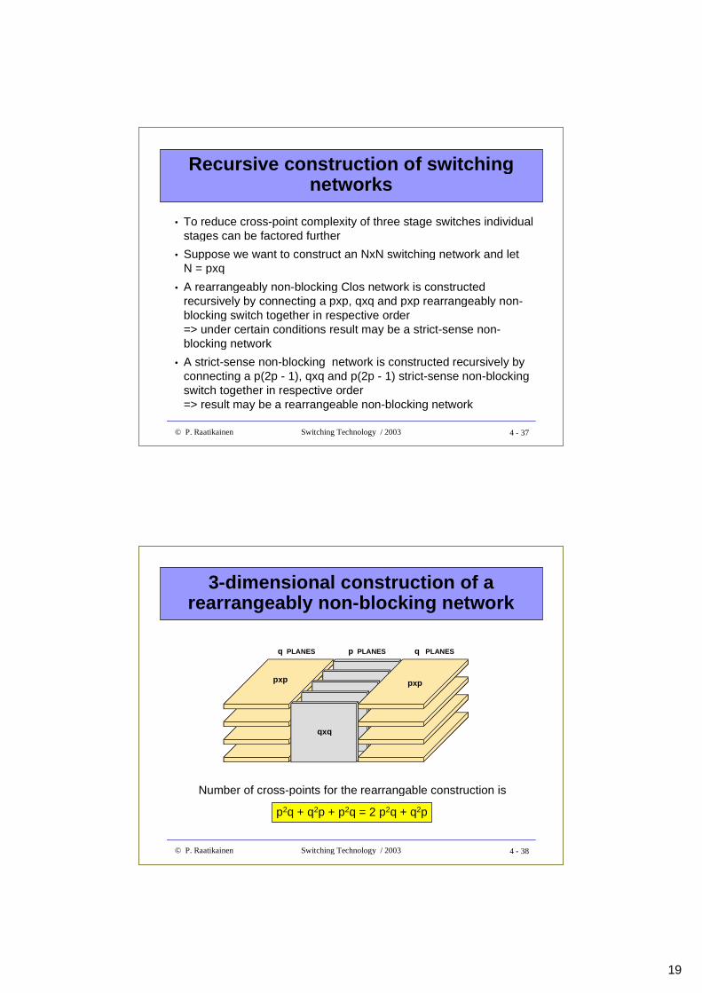
3-dimensional construction of arearrangeably non-blocking network
q PLANES p PLANES q PLANES
qxq
pxp pxp
Number of cross-points for the rearrangable construction is
p2q + q2p + p2q = 2 p2q + q2p
20
4 - 39© P. Raatikainen Switching Technology / 2003
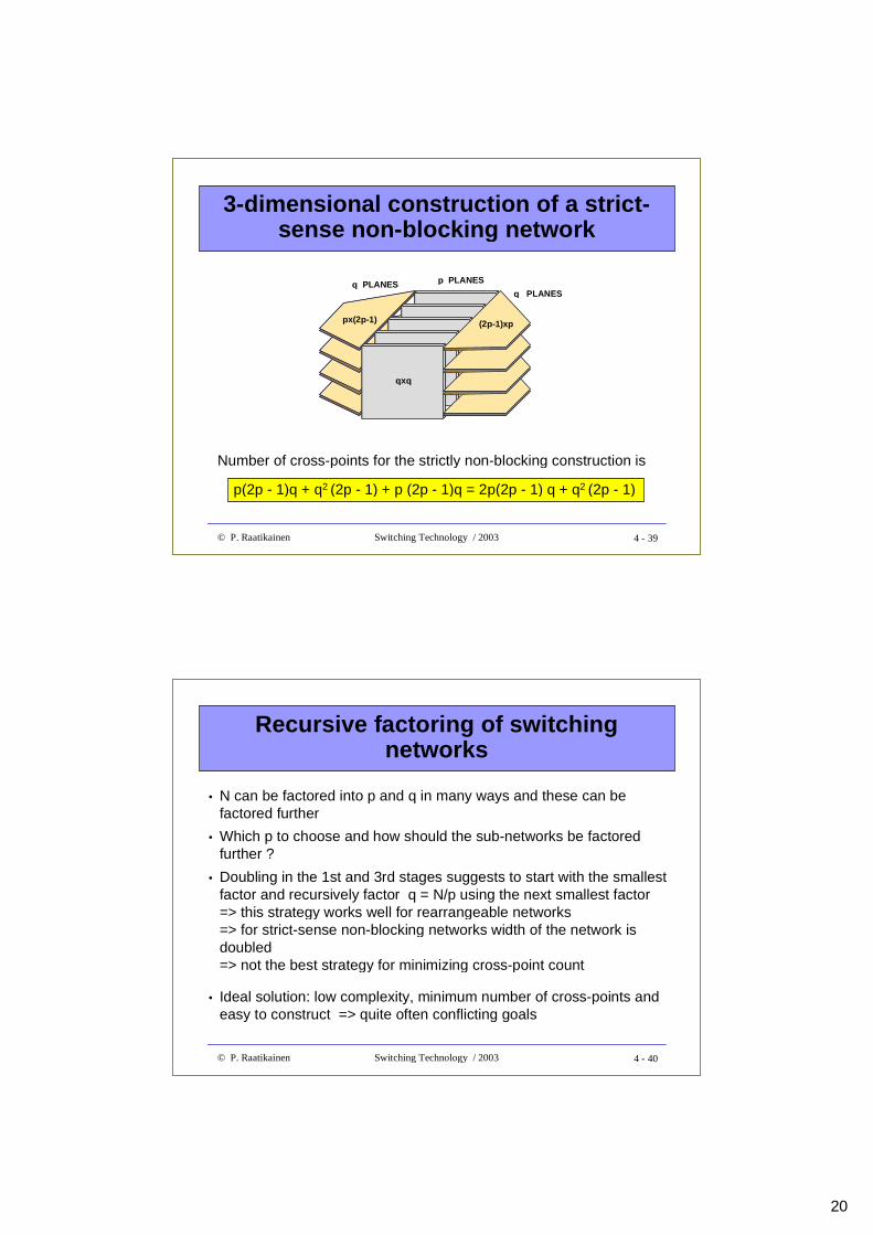
3-dimensional construction of a strict-sense non-blocking network
px(2p-1)
q PLANES p PLANES
q PLANES
qxq
(2p-1)xp
Number of cross-points for the strictly non-blocking construction is
p(2p - 1)q + q2 (2p - 1) + p (2p - 1)q = 2p(2p - 1) q + q2 (2p - 1)
4 - 40© P. Raatikainen Switching Technology / 2003
Recursive factoring of switchingnetworks
• N can be factored into p and q in many ways and these can befactored further
• Which p to choose and how should the sub-networks be factoredfurther ?
• Doubling in the 1st and 3rd stages suggests to start with the smallestfactor and recursively factor q = N/p using the next smallest factor=> this strategy works well for rearrangeable networks=> for strict-sense non-blocking networks width of the network isdoubled=> not the best strategy for minimizing cross-point count
• Ideal solution: low complexity, minimum number of cross-points andeasy to construct => quite often conflicting goals
21
4 - 41© P. Raatikainen Switching Technology / 2003
Recursive factoring of a rearrangeablynon-blocking network
N IN
PU
TS
N O
UT
PU
TS
N/2 x N/2SWITCH
N/2 x N/2SWITCH
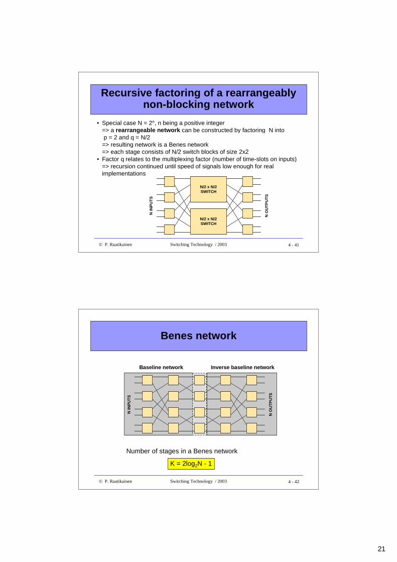
• Special case N = 2n, n being a positive integer=> a rearrangeable network can be constructed by factoring N into p = 2 and q = N/2=> resulting network is a Benes network=> each stage consists of N/2 switch blocks of size 2x2
• Factor q relates to the multiplexing factor (number of time-slots on inputs)=> recursion continued until speed of signals low enough for realimplementations
4 - 42© P. Raatikainen Switching Technology / 2003
Benes network
N IN
PU
TS
N O
UT
PU
TS
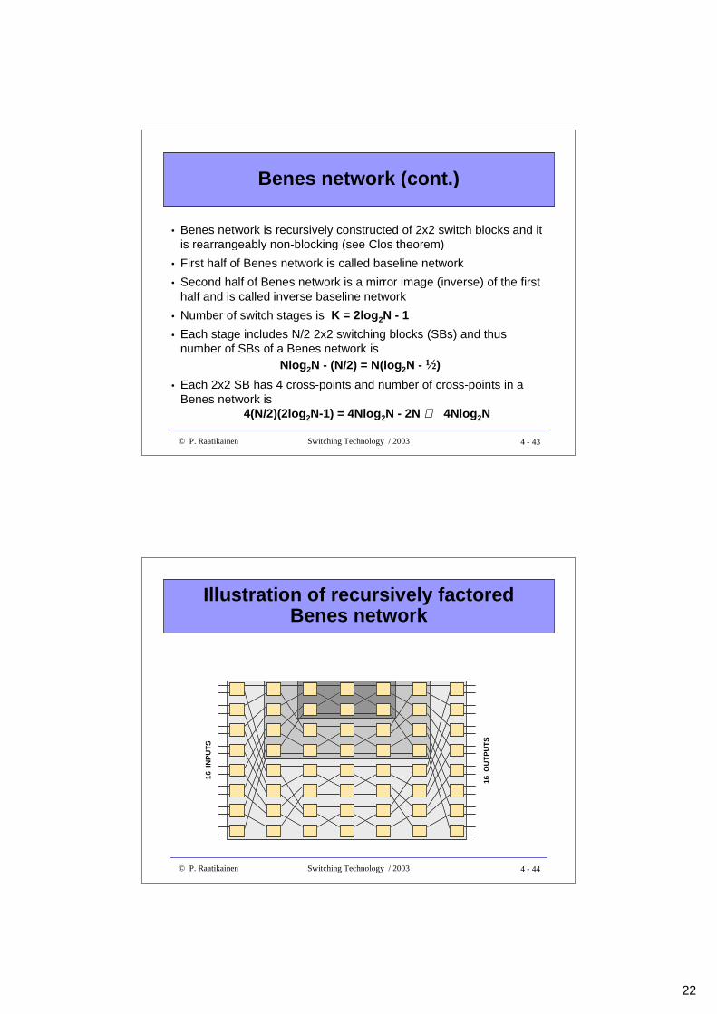
Number of stages in a Benes network
K = 2log2N - 1
Baseline network Inverse baseline network
22
4 - 43© P. Raatikainen Switching Technology / 2003
Benes network (cont.)
• Benes network is recursively constructed of 2x2 switch blocks and itis rearrangeably non-blocking (see Clos theorem)
• First half of Benes network is called baseline network
• Second half of Benes network is a mirror image (inverse) of the firsthalf and is called inverse baseline network
• Number of switch stages is K = 2log2N - 1
• Each stage includes N/2 2x2 switching blocks (SBs) and thusnumber of SBs of a Benes network is
Nlog2N - (N/2) = N(log2N - ½)
• Each 2x2 SB has 4 cross-points and number of cross-points in aBenes network is
4(N/2)(2log2N-1) = 4Nlog2N - 2N ∼∼ 4Nlog2N
4 - 44© P. Raatikainen Switching Technology / 2003
Illustration of recursively factoredBenes network
16 I
NP
UT
S
16 O
UT
PU
TS